SIMPL Windows基础教程
- 格式:pdf
- 大小:838.54 KB
- 文档页数:53


Simple企业管理系统快速上手指南广州斯盟派网络科技有限公司版权信息本文件的版权属于广州斯盟派网络科技有限公司任何形式的散发都必须事先得到广州斯盟派网络科技有限公司的书面许可目录第一章系统介绍 (4)1.1SIMPLE 企业管理系统概述 (4)1.2采购管理介绍 (4)1.3库存管理介绍 (5)1.4销售管理介绍 (5)1.5生产管理介绍 (5)1.6应收管理介绍 (6)1.7应付管理介绍 (6)第二章建立资料 (7)2.1货物分类 (7)2.2货物资料 (8)2.3仓库资料 (8)2.4采购员资料 (9)2.5供应商资料 (9)2.6业务员资料 (9)2.7客户资料 (9)2.8其它基础资料 (9)第三章数据初始化 (10)3.1库存数量初始化 (10)3.2应收款初始化 (10)3.3预收款初始化 (11)3.4应付款初始化 (11)3.5预付款初始化 (11)3.6现金银行初始化 (11)3.7科目余额初始化 (11)第四章采购流程 (13)4.1采购订单 (13)4.2采购订单查询 (14)4.3采购收货单 (16)4.4采购收货单查询 (17)4.5库存汇总表 (19)4.6付款单 (20)4.7应付款报表 (21)第五章销售管理 (24)5.1销售订单 (24)5.2销售发货单 (25)5.3销售退货单 (27)5.4收款单 (28)5.5.应收款报表 (29)第六章应收应付管理 (30)6.1先收货后付款业务 (30)6.2先预付款后收货业务 (30)6.3先发货后收款业务 (33)6.4先收款后发货业务 (34)第七章权限管理 (37)7.1操作员资料 (37)7.2新的操作员进入系统 (39)第八章月末结账 (41)8.1月末库存盘点 (41)8.2月末结账 (43)第一章系统介绍1.1simple 企业管理系统概述Simple企业管理系统是通过在多个行业众多客户的成功应用,形成的一套成熟稳定的ERP 产品。
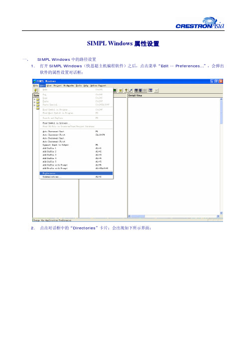
SIMPL Windows属性设置一、 SIMPL Windows中的路径设置1.打开SIMPL Windows(快思聪主机编程软件)之后,点击菜单“Edit -- Preferences…”,会弹出软件的属性设置对话框;2.点击对话框中的“Directories”卡片;会出现如下所示界面;3.上图中的路径含义是:z Default Program:快思聪SIMPL Windows软件的安装路径,不要更改;z Location for User Modules:用户采用标准SIMPL函数所编写的宏的路径;该目录下的宏将会在编程界面下“Symbol Library – User Modules”下显示出来;z Location for User SIMPL+:用户采用SIMPL+所编写的宏的路径;该目录下的宏将会在编程界面下“Symbol Library – User Modules”下显示出来;z Location for User:用户红外文件的路径;该目录下的红外文件将会在配置界面下“Device Library –- Crestron Device –- User Device –- User DB”下显示出来;4.创建标准的SIMPL函数宏,采用的命令是“File –- New Project/User Module”;而标准函数就是处于编程界面下“Symbol Library – Logic Symbols”下面的函数;5.创建SIMPL+的宏,采用的命令是“File –- New SIMPL+”;SIMPL+编程工具是一种基于指令行类型、与C语言类似的一种编程工具;6.采用标准SIMPL函数和采用SIMPL+编写的宏都会在编程界面下“Symbol Library – UserModules”下显示出来,但是他们的图标不一样:二、 SIMPL Windows中“Alt + 1”到“Alt + 5”快捷键的设置1.打开SIMPL Windows(快思聪主机编程软件)之后,点击菜单“Edit -- Preferences…”,会弹出软件的属性设置对话框;2.点击对话框中的“Program Editing”卡片;会出现如下所示界面;3.在上述对话框中设置号相应的快捷键内容之后,在编程时可以通过菜单或者相应的快捷键,给所选择的变量添加相应的后缀;。


Simplify3D® Quick Start Guide SOFTWARE SETUPThe Configuration AssistantWhen you open Simplify3D for the first time, youwill be greeted by the Configuration Assistant.Select your printer from the drop down menu toautomatically configure all of your settings.If you don’t see your printer listed on theConfiguration Assistant, please select the option for“Other” at the bottom of the list. If you needassistance creating a new profile, feel free tocontact Simplify3D Support for assistance.You can access the Configuration Assistant at anytime to change your settings to a different printer.Go to Help > Configuration Assistant.The Interface LayoutAfter the printer configuration is complete, you will see the main Simplify3D software interface. The major elements of the software interface are identified below.FOUR STEPS TO YOUR FIRST PRINT1. PrepareThe first step of the 3D printing process in Simplify3D is to import the model you want to build.You may obtain 3D models from a variety of online repositories, such as or , or you can make your own model using CAD software. Save the 3D model fileas an .stl or .obj file.Click Import in the Models section and navigate to the folder where you saved your file. Youcan also drag-and-drop file(s) onto the Build Table. Click onCenter and Arrange to move your models to the center ofthe build plate. Use Tool Bar options (listed vertically on theright side of the window) to view and manipulate your model.2. ProcessNow you will define a Process that specifies how your model will beconstructed. Most models use a single process; more complicated modelsmay use multiple processes. The first Process will be configuredautomatically based on the printer selected in the Configuration Assistant.You can make any adjustments you choose, but “Process1” is a great placeto start!To make adjustments to your Process, double-click on the Process or clickEdit Process Settings. This will open the FFF Settings window.**The acronym FFF stands for Fused Filament Fabrication, and refers to 3D printing using filament-based materials.The FFF Settings window contains all the settings that specify how your model will beconstructed:• Select Profile: Loads aprinter profile and thecorresponding settings, whichhave been selected to ensureoptimum quality.• Auto-Configure forMaterial: Adjuststemperature, extrusion, andcooling settings based on thematerial you select.• Auto-Configure for Print Quality: Adjusts layer height, infill density, and other quality settings based on the level you desire.• Auto-Configure Extruders: This selection box appears if you selected aprinter with multiple extruders. Select the extruders that you intend to use and they will be automatically enabled.• Infill Percentage: Adjusts the interior solidity of your 3D print. 0% is completely hollow and 100% is completely solid. A value in the range of 20-50% is frequently used.• Include Raft: Generates a raft structure underneath your part. Rafts are used to improve the bond to your build platform and may help reduce warping on large models. A raft can also compensate for slight leveling issues if you have difficulty with first layer adhesion. • Generate Support: Turns on the Support Generation Tool. Support structuresare used when your model has steep overhangs or unsupported areas. Typically,overhangs greater than 45º benefit from support material underneath it. Simplify3D also allows you to customize the location of your support structures; simply click to add ordelete! Support structures break away cleanly and easily, minimizing damage and ensuring high quality models.Click OK when you have finished configuring your settings in the FFF Settingswindow. At any time, you can modify the settings by double-clicking on the Processin the list, or by clicking Edit Process Settings. Click Show Advanced to view additional options.3. PreviewAfter you have finalized your Process settings, click Prepare to Print! This will initiate two important functions: Simplify3D will “slice” your model and transition to the Preview Mode.“Slicing” is the term used to describe the process of converting adigital model into line-by-line printer instructions called G-Code. Thelightning-fast slicer in Simplify3D quickly prepares G-Code based onthe variables you selected in the FFF Settings window.The animated Preview Modeallows you to inspect all aspects ofyour print operation prior toexecution. The software reads theG-Code and displays line-by-line orlayer-by-layer how your model willbe constructed.The Preview provides interactivebuttons for precise inspection ofyour build sequence:• Play/PauseButton: Animates thePreview by line or by layer.• Start and End Slider Bars: Allow you to move through the Preview manually.(Hint: leave the Start slider positioned left and drag the End slider right to view the build sequence.)A useful setting is to select Preview by Layer and also place a checkmark in SingleLayer Only. Together, these selections will allow you to view one layer at a time.If you want to make further adjustments to your model or process before printing, click Exit Preview Mode. This is a great time to ensure that your model is constructed properly.The Preview Window also contains estimates about your print project. These Build Statistics appear in the top left corner of the Preview window.• Build Time: How long it would take for your print to finish.• Filament Length: How much filament it will take to build your model.• Weight: How much the print will weigh when completed.*• Material Cost: An approximation of how much it will cost to make your part.* *To adjust the density or cost per kg values, please select Edit Process Settings then browse to the Other tab.4. PrintWhen you are satisfied with the Preview, there are two methods for how to start your print: Begin Printing over USB: if you are using a USB connection, you have the option to view the build sequence real-time on your monitor by selecting Live Preview Tracking. For additional information on USB communication, access the Machine Control Panel by going to Tools > Machine Control Panel to view a broad range of information that is transmitted via USB.Save Toolpaths to Disk: This saves your print file to a user-defined location, such as a folder on your computer or an SD card. The software will save a .gcode file and then automatically create a .X3G, .MakerBot or other print-type file if needed.Additional ResourcesFor more information about any particular setting, useyour mouse to hover over the setting to display atooltip describing the functionality.These additional support materials are found at.• Print Troubleshooting Guide• YouTube Video Resources• Tutorials• Hardware Setup Guides• User Forum• FAQ Hover over text to see TooltipsThank you for purchasing Simplify3D Software, and happy printing!。
simpleshow使用方法
simpleshow是一个用于制作简单易懂的解释性视频的工具。
它可以帮助用户通过动画、图表和文字来解释复杂的概念。
以下是使用simpleshow的一般步骤:
1. 注册和登录,首先,你需要在simpleshow的官方网站上注册一个账户并登录。
2. 创建新视频,登录后,你可以选择创建一个新的视频项目。
3. 选择模板,simpleshow提供了各种不同类型的模板,你可以根据你的视频内容选择合适的模板。
4. 编辑文本,在模板中,你可以编辑视频中的文字内容,包括标题、段落和标语。
5. 添加图像和图表,你可以上传图片或者添加图表来支持你的解释性视频内容。
6. 选择语音,你可以选择使用电脑生成的语音,也可以自己录
制声音来配合视频内容。
7. 预览和调整,完成文本、图像和语音的添加后,你可以预览视频并进行必要的调整。
8. 导出和分享,最后,你可以将制作好的视频导出为常见的视频格式,并分享到社交媒体或者网站上。
除了以上基本步骤,simpleshow还提供了一些高级功能,比如自定义动画、添加背景音乐等。
希望这些信息能够帮助你更好地使用simpleshow制作解释性视频。
Simple Solver 是一个简单易用的求解器,可以用于解决各种数学问题和工程问题。
它支持多种数学函数和符号,可以用于符号计算和数值计算。
本文将介绍 Simple Solver 的使用方法,供初学者参考。
一、下载安装 Simple Solver1. 打开浏览器,输入 Simple Solver 的冠方全球信息站位置区域。
2. 在全球信息站首页找到并点击“下载”按钮。
3. 根据系统要求选择合适的版本下载,并按照提示安装。
二、启动 Simple Solver1. 安装完成后,在桌面双击 Simple Solver 图标,或者在开始菜单中找到 Simple Solver 并点击打开。
2. 确保计算机已连接至互联网,Simple Solver 会自动进行更新和授权验证。
三、创建新的求解项目1. 在 Simple Solver 主界面点击“新建”按钮,或者在菜单栏选择“文件”-“新建”。
2. 在弹出的对话框中选择项目类型,输入项目名称,点击“确定”。
四、输入数学表达式1. 在主界面的输入框中输入需要求解的数学表达式,支持基本运算符、括号、函数等。
2. 可以通过键盘输入或者点击屏幕上的按钮进行输入。
五、设置求解参数1. 在界面的右侧可以设置求解的参数,比如精度、迭代次数、求解方法等。
2. 根据具体问题的要求进行相应的参数设置。
六、进行求解1. 确认输入的表达式和参数都设置完成后,点击“求解”按钮进行计算。
2. 程序会在界面上显示计算过程和结果,也可以保存结果或者输出成文本、图片等格式。
七、保存和导出1. 在求解过程中可以随时保存当前项目,以便后续修改或查看。
2. 也可以将结果导出成文件,比如图片、PDF 等格式,方便进行打印或者共享。
八、关闭程序1. 在完成所有操作后,可以点击“退出”按钮,或者在菜单中选择“文件”-“退出”来关闭 Simple Solver。
以上就是Simple Solver 的基本使用方法,希望对初学者能有所帮助。
WindowsMobile操作系统开发入门教程
WindowsMobile操作系统开发入门教程
WindowsMobile操作系统开发如何进行呢?以下是店铺为大家搜索整理的WindowsMobile操作系统开发入门教程,希望对正在关注的您有所帮助!
Professional版
1.安装虚拟网卡驱动netsvwrap.msi或Virtual PC 2007
2.启动Visual Studio 2005,菜单选择:工具->选项->设备工具->设备.在右侧的模拟器列表中选中要配置的'模拟器,点击属性按钮,进入仿真器配置界面
3.按下图所示配置
4.点击仿真器按钮。
进入仿真器配置界面,点选Network标签。
作如下配置:
5.启动仿真器,成功连接仿真设备后,电话菜单:开始->设置->连接,切换到“连接”选项,如下图:
6.单击“网卡”,打开“配置网络适配器”窗体。
在“我的网卡连接到”中,选择“默认单位设置”或“默认Internet设置”,在“点击适配器以修改设置”中,选择“NE2000 兼容Ethernet驱动程序”。
如下图:
7.选择完适配器后,会自动打开适配器网络设置窗口。
根据实际网络来分配IP(IP不能有冲突)、网关、DNS等。
如下图:或只选择“使用服务器分配的IP地址”,如下图:
下载全文。