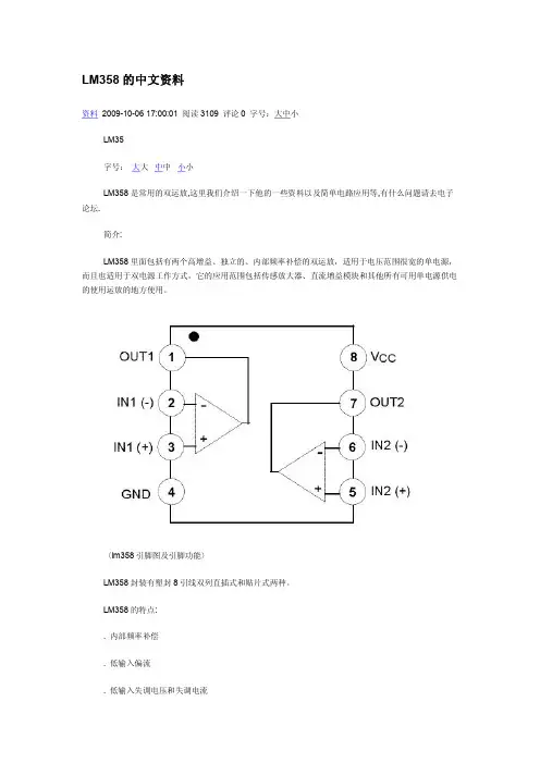
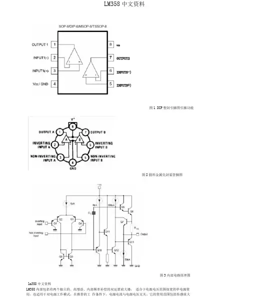
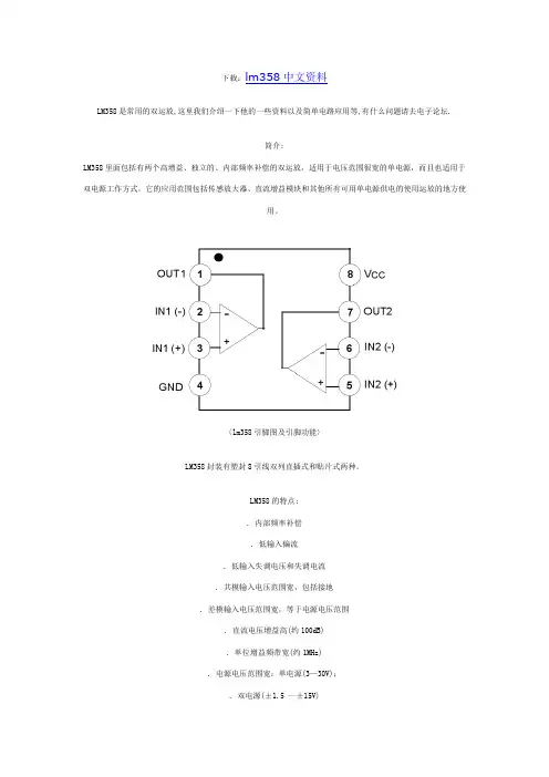
FDN358P_NL中文资料
- 格式:pdf
- 大小:113.52 KB
- 文档页数:5
V mV/°C
125 210 200
mΩ
VGS = –10 V, ID = –1.5 A,TJ=125°C VGS = –4.5 V, VDS = –5 V, –5
ID(on) gFS
On–State Drain Current Forward Transconductance
A 3.5 S
Dynamic Characteristics
td(on) tr td(off) tf Qg Qgs Qgd Turn–On Delay Time Turn–On Rise Time Turn–Off Delay Time Turn–Off Fall Time Total Gate Charge Gate–Source Charge Gate–Drain Charge
2 -3.0V 1
0 0 0.5 1 1.5 2 2.5 -VDS, DRAIN TO SOURCE VOLTAGE (V)
Figure 1. On-Region Characteristics.
Figure 2. On-Resistance Variation with Drain Current and Gate Voltage.
5 VDS = -5V -ID, DRAIN CURRENT (A) 4 125oC 3 25oC -IS, REVERSE DRAIN CURRENT (A) TA = -55oC
Figure 4. On-Resistance Variation with Gate-to-Source Voltage.
10 VGS = 0V 1 TA = 125oC 0.1 25oC 0.01 -55oC
2
1
0.001
0 1.5 2 2.5 3 3.5 4 -VGS, GATE TO SOURCE VOLTAGE (V)
0.0001 0.0 0.2 0.4 0.6 0.8 1.0 1.2 -VSD, BODY DIODE FORWARD VOLTAGE (V)
IS VSD Maximum Continuous Drain–Source Diode Forward Current Drain–Source Diode Forward VGS = 0 V, IS = –0.42 A Voltage –0.42
(Note 2)
A V
–0.76
–1.2
Notes: 1. RθJA is the sum of the junction-to-case and case-to-ambient thermal resistance where the case thermal reference is defined as the solder mounting surface of the drain pins. RθJC is guaranteed by design while RθCA is determined by the user's board design. a) 250°C/W when mounted on a 0.02 in2 pad of 2 oz. copper.
b) 270°C/W when mounted on a minimum pad.
Scale 1 : 1 on letter size paper 2. Pulse Test: Pulse Width ≤ 300 µs, Duty Cycle ≤ 2.0%
FDN358P Rev G (W)
元器件交易网
Device Marking 358 Device FDN358P Reel Size 7’’ Tape width 8mm Quantity 3000 units
2003 Fairchild Semiconductor Corporation
FDN358P Rev G (W)
元器件交易网
0.4 RDS(ON), ON-RESISTANCE (OHM)
1.6 RDS(ON), NORMALIZED DRAIN-SOURCE ON-RESISTANCE ID = -1.5A VGS = -10V 1.4
ID = -0.75A 0.3 TA = 125oC 0.2 TA = 25oC 0.1
Thermal Characteristics
RθJA RθJC Thermal Resistance, Junction-to-Ambient Thermal Resistance, Junction-to-Case
(Note 1a) (Note 1)
ห้องสมุดไป่ตู้250 75
°C/W °C/W
Package Marking and Ordering Information
Features
• –1.5 A, –30 V. RDS(ON) = 125 mΩ @ VGS = –10 V RDS(ON) = 200 mΩ @ VGS = –4.5 V • Low gate charge (4 nC typical) • High performance trench technology for extremely low RDS(ON) . • High power version of industry Standard SOT-23 package. Identical pin-out to SOT-23 with 30% higher power handling capability.
Figure 5. Transfer Characteristics.
Figure 6. Body Diode Forward Voltage Variation with Source Current and Temperature.
FDN358P Rev G (W)
元器件交易网
FDN358P
Electrical Characteristics
Symbol
BVDSS ∆BVDSS ∆TJ IDSS IGSSF IGSSR
T A = 25°C unless otherwise noted
Parameter
Drain–Source Breakdown Voltage Breakdown Voltage Temperature Coefficient Zero Gate Voltage Drain Current Gate–Body Leakage, Forward Gate–Body Leakage, Reverse
Parameter
Ratings
–30 ±20
(Note 1a)
Units
V V A
–1.5 –5 0.5 0.46 –55 to +150
Power Dissipation for Single Operation
(Note 1a) (Note 1b)
W °C
Operating and Storage Junction Temperature Range
FDN358P
Typical Characteristics
10 -VGS, GATE-SOURCE VOLTAGE (V)
250
ID = -1.5A VDS = -5V -10V
CISS 200 CAPACITANCE (pF)
f = 1 MHz VGS = 0 V
Min
–30
Typ
Max Units
V
Off Characteristics
–22 –1 –10 100 –100 nA nA mV/°C µA
On Characteristics
VGS(th) ∆VGS(th) ∆TJ RDS(on)
Gate Threshold Voltage Gate Threshold Voltage Temperature Coefficient Static Drain–Source On–Resistance
D
D
S
G S
SuperSOT -3
TM
G
TA=25oC unless otherwise noted
Absolute Maximum Ratings
Symbol
VDSS VGSS ID PD TJ, TSTG Drain-Source Voltage Gate-Source Voltage Drain Current – Continuous – Pulsed
Ciss Coss Crss Input Capacitance Output Capacitance Reverse Transfer Capacitance
(Note 2)
VDS = –15 V, f = 1.0 MHz
V GS = 0 V,
182 56 26
pF pF pF
Switching Characteristics
VDD = –15 V, VGS = –10 V,
ID = –0.5 A, RGEN = 6 Ω
5 13 12 2
10 23 21 4 5.6
ns ns ns ns nC nC nC
VDS = –15V, VGS = –10 V
ID = –1.5 A,
4 0.8 0.8
Drain–Source Diode Characteristics and Maximum Ratings
元器件交易网
FDN358P
January 2003
FDN358P
Single P-Channel, Logic Level, PowerTrench MOSFET
General Description
This P-Channel Logic Level MOSFET is produced using Fairchild Semiconductor advanced Power Trench process that has been especially tailored to minimize the on-state resistance and yet maintain low gate charge for superior switching performance. These devices are well suited for portable electronics applications: load switching and power management, battery charging circuits, and DC/DC conversion.