Piston items
- 格式:doc
- 大小:36.50 KB
- 文档页数:2

Tractors: 20 Cockshutt & E2 Co-op After # 962; 20K, 22, 23 (Mustang), 82, 101 Jr, 102 Jr Massey Harris;QTY ITEM #DESCRIPTIONLETTERED ITEMS INCLUDED IN KIT1985244Out-of-Frame Kit O4 4 4181236181311181312STD Piston Assembly (3-1/8 1-1/4 Grooves).020 Piston Assembly (3-1/8 1-1/4 Grooves).030 Piston Assembly (3-1/8 1-1/4 Grooves)O4181313.040 Piston Assembly (3-1/8 1-1/4 Grooves)4181314.060 Piston Assembly (3-1/8 1-1/4 Grooves) 3-1/8 1-1/4 4181315.080 Piston Assembly (3-1/8 1-1/4 Grooves)4 4181316181317STD Ring Set (3-1/8 1-1/4).020 Ring Set (3-1/8 1-1/4)O4181318.030 Ring Set (3-1/8 1-1/4)4181319.040 Ring Set (3-1/8 1-1/4)4181321.060 Ring Set (3-1/8 1-1/4) 3-1/8 1-1/4 4181322.080 Ring Set (3-1/8 1-1/4)4 4181323181324STD Ring Set (3-1/8 1-3/16).020 Ring Set (3-1/8 1-3/16)4181325.030 Ring Set (3-1/8 1-3/16)4181326.040 Ring Set (3-1/8 1-3/16) 3-1/8 1-3/16 4181327.060 Ring Set (3-1/8 1-3/16)4 4181328181329STD Ring Set (3-3/32 1-1/4).020 Ring Set (3-3/32 1-1/4)4181331.030 Ring Set (3-3/32 1-1/4)4181332.040 Ring Set (3-3/32 1-1/4)3-3/32 1-1/4 4181333.060 Ring Set (3-3/32 1-1/4)4101157Notched Repair Liner (3.378" OD / 7.500" OAL)4101158Notched Repair Liner (3.4405" OD / 7.500" OAL)4101146Universal Repair Liner (3.378" OD / 9.250" OAL)4101147Universal Repair Liner (3.4405" OD / 9.250" OAL)APPLICATION: Combines: 35 & Super 35 Massey Ferguson; Forklifts & Power Units;Tractors: 20 Cockshutt & E2 Co-op After # 962; 20K, 22, 23 (Mustang), 82, 101 Jr, 102 Jr Massey Harris;1 281372 STD Rod Bearing Set (2-LH & 2-RH) O1 281373 .010 Rod Bearing Set (2-LH & 2-RH)1 281374 .020 Rod Bearing Set (2-LH & 2-RH)1 281375 .030 Rod Bearing Set (2-LH & 2-RH)1 281376 .040 Rod Bearing Set (2-LH & 2-RH)1 281377 .060 Rod Bearing Set (2-LH & 2-RH)1 281396 STD Main Bearing Set wo/Thrust Washer1 281397 .010 Main Bearing Set wo/Thrust Washer1 281398 .020 Main Bearing Set wo/Thrust WasherSingle Flange Front 1 281399 .030 Main Bearing Set wo/Thrust WasherWasher Optional 1 281316 Thrust Washer1 281411 STD Main Bearing Set wo/Thrust Washer1 281412 .010 Main Bearing Set wo/Thrust Washer1 281413 .020 Main Bearing Set wo/Thrust Washer1 281414 .030 Main Bearing Set wo/Thrust WasherFlangeless Front 1 281415 Thrust WasherWashers Optional 1 281416 Thrust Washer1 281421 Thrust Washer O1 281422 Thrust Washer1 281423 Thrust Washer1 281424 Thrust Washer Flangeless Front 1 281425 Thrust WasherWashers Included1 381319 Head Gasket Set1 381323 Head Gasket8 301138 Positive Valve Seals "Recommended"1 381318 Full Gasket Set w/Seals O1 381333 Tappet Cover Gasket1 321318 Manifold Gasket1 381335 Timing Cover Set: Except Towmotor1 381336 Timing Cover Set: Towmotor1 381322 Pan Gasket Set1 381261 Front Crank Seal1 301123 Front Wear Sleeve1 381321 Rear Crank Seal Set4 281283 Pin Bushing (Split Bushing / .915" OD)4 281286 Pin Bushing (Full Round Solid Bushing / .915" OD)4 281284 .0055 Oversize Pin Bushing (Full Round Solid / .9205" OD)4 281431 Pin Bushing, Early Rods (1.063" OD)4 281432 .010 Oversize Pin Bushing, Early Rods (1.073" OD)1 281433 Cam Bushing Set8 781195 Rod Bolt8 781196 Rod NutLETTERED ITEMS INCLUDED IN KIT DESCRIPTION QTY ITEM #Tractors: 20 Cockshutt & E2 Co-op After # 962; 20K, 22, 23 (Mustang), 82, 101 Jr, 102 Jr Massey Harris;QTY ITEM #DESCRIPTIONLETTERED ITEMSINCLUDED IN KIT1 581247 Camshaft: Tractors (Cast / Solid Nose / 3 Bolt Thrust Plate)1 581248 Camshaft (Cast / Solid Nose /2 Bolt Thrust Plate)1 581249 Camshaft (Cast / Hollow Nose /2 Bolt Thrust Plate)1 581251 Camshaft (Steel / Solid Nose /2 Bolt Thrust Plate)1 581252 Camshaft (Steel / Hollow Nose / 2 Bolt Thrust Plate)1 581253 Cam Thrust Plate (2 Bolt)1 581254 Cam Thrust Plate (3 Bolt)1 591125 Cam Key (5/32" x 5/8")1 581255 Cam Nut (3/4" NF Special)1 581256 Cam Nut (7/8")1 581257 Cam Nut (1")8 581258 STD Tappet8 581259 .001 Oversize Tappet8 581261 .002 Oversize Tappet8 581262 .003 Oversize Tappet8 581263 .005 Oversize Tappet4 481261 Exhaust Valve (Drilled Stem / 1.203" Head)4 481263 Exhaust Valve (Drilled Stem / 1.328" Head)4 481264 Exhaust Valve (Stepped 5/16" Tip / Grooved / 1.203" Head)4 481265 Exhaust Valve (Grooved Stem / 1.203" Head / Stellite)4 481267 Exhaust Valve (Taper Groove / 1.203" Head / Free Rotating)4 481268 Exhaust Valve (Taper Groove / 1.328" Head / Free Rotating)4 481262 Intake Valve (Drilled Stem / 1.520" Head)4 481266 Intake Valve (Stepped 5/16" Tip / Grooved / 1.516" Head)8 481275 Intake & Exhaust Valve Guide (.343" ID) (1)4 481276 Exhaust Valve Guide, w/Free Rotating Valves (.375" ID)8 481168 Valve Spring4 481169 Exhaust Valve Rotator8 481172 Valve Keeper, Use w/Drilled Stem (Pin Type Lock)16 481171 4812668 481278 Valve Keeper, Use w/Free-Rotating Ex Valves8 481279 Valve Retainer, w/Pin Type Lock4 481281 Intake Retainer, w/Taper Lock Keeper4 481282 Stem Cap, Free-Rotating Exhaust Valve4 401146 STD Exhaust Seat, w/1.203" Valve (1.087"x1.348"x .200")4 481212 .010 Exhaust Seat, w/1.203" Valve (1.087"x1.358"x .200")4 401132 STD Exhaust Seat, w/1.328" Valve (1.187 x 1.442" x .219")4 401161 .010 Exhaust Seat, w/1.328" Valve (1.187 x 1.452" x .219")4 401128 STD Intake Seat (1.375 x 1.630" x .219")4 401162 .010 Intake Seat (1.375 x 1.640" x .219")APPLICATION: Combines: 35 & Super 35 Massey Ferguson; Forklifts & Power Units;Tractors: 20 Cockshutt & E2 Co-op After # 962; 20K, 22, 23 (Mustang), 82, 101 Jr, 102 Jr Massey Harris;1 1 1 581264 581265 581267 Cam Gear, F400H310 (48 Tooth / 1.000" Hub Length) Cam Gear, F400H405 (Hardened / 48 Tooth / 1.000" Hub)Cam Gear, F400H227 (Hardened / 48 Tooth / 1.187" Hub)1 581268 Cam Gear, F124H302 (48 Tooth / .906" Hub w/Gov)1 581269 Cam Gear, F124H401 (Hardened / 48 T / .906" Hub w/Gov)1 581271 Crank Gear, D600H300 (24 Tooth)1 581272 Crank Gear, F400H326 (Hardened / 24 Tooth)1 581273 Idler Gear, F400H3240 (39 Tooth / Bushing Type)1 581274 Idler Gear, F209H3011 (43 Tooth)1 581275 Fan Drive Gear, F209H303 (20 Tooth)1 581277 Pump Gear, F400H321 (36 Tooth)1 581278 Pump Gear, F400H330 (29 Tooth)1 581279 Pump Gear, F400H337 (24 Tooth)1 581281 Pump Gear, F600H318 (34 Tooth)48 T Cam Gear 1 581282 Accessory Drive Gear, F162H200 (24 Tooth)1 1 1 581283 581284 581287Cam Gear, F400H403 (Hardened / 56 Tooth) Crank Gear, F226H202 (Hardened / 28 Tooth)1 581288 Crank Gear, F600H317 (Hardened / 28 Tooth)1 581289 Crank Gear, F400H334 (28 Tooth)56 T Cam Gear 1 581292 Idler Gear, F600H321 (50 Tooth / Bearing Type)1 681141 Oil Pump (Cast Gear / 7 1/8" Flg to Tip / Bypass&Full Flow)1 681142 Oil Pump (Steel Gear / 7 1/8" Flg to Tip / Bypass&Full Flow) 1 681147 Oil Pump (Cast Drive Gear / 9 1/8" Mtg Flange to Shaft Tip)1 681148 Oil Pump (Steel Drive Gear / 9 1/8" Mtg Flange to Shaft Tip)1 681155 Oil Pump Kit, OEM Pumps w/Cast Drive Gear1 681156 Oil Pump Kit, OEM Pumps w/Steel Drive Gear1 681157 Cast Drive Gear "Use w/Cast Camshafts"1 681158 Steel Drive Gear "Use w/Steel Camshafts"1 681149 Oil Pump Screen1 681159 Oil Pump Drive Shaft Support Bushing "Fits in Block"1 281294 Thrust Adjustment Shim Package (.002 & .008 Shims)1 781197 Crankshaft Thrust Plate: Engines w/Front Thrust Bearing1 781198 Expansion Plug Kit (Includes 3-Block & 1-Cam Plug)1 881156 Thermostat (180 Degree)LETTERED ITEMSINCLUDED IN KITDESCRIPTION QTY ITEM #。
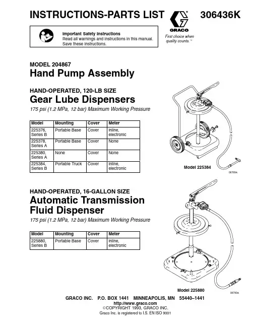
306436KFirst choice when quality counts.tINSTRUCTIONS-PARTS LISTImportant Safety InstructionsRead all warnings and instructions in this manual.Save these instructions.MODEL 204867Hand Pump AssemblyHAND-OPERATED, 120-LB SIZEGear Lube Dispensers175 psi (1.2 MPa, 12 bar) Maximum Working PressureModel Mounting Cover Meter 225376,Series B Portable Base Cover inline,electronic 225378,Series A Portable Base Cover None 225380,Series A NoneCover None 225384,Series BPortable TruckCoverinline,electronicHAND-OPERATED, 16-GALLON SIZEAutomatic Transmission Fluid Dispenser175 psi (1.2 MPa, 12 bar) Maximum Working PressureModel Mounting CoverMeter 225880,Series BPortable BaseCoverinline,electronicGRACO INC.P .O. BOX 1441MINNEAPOLIS, MN 55440–1441E COPYRIGHT 1993, GRACO INC.Graco Inc. is registered to I.S. EN ISO 900106789A06790ATable of Contents. . . . . . . . . . . . . . . . . . . . . . . . . . . . . . . . . . . . . . . . . . . . . . . . . . . . . . . . . . . . . . . . . . . . . . . . . . . . . . . . . . . . . . . . . . Installation3 . . . . . . . . . . . . . . . . . . . . . . . . . . . . . . . . . . . . . . . . . . . . . . . . . . . . . . . . . . . . . . . . . . . . . . . . . . . . . . . . . . . . . . . . . . Operation4 Dimensions Chart 4 . . . . . . . . . . . . . . . . . . . . . . . . . . . . . . . . . . . . . . . . . . . . . . . . . . . . . . . . . . . . . . . . . . . . . . . . . . . . . . . . . . .. . . . . . . . . . . . . . . . . . . . . . . . . . . . . . . . . . . . . . . . . . . . . . . . . . . . . . . . . . . . . . . . . . . . . . . . . . . . . . . . . . . . . . . . . . . . Service6 Parts. . . . . . . . . . . . . . . . . . . . . . . . . . . . . . . . . . . . . . . . . . . . . . . . . . . . . . . . . . . . . . . . Hand Pump Assembly, Model 2048677. . . . . . . . . . . . . . . . . . . . . . . . . . . . . . . . . . . . . . . . . . . . . . . Gear Lube Dispensers, Models 225378, 225376, 2253808. . . . . . . . . . . . . . . . . . . . . . . . . . . . . . . . . . . . . . . . . . . . . . . . . . . . . . . . . . . . . . . . Gear Lube Dispenser, Model 2253849. . . . . . . . . . . . . . . . . . . . . . . . . . . . . . . . . . . . . . . . . . . . . . . Automatic Transmission Fluid Dispenser, Model 22588010. . . . . . . . . . . . . . . . . . . . . . . . . . . . . . . . . . . . . . . . . . . . . . . . . . . . . . . . . . . . . . . . . . . . Truck Assembly, Model 20365010. . . . . . . . . . . . . . . . . . . . . . . . . . . . . . . . . . . . . . . . . . . . . . . . . . . . . . . . . . . . . Portable Base Assembly, Model 20362211. . . . . . . . . . . . . . . . . . . . . . . . . . . . . . . . . . . . . . . . . . . . . . . . . Hose and Meter Assemblies, Models 239707, 23970511 Warranty 12 . . . . . . . . . . . . . . . . . . . . . . . . . . . . . . . . . . . . . . . . . . . . . . . . . . . . . . . . . . . . . . . . . . . . . . . . . . . . . . . . . . . . . . . . .. . . . . . . . . . . . . . . . . . . . . . . . . . . . . . . . . . . . . . . . . . . . . . . . . . . . . . . . . . . . . . . . . . . . . . . . . . . . . . . Graco Phone Number122306436Installation See Fig.1 or Fig. 2, depending on your model.Models with a Portable TruckInsert the truck handle (708) into the sockets in thetruck base (701).All ModelsPlace a full container of fluid on the base. Carefullyclean the container top before opening it to avoid fluid contamination. Secure the drum or shield (401) withthe hardware provided.Models with a Drum CoverInstall the drum cover (601) on the opened drum andsecure it with the thumbscrews (603).All ModelsSlide the pump extension tube (318) all the way downon the riser tube (314). Insert the riser tube into theopening in the top of the shield (401) or cover (601).Lower the pump until the outlet housing (319) rests onthe shield or cover and secure it with the four screws(309). Install the pump lever (316), clevis (311), and hose and meter assembly (2 or 5).To prime the pump, open the nozzle (502) and operate the pump until fluid flows from the nozzle. Close the nozzle and place it in the opening in the outlet housing (319).Fig. 106782A Fig. 27013306436OperationReset the meter to zero by pressing the RESETbutton.Insert the nozzle in the fill hole. Open the nozzle andoperate the pump. When finished, close the nozzleand wipe off any excess fluid. Place the nozzle in theopening in the outlet housing.If the meter fails to register, it may be due to a lowbattery. See the Service section in instruction manual308687.Models with Non-Drip Nozzle 200–348The non-drip nozzle can be set in the automatic posi-tion by turning it two or more turns counterclockwise.Dimension ChartModel No.Heightin. (mm)Widthinch (mm)Weightlb (kg)22537637 (940)19 (483)36 (16)22537837 (940)19 (483)34 (15)22538035 (889)16 (406)18 (8)22538439 (991)24 (610)49 (22)22588037 (940)19 (483)35 (16)4306436Notes30643656306436ServicePump ServiceNOTE: Clean all parts in non-flammable solvent. Dry all parts thoroughly before reassembly.1.Remove the pump from the cover or shield.2.Slide the extension (318) up the riser tube (314) toexpose the intake valve (302).3.Unscrew the intake valve (302) from the riser tube(314). Disassemble the intake valve and clean and inspect the parts. Replace worn or damaged parts.4.Unscrew the riser tube (314) from the outlethousing (319).5.Pull the riser tube down off the connecting rod(320) and piston (301).6.Unscrew the piston (301) from the connecting rod(320). Disassemble the piston and clean andinspect the parts. Replace worn or damaged parts.7.Loosen the packing nut (312).8.Disconnect the rod (320) from the pump lever(316). Pull the connecting rod down out of the outlet housing (319).9.Unscrew the packing nut (312) and remove thepackings (313). Clean and inspect the parts.Replace worn or damaged parts.10.Reassemble the pump in the reverse order,following the lubrication and sealant notes in Fig.3. Tighten the packing nut (312) just enough to stop leakage.Fig. 313421Hand Pump Assembly, Model 204–867,Series AParts Ref No. 3, Model 204867, Series AHand Pump AssemblySee Parts Drawing in Fig. 3.RefNo.Part No.Description Qty. 301200753PISTON ASSEMBLYIncludes items 301a to 301f1 301a100114.BALL, steel, 7/16 in. dia.1 301b150134.SPRING, compression1 301c150463.GLAND, male1 301d*150464.V–PACKING, leather3 301e150465.SEAT, piston1 301f152559.HOUSING, piston1 302202162INTAKE VALVE HOUSINGIncludes items 302a to 302d1 302a101021.RING, retaining1 302b156738.VALVE, poppet1 302c156739.BODY, valve1 302d156750.GUIDE, poppet1 303100133LOCKWASHER, spring, 3/8 in.1 304100184CAPSCREW, hex, 5/16–24 x 1 in.1 305100187NUT, hex, 5/16–241 306100191NUT, wing, 5/16–181 307100214LOCKWASHER, spring, 5/16 in.1RefNo.Part No.Description Qty. 308100340NUT, hex, 3/8–161 309101120SCREW, rd hd, 1/4–20 x 1–1/4 in.4 310150662SCREW, pivot1 311150726CLEVIS1 312154513PACKING NUT1 313*154514PACKING, duck and neoprene2 314156511RISER TUBE1 315156593O-RING, nitrile rubber1 316158769LEVER, pump handle1 317159487SPACER1 318159488TUBE, extension1 319159923HOUSING, outlet1 320159930CONNECTING ROD1 321159931SCREW, pivot1 322100119ELBOW, 1/2 npt 1 * Keep spare on hand to reduce down time.7306436PartsGear Lube DispenserModel 225378, Series Awithout meterIncludes items 1, 3, 6, 201Model 225376, Series Bwith meterIncludes items 1, 2, 3, 6RefNo.Part No.Description Qty 1203622PORTABLE BASE ASSEMBLYSee separate Parts List, page 111 2239705HOSE & METER ASSEMBLYSee separate Parts List, page 111 3204867HAND PUMP ASSEMBLYSee separate Parts List, page 71 6204574COVER ASSEMBLYSee manual 306–3451 201214658HOSE ASSEMBLYModel 225378 onlyIncludes items 201a to 201c; Seeseparate Parts List on page 11, underRef No. 2, Hose & Meter Assembly1Gear Lube DispenserModel 225380, Series AIncludes items 3, 6, 201RefNo.Part No.Description Qty 3204867HAND PUMP ASSEMBLYSee separate Parts List, page 71 6204574COVER ASSEMBLYSee manual 3063451 201214658HOSE ASSEMBLYModel 225378 onlyIncludes items 201a to 201c; Seeseparate parts list on page 11, underRef No. 2, Hose & Meter Assembly168306436PartsGear Lube Dispenser Array Model 225384, Series BRefNo.Part No.Description Qty2239705HOSE & METER ASSEMBLYSee separate Parts List, page 1113204867HAND PUMP ASSEMBLYSee separate Parts List, page 716204574COVER ASSEMBLYSee manual 30634517203650TRUCK ASSEMBLYSee separate Parts List, page 10106789A3064369PartsAutomatic Transmission Fluid DispenserModel 225880, Series BRefNo.Part No.Description Qty1203622PORTABLE BASE ASSEMBLYSee separate Parts List, page 1113204867HAND PUMP ASSEMBLYSee separate Parts List, page 715239707DISPENSE KIT, meteredSee separate Parts List, page 1116204574COVER ASSEMBLYSee manual 306345106790ARef No. 7, Part No. 203650, Series ATruck Assembly,RefNo.Part No.Description Qty 701203651TRUCK BASE1 702100609SCREW, rd hd, 1/4–20 x 3/8 in.2 703101242RETAINING RING2 704101251WHEEL2 705154636WASHER4 706159912THUMBNUT2 707159913HOLD DOWN CLAMP,steel drums only2 708159924TRUCK HANDLE170610306436PartsRef No. 1, Part No. 203622, Series BPortable Base AssemblyRefNo.Part No.Description Qty. 101191750BASE, drum1 102113646CASTER; polyurethane4 103102547BOLT, hex hd; 5/16 in.–18 x 1.5 in.2 104191747BRACKET2 105100214WASHER, lock2 106100132WASHER, flat2 107113660RIVET16102Ref No. 5, Part No. 239707, Series AMetered Dispense KitRefNo.Part No.Description Qty501*214657HOSE, fluid, cpld 1/2 npt(m) x1/4 npt(f); 1/2 in. ID, 5 ft long1502203469NON-DRIP NOZZLE1503158491NIPPLE, 1/2 npt1508239824METER, inline electronic1503*Keep spare on hand to reduce down time.Ref No. 2, Part No. 239705, Series AHose and Meter AssemblyIncludes items 201, 202, 203RefNo.Part No.Description Qty201214658HOSE ASSEMBLYIncludes items 201a to 201c1201a200348.NON-DRIP NOZZLE1201b*214657.HOSE, fluid, cpld 1/2 npt(m) x1/4 npt(f), 1/2 in. ID, 5 ft long1201c100200.NIPPLE, 1/4 npt, 6 in. long1202158491NIPPLE, 1/2 npt1203239824METER, inline electronic1*Keep spare on hand to reduce down time.11306436Graco Standard WarrantyGraco warrants all equipment manufactured by Graco and bearing its name to be free from defects in material and workmanship on the date of sale to the original purchaser for use. With the exception of any special, extended, or limited warranty published by Graco, Graco will, for a period of twelve months from the date of sale, repair or replace any part of the equipment determined by Graco to be defective. This warranty applies only when the equipment is installed, operated and maintained in accordance with Graco’s written recommendations.This warranty does not cover, and Graco shall not be liable for general wear and tear, or any malfunction, damage or wear caused by faulty installation, misapplication, abrasion, corrosion, inadequate or improper maintenance, negligence, accident, tampering, or sub-stitution of non-Graco component parts. Nor shall Graco be liable for malfunction, damage or wear caused by the incompatibility of Graco equipment with structures, accessories, equipment or materials not supplied by Graco, or the improper design, manufacture, installation, operation or maintenance of structures, accessories, equipment or materials not supplied by Graco.This warranty is conditioned upon the prepaid return of the equipment claimed to be defective to an authorized Graco distributor for verification of the claimed defect. If the claimed defect is verified, Graco will repair or replace free of charge any defective parts. The equipment will be returned to the original purchaser transportation prepaid. If inspection of the equipment does not disclose any defect in material or workmanship, repairs will be made at a reasonable charge, which charges may include the costs of parts, labor, and transportation.THIS WARRANTY IS EXCLUSIVE, AND IS IN LIEU OF ANY OTHER WARRANTIES, EXPRESS OR IMPLIED, INCLUDING BUT NOT LIMITED TO WARRANTY OF MERCHANTABILITY OR WARRANTY OF FITNESS FOR A PARTICULAR PURPOSE. Graco’s sole obligation and buyer’s sole remedy for any breach of warranty shall be as set forth above. The buyer agrees that no other remedy (including, but not limited to, incidental or consequential damages for lost profits, lost sales, injury to person or property, or any other incidental or consequential loss) shall be available. Any action for breach of warranty must be brought within two (2) years of the date of sale.Graco makes no warranty, and disclaims all implied warranties of merchantability and fitness for a particular purpose in connection with accessories, equipment, materials or components sold but not manufactured by Graco. These items sold, but not manufactured by Graco (such as electric motors, switches, hose, etc.), are subject to the warranty, if any, of their manufacturer. Graco will provide purchaser with reasonable assistance in making any claim for breach of these warranties.In no event will Graco be liable for indirect, incidental, special or consequential damages resulting from Graco supplying equipment hereunder, or the furnishing, performance, or use of any products or other goods sold hereto, whether due to a breach of contract, breach of warranty, the negligence of Graco, or otherwise.FOR GRACO CANADA CUSTOMERSThe parties acknowledge that they have required that the present document, as well as all documents, notices and legal proceedings entered into, given or instituted pursuant hereto or relating directly or indirectly hereto, be drawn up in English. Les parties reconnais-sent avoir convenu que la rédaction du présente document sera en Anglais, ainsi que tous documents, avis et procédures judiciaires exécutés, donnés ou intentés à la suite de ou en rapport, directement ou indirectement, avec les procedures concernées.Graco Phone NumberTO PLACE AN ORDER, contact your Graco distributor, or call this number to identify the distributor closest to you:1–800–533–9655 Toll FreeAll written and visual data contained in this document reflects the latest product information available at the time of publication.Graco reserves the right to make changes at any time without notice.MM 306436Graco Headquarters: MinneapolisInternational Offices: Belgium, China, Japan, KoreaGRACO INC.P.O. BOX 1441MINNEAPOLIS, MN55440–1441August 1957, Revised 07/200712306436。
Thank you for using ZENOAH ENGINE.●Please read this Owner’s Manual thoroughly before operating and use theengine correctly according to this Owner’s Manual.(For safety reasons, please contact your sales dealer before operating this engine if there is something that you do not understand.)●This engine has been designed for the use of radio control car.Please use this engine in conjunction with the manual for radio control car or radio control equipment you are going to use.●Any modification of the engine or any use of other applications is prohibited.●The purchaser (user) shall bear all obligations and responsibilities stipulated by law, local ordinance and the likes.Husqvarna Zenoah Co., Ltd. shall bear no responsibility whatsoever.115 64 99-26 (402)OWNER'S MANUALModel: G320RCModel code: 9672890012CONTENTSSPECIFICATIONS (4)SAFETY PRECAUTIONS (5)FUELING SYSTEM (6)ENGINE STARTING (8)OPERATION (9)MAINTENANCE (10)SPECIAL TOOLS (15)SERVICE GUIDE (16)TROUBLE SHOOTING (20)PARTS LIST (22)WARRANTY (26)3SPECIFICATIONSEngine Type G320RCOverall Size (L x W x H)167 x 216 x 197mmWeight 2.30kgDisplacement31.8cm3Clutch Engagement6000rpm (STD Spring)Carburetor Type WT-1107Spark Plug NGK CMR7HSpark Plug Gap0.65mmRotating Direction Counter-Clockwise (View From PTO) 4●These safety precautions are to prevent you and those people in the vicinity from incurring harm or damage. Make sure to observe these precautions and constantly strive to ensure safety.●Safe use of the engine is your personal obligation and responsibility. Constantly take care to act with good judgment as you enjoy your hobbies.•The fuel is toxic. Do not let it get into your eyes or mouth. Store it in a cool place, out of the reach of infants and children.•Use of open flames around the fuel is strictly prohibited, because of danger of fire.•To prevent burns, make sure not to touch the engine while it is operating or immediately after it has stopped.•Do not run the motor in poorly ventilated places. Do not breathe the exhaust, as it is a health hazard.•Please wear clothing that facilitates your safety. Remove all scarves,5overly long sleeves, neckties and the like. Failure to do so could result in injury.•When mounting the engine to a model, make sure to follow the model’s operating manual. If necessary, reinforce the engine mounting unit and the peripheral parts.FUELING SYSTEM•Mix gasoline (octane over 95) and high grade 2 cycle engine oil (mixing use type;JASO FC grade or ISO-L-EGC grade) at mixing ratio 25:1.•The mixing ratio is according to the oil recommendation.[ NOTE ]1)Gasoline may contain maximum of 10% Ethanol (grain alcohol) or up to 15% MTBE(Methyl tertiary-butyl ether).Gasoline containing Methanol (Wood Alcohol) is NOT approved.6FUELING SYSTEM2)Gasoline is very flammable. Avoid smoking and any fires near fuel.3)To prevent all possible problems on fueling system, make sure to use the fuel filterwhich has more than 300 mesh or equivalent and gasoline proof rubber pipe or equivalent.Incorrect fuel filter may cause engine trouble like fuel passage stuffing in carburetor, or piston surface scratching etc.4)When fueling, make sure that no fuel touches the hot parts.5)Assemble the fuel line so that it does not touch the hot parts. Also, check that thereis no fuel leakage due to cracks, or hardening.6)The picture below shows the tank dimensions for use with the 1799-85400 PIPECOMP.Tank Dimensions78ENGINE STARTINGFig.1•Push the primer pump several times until overflown fuel flows out. (Fig.1)•Close the choke lever(Fig.2), and move the throttle lever 1/4~1/3 open position.•Pull the starter(knob) quickly until first firing noise.(Fig.3)•Open the choke(Fig.2), throttle idle~1/4 open •Pull the starter quickly•Operate engine for a few minutes for the warming up.•In case of engine warm condition, choking may not be necessary.•Over choking may cause starting difficulty due to wet spark plug.In this case change spark plug or dry it, and remove fuel rest in the cylinder by pulling starter.OPERATION•This engine is already tuned up to get high power and high speed, and needs correct maintenance to keep such high performance.•The details for operation may be described in the separate owners manual to be issued by car manufacturer.•Be sure to have the engine cool down for 30 seconds at idle speed after full throttle running.9MAINTENANCE1) MAINTENANCE CHARTBefore Every EveryItems Action Use25 hours100 hours NoteLeakage,Check✔Damage/CrackIdling Speed Check/Adjust✔✔✔Air-cleaner Check/Cleaning✔✔Replace if necessary Spark Plug(gap)Check/Adjust✔✔↑Cylinder(barrel)Check/Cleaning✔✔↑Piston, Ring Check/Cleaning✔✔↑Muffler & Bolt Check/Cleaning✔✔✔↑Bearings Check/Cleaning✔✔↑Crank Shaft Check/Alignment✔↑102) SPECIFICATIONS AND TECHNICAL DATAItems Unit G320RC RemarksBore x Stroke mm 38 x 28Displacementcm 331.8Effective Compression Ratio9.7Type Walbro WT Carburetor Venture(mm)ø13.5Starting Recoil StarterType TCIIgnitionTiming BTDC 30°/8000rpmStandard CMR7H NGK CR8HIXwith Terminal Nut Option(Hot Type)CMR6H↑Clutch Engagement Speedrpm 6000STD Spring No load max Speedrpm 20000Idling Speed rpm 4000Max. Net Power kW/rpm 2.40/13000Max. Net Torque N.m/rpm 2.00/9000Fuel Consumptiong/kW·h 519Carburetor H 1 7/8 ±1/4Standard settingL 1 3/8 ±1/4↑Option(For Race)Spark Plug3) MAINTENANCE SPECIFICATIONSG320RCItems Standard Limit Measuring Device RemarksBore (mm)ø38Plating damaged Eye CheckingDiameter (mm)ø37.97ø37.87Micro MeterPiston Ring1.01 1.11Thickness GaugeGroove width (mm)Piston Pin Hole (mm)ø9.01ø9.05Cylinder Gauge Clearance betweenPiston and 0.03~0.060.15Cylinder (mm)Clearance betweenGroove and 0.02~0.040.1Thickness Gauge Piston Ring (mm)End Gap (mm)0.1~0.20.5Thickness GaugeWidth (mm)0.980.93Micro Meter Piston Pin Diameter (mm)ø9ø8.98Micro Meter Connecting Rod Small end (mm)ø12ø12.05Cylinder Gauge Crankshaft Dia. at Main Bearing (mm)ø12ø11.98Micro Meter Eccentricity (mm)—0.07Dial GaugeAxial Play (mm)—0.5Thickness GaugeGritty orrMain Bearing——Feels Flat Spot At the skirt end and the right angle to the piston pin.When inserted in a new cylinder.Piston CylinderPiston RingMicro Meter Cylinder Gauge4) CARBURETORItems Standard Limit Measuring Device Remarks Metering Lever set (mm) 1.65±0.16Vanier Inlet Valve Opening Pressure (kg/cm2) 1.3~2.3Leak TesterInlet Valve Closing Pressure (kg/cm2)0.7~1.7Leak Tester5) IGNITION SYSTEMItems Standard Limit Measuring Device Remarks Spark Plug Air Gap (mm)0.6~0.70.7Thickness GaugeIgnition Coil/Flywheel Air Gap (mm)0.30.4Thickness GaugePrimary0.7—Volt Meter Secondary6100—Volt Meter Reading between primary terminal and iron core.Reading between sparking cord end and iron core.Coil Resistance(Ω)6) TIGHTENING TORQUEItems Screw Size Standard (N·m)Limit (N·m)RemarksCarburetor M5 (P=0.8) 3.4 2.9~3.9Apply Three Bond TB1342H Insulator M5 (P=0.8) 4.4 3.9~4.9(Low Strength) or equivalent Case, Clutch M5 (P=0.8) 3.4 2.9~3.9Clutch (Plate)M6 (P=1.0) 6.4 4.9~7.8Clutch (Shoe)M6 (P=1.0) 6.4 4.9~7.8Rotor M8 (P=1.0)12.79.8~14.7Cylinder M5 (P=0.8)7.9 6.9~8.8Crankcase M5 (P=0.8) 6.4 4.9~7.8Spark Plug M10 (P=1.0)10.88.8~12.8Muffler M5 (P=0.8)8.8 6.9~9.8Muffler (Stay)M4 (P=0.7) 1.7 1.5~1.9Fan Cover M5 (P=0.8) 3.4 2.9~3.9Apply Three Bond TB1342H Cylinder Cover M4 (P=0.7) 1.7 1.5~1.9(Low Strength) or equivalent Cover. TR M4 (P=0.7) 1.3 1.0~1.5Ignition Coil M4 (P=0.7) 3.2 2.5~3.9Starter Case M4 (P=0.7) 1.3 1.0~1.5Tapping Screw TP 4.3 2.4 1.9~2.9SPECIAL TOOLSPart NamePart No.External AppearanceUsage 1Puller Assy2890-96100To remove rotor.2Piston Stopper 4810-962203Rod Assy 848W10000To remove/install piston pin.4Air Gap Gauge 3330-97310To set ignition coil.5Hex Wrench 3304-976116Snap Ring Pliers 5500-96110To remove snap ring.To hold crankshaft when disassembling/assembling clutch and rotor.For socket screw of Hex.3mm, 4mm and 5mm.1) REMOVING CLUTCH SHOE1.Remove the housing and plug cap.2.Remove the spark plug and fit the stopper(4810-96220) into the plug hole.3.Remove clutch bolts(14mm Hex.).2) REMOVING ROTOR (FAN)4.Remove the rotor nut(12mm Hex.).5.Remove the rotor using the puller assy (2890-96100).Apply 8mm puller bolts.3) ASSEMBLING ROTORInsert the gauge(3330-97310) in between the rotor magnet metal and the coil.Tighten screws while pressing the coil against the rotor.Air Gap 0.3 ~ 0.4mm4) REMOVING PISTON PIN1.Remove snap rings from both sides of the piston pin.2.Engage the rod assy(848W10000) to the piston pin and gently tap with a plastic hammer to push out the pin while holding piston firmly.Hard hammering may damage the big end of the connecting rod.Plastic HammerRod AssyPiston5) INSTALLING PISTON1.Make sure to point the arrow mark on the piston to the exhaust side.2.Fit the circlip in the groove so as to face the end gap below.Deformed circlip may come off during engine operation and damage the engine.6) CARBURETOR ADJUSTMENTThe carburetor comes with a standard setting, it is for optimum performance under the barometric pressure and climatic conditions at factory, so it may be re-adjusted according to load applied.Idle rpm :4000 ±300 rpm (STD Spring)H needle : 1 7/8 ±1/4L needle : 1 3/8 ±1/4Arrow Mark CirclipEnd GapPistonCover, TRHex2.5mmArea to apply 7) APPLY LIQUID GASKETApply the liquid gasket (Three Bond TB1217F) when taking the Cover, TR on or off.Apply a thin layer. Do not let the liquid casket enterthe cylinder. This could cause damage to the engine.TROUBLE SHOOTING1) ENGINE DOES NOT STARTDescription Cause Countermeasure No spark in the spark plugSpark Plug 1. Wet spark plug electrodes Make them dry2. Carbon deposited on the electrodes Cleaning3. Insulation failure by insulator damage Exchange4. Inproper spark gap Adjust to 0.6~0.7mm5. Burn out of electrodes ExchangeMagneto 1. Ignition coil inside failure Exchange2. Damaged cable sheath or disconnected cable Exchange or repairSwitch 1. Switch is OFF ON the switch2. Switch failure Exchange3.Primary wiring earthed RepairSparks appear in the spark plugCompression & 1. Over sucking of fuel Drain excess fuelfueling is normal 2. Too rich fuel Adjust carburetor3. Overflow Carburetor adjust or exchange4. Clogging of air cleaner Wash with mixed gasoline5. Faulty fuel Change with proper fuelFueling normal but 1. Worn out cylinder, piston, or piston ring Exchangepoor compression 2. Gas leakage from cylinder and crank case gasket Apply liquid gasket and reassemble.No fuel supply 1. Choked breather air hole Cleaning2. Clogged carburetor Cleaning3. Clogged fuel filter Exchange fuel filterTROUBLE SHOOTING2) LACK OF POWER OR UNSTABLE RUNNINGDescription Cause Countermeasure Compression is normal 1. Air penetration from fuel pipe joints, etc Secure connectionand no misfire 2. Air penetration from intake tube joint orChange gasket or tightening screwscarburetor joint3. Water in fuel Change with good fuel4. Piston start to seizure Replace piston(and cylinder)5. Muffler choked with carbon CleaningOverheating 1. Fuel too lean Adjust carburetor2. Clogging of cylinder fin with dust Cleaning3. Poor fuel quality Exchange with proper fuel4. Carbon deposited in the combustion chamber Cleaning5. Spark plug electrode red hot Thoroughly clean, adjust spark gap[ 0.6~0.7(0.023~0.028in) ] Others 1. Dirty air cleaner Wash with mixed gasoline2. Over loading Reduce load3. Cover, TR leakage Apply liquid gasket2122PARTS LIST G320RC (967289001)23PARTS LISTG320RC (967289001)G320RC (967289001)2425WARRANTY TERMS1)Scope of ApplicationThis engine manufactured by Husqvarna Zenoah Co., Ltd. (herein after “Zenoah”).And sold to the user directly or through distributor/manufacturer, shall entitle to be covered by this warranty.2)Limits of WarrantyZenoah warrants that;1.The quality disclosed in the specifications.2.The engine which shall be considered defective by Zenoah, caused by material orproduction fault.3)Limits of Compensation1.Zenoah compensates such quality, material and production faults by repairing orreplacing through distributor/manufacture.2.Zenoah shall not compensate any other accompanied or benefit losses caused touser and distributor/manufacture by such faults and through repairing orreplacing.264)Term of WarrantyThree (3) months after purchased by end- user subject to 12 months from produced month.5)Exempt from WarrantyZenoah shall not warrant this engine even if the fault has been caused during the period of terms of Warranty, in case that.1.Any faults, failures caused from neglect of proper operation and maintenancedescribed in OWNER’S MANUAL.2.Any modification not approved by Zenoah.3.Normal abrasion and deterioration.4.Consuming parts.ing any parts which have not been certified by Zenoah.6.Add-on or modified use.271-9 Minamidai, Kawagoe-city, Saitama, 350-1165 Japan Phone: (+81)49-243-1117 Fax: (+81)49-243-7197。
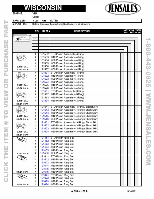
QTYITEM #DESCRIPTIONLETTERED ITEMSINCLUDED IN KIT4 4 4 191532 191533 191534 STD Piston Assembly (4 Ring) .010 Piston Assembly (4 Ring) .020 Piston Assembly (4 Ring)4 191535 .030 Piston Assembly (4 Ring)3.375" OAL 4 191536 .040 Piston Assembly (4 Ring)3-3/32 1-3/16 4 191537 .060 Piston Assembly (4 Ring)4 4 4 191571 191572 191573 STD Piston Assembly (4 Ring) .010 Piston Assembly (4 Ring) .020 Piston Assembly (4 Ring)4 191574 .030 Piston Assembly (4 Ring)3.375" OAL 4 191575 .040 Piston Assembly (4 Ring)3-5/64 1-3/16 4 191576 .060 Piston Assembly (4 Ring)3.375" OAL 4 4 4 4 191591 191592 191593 191594 STD Piston Assembly (3 Ring) .010 Piston Assembly (3 Ring) .020 Piston Assembly (3 Ring).030 Piston Assembly (3 Ring)2-5/64 1-3/164 4 4 191541 191543 191544 STD Piston Assembly (4 Ring / Short Skirt) .020 Piston Assembly (4 Ring / Short Skirt) .030 Piston Assembly (4 Ring / Short Skirt)2.875" OAL 4 191545 .040 Piston Assembly (4 Ring / Short Skirt)3-3/32 1-3/16 4 191546 .060 Piston Assembly (4 Ring / Short Skirt)2.825" OAL 4 4 4 4 191631 191632 191633 191634 STD Piston Assembly (3 Ring / Short Skirt) .010 Piston Assembly (3 Ring / Short Skirt) .020 Piston Assembly (3 Ring / Short Skirt).030 Piston Assembly (3 Ring / Short Skirt)2-5/64 1-3/164 4 191451 191452 STD Piston Ring Set .010 Piston Ring Set4 191453 .020 Piston Ring Set4 191454 .030 Piston Ring Set4 191455 .040 Piston Ring Set3-3/32 1-3/16 4 191456 .060 Piston Ring Set4 4 191611 191612 STD Piston Ring Set .010 Piston Ring Set4 191613 .020 Piston Ring Set4 191614 .030 Piston Ring Set4 191615 .040 Piston Ring Set3-5/64 1-3/16 4 191616 .060 Piston Ring Set4 4 191621 191622 STD Piston Ring Set .010 Piston Ring Set4 191623 .020 Piston Ring Set2-5/64 1-3/16 4 191624 .030 Piston Ring SetAPPLICATION: Balers; Industrial Applications; Skid Loaders; Windrowers;2 4 191566 101276Cylinder Block Assembly (Includes Valve Train)4 291521 STD Rod Bearing4 291522 .010 Rod Bearing4 291523 .020 Rod Bearing8 291456 Connecting Rod Shim, Early Babbitt Rod (.002")1 291524 Main Bearing Assembly, Exc Spec # 390568 (Flywheel End)1 291457 Main Bearing Assembly, Spec # 390568 (Flywheel End)1 291458 Outer Support Bearing Race, Spec # 390568 (Flywheel End)1 291459 Outer Support Needle Brg, Spec # 390568 (Flywheel End)1 291525 Main Bearing Assembly (PTO End)1 291526 Main Bearing Plate Shim (.006" Thick) (1)1 291527 Main Bearing Plate Shim (.013" Thick) (1)1 391456 Main Bearing Plate Gasket (.003" Thick) (1)1 391457 Main Bearing Plate Gasket (.006" Thick) (1)1 391458 Head Gasket Set2 391459 Head Gasket4 391461 Valve Cover Gasket1 391462 Manifold Gasket Set1 391463 Overhaul Gasket Set1 391464 Full Gasket Set w/Seals 1 391465 Pan Gasket Set1 391471 Flywheel Side Gear Cover Crank Seal (1.500 x 2.125 x .312)1 391472 PTO Side Crank Seal (Cork)1 391473 PTO Side Crank Seal Retainer (2)1 391474 PTO Side Crank Seal (Lip Type) (1.437 x 2.686 x .375)1 391475 PTO Seal, Clutch Output Shaft (1.563 x 2.441 x .500) (2)1 391477 PTO Seal, Reduction Output Shaft (1.750 x 2.830 x .374) (2)1 391478 PTO Seal, Shift Shaft (.750 x 1.375 x .406) (2)1 391479 PTO Seal, Shift Shaft (.750 x 1.250 x .250) (2)4 291449 Pin Bushing8 791174 Rod Bolt & Nut 8 791175 Rod Nut30 791176 Head Bolt (1.250")4 791177 Head Bolt (1.375")34 791178 Head Bolt Washer(1)Use Proper Shims & Gaskets To Give .002-.005" End Play (2)Not Included In Gasket Set LETTERED ITEMS INCLUDED IN KIT DESCRIPTION QTY ITEM #QTYITEM # DESCRIPTIONLETTERED ITEMSINCLUDED IN KIT1 591242 Camshaft 1 591243 Thrust Plunger1 591244 Thrust Plunger1 591245 Thrust Button8 591246 Tappet w/Adjusting Screw8 591247 Adjusting Screw4 491365 Exhaust Valve (Stellite / 1.250" Head)4 491366 Intake Valve (1.313" Head)8 491367 Valve Guide (1.813" OAL / .439" OD) 8 491368 Exhaust & Intake Valve Spring: VH4 (2.312" Free Length)4 491369 Ex Valve Spring w/Rotators: VH4D (1.812" Free Length)4 491368 Intake Valve Spring: VH4D (2.312" Free Length)4 491371 Ex Spring, Stellite Valves wo/Rotators (1.969" Free Length)4 491322 Exhaust Rotator: VH4D4 491372 Spring Retainer "8 Used On VH4"16 491273 Keeper Half4 491373 Exhaust Valve Seat (1.125 x 1.375 x .265) 4 491373 Intake Valve Seat (1.125 x 1.375 x .265)APPLICATION: Balers; Industrial Applications; Skid Loaders; Windrowers; 1 591248 Cam Gear, Exc Spec # 3905681 591262 Cam Gear, Spec # 390568 1 591249 Crank Gear, Exc Spec # 3905681 591259 Crank Gear, Exc Spec # 3905681 591261 Crank Gear, Spec # 3905681 591251 Cam & Crank Gear Set, Standard Application1 591252 Idler Gear, Exc Spec # 390568 (37 Tooth w/Bushing) 1 591263 Idler Gear, Spec # 3905681 591253 Idler Gear Bushing, Exc Spec # 3905681 591254 Oil Pump Drive Gear1 591255 Magneto Drive Gear1 591256 Distributor Drive Assembly Drive Gear (3)1 591257 Distributor/Governor Drive Assembly Drive Gear (4) 1 591258 Accessory Drive Assembly Drive Gear1 691185 Oil Pump 1 691186 Oil Pump1 791179 Crankshaft, Standard Direct Drive (5)1 791186 Crankshaft Nut, Flywheel Side (1 1/8-12)4 791183 Connecting Rod (Late Insert Type) (6)2 791184 Cylinder Head1 891221 Fuel Pump, Open Engine (Low Dome)1 891222 Fuel Pump, Power Unit (Rotating Dome & Fuel Inlet Conn) 1 891223 Fuel Pump Plunger Rod (2.750 OAL) "Pumps wo/Primer" 1 891224 Fuel Pump Plunger Cap1 891225 Governor Assembly, wo/Distributor Drive1 891226 Governor Assembly, w/Distributor Drive1 891227 Governor Kit (Weights, Pins, Sleeve/Brg, Seal, Spring +) (7) 1 891228 Governor Kit (Weights, Pins, Sleeve/Brg, Seal, Spring +) (8) 1 891219 Flywheel Ring Gear1 801123 Oil Filter, Thru 3408749 (2.750" x 4 Threads Per Inch) 1 801124 Oil Filter, After 3408749 (2.750" x 5.5 Threads Per Inch) 1 801122 Oil Filter, Late Style (.625" x 18 Threads Per Inch)(3) Used With TF129 Drive Assembly (Drive Housing Does Not Contain Governor)(4) Used With T113 Drive Assembly (Drive Housing Contains Governor)(5) Supply Model, Spec, Serial Number & Number Stamped In Cheek Behind PTO Side Bearing For Correct Shaft(6) Babbitt & Insert Type Rods May Be Mixed In The Same Engine (7)Used On 891225 (8)Used On 891226 LETTERED ITEMS INCLUDED IN KIT DESCRIPTION QTY ITEM #。
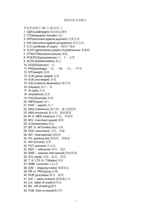
常用外贸术语缩写外贸术语缩写45 个:(很实用)1 C&F(cost&freight) 成本加运费价2 T/T(telegraphic transfer) 电汇3 D/P(document against payment) 付款交单4 D/A (document against acceptance) 承兑交单5 C.O (certificate of origin) 一般原产地证6 G.S.P.(generalized system of preferences) 普惠制7 CTN/CTNS(carton/cartons) 纸箱8 PCE/PCS(piece/pieces) 只、个、支等9 DL/DLS(dollar/dollars) 美元10 DOZ/DZ(dozen) 一打11 PKG(package) 一包,一捆,一扎,一件等12 WT(weight) 重量13 G.W.(gross weight) 毛重14 N.W.(net weight) 净重15 C/D (customs declaration) 报关单16 EA(each) 每个,各17 W (with) 具有18 w/o(without) 没有19 FAC(facsimile) 传真20 IMP(import) 进口21 EXP ( export) 出口22 MAX (maximum) 最大的、最大限度的23 MIN (minimum) 最小的,最低限度24 M 或MED (medium) 中等,中级的25 M/V (merchant vessel) 商船26 S.S(steamship) 船运27 MT 或M/T(metric ton) 公吨28 DOC (document) 文件、单据29 INT (international) 国际的30 P/L (packing list) 装箱单、明细表31 INV (invoice) 发票32 PCT (percent) 百分比33 REF ( reference) 参考、查价34 EMS ( express mail special) 特快传递35 STL.(style) 式样、款式、类型36 T 或LTX 或TX(telex) 电传37 RMB (renminbi) 人民币38 S/M ( shipping marks) 装船标记39 PR 或PRC(price) 价格40 PUR (purchase) 购买、购货41 S/C ( sales contract) 销售确认书42 L/C (letter of credit)信用证43 B/L (bill of lading)提单44 FOB (free on board)离岸价45 CIF (cost,insurance&freight )成本、保险加运费价comprehe nsive package of services 全面的一揽子服务a desig nated ma nned ship 一艘特定的配备船员的船air freight空运货物Airline cooperation 航空公司协作arrival notice 至U货通知as per按照bale or grain capacity 包装或散装容积BALTIME form 波尔的姆格式bank draft银行汇票bareboat charteri ng 光船租船BARECON form贝尔康格式bargaining strenght 讨价还价的能力bill of entry 报关单bills of lading 提单BIMCO波罗的海国际航运运协会blank bill of lading 不记名提单break bulk cargo 杂货,普通货物breakage of pack ing risks 包装破裂险bunker adjustment factor (BAF)燃油价格调整因素;燃油附加费bus in ess corresp ondence 商务通信call at a port 挂靠,停靠cargo transportation 货物运输carriage of goods by sea 海上货物运输carriage of goods by road 公路货物运输carrier承运人carrying capacity 运载能力certificate of registry 登记证书CFR (Cost and Freight) CFR (成本加运费)chargeable weight 计费重量charter party租船合同check list核查单CIF (Cost,lnsuranee and Freight)CIF ( 成本、保险费加运费)CIP (Carriage and In sura nee Paid To)CIP ( 运费、保险费付至)clash and breakage risks 碰损、破碎险class rates等级运价clean bill of lading 清洁提单clear the goods for export 办理货物出口清关手续combined transport 合并运输commissi on age nt 委托代理人com mon carrier公共承运人conference lines 班轮公会运输con sig nee收货人consolidated shipment 集运货物Constructive total loss 推定全损container cargo 集装箱货物containerization 集装箱化con tract of affreightme nt (COA) 包运合同contract of carriage 货物运输合同CPT (Carriage Paid To)CPT (运费付至)lash ing捆扎加固special cargo特殊货物报关单、核销单、提单等的英文翻译出口报关单bill of customs clearanee核销单verification sheet倒签提单antedated B/L直销direct selling传销multi-level selling,pyramid selling唛头mark正唛shipping mark ,main mark, front mark侧唛side markTHC 码头操作费FAF 燃料附加费YAS 码头附加费或者日元升值附加费EPS 是设备位置附加费EXW 工厂交货AIR WAYBILL NUMBER 包裹空运运单号B/L NO 海运的提单M B/L (Ocean Bill of Lading) 海上提单H B/L (House Bill of Lading) 仓库提单报关单英文单词和缩写一.单证( Documents) 进出口业务涉及的单证总的包括三大类:1、金融单证(信用证、汇票、支票和本票)2、商业单证(发票、装箱单、运输单据、保险单等3、用于政府管制的单证(许可证、原产地证明、商检证等)declaration form 报关单nThree steps —declaration, examination of goods andn release of goods, are taken by the Customs to exercise control over general import and export goods. 海关对进出境货物的监管一般经过申报、查验和放行三个环节。
报关单英文单词和缩写一.单证(Documents)进出口业务涉及的单证总的包括三大类:1、金融单证(信用证、汇票、支票和本票)2、商业单证(发票、装箱单、运输单据、保险单等3、用于政府管制的单证(许可证、原产地证明、商检证等)declaration form报关单νThree steps—declaration, examination of goods andν release of goods, are taken by the Customs to exercise control over general import and export goods.海关对进出境货物的监管一般经过申报、查验和放行三个环节。
the person in chargeν of the declarationinvoice发票νocean bill of lading提单νairν waybill空运提单packing list或packing specification(装箱单)νshippingν order(装货单)letter of credit(L|C)(信用证)νinsurance policy(保险单)νsalesν confirmation售货确认书contract(合同)(commodity, quantity, unit price, totalν amount, country of origin and manufacturer, packing, shipping mark, date of shipment, port of shipment, port of destination, insurance, payment, shipment, shipping advice, guarantee of quality, claims, force majeure, late delivery and penalty, arbitration)certificate(commodity inspection certificate商检证animal or plant quarantine certificate 动植物检疫证certificate of origin原产地证二.报关英语常用词汇import进口export出口importν & export corporation(Corp.)importν & export business(enterprise entitled to do import and exportbusiness)export drawback出口退税νimportν & export licenceprocessing with imported(supplied) materials进(来)料加工νbuyer买方seller卖方The buyer requests his bank to issue a letter of credit in favor of the seller. goods(import& export goods , All import and export goods shall be subject to Customs examination)cargo (bulk cargo, cargo in bulk, air cargo, sea cargo, bonded cargo,cargo-ownerWhat cargo is inside the container?The cargo is now released.Commodity(commodity inspection)merchandise泛指商品,不特指某一商品article(smuggled goods and articles, inward and outward goods and articles)luggage 行李物品postal items 邮递物品You don’t have to pay duty on personal belongings, but the other one is subject to duty.means of transport(conveyance)运输工具(vessel, aircraft, train, vehicle):All inward and outward means of transport shall be subject to Customs control on arriving in or departing from the Customs territory.ocean vessel船名packing(bag袋, bale包,bottle, coil圈,case, crate板条箱,dozen, package 件:total packages合计件数, piece, roll, set, unit辆,台,单位,drum桶,carton 纸箱, wooden cases木箱,pallet托盘,container ,in bulk)weight重量gross weight毛重net weight净重tare皮重quantity数量:The minimum quantity of an order for the goods is 500 cases. description of goods货名name and specifications of commodity品名及规格type类型mode (term)of trade贸易方式name of trading country贸易国date of importation进口日期value价值total value of the contract commercial value, duty-paying valueThe duty-paying value of an import item shall be its normal CIF price and the duty-paying value of an export item shall be its FOB price, minus the export duty.The duty-paying value of an inward or outward article shall be fixed by the Customs.price价格unit price单价total price总价total amount总价consignor发货人consignee收货人While the examination is being carried out, the consignee of the import goods or the consignor of the export goods shall be present and responsible for moving the goods, opening and restoring the packingDeclaration of import goods shall be made to the Customs by the consignee within 14 days of the declaration of the arrival of the means of transport; declaration of export goods shall be made by the consignor 24 hours prior to the loading unless otherwise approved by the Customs. 进口货物的收货人应当自运输工具申报进境之日起14日内,出口货物的发货人除海关特准的外应当在货物运抵海关监管区后装货的24小时以前,向海关申报。
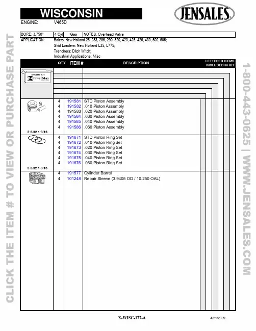
Skid Loaders: New Holland L35, L775;Trenchers: Ditch Witch;QTYITEM # DESCRIPTION LETTERED ITEMSINCLUDED IN KIT4 4 4 191581 191582 191583 STD Piston Assembly .010 Piston Assembly .020 Piston Assembly4 191584 .030 Piston Assembly4 191585 .040 Piston Assembly4 191586 .060 Piston Assembly3-3/32 1-3/164 4 191671 191672 STD Piston Ring Set .010 Piston Ring Set4 191673 .020 Piston Ring Set4 191674 .030 Piston Ring Set4 191675 .040 Piston Ring Set4 191676 .060 Piston Ring Set3-3/32 1-3/164 191577 Cylinder Barrel4 101248 Repair Sleeve (3.9405 OD / 10.250 OAL)APPLICATION: Balers: New Holland 25, 283, 286, 290, 320, 420, 425, 426, 430, 500, 505;Skid Loaders: New Holland L35, L775;Trenchers: Ditch Witch;4 291536 STD Rod Bearing4 291537 .010 Rod Bearing4 291538 .020 Rod Bearing4 291539 .030 Rod Bearing2 291519 Main Bearing Assembly (Flywheel & PTO End)1 291545 STD Center Main Bearing, After 49046561 291546 .001 Center Main Bearing, After 49046561 291547 .010 Center Main Bearing, After 49046561 291548 .020 Center Main Bearing, After 49046562 791235 Center Main Bearing Hanger Attaching Bolts (Grade 8)1 291528 Main Bearing Plate Shim (.014" Thick) (1)1 391514 Main Bearing Plate Gasket (.003" Thick) (1)1 391515 Main Bearing Plate Gasket (.006" Thick) (1)1 391516 Head Gasket Set4 391517 Head Gasket4 391518 Valve Cover Gasket1 391519 Manifold Gasket Set (14 Port Gaskets & Inserts)1 391522 Overhaul Gasket Set1 391523 Full Gasket Set w/Seals1 391487 Pan Gasket Set1 391525 Flywheel Side Gear Cover Crank Seal (2.000 x 2.996 x .375)1 391526 PTO Side Crank Seal (2.000 x 3.000 x .312)4 291469 Pin Bushing8 791221 Rod Bolt 8 791194 Rod Nut3 791222 Head Stud (8.375")1 791223 Head Stud (8.687")8 791224 Head Stud (10.000")4 791225 Head Stud (11.312")16 791226 Head Nut4 791227 Valve Cover Bail Wire(1)Use Proper Shims & Gaskets To Give .002-.005" End PlayLETTERED ITEMS INCLUDED IN KIT DESCRIPTION QTY ITEM #Skid Loaders: New Holland L35, L775;Trenchers: Ditch Witch;QTY ITEM # DESCRIPTION LETTERED ITEMSINCLUDED IN KIT1 591292 Camshaft1 591243 Thrust Plunger1 591244 Thrust Plunger Spring1 591245 Thrust Button8 591293 Tappet4 491382 Exhaust Valve4 491383 Intake Valve8 491384 Valve Guide8 491371 Valve Spring4 491385 Exhaust Rotator4 491386 Intake Spring Retainer16 491387 Keeper Half4 491373 Exhaust Valve Seat (1.125 x 1.375 x .265)4 491388 Intake Valve Seat (1.375 x 1.625 x .250)4 491389 Exhaust Rocker Arm4 491391 Intake Rocker Arm4 491392 Rocker Arm Shaft4 491393 Rocker Arm Shaft Spring4 491396 Rocker Arm Assembly, Thru 54878164 491394 Rocker Arm Assembly, After 5487816 (4)APPLICATION: Balers: New Holland 25, 283, 286, 290, 320, 420, 425, 426, 430, 500, 505;Skid Loaders: New Holland L35, L775;Trenchers: Ditch Witch;1 591295 Cam Gear, Thru 50757751 591272 Cam Gear, After 5075775 1 591296 Crank Gear, Thru 50757751 591294 Crank Gear, After 50757751 591297 Idler Gear, Thru 50757751 591275 Idler Gear, After 50757751 591253 Idler Gear Bushing1 591254 Oil Pump Drive Gear, After 50757751 591298 Governor Drive Gear, Thru 50757751 591278 Governor Drive Gear, 5075776-53568051 591277 Governor Drive Gear, After 53568051 591299 Accessory Drive Assembly Drive Gear, Thru 50757751 591281 Accessory Drive Assembly Drive Gear, After 50757758 591311 Push Rod, Thru 5487816 (10.937" Long)8 591312 Push Rod, After 5487816 (11.219' Long)8 591315 Push Rod Tube1 691191 Oil Pump1 691192 Oil Pump Screen1 691194 Pressure Relief Valve Assembly1 791232 Crankshaft, Standard After 4904656 (5)1 791233 Crankshaft Nut, Flywheel Side (1 1/2-12)4 791229 Connecting Rod, Thru 92051190 (6)4 791231 Connecting Rod, After 92051190 (6)4 791228 Cylinder Head1 891241 Fuel Pump (Low Dome)1 891242 Fuel Pump Plunger Rod1 891224 Fuel Pump Plunger Cap1 891243 Governor Kit (Weights, Pins, Sleeve/Brg, Seal, Spring +)1 891234 Flywheel Ring Gear1 801125 Oil Filter(5)Supply Model, Spec, Serial Number & Number Stamped In Cheek Behind PTO Side Bearing For Correct ShaftLETTERED ITEMS INCLUDED IN KITDESCRIPTION QTY ITEM #。
LINC84T-10, 11, 12, & 14 Series Chemical Metering PumpPneumatic PlungerTo Order, Call 800.455.LINCOr FAX your order anytime to215.293.0498For the Nearest AuthorizedRepresentative:By Telephone: 800.455.LINC forthe US & Canada, 215.293.0465 or215.441.0800 for InternationalcustomersBy Fax:215.293.0498E-mail:************************Technical SupportBy Telephone: 800.455.LINC or215.293.0498By E-mail:******************Convenient HoursOur phone lines are open Monday– Friday 8:00 AM – 4:45 PM (EST)LINC WarrantyThree year limited warranty on all ourproducts against defects in materials.LINC Technical SupportTechnical service and supportbegins with an easy toll-free call.Many times, our experiencedcustomer service reps can isolateand resolve problems over thephone or provide a referral to ourauthorized representatives nation-wide.We also offer factory repairservices with facilities in Ivyland,PA. if a warranty issue that cannotbe resolved locally.Purchase OrdersAll mail-in purchase orders mustbe signed by an authorizedperson.When ordering please list:•Quantity•Description of Items•Shipping Address•Billing Address•Purchase Order NumberRequest for Quotation – RFQ’sPlease send RFQ’s to:By Mail:Linc Milton RoyAttn: Customer Service201 Ivyland RoadIvyland, PA 18974USABy Fax:1.215.293.0498By E-mail:************************Freight ChargesAll shipments are F.O.B., Ivyland,PA, USA. Shipping and handlingare included on the invoice,prepay and add.TermsWith credit approval, net 30 days.Contents - 84T-10, 11, 12, & 14 Pump Manual.......................................................................................................Page General Specifications.. (4)Selection Chart (4)Ordering Chart (5)How to Determine Supply Pressure (6)Scope Of This Manual (7)Installation (7)Maintenance (7)Removing the Pump from Service (7)Timer (7)Suction Check Valve (8)Discharge Check Valve (8)Piston/Plunger (9)Plunger Seal (9)Reassembling The Pump (9)Assembly Drawings & Parts ListsFigure 1, 84T-10, 11, & 14 Assembly Drawing (10)Pump Assembly Parts List: 84T-10, 11, & 14 (11)Seal Materials 84T-10, 11, & 14 Parts List............................................................................................... 12 & 13F igure 2, 84T-12 Assembly Drawing (14)Pump Assembly Parts List: 84T-12 (15)Seal Materials 84T-12 Parts List (16)Figure 3, Timer (17)F igure 4, Discharge Check Valve (One Piece Body) (18)Figure 5, Discharge Check Valve (Two Piece Body) (18)Figure 6, Suction Check Valve (19)Suction Check Valve Parts List (20)LINC Chemical Pump Gas Consumption Chart (21)Notes:1.Maximum rates are based on maximum strokes per pump.2.Minimum rates are calculated as follows:3/16", 1/4" and 1/2" plunger pumps are 1/4" stroke length and a minimum of 4 strokes per minute.1" plunger pumps are 1/4" stroke length and a minimum of 4 strokes per minute.3.The timer supply pressure is 15 to 110 psi.4.When creating a Model Number using the Ordering Chart, the "X" in the Model Number column abovewill be replaced by a single digit representing the plunger seal selection. The plunger seal is shown in the Ordering Chart.5.Maximum pressure based on 100 psi supply pressure.6.Volume per stroke in shown for maximum pressure and strokes per minute. Volume per stroke increases as dischargepressure decreases.Ordering Chart: LINC 84T-10, 11, 12 & 14 Pneumatic Plunger Metering PumpSeries:84T-Pneumatic, plunger type metering pumpPlunger Diameter/Pump Control:10-3/16" plunger diameter (17-4 ss ceramic coated only), timer only11-1/4" plunger diameter, timer only12-1/2" plunger diameter, timer only14-1" plunger diameter, timer onlyPlunger Seal:1-Packing mechanical seal - Fluorocarbon, wetted o-rings - Fluorocarbon2-Packing mechanical seal - Fluoromyte, wetted o-rings - TFE3-Packing mechanical seal - Nitrile, wetted o-rings - Nitrile4-Packing mechanical seal - TFE/Graphite, wetted o-rings - TFE5-Specify your requirements6-Packing mechanical seal - Ultra High Molecular Weight Polyethylene,wetted o-rings - TFE7-O-rings packing seal - Fluorocarbon, wetted o-rings - Fluorocarbon8-O-rings packing seal - Nitrile, wetted o-rings - Nitrile9-O-rings packing seal - Kalrez, wetted o-rings - KalrezPiston Size:1- 2 1/4" piston diameter2-3" piston diameter4-4" piston diameterOther:4-Ceramic5-Specify your requirements9-All 316 ss pump/timer (when required)Option Number:( )-Factory will assign an option number based on specified requirements.Note:If no further requirements are desired, omit "other" options codesfrom the part number. Example 84T-11-41.LINC 84T- ____-_______ ( )Example: LINC 84T-11-41 Pneumatic Metering PumpScope Of This Manual:This manual describes and pro-vides instructions and parts list forthe LINC84T-10, 11, 12 & 14 Se-ries Chemical Metering Pump. Thispump is a pneumatically operatedplunger pump.1.Figure 1 of this manual is thesectional drawing and partslist for the LINC84T-10, 11 &14 Chemical Metering Pump.2.Figure 2 of this manual is thesectional drawing and partslist for the LINC84T-12Chemical Metering Pump.Installation:The LINC84T-10, 11, 12 & 14 re-quire a flooded suction and mustbe located lower than the chemicalsupply tank. Vertical installationof the piston housing is required.1.Connect the suction linethrough a filter or strainer tothe suction check valve (fig.1, item 17 or fig. 2, item 16).2.Connect the discharge line tothe desired location.Note: An in-line check valve at thepoint of injection is recommendedto prevent back flow to the pumpduring shutdown or servicing.3.Connect a supply pressureline to the timer (fig. 1, item 1or fig. 2, item 1). Air is therecommended supply; how-ever, any dry filtered gas maybe used. The supply pressureto the timer must be regu-lated between 15 psig and110 psig.4.Set the regulator to the properpressure to overcome thedischarge pressure requiredby the pump. Refer to theparagraph on "AmplicationRatio" in this manual todetermine the correct supplypressure.5.To prime the pump, loosenthe bleed screw (fig. 1, item18 or fig. 2, item 18). Allowthe liquid (chemical) to flowinto the pump chamber,venting the trapped air or gas.Tighten the bleed screw.6.Start the pump and run for aminimum of one minute.Open the bleed screw againand evacuate all the remain-ing air or gas from the pumpchamber.ing a rate gauge, set thedesired pumping rate byadjusting the timer knob andstroke adjustment screw.The timer can be set to strokethe pump from 4 strokes/minute to the maximum ratefor the particular pump beingused. See selection chart inthis section of the manual.8.The stroke length is adjustedby rotating the stroke adjust-ment screw (fig. 1, item 5 orfig. 2, item 4) on top of thepiston housing (fig. 1, item 8or fig. 2, item 6). Loosen thejam nut and adjust the strokeadjustment screw as neces-sary (fig. 1, item 4 or fig. 2,item 5). Lock down the jamnut after any adjustments aremade.Note: The minimum stroke on the84T-10, 11 & 12 is 1/8" and 1/4" onthe 84T-14.Maintenance:Refer to all sectional drawing andparts list in this manual. All repairsshould be performed in a cleanenvironment.The following steps must betaken before proceeding with anymaintenance operations:Removing the Pump from Ser-vice:1.Rotate the control knob onthe timer to the "O" position.2.Disconnect the supplypressure from the timer.3.Close the upstream anddownstream valves on thechemical lines.4.Open the bleed screw torelease the pressure in thepump.5.Disconnect the suction anddischarge lines from thecheck valves.Timer, Figure 1, item 1 or Figure2, item 1 & Figure 3:1.Disconnect the supplypressure from the timer.2.Rotate the timer counter-clockwise on the pipe nipplethat connects it to the pistonhousing until the timer isvertical with the supply pres-sure port pointing down.3.Loosen and remove the twoscrews from the timer (fig. 3,item 1).4.Separate the three timer sec-tions and discard the seal,diaphragm and the disc (fig.3, items 4, 6 & 15). Be care-ful not to lose the small discspring (fig. 3, item 16). Notethe orientation of thediaphragm as it is removed.5.Loosen the set screw on theknob (fig. 3, item 11).Remove the knob and knobspring (fig. 3, item 9).6.Unscrew the adjustmentscrew (fig. 3, item 10) fromthe front body (fig. 3, item 13).Remove and discard the o-ring (fig. 3, item 12).7.Reassemble the timer inreverse order of the abovesteps, using new rubberparts. Lubricate the adjust-ment screw threads and itso-ring. No other lubricationis required.8.After installing the adjust-ment screw, turn it in by handwithout the knob installeduntil it lightly seats. Duringthis operations do not over-tighten the adjustment screwinto its seat. Apply supplypressure to the timer andunscrew the adjustmentscrew slowly until the pumpstarts to run. Trial and errorwill be necessary to deter-mine the proper orientation ofthe knob on the adjustmentscrew. Once the properorientation is determined, re-install the knob spring andknob.Suction Check Valve,Figure 1, item 17 or Figure 2, item16 & Figure 6:1.Disconnect the piping fromthe check valve.2.Unscrew the check valvebody from the pump (fig. 6,item 1).3.Remove and discard the o-rings (fig. 6, items 3 & 4).4.Inspect the ball for damage(fig. 6, item 2). Replace ifnecessary. Reassemble thecheck valve using new o-rings.If the seat o-ring is Teflon,install it onto the checkvalve body and "peen" theball into the seat to ensureproper sealing (fig. 6, item 3).5.Install the repaired suctioncheck valve into the pumpbody. Tighten securely.Discharge Check Valve,Figure 1, item 16 or Figure 2, item15 & Figure 4:1.Disconnect the piping fromthe check valve.2.Unscrew the check valvebody from the pump (fig. 4,item 1).3.Remove and discard the o-rings (fig. 4, items 4 & 5).4.Inspect the ball and spring fordamage (fig. 4, items 2 & 3).Replace if necessary. Reas-semble the check valve usingnew o-rings. If the seato-ring is Teflon, install it intothe pump body assemblyand "peen" the ball onto theseat to ensure proper sealing.5.Install the repaired dischargecheck valve into the pumpbody. Place the ball on theo-ring seat followed by thespring (small end of thespring toward the ball) andscrew the discharge checkvalve body into the pumpbody assembly. Tighten se-curely.Discharge Check Valve,Two-Piece, Model 84T-14 only,Figure 1, item 16 & Figure 5:1.Separate the two halves ofthe check valve (fig. 5, items1 & 4).2.Replace the o-rings, ball andspring as required (fig. 5,items 2, 3, 5 & 6). The Teflono-ring may be removed,turned around and reused ifa new o-ring is not available(fig. 5, item 2). During thisprocedure extreme careshould be exercised. Theball should be "peened" onthe Teflon seat to ensureproper sealing (fig. 5, items1, 2 & 5).3.Ensure that the proper flowdirection, as marked on thevalve body is observed wheninstalling or replacing thischeck valve.Piston/Plunger:1.Secure the pump bodyassembly in a vise (fig. 1,item 19 or fig. 2, item 17).2.Remove the piston housingscrews (fig. 1, item 11 or fig.2, item 10). Grasp thepiston housing and pull up toremove (fig. 1, item 8 or fig.2, item 6).3.Grasp the piston and pullaway from the pump bodyasssembly to remove (fig. 1,item 6 or fig. 2, item 7).Inspect the plunger for wear,especially longitudinalgrooves. Replace the pistonassembly if necessary. In-spect the piston u-cup (fig. 1,item 7 or fig. 2, item 8).Replace if necessary.6.Remove the spring, lubricantseal back-up and lubricantseal from the spring cavity(fig. 1, items 9,12, & 13 or fig.2, items 9, 11 & 12).Inspect all three parts, espe-cially the lubricant seal andreplace worn or damagedparts as needed.Plunger Seal,Figure 1, item15 or Figure 2, item 14:1.With a pipe or strap wrench,separate the pump bodyassembly (fig. 1, item 19 orfig. 2, item 17).2.Remove the seal back-upand plunger seal (fig. 1,item 15 or fig. 2, item 14) fromthe lower housing of thepump body assembly. Notethat on Model 84T-12, theplunger seal and plungerseal backup are in the upperhousing of the pump bodyassembly (fig. 2, items 14).Carefully remove the sealback-up and seal. Inspect forwear or deterioration frombeing attacked by the chemi-cal the pump is pumping.3.Replace the plunger seal. Ifneeded, also replace theplunger seal back-up. Extremecare should be taken not toscratch or distort these parts.Reassemble the Pump:1.Lubricate the piston u-cupand plunger with light oil toprotect against possibledamage during assembly.2.Reassemble the piston/plunger assembly, whichincludes the lubricant seal,lubricant seal back-up andspring and install into thepump body assembly. SeeFigure 1 or Figure 2 forcorrect assembly.3.Replace the piston housingand secure with the pistonhousing screws.4.Thread the timer connectingnipple into the port at the topof the piston housing. Threadthe output port in the rearbody of the timer to thisnipple.Caution: Be sure there are noleaks at these connections. If leaksare present, the timer will not oper-ate properly.6.Install the new plunger sealand plunger seal back-upSee the procedure entitled"Plunger Seal" above.7.Screw the upper part of thepump body assembly backinto the lower part and tightensecurely.8.If the bleed screw has beenremoved, install and tightensecurely.Plunger and Plunger SealLubrication:1.Remove the plug from thepump body (fig. 1, item 14 orfig. 2, item 13).2.Add silicone base lubricant(Dow Dorning DC-7, part#10354) or equal into the portwhere the plug was removed.Approximately 0.5 cc will berequired for each refill.Replace the plug.Note: Do not use a grease gunor any metal tool to insert thelubriant into the pump to preventdamage to the plunger or plungerseal.3.Silicone lubricant should beadded every 4 - 6 weeksdepending upon operationconditions.Figure 1, LINC84T-10, 11, & 14 Series PumpLINC84T-10, 11, & 14 Series Parts ListSeries 84T-10, 11 & 14 Seal MaterialsModel 84T-11-22Item Description Part #Material15A........................................Plunger Seal.........................................................21197....................................Fluoromyte 15B........................................Plunger Seal Back-Up..........................................22571....................................Acetal16..........................................Discharge Check Assembly.................................22626....................................See Parts17..........................................Suction Check Assembly......................................24777....................................See Parts Model 84T-11-42Item Description Part #Material15A........................................Plunger Seal.........................................................11283....................................TFE/Graphite 15B........................................Plunger Seal Back-Up..........................................22581....................................Peek16..........................................Discharge Check Assembly.................................22626....................................See Parts17..........................................Suction Check Assembly......................................24777....................................See Parts Model 84T-11-62Item Description Part #Material15A........................................Plunger Seal.........................................................13007....................................UHMWPE16..........................................Discharge Check Assembly.................................22626....................................See Parts17..........................................Suction Check Assembly......................................24777....................................See Parts Model 84T-14-14Item Description Part #Material15A.........................................Plunger Seal............................................................115 8 7....................................Fludrocarbon 15B.........................................Plunger Seal Back-Up...............................................23551......................................Acetal16..........................................Discharge Check Assembly.................................24753....................................See Parts17...........................................Suction Check Assembly..........................................24165......................................See Parts Model 84T-14-44Item15A........................................Plunger Seal...........................................................11590.....................................TFE/Graphite 15B.........................................Plunger Seal Backup.................................................23551......................................Acetal16...........................................Discharge Check Assembly......................................24753......................................See Parts17...........................................Suction Check Assembly..........................................24165......................................See Parts Model 84T-14-64Item Description Part #Material15A........................................Plunger Seal...........................................................131 4 3...................................UHMWPE15B........................................Plunger Seal Back-Up..........................................23551....................................Acetal16..........................................Discharge Check Assembly.................................24753....................................See Parts17..........................................Suction Check Assembly......................................24165....................................See Parts Series 84T-10, 11 & 14 Seal MaterialsPage 14 •Figure 2, 84T-12 Series PumpLINC84T-12 Series Parts ListLINC84T-12 Series Seal MaterialsFigure 3,TimerReference fig. 1, item 1Reference fig. 2, item 1Page 18 •Figure 4, Discharge Check ValveOne Piece BodyReference fig. 1, item 16Reference fig. 2, item 15Figure 5, Discharge Check Valve Two Piece Body Reference fig. 1, item 16Model 84T-14 OnlyFigure 6,Suction Check ValveOne Piece BodyReference fig. 1, item 17Reference fig. 2, item 16For Model 84T-11 & 84-12For Model 84T-14 OnlyPage 20•LINC Chemical PumpGas Consumption T ableACTUATION PISTON DIA. (IN)>> 1.50 2.2534446810 > >SPRING SPRING SPRING SPRING SPRING GAS GAS GAS GAS CONFIGURATION RETURN RETURN RETURN RETURN RETURN RETURN RETURN RETURN RETURN > >NO RELAY NO RELAY NO RELAY NO RELAY INCLUDING INCLUDING INCLUDING INCLUDING INCLUDINGRELAY RELAY RELAY RELAY RELAY SUPPLY VOLUME DISPLACED BY PISTON FOR 1" STROKE(CUBIC FEET)PRESS.0.001022650.002300970.004090620.007272210.007272210.014544410.032724920.058177640.09090257 (PSI)THEORETICAL GAS CONSUMPTION FOR EACH 1" STROKE (SCF)00.00000.00000.00000.00000.00000.00000.00000.00000.0000100.00170.00390.00690.01220.01220.02440.05500.09780.1527200.00240.00540.00970.01720.01720.03430.07720.13730.2146300.00310.00700.01240.02210.02210.04420.09950.17690.2764400.00380.00860.01520.02710.02710.05410.12180.21650.3383500.00450.01010.01800.03200.03200.06400.14400.25610.4001600.00520.01170.02080.03700.03700.07390.16630.29560.4619700.00590.01330.02360.04190.04190.08380.18860.33520.5238800.00660.01480.02640.04680.04680.09370.21080.37480.5856900.00730.01640.02910.05180.05180.10360.23310.41440.64741000.00800.01800.03190.05670.05670.11350.25530.45390.70931100.00870.01950.03470.06170.06170.12340.27760.49350.77111200.00940.02110.03750.06660.06660.13330.29990.53310.83301300.01010.02260.04030.07160.07160.14320.32210.57270.89481400.01080.02420.04300.07650.07650.15310.34440.61230.95661500.01150.02580.04580.08150.08150.16300.36670.6518 1.0185LINC Milton Roy. represents and warrants that for a period of 3 years from receipt of the product: (1) the product will be free from defects in materials and workmanship; and (2) the product will perform substantially in accordance with product manuals, literature, or documentation. Any written or oral information or advice given by LINC Milton Roy representatives, agents, or employees will in no way increase the scope of this warranty. If the product fails to comply with the warranty set forth herein, LINC Milton Roy's entire liability and the customer's exclusive remedy will be replacement of the product(s) or, at LINC Milton Roy's option, LINC Milton Roy's reasonable effort to make the product meet the warranty set forth herein. LINC Milton Roy disclaims all other warranties, either expressed or implied, including but not limited to, implied warranties or merchantability and fitness for a particular purpose, with respect to the product. This limited warranty gives you specific legal rights. You may have others, which vary from state to state. These remedies are not available outside of the United States and Canada. In no event shall LINC Milton Roy or its suppliers be liable for any damages whatsoever (including, without limitation, damages for loss of profits, business interruption, loss of information, or other pecuniary loss) arising out of the use of or inability to use the product, even if LINC Milton Roy has been advised of the possibility of such damages. Information contained in this document is subject to change without notice and does not represent a commitment on the part of LINC Milton Roy. All prices quoted are in U.S. dollars, F.O.B. Ivyland, PA. LINC, LINC Chemical Pumps, and LINC Level & Flow Switches are trademarks of LINC Milton Roy. All other product names and/or registered trademarks are the property of their respective holders. LINC Milton Roy support services are subject to LINC Milton Roy's then-current prices, terms, and conditions, which are subject to change without notice. All prices and specifications, if published, are subject to change without notice.。
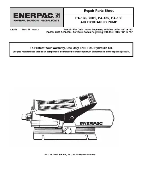
L1252 Rev. M 02/13 PA135 - For Date Codes Beginning with the Letter “A” or “B”PA133, 7001 & PA136 - For Date Codes Beginning with the Letter “C” or “D”PA-133, 7001, PA-135, PA-136 Air Hydraulic PumpTo replace an early style air piston assembly:Remove early style style air piston (item 54A) and U-Cup seal (item 55A) from openend of air motor (item 1). These parts will not be reused and can be discarded.If not pre-installed, install O-Ring (item 56) and Glyd Ring (item 55B), into groove onnew style air piston (item 54B).Apply grease to Glyd Ring (item 55B).Install new style air piston assembly (items 54B, 55B and 56) through open end ofair motor (item 1).54B5655BEarly Style Air Piston54A 55ANOTE: Reservoir fill plug, Item 32, should be HAND TIGHTENED only. Do not use a pliers or wren h. Over-tightening will tear the reservoir bladder. Oil leaking out of the vent hole loc ated at the rear of the reservoir is an indication of a torn bladder.NOTE: Relief Valve, Item 2L, is fac tory set for maximum pressure ac c ording to pump model. DO NOT adjust to a higher pressure.When setting the relief valve, it should only be adjusted up to the desired pressure setting. To insure that the internal relief valve setting is co rrect,check the model number when servicing the product. The setting may n the pressure setting designated by the NOTE: Assemble ball guide, Item 2G, with outside c hamfer fac ing ball seat, Item 2D).NOTE: Closed end of spring, Item 2EE, must go toward the bottom of the hole.NOTE: Torque Coupling V-Retainer, Item 2N, to 30-40 in-lbs.NOTE: Torque Item 7, 23, and 24 to 25 ft-lbs.NOTE: Torque Item 6 to 75 ft-lbs.Figure 1, PA133, 7001, PA135, PA136 Air Hydraulic PumpSectional View -Assembly of items 55B and 56.Sectional View items 54B, 55B and 56.See note below forItem 2L.12345678910Figure 2, Release Plunger1 ★ 1 Back-Up Washer2 ★ 1 O-Ring3 ★ 1 O-Ring4 ★ 1 Back-Up Washer5 DA5290900SR1 1 Release Guide Assembly6 ★ 1 Retaining Ring7 DA4848108 1 Spring Washer 8 ★ 1 Cap9 DA48320401Release Plunger10★ 1 Spring★ I ndicates items included in and available only as part of Release Plunger KitDA4832040KR. NOTE: T he Release Plunger Repair Kit (DA4832040KR) and Release GuideAssembly (DA5290900SR1) also include items 2BB, 2CC, 2E, 2EE, 2Z, and 10 from the Air Pump Assembly (Figure 1).N OTE: Repair Kit PA133K3 includes (1) DA4832040KR.NOTE: P umps manufactured prior to November 1991 have a release plungerassembly that uses a roller in place of the cap now being used. The roller (CB923281), dowel pin (CH200061), and spring washer (CH198108) are available for service in Roller Replacement KitCB923281SR. To replace the release plunger or release body, order a complete assembly (DA5290900SR1).Repair Parts List for Figure 2ItemPart Number Qty. Description1876542345Figure 3, Swivel Coupler Assembly85, 5A72, 2A4136Figure 4, Relief Valve Assembly1 A8005007 1 Plug2 ★ 1 Spring (PA133 & PA135) 2A ★ 1 Spring (PA136) 3 ★ 1 O-Ring4 ★ 1 O-Ring5 CH202950SR 1 Release Valve Assembly(PA133 & PA135) 5A CH207950SR 1 Release Valve Assembly (PA136) 6 L86028 1 Set Screw 7 CH180950W 1 Ball Guide Assembly 8★ 1 Plug★ I ndicates items included in and available only as part of Relief Valve RepairKit CH202950K.NOTE: T he Relief Valve Repair Kit also includes Items 9 and 10 from the AirPump Assembly, Figure 1.NOTE: R elief Valve Repair Kit CH202950K contains two sizes of springs (item2/2A). Use the spring from the kit that matches the spring removed from the relief valve.NOTE: Repair Kit PA133K3 includes (1) CH202950K.NOTE: R elief valve adjustments should only be performed by an EnerpacAuthorized Service Center utilizing prescribed procedures and proper test equipment.Repair Parts List for Figure 4ItemPart Number Qty. DescriptionApply one drop of Loc tite #242 to threads or stake threads in Item 7 in only one plac e after assembly.1346725Figure 5, Hydraulic CylinderM odel PA133, 70011 ★ 1 Spring2 CH203950SR 1 Hydraulic Cylinder Assembly3 ★ 1 O-Ring4 ★ 1 Back-Up Washer5 ★ 1 U-Cup6 ★ 1 Back-Up Bearing7 ★ 1 Bearing Retainer Model PA135 1 ★ 1 Spring 2 DA1227950SR 1 Hydraulic Cylinder Assembly 3 ★ 1 O-Ring 4 ★ 1 Back-Up Washer 5 ★ 1 U-Cup 6 ★ 1 Back-Up Bearing 7 ★ 1 Bearing Retainer Model PA136 1 ★ 1 Spring 2 CH208950W 1 Hydraulic Cylinder Assembly 3 ★ 1 O-Ring 4 ★ 1 Back-Up Washer 5 ★ 1 U-Cup 6 ★ 1 Back-Up Bearing 7 ★ 1 Bearing Retainer ★ I ndicates items included in and available only as part of Hydraulic Cylinder Repair Kit HCRK1.NOTE: H CRK1 is a universal kit and will service any of the three hydrauliccylinders listed.NOTE: H ydraulic Cylinder Repair Kit HCRK1 also includes Items 2D, 2E, and10 from the Air Pump Assembly (Figure 1).NOTE: Repair Kit PA133K3 includes (1) HCRK1.Repair Parts List for Figure 5ItemPart Number Qty. DescriptionAustralia and New Zealand Actuant Australia Ltd.Block V Unit 3Regents Park Estate391 Park RoadRegents Park NSW 2143(P.O. Box 261) AustraliaT +61 (0)2 9743 8988F +61 (0)2 9743 8648********************BrazilPower Packer do Brasil Ltda.Rua Luiz Lawrie Reid, 54809930-760 - Diadema (SP)T +55 11 5687 2211F +55 11 5686 5583TollFree************************************ CanadaActuant Canada Corporation6615 Ordan Drive, Unit 14-15 Mississauga, Ontario L5T 1X2T +1 905 564 5749F +1 905 564 0305Toll Free:T +1 800 268 4987F +1 800 461 2456**************************** ChinaActuant (China) Industries Co. Ltd. No. 6 Nanjing East Road,Taicang Economic Dep Zone Jiangsu, ChinaT +86 0512 5328 7500F +86 0512 5335 9690Toll Free: +86 400 885 0369********************France, Switzerland, North Africa and French speaking African countriesENERPACUne division d’ACTUANT France S.A. ZA de Courtaboeuf32, avenue de la Baltique91140 VILLEBON /YVETTEFranceT +33 1 60 13 68 68F +33 1 69 20 37 50********************Germany and AustriaENERPAC GmbHP.O. Box 300113D-40401 DüsseldorfWillstätterstrasse 13D-40549 Düsseldorf, GermanyT +49 211 471 490F +49 211 471 49 28********************IndiaENERPAC Hydraulics Pvt. Ltd.No. 1A, Peenya Industrial AreaIInd Phase, Bangalore, 560 058, IndiaT +91 80 40 792 777F +91 80 40 792 792********************ItalyENERPAC S.p.A.Via Canova 420094 Corsico (Milano)T +39 02 4861 111F +39 02 4860 1288********************JapanApplied Power Japan LTD KKBesshocho 85-7Kita-ku, Saitama-shi 331-0821, JapanT +81 48 662 4911F +81 48 662 4955********************Middle East, Egypt and LibyaENERPAC Middle East FZEOffice 423, LOB 15P.O. Box 18004, Jebel Ali, DubaiUnited Arab EmiratesT +971 (0)48872686F +971 (0)48872687********************RussiaRep. office EnerpacRussian FederationAdmirala Makarova Street 8125212 Moscow, RussiaT +7 495 98090 91F +7 495 98090 92********************Southeast Asia, Hong Kongand TaiwanActuant Asia Pte Ltd.83 Joo Koon CircleSingapore 629109T +65 68 63 0611F +65 64845669Toll Free: +1800 363 7722********************South KoreaActuant Korea Ltd.3Ba 717, Shihwa Industrial ComplexJungwang-Dong, Shihung-Shi,Kyunggi-DoRepublic of Korea 429-450T +82 31 4344506F +82 31 4344507********************Spain and PortugalENERPAC SPAIN, S.L.Avda. Los Frailes, 40 – Nave C & DPol. Ind. Los Frailes28814 Daganzo de Arriba(Madrid) SpainT +3491 88486 06F +3491 88486 11********************Sweden, Denmark, Norway, Finlandand IcelandEnerpac Scandinavia ABFabriksgatan 7412 50 GothenburgSwedenT +46 (0) 31 799 0281F +46 (0) 31 799 0010*********************************The Netherlands, Belgium,Luxembourg,Central and Eastern Europe,Baltic States, Greece, Turkeyand CIS countriesENERPAC B.V.Galvanistraat 1156716 AE EdeP.O. Box 80976710 AB EdeThe NetherlandsT +31 318 535 911F +31 318 535 848********************Enerpac Integrated Solutions B.V.Opaalstraat 447554 TS HengeloP.O. Box 4217550 AK HengeloThe NetherlandsT +31 74 242 20 45F +31 74 243 03 38*******************************South Africa and other Englishspeaking African countriesEnerpac Africa Pty Ltd.No. 5 Bauhinia AvenueCambridge Office ParkBlock EHighveld Techno ParkCenturion 0157South AfricaT: +27 12 940 0656United Kingdom and IrelandENERPAC Ltd.,Bentley Road SouthDarlaston, West MidlandsWS10 8LQEnglandT +44 (0)121 50 50 787F +44 (0)121 50 50 799********************USA, Latin America and CaribbeanENERPACP.O. Box 3241Milwaukee WI 53201 USAT +1 262 293 1600F +1 262 293 7036User inquiries:T +1 800 433 2766Distributor inquiries/orders:T +1 800 558 0530F +1 800 628 0490Technical inquiries:********************************************Enerpac Worldwide Locations e-mail:****************internet: All Enerpac products are guaranteedagainst defects in workmanship andmaterials for as long as you own them.For the location of your nearest authorizedEnerpac Service Center, visit us at012313。
Phone (504) 340-0055Fax(504) 340-0056SS-1 Pressure SwitchModel 4102Model 4102ItemQty.Qty DescriptionMaterial1Spring Spring Ca p 316L or ASTM-A-351 S.S.2A 1Spring (Blue)ASTM-4012B —Spring (Red)ASTM-4012C —Spring (Silver)ASTM-4012D —Spring (Gr een) optional Inconel X-7502E —Spring (Y ellow) ello (Y optional Inconel X-7502F —Spring (Purple) optional Inconel X-750Body For SS-1CF-8M St.Stl.Parts T ube T Acetate Butyrate Lock Ring AISI 316 St.Stl.Panel Mnt.Ring (Optional)AISI 316 St.Stl.Spring Plate AISI 316 St.Stl.8*4Spool O-ring Viton Spool For SS-117-4 PH St.Stl.10*2Shuttle Seal Viton 111Shuttle AISI 316 St.Stl.12*1Spool O-ring Viton 13*2Spool Sleeve Seal Viton 141Spool Spool Sleeve AISI 316 St.Stl.151 1.25”/.50” Piston AISI 316 St.Stl.16*1 1.25” Piston O-ring Viton 171 1.25”/.50”/.25” Base AISI 316 St.Stl.18*1.50” Piston O-ring Viton 191.25” Piston (Optional)AISI 316 St.Stl.20*1.25” Piston Backup eflon eflo T 21*1.25” Piston O-ring Viton 22—Repair Kit * Items Parts T ube ube T Not Supplied With Switches Using 3.0” or .187” Sensor Base.Parts List For Pressure Switch Model SS-11314151617191Repair GENERAL DESCRIPTION: The Ruelco ‘SS-1’ pneumatic pressure switch is a three way block and bleed valve that is operated by pressure acting on a piston opposing an adjustable spring force. It functions as either a normally closed or normally open valve, depending on through which of the two ports the instrument pressure is supplied. These ports are marked as ‘HI IN’ or ‘LO IN’ on the switch body. The output port, marked ‘OUT’ on the switch body, is the same for either mode of operation. Pressure applied to the sense port will cause the valve to operate. The Ruelco ‘SS-1’ pneumatic pressure switch can also be used as a two way bleed only valve in which case one of the ‘HI IN’ or ‘LO IN’ ports is plugged depending on whether the valve is to be used as a high or a low pilot.SS-1Pneumatic Pressure SwitchFEATURES• 316 stainless steel construction (models to N.A.C.E. MR0175 available).• Standard base range 10-10,000 p.s.i. (with 1/4" piston option).• Operating pressure range from .5 to 20,000 psi.• Block-and-bleed 3-way valve.• Holds constant and accurate set points.• Designed for 1% plus or minus repeatability on set points.• Minimum deadband between trip and reset pressure.• Spring may be replaced with instrument and sensing pressure present inthe sensor.• Vent above sensing piston prevents high pressure from entering instru-ment supply should a piston seal leak develop.• Optional tamper proof lock-out device available upon request.Valv V e T ypeT 3 or 2 Way Way Wa Set Point Deviation+1%Deadband 3 Way Way Wa 3% of Range 2 Way y Way Wa 5% of Range Range Max.Instr.Instr Press. 3 Way Way Wa 60 PSI 2 Wa y WayWa 150 PSI Cv Factor Factor Factor 0.160Ambient T emp em T .-20 to 250 deg.F Range -29 to 122 deg.CSwitch SpecificationsSensor T ype T PistonMax.P Oper.Oper ress.10,000 PSI (690 BAR)Burst Pressure 20,000 PSI (1380 BAR)emperatur em T e -20 to 250 Deg.F Range-29 to 122 Deg.C.25”/.50”/.25” 1.25”/.50”/.25” Switch Sensor Specifications * For Switch and 1.25/.50/.25 Sensor Base.A 2.12 (53.8)B (Max) 6.13 (155.7)C 1.32 (33.5)D 1.43 (36.3)E 1.22 (31.0)F 1.82 (46.2)G 1.23 (31.2)H 2.0 (50.8)(50.8)I 1/2” MNPT J1/4” MNPT Panel Mount Hole 1.875 (48.0)Valv V e Ports 1/4” FNPT Weight*Weig W 4.9 lbs.(2.3Kg)Dimensions Inch (MM)ITEM .QTY DESCRIPTION TERIAL TE M A 231Upper Housing 17-4 P .H.P St.Stl.241Piston Assembly17-4 P .H.P St.Stl.251SealViton 26Lower Housing 17-4 P .H.P St.Stl.27—Rep.Kit F/ 3.0” BaseItems 8,10,12,13,253.0" Sensor Base1LWhile this information is presented in good faith and believed to be accurate, Ruelco, Inc. does not guarantee satisfactory results from reliance upon such information. Nothing contained herein is to be construedas a warranty or guarantee, expressed or implied, regarding the performance, merchantability, and fitness with respect to the products. Ruelco, Inc. reserves the right, without notice, to alter or improve the designs or specifications of the products described herein.Ordering Code:4102 X X X X X X X X X 0 X 0 0 0 0BASE MODEL NUMBER Standard Corrosive Service - (-)N.A.C.E.Option - NSPRING CODE (see range chart)PISTON STON PIST CODE (see range chart)ITEM TY .QTY DESCRIPTION TERIAL TE M A 281Retainer Sleeve AISI 316 St.Stl.291.187” Sensor Base 17-4 P .H.P St.Stl.301.187” Piston 17-4 P .H.P St.Stl.311Back -Up RingGlass Filled T efloneflo T 321SealViton3319/16” Gland Nut AISI 316 St.Stl.3419/16” Gland Collar AISI 316 St.Stl.35—Rep.Kit F/ .187” BaseItems 8,10,12,13,31,32.187" Sensor BaseK 2.0 IN.(50.8 MM)L 3.75 IN.(95.2 MM)M 1/2” FNPT Weight*Weig W 8.5 lbs.(3.7 Kg.)* For Switch and 3.0” Sensor BaseSensor T ype T PistonMax.P Oper.Oper ress.20,000 PSI (1380 BAR)Burst Pressure 40,000 PSI (2760 BAR)emperatur em T e -20 to 250 Deg.F Range-29 to 122 Deg.C Sensor T ype T PistonMax.P Oper.Oper ress.5,000 PSI (345 BAR)Burst Pressure 10,000 PSI (690 BAR)emperatur em T e -20 to 250 Deg.F Range-29 to 122 Deg.C N 2.0 IN.(50.8 MM)P 2.57 IN.(65.3 MM)Q 9/16/ M/P Autoclave Weight*Weig W 5.0 lbs.(2.3 Kg.)* For Switch and .187” Sensor BaseSpring Codes (COLOR)ST AN DARD INCONEL SPRING SPRING B (Blue)G (Green)R (Red)Y (Y ello (Y w)S (Silver)P (Purple)Piston Diameter Piston CodeAvailab Avai A le Ranges - PSI (BAR)XXXXXXXXXXXXXXX3.0" 3.0" 3.0" 1.25"1.25"1.25".50".50".50".25".25".25".187".187".187"24.5-20(.03-1.4)4-40(.3-2.75)10-80(.7-5.5)10-115(.7-7.9)20-230(1.4 - 15.8)50-450(3.4 -31)200-750(13.8-51.8)500-1500(34.5-103.5)1000-3000(69-207)1000-3000(69-207)2000-5000(138-345)5000-10000(345-689)2000-5000(138-345)3500-9000(241-620)8500-20000(586-1380)1112233344OPTIONAL BASEOPTIONAL PISTONOPTIONAL BASESS SeriesPressure Switches SS-1 High Flow SS-2 Standard SS-2 High Flow(Pneumatic or Hydraulic)SS-1 Differential SS-2 Differential SS-4 Hydraulic BleedSS-E Electric SS-E Electric DifferentialSS-1 With Optional ScaleModel 4103SS-1 With Optional Scale Model 4103。
Service Manual for Hydraulic CylinderRA 17 041-DT4SM/06.09Replaces: 10.071/8Model CDT4/CGT4Electric Drives and ControlsHydraulicsLinear Motion andAssembly TechnologiesPneumatics ServiceTable of contentsSeal Replacement General2 Old Rod Cartridge Kit Removal 2 New Rod Cartridge Kit Installation 2 Piston Seal Installation 2 Exploded View Drawing3 Weights and Torque Values 3 End Cap Seal Installation 4Testing 5Spare Parts6-8e s y of C M A /F l o d y n e /H y d r a d y n e ▪ M o t i o n C o n t r o l ▪ H y d r a u l i c ▪ P n e u m a t i c ▪ E l e c t r i c a l ▪ M e c h a n i c a l ▪ (800) 426-5480 ▪ w w w .c m a f h .c o mSeal ReplacementGeneral:1. Always drain the pressure from a hydraulic system before per-forming any service work. Disconnect hydraulic lines from head and cap ports of cylinder.2. Completely disassemble the cylinder using the exploded and assembly views as reference. No special tools are required ex-cept internal snap ring pliers. The piston rod assembly consisting of piston, piston rod and head cushion bushing (where used) are locktited and secured at the factory and are not to be disas-sembled.3. After disassembling the cylinder, wash all metal parts in anon-fl ammable solvent. Rinse each part thoroughly and blow dry with a low-pressure air jet. Arrange the parts on a clean surface. Examine each part carefully. Replace all seals and any other worn or damaged parts.4. Particular attention should be given to the piston rod (item 10) since cylinder leakage can result from a damaged rod. A scored rod might damage the rod bearing and, subsequently, the rod packing. Rod cartridge kits come with a new rod bearing plus seals (see Seal Kit table on page 6 of this manual.)Old Rod Cartridge Kit Removal1. Remove the hex head bolts (item 15) from the head end (item 1). On the ME5 mount only, the rod cartridge retainer plate is held in place by socket head cap screws, which must also be removed.2. Remove the retainer plate or fl ange (item 5) from the head end. Locate the screwdriver slot along the top of the rod bearing (item 16). Using a fl athead screwdriver, carefully pry the rod cartridge loose from the head in a fashion similar to opening a can of paint. The rod bearing assembly includes the wiper (item 19a), the rod seal (item 19b), the bearing o-ring and backup ring (items 19c-d), and the rod bearing (item 16) itself.New Rod Cartridge Kit Installation:1. Lubricating the new rod bearing will ease installation into the head end. A rubber mallet may be required to push the rod bear-ing into the head end. Caution must be taken to not cut the new seals when passing the bearing over a male threaded rod.2. Once the rod bearing is completely seated in the head end, the fl ange or retainer plate and tie rod nuts / hex head cap screws can be replaced onto the head end. Torque the bolts / screws to the specifi cations on page3.Piston Seal Installation:1. Insert the energized piston seal o-ring onto the piston in thecenter groove. Do not roll the o-ring; rather, slide it into place.Slide piston seal into the center groove, directly over top of the o-ring. Heating the piston seal in 175°F to 212°F warm oil or waterwould assist in installation by hand. While still warm, the pistonseal can be reshaped by means of a ring compressor or other aid. esyofCMA/Flodyne/Hydradyne▪MotionControl▪Hydraulic▪Pneumatic▪Electrical▪Mechanical▪(8)426-548▪www.cmafh.com31419h19g19h12111341719e19f 7819g19h 19h 3109219f19e1171112516181510619b 19a1619d19c1. Head2. Tube3. Piston4. Cap5. Flange6. Cushion bushing7. Cushion insert8. Cushion insert retainer ring 9. Tie rod 10. Piston rod 11. Bleed screw 12. Securing plate 13. Tie rod nut14. Set screw 15. Hex head bolt 16. Rod bearing 17. Cushion valve 18. Threaded stud 19. Seals a. Rod seal b. Wiper c. Bearing o-ringd. Bearing backup ringe. Tube o-ringf. Tube backup ringg. Piston sealh. Wear bandsApprox. Uncrated CDT4 Hyd. Cyl. Weights (lbs).Add Per Zero Inch of Stroke Stroke7.5 0.5 10 0.7 16 1.2 31 1.8 41 2.5 73 4.0 138 5.2 180 6.2 3108.7Tie Rod Nuts and BoltsTorque Bore Size Tie Rod Lubricated (inches) Threads (pound-ft)1.500 3/8 - 24 292.000 1/2 - 20 52 2.500 1/2 - 20 633.250 5/8 - 18 1254.000 5/8 - 18 1505.000 7/8 - 14 3806.000 1 - 14 4807.000 1-1/8 - 12 7008.0001-1/4 - 121070Socket Head Cap Screw (ME5 mount and all 7" - 8" bore sizes)Torque Rod SHCS Lubricated Size Size (pound-ft)0.625 #10 - 24 3.5 1.000 #10 - 24 3.5 1.375 #10 - 24 3.5 1.750 1/4 - 20 8 2.000 5/16 - 18 17 2.500 5/16 - 18 17 3.000 3/8 - 16 30 3.500 3/8 - 16 30 4.000 7/16 - 14 48 5.000 3/8 - 16 305.5001/2 - 1374CDT4 Weight/Torque ValuesExploded View Drawing* Note: Weights are based upon a standard rod diameter. With multiple rodsizes and mounting options available, these weights may vary.e s y of C M A /F l o d y n e /H y d r a d y n e ▪ M o t i o n C o n t r o l ▪ H y d r a u l i c ▪ P n e u m a t i c ▪ E l e c t r i c a l ▪ M e c h a n i c a l ▪ (800) 426-5480 ▪ w w w .c m a f h .c o m2. Install the split wear bands (item 19h) onto the piston in the outer grooves.End Cap Seal Installation:1. Install the backup ring (item 19f) by pulling it over the face lip (head and cap ends). Be sure the groove of the backup ring is facing forward (barrel side). Do not drag the o-ring (item 19e) over the face, this will twist the o-ring; rather, pull the o-ring over the face lip, making sure it is against the groove of the backup ring.2. Lubricate the chamfer ends and ID of the tube. Line up the cap end to be perpendicular with the tube. A twisting movement might be necessary to seat the cap end against the tube. Cau-tion must be taken not to cut the o-ring.3. Lubricate the piston seal and guide rings. Install the piston and rod assembly into the tube by applying force to the end of the piston rod. With the aid of a ring compressor, this will allow the rod assembly to seat itself into the cylinder tube.4. After the piston and rod assembly is completely bottomed against the cap end, lubricate the top of the piston rod wrench fl ats. This will assist in installing the head end. Make sure the cylinder head and piston rod are perpendicular to one another. Place your hands on top of the head and push downwards in a twisting motion. A small rubber mallet may be needed to assist during installation. Caution must be taken not to tear any seals. Seat the head end into the tube using the same process as seat-ing the cap end.CAUTION: KEEP FINGERS CLEAR BETWEEN HEAD AND TUBEDURING INSTALLATION.5. Install the tie rods and tighten the tie rod nuts in an X pattern to avoid uneven loading. All threads must be torqued to the required specifi cation in order to ensure functional reliability of the cylinder. For exact torque measurements, see the table on page 3.Seal Replacement - continuede s y of C M A /F l o d y n e /H y d r a d y n e ▪ M o t i o n C o n t r o l ▪ H y d r a u l i c ▪ P n e u m a t i c ▪ E l e c t r i c a l ▪ M e c h a n i c a l ▪ (800) 426-5480 ▪ w w w .c m a f h .c o mAfter the cylinder has been completely reassembled, it should be tested, either on a test bench or in the regular installation. The cylinder should be tested for cushioning, travel and leakage.CAUTION: BE SURE AIR BLEED SCREW ON BOTH ENDS (ITEM11) ARE COMPLETELY CLOSED.Cushioning:1. Turn both cushioning valves completely in and then turn counterclockwise one (1) full turn.2. Cycle cylinder a few times by alternating supply pressure to head and cap ports.3. Apply supply pressure to the head port. Rod should retract, decelerate and may stop before completion of the stroke.4. Apply supply pressure to the cap port. Rod should extend, decelerate and may stop before completion of the stroke.TestingTravel and Leakage1. Apply supply pressure to the head port. Rod should retract smoothly without binding. Cylinder should retract, have less cushioning and make full stroke. Check leakage at the cap end, no leakage permitted. Check leakage around the rod bearing. No leakage permitted.2. Apply supply pressure to the cap port. Rod should extendsmoothly without binding. Cylinder should extend, have less cushioning and make full stroke. Check leakage at head end, no leakage permitted.3. Return piston rod to retract position by applying supply pres-sure to head port. Remove supply pressure and install cylinder into service if satisfactory.Cushion AdjustmentTurn the cushioning valve clockwise to increase the amount of cushioning and counterclockwise to decrease cushioning. To ob-tain the most effective cushioning, fi nal adjustment must be madewhile the cylinder is operating under normal conditions at normal operating pressure.e s y of C M A /F l o d y n e /H y d r a d y n e ▪ M o t i o n C o n t r o l ▪ H y d r a u l i c ▪ P n e u m a t i c ▪ E l e c t r i c a l ▪ M e c h a n i c a l ▪ (800) 426-5480 ▪ w w w .c m a f h .c o mSpare PartsBore Ø (inches)M T * F * V *1.500 R978006830 R978006850 R978006860 R9780068402.000 R978006831 R978006851 R978006861 R978006841 2.500 R978006832 R978006852 R978006862 R9780068423.250 R978006833 R978006853 R978006863 R9780068434.000 R978006834 R978006854 R978006864 R9780068445.000 R978006835 R978006855 R978006865 R9780068456.000 R978006836 R978006856 R978006866 R9780068467.000 R978006837 R978006857 R978006867 R9780068478.000R978006838 R978006858 R978006868 R978006848Rod Ø (inches)MT *F *V *0.625 R978006773 R978006801 R978006815 R9780067871.000 (1.500" bore) R978006774 R978006802 R978006816 R978006788 1.000 (2.000"-2.500" bore) R978006775 R978006803 R978006817 R978006789 1.375 (2.000" bore) R978006776 R978006804 R978006818 R978006790 1.375 (2.500"-3.250" bore) R978006777 R978006805 R978006819 R978006791 1.750 R978006778 R978006806 R978006820 R978006792 2.000 R978006779 R978006807 R978006821 R978006793 2.500 R978006780 R978006808 R978006822 R978006794 3.000 R978006781 R978006809 R978006823 R978006795 3.500 R978006782 R978006810 R978006824 R9780067964.000 R978006783 R978006811 R978006825 R978006797 4.500 R978006784 R978006812 R978006826 R9780067985.000 R978006785 R978006813 R978006827 R978006799 5.500R978006786 R978006814 R978006828 R978006800Piston and Tube Seal Kits (Items 19e, f, g, h) ~(Z10 Series prior to November 1, 2006)Rod Cartridge Seal Kits w/Rod Bearing (Items 19a, b, c, d, Item 16) †§(Z10 Series prior to November 1, 2006)M = Polyurethane seal system (standard)T = Seal system for low frction applicatios (available)F = Standard seal system for HFC (water glycol) (available)V = Seal system for (phosphate ester) (available)Note:* = not recommended for load holding applications§ = CGT4 (double-rod) version requires two Rod Cartridge Kits~ Piston/Tube Seal Kits include: one (1) double-acting pistonseal;two (2) wear bands; two (2) o-rings and two (2) back-up rings† Rod Cartridge Seal Kits include: one (1) double-lip wiperset;one (1) u-cup rod seal; one (1) rod bearing; one (1) back-up ring, one (1) o-ringCushion Valve (Item 17)Bore Size** M, T, F V1-1/2", 2", 2-1/2" R433015236 R9780064243-1/4", 4", 5" R433016568 R978006436 6", 8" R433023258 R978006437e s y of C M A /F l o d y n e /H y d r a d y n e ▪ M o t i o n C o n t r o l ▪ H y d r a u l i c ▪ P n e u m a t i c ▪ E l e c t r i c a l ▪ M e c h a n i c a l ▪ (800) 426-5480 ▪ w w w .c m a f h .c o mSpare PartsBore Ø (inches)M T * F * V *1.500 R978029043 R978029065 R978029065 R9780290542.000 R978029044 R978029066 R978029066 R978029055 2.500 R978029045 R978029067 R978029067 R9780290563.250 R978029046 R978029068 R978029068 R9780290574.000 R978029047 R978029069 R978029069 R9780290585.000 R978029048 R978029070 R978029070 R9780290596.000 R978029049 R978029071 R978029071 R9780290607.000 R978029051 R978029072 R978029072 R9780290628.000R978029052 R978029073 R978029073 R978029063Rod Ø (inches)MT *F *V *0.625 R978006773 R978032046 R978032046 R9780320451.000 (1.500" bore) R978006774 R978021088 R978021088 R978021097 1.000 (2.000"-2.500" bore) R978006775 R978029158 R978029158 R978029154 1.375 (2.000" bore) R978006776 R978021089 R978021089 R978021098 1.375 (2.500"-3.250" bore) R978006777 R978021090 R978021090 R978021099 1.750 R978006778 R978021091 R978021091 R978021100 2.000 R978006779 R978021092 R978021092 R978021101 2.500 R978006780 R978021093 R978021093 R978021102 3.000 R978006781 R978021094 R978021094 R978021103 3.500 R978006782 R978021095 R978021095 R9780211044.000 R978006783 R978021096 R978021096 R978021105 4.500 R978006784 R978029159 R978029159 R9780291555.000 R978006785 R978029160 R978029160 R978029156 5.500R978006786 R978029161 R978029161 R978029157Piston and Tube Seal Kits (Items 19e, f, g, h) ~(Z11 Series after to November 1, 2006)Rod Cartridge Seal Kits w/Rod Bearing (Items 19a, b, c, d, Item 16) †§(Z11 Series after to November 1, 2006)M = Polyurethane seal system (standard)T = Seal system for low frction applicatios (available)F = Standard seal system for HFC (water glycol) (available)V = Seal system for (phosphate ester) (available)Note:* = not recommended for load holding applications§ = CGT4 (double-rod) version requires two Rod Cartridge Kits~ Piston/Tube Seal Kits include: one (1) double-acting pistonseal;two (2) wear bands; two (2) o-rings and two (2) back-up rings† "M"Rod Cartridge Seal Kits include: one (1) double-lip wiperset; one (1) u-cup rod seal; one (1) rod bearing; one (1) back-up ring, one (1) o-ring"T, F, V" rod cartridge seal kit includes: one (1) excluder wiper, two (2) step seal rod seals, one (1) rod bearing, one (1) back-up ring, one (1) o-ringCushion Valve (Item 17)Bore Size** M, T, F V1-1/2", 2", 2-1/2" R433015236 R9780064243-1/4", 4", 5" R433016568 R978006436 6", 8" R433023258 R978006437e s y of C M A /F l o d y n e /H y d r a d y n e ▪ M o t i o n C o n t r o l ▪ H y d r a u l i c ▪ P n e u m a t i c ▪ E l e c t r i c a l ▪ M e c h a n i c a l ▪ (800) 426-5480 ▪ w w w .c m a f h .c o mBosch Rexroth Corp.Industrial Hydraulics 2315 City Line RoadBethlehem, PA 18017-2131USATelephone (610) 694-8300Facsimile (610) © 2004 Bosch Rexroth CorporationAll rights reserved. Neither this document nor any part of it may be reproduced, duplicated circulated or disseminated, whether by copy, electronic format or any other means, without the prior consent and authorization of Bosch Rexroth Cor p o r a t ion.The data and illustrations in this brochure/data sheet are intended only todescribe or depict the products. No representation or warranty, either express or implied, relating to merchantability or fi tness for intended use, is given or intended by virtue of the information contained in this brochure/data sheet. The information contained in this brochure/data sheet in no way relieves the user of it obligation to insure the proper use of the products for a specifi c use or applica-tion. All products contained in this brochure/data sheet are subject to normal Spare Parts Tube (Item 2) ~Bore Size Std. Part No. MT4 Part No.1.500 R978930575 R9780038712.000 R978930576 R978003872 2.500 R978930577 R9780038733.250 R978930578 R9780038744.000 R978930579 R9780038755.000 R978930580 R9780038766.000 R978930581 R9780038777.000 R978930582 R9780038788.000 R978930583 R978003879M X0, M P1,Bore MS2, MS4 ME6MF1, MF5 MF2, MF6MX1MX2MX3ME5ME7Size M T1, M T2 M P51.500 R978002212 R978930584 R978005941 R978006900 R978930592 R978002213 R978002238 R978002212 R9780069002.000 R978002217 R978930585 R978005942 R978006901 R978930591 R978002219 R978002243 R978002217 R978006901 2.500 R978009743 R978930586 R978005943 R978006902 R978018915 R978002220 R978002233 R978009743 R9780069023.250 R978004471 R978930587 R978005944 R978006903 R978002221 R978002229 R978002234 R978004471 R9780142994.000 R978002228 R978930588 R978005945 R978006904 R978002222 R978002231 R978002240 R978002228 R9780142985.000 R978002237 R978930589 R978005946 R978006905 R978002230 R978002239 R978002245 R978002237 R9780069056.000 R978002242 R978930590 R978005947 R978006906 R978002232 R978002244 R978006630 R978002242 R9780142977.000 R978002250 R978013657 R978005948 R978002250 n/a n/a n/a R978013657 n/a8.000 R978002255 R978013658 R978005949 R978002255 n/a n/a n/a R978013658 n/aTie Rods (Item9)** specify complete cylinder part number and stroke length when ordering.Piston and Rod Assemblies (Items 3, 6, 10, 14, 19e, f, g, h)*Consult Factory for Part Numbers and Pricing.e s y of C M A /F l o d y n e /H y d r a d y n e ▪ M o t i o n C o n t r o l ▪ H y d r a u l i c ▪ P n e u m a t i c ▪ E l e c t r i c a l ▪ M e c h a n i c a l ▪ (800) 426-5480 ▪ w w w .c m a f h .c o m。
2020年CTCC中国房车锦标赛超级杯发动机注册审查表2020 China Touring Car ChampionshipHOMOLOGATION CHECKING LIST FOR ENGINE MODLE IN SUPER CUP注册人/APPLICANTXXX提交日期/ DATEYYYY/MM/DD版本/ VERSION第n 版说明:1.此表为注册车型改装合规性的审查项目清单,根据注册规则之规定,应在改装赛车与填写注册标签根据要求提交注册车型的设计方案,请根据注册车辆实际情况填写或勾选下表信息。
2.“□“为单项选择,根据单选的项目及要求提交相应的配套文件。
中国汽车(场地)职业联赛版权所有(2020)Part 1. 原型发动机信息/ORIGINAL ENGINE INFORMATION1. 制造商/ MANUFACTURER填写/Description2. 商品名称-型号和类型/ COMMERCIAL NAME(S)-MODEL AND TYPE填写/Description3. 气缸容积/ CYLINDER CAPACITYa) 气缸容积/Cylinder capacity填写/Description cm³b) 修正气缸容积/Corrected cylinder capacity填写/Description×填写/Description=填写/Description cm³4. 单个燃烧室最小容积/ MINIMUM VOLUME OF A COMBUSTION CHAMBER填写/Description cm³5 压缩比/ COMPRESSION RATIO (IN RELATION WITH THE UNIT)最大/Max.填写/Description :16. 缸径/ BORE填写/Description +0/-0.1mm7. 冲程/ STROKE填写/Description +0/-0.1mmPart 2. 发动机延伸注册信息/EXTENSION ENGINE INFORMATION1. 气缸容积/ CYLINDER CAPACITYa) 单缸/Unitary填写/Description cm³b) 总容积/Total填写/Description cm³c) 最大允许总容积/Max. total allowed填写/Description cm³2. 压缩比/ COMPRESSION RATIO(IN RELATION WITH THE UNIT)最大/Max.填写/Description :13. 缸径/ BORE填写/Description +0/-0.1mm4. 冲程/ STROKE填写/Description +0/-0.1mm中国汽车(场地)职业联赛版权所有(2020)Part 3. 改装项目/ MODIFICATION ITEMS1. 喷油器/ INJECTORS□ 使用原厂/ Using original□ 改装更换/ Refit(提交下列信息)a)品牌和型号/Model and type填写/Descriptionb)喷油器流量/Injection flow填写/Description2. 点火系统/ INJECTION SYSTEN2.1 点火线圈/IGNITION COIL□ 使用原厂/ Using original□ 改装更换/ Refit(提交下列信息)a)品牌和型号/Model and type填写/Descriptionb)来自何款车辆/Source填写/Description2.1 火花塞/SPARKING PLUG□ 使用原厂/ Using original□ 改装更换/ Refit(提交下列信息)a)品牌和型号/Model and type填写/Description3. 进气/ INTAKE3.1 进气歧管/ Intake manifold□ 使用原厂/ Using original□ 改装更换/ Refit(提交下列信息)a)歧管材质/Material of manifold填写/Descriptionb)歧管元件数量/Number of manifold element填写/Description3.2 节气门/ Throttle body□ 使用原厂/ Using original□ 改装更换/ Refit(提交下列信息)请描述所有的改装项目/ Describe all modified items填写/Description中国汽车(场地)职业联赛版权所有(2020)4. 排气/ EXHAUST4.1 排气歧管/ Exhaust manifold□ 使用原厂/ Using original□ 改装更换/ Refit(提交下列信息)a)歧管材质/Material of manifold填写/DescriptionA1)是否有镀层/Existence of coating?填写/Description镀层材质/Material of coating?填写/DescriptionA2)是否有包覆/Existence of wrapping?填写/Description包覆材料规格或型号Wrapping material spec or model填写/Descriptionb)歧管元件数量/Number of manifold elements填写/Descriptionc)歧管出口的内部尺寸Internal volume of manifold 填写/Description ±0.2mm±2.0mm 如果是原装未加工if raw and not fabricatedc1)管的最小厚度/Min. thickness of tubes填写/Description mm5. 涡轮增压器/ TURBO CHARGER5.1 压力调节类型/ Type of pressure adjustment□ 旁通/ Pass□ 泄压/ Relief valve□ 其他/ Other(提交下列信息)压力调节类型Type of pressure adjustment 如其他/If other 填写/Description涡轮压力控制系统示意图/ Illustration of turbo pressure regulation添加图纸Drawing中国汽车(场地)职业联赛版权所有(2020)是否存在新鲜空气旁通阀/ Pass□ 是/ Yes □ 否/ No6. 缸体/ ENGINE BLOCK□ 使用原厂/ Using original7. 缸套/ SLEEVESa) 加套缸体/Sleeved cylinder block□ 是/ Yes □ 否/ Nob) 材质/Material填写/Descriptionb) 类型/Type□湿式/Wet□干式/Dry8. 缸盖/ CYLINDER HEAD8.1 缸盖/ Cylinder head□ 使用原厂/ Using original□ 改装/ Modify(提交下列信息)请描述所有的改装项目/ Describe all modified items填写/Description8.2 螺柱螺栓/ Studs□ 使用原厂/ Using original□ 改装更换/ Refit9. 缸盖垫片/ HEAD GASKET□ 使用原厂/ Using original□ 改装更换/ Refit(提交下列信息)请描述所有的改装项目/ Describe all modified items填写/Description中国汽车(场地)职业联赛版权所有(2020)压紧的气缸垫厚度Thickness of tightened cylinderhead gasket填写/Description ±0.2mm 10. 轴瓦/ ENGINE BEARINGS□ 使用原厂/ Using original□ 改装更换/ Refit(提交下列信息)请描述所有的改装项目/ Describe all modified items填写/Description原厂大瓦原厂小瓦Factory main bearing Factory con-rod bearing添加照片Photo 添加照片Photo中国汽车(场地)职业联赛版权所有(2020)改装大瓦改装小瓦Race main bearing Race con-rod bearing添加照片Photo 添加照片Photo11. 活塞/ PISTON11.1 活塞总成/ Piston assembly□ 使用原厂/ Using original□ 改装更换/ Refit(提交下列信息)请描述所有的改装项目/ Describe all modified items填写/Descriptiona)材质/Material填写/Descriptionb)活塞环数量/Number of rings填写/Descriptionb1)活塞环厚度/Thickness of rings填写/Description ±0.1mm c)最小重量/ Min. weight填写/Description g 带活塞环、销、卡子、轴承With pin, bearing, clips and rings g) 活塞冷却系统/Piston cooling system□ 是/ Yes □ 否/ No中国汽车(场地)职业联赛版权所有(2020)原厂活塞,从顶部3/4角度看原厂活塞,从底部3/4角度看Factory piston from 3/4 top Factory piston from 3/4 bottom添加照片Photo 添加照片Photo改装活塞,从顶部3/4角度看改装活塞,从底部3/4角度看Race piston from 3/4 top Race piston from 3/4 bottom添加照片Photo 添加照片Photo12. 连杆/ CONNECTING ROD12.1 连杆/ Connecting rod□ 使用原厂/ Using original□ 改装更换/ Refit(提交下列信息)请描述所有的改装项目/ Describe all modified items中国汽车(场地)职业联赛版权所有(2020)填写/Descriptiona)材质/Material填写/Descriptionb)大端类型/Big end type填写/Descriptionc)大端内径(无轴瓦)Interior diameter of the big end (without shell填写/Description +0.1/-0 mm bearings)d)轴间长度/Length between axes填写/Description ±0.1 mm e)最小重量/Min. weight填写/Description g 13. 曲轴/ CRANKSHAFT13.1 曲轴/ Crankshaft□ 使用原厂/ Using original□ 改装更换/ Refit(提交下列信息)请描述所有的改装项目/ Describe all modified items填写/Description中国汽车(场地)职业联赛版权所有(2020)14. 飞轮/ FLYWHEEL14.1 飞轮/ Flywheel□ 使用原厂/ Using original□ 改装更换/ Refit(提交下列信息)请描述所有的改装项目/ Describe all modified items填写/Description15. 凸轮轴/ CAMSHAFT15.1. 凸轮轴/ Camshaft□ 使用原厂/ Using original□ 改装更换/ Refit(提交下列信息)请描述所有的改装项目/ Describe all modified items填写/Description中国汽车(场地)职业联赛版权所有(2020)中国汽车(场地)职业联赛版权所有(2020)a )轴承直径/Diameter of bearings填写/Description±0.1mmb )凸轮尺寸 Cam dimensionsA= B=进气/Intake排气/Exhaust填写/Description ±0.1 mm 填写/Description ±0.1 mm 填写/Description ±0.1 mm填写/Description ±0.1 mmA 和B 的公差值必须与表内数值相符The tolerances must be used with the same sign for A and B16. 气门系统/ VALVES SYSTEM 16.1. 连杆/ Connecting rod □ 使用原厂/ Using original□ 改装更换/ Refit (提交下列信息)请描述所有的改装项目/ Describe all modified items填写/Description17. 润滑系统/ LUBRICATION SYSTEM 油底壳/Oil pan □ 使用原厂/ Using original □ 改装更换/ Refit (提交下列信息) 机油泵/Oil pump□ 使用原厂/ Using original□ 改装更换/ Refit (提交下列信息)请描述所有的改装项目/ Describe all modified items填写/Description油底壳改装图示/ Modify of oil pan - Drawing添加图纸Drawing18. 燃油泵(高压油泵)/ FUEL PUMP (HIGH PRESSURE) 仅适用于直喷发动机/ Only applicable to GDI engine燃油泵(高压油泵)fuel pump(high pressure)□ 使用原厂Using original□ 改装更换Refit(提交下列信息)请描述所有的改装项目/ Describe all modified items填写/Description中国汽车(场地)职业联赛版权所有(2020)19. 燃油喷射- 电子产品/ FUEL FEED BY INJECTION - ELECTRONICSa)ECU注册于官方套件/ECU registered in official kit□直接/Directb)喷油器位置/Injectors position□缸盖/Cylinder head c)发动机控制系统传感器列表/List of engine control system sensors请填写功能以及传感器型号C1填写/Description C15填写/Description C2填写/Description C16填写/Description C3填写/Description C17填写/Description C4填写/Description C18填写/Description C5填写/Description C19填写/Description C6填写/Description C20填写/Description C7填写/Description C21填写/Description C8填写/Description C22填写/Description C9填写/Description C23填写/Description C10填写/Description C24填写/Description C11填写/Description C25填写/Description C12填写/Description C26填写/Description C13填写/Description C27填写/Description C14填写/Description C28填写/Description d)发动机控制系统执行器列表/List of engine control system actuatorsA1填写/Description A7填写/Description A2填写/Description A8填写/Description A3填写/Description A9填写/Description A4填写/Description A10填写/Description A5填写/Description A11填写/Description A6填写/Description A12填写/Description中国汽车(场地)职业联赛版权所有(2020)I7-1)传感器和执行器位置/ LOCATION OF SENSORS AND ACTUATORS添加图纸Drawing中国汽车(场地)职业联赛版权所有(2020)。
0914 • © Titan Tool Inc. All Rights Reserved. Form No. 0552841HNOTE: This manual contains importantwarnings and instructions. Please read and retain for reference.Owner’s ManualDo not use this equipment before reading this manual!ADVANTAGE 400Electric Piston PumpRegister your product online at:Serial Number*_ _ _ _ _ _ _ _ _ _* See page 3 for location0552054Model 0552072Model 05520712 © Titan Tool Inc. All rights reserved.© Titan Tool Inc. All rights reserved. 34 © Titan Tool Inc. All rights reserved.© Titan Tool Inc. All rights reserved.56 © Titan Tool Inc. All rights reserved.© Titan Tool Inc. All rights reserved.78 © Titan Tool Inc. All rights reserved.© Titan Tool Inc. All rights reserved.9© Titan Tool Inc. All rights reserved.© Titan Tool Inc. All rights reserved.11ProblemA. The unit will not run.B. The unit will not prime.C. The unit will not build ormaintain pressure.D. Fluid leakage at the upper endof the fluid section.E. Excessive surge at the spraygun.F. Poor spray pattern.G. The unit lacks power.cause1. The unit is not plugged in.2. Tripped breaker.3. The pressure is set too low (pressurecontrol knob set at minimum setting doesnot supply power to unit).4. Faulty or loose wiring.5. Excessive motor temperature.1. The PRIME/SPRAY valve is in the SPRAYposition.2. Air leak in the siphon tube/suction set.3. The pump filter and/or inlet screen isclogged.4. The siphon tube/suction set is clogged.1. The spray tip is worn.2. The spray tip is too large.3. The pressure control knob is not setproperly.4. The pump filter, gun filter, or inlet screen isclogged.5. Material flows from the return hose whenthe PRIME/SPRAY valve is in the SPRAYposition.6. Air leak in the siphon tube/suction set.7. There is external fluid leak.8. There is an internal fluid section leak(packings are worn and/or dirty, valve ballsare worn).9. Worn valve seats10. Motor powers but fails to rotate1. The upper packings are worn.2. The piston rod is worn.1. Wrong type of airless spray hose.2. The spray tip worn or too large.3. Excessive pressure.1. The spray tip is too large for the materialbeing used.2. Incorrect pressure setting.3. Insufficient fluid delivery.4. The material being sprayed is too viscous.1. The pressure adjustment is too low.2. Improper voltage supply.Solution1. Plug the unit in.2. Reset the breaker.3. Turn the pressure control knob clockwise to supplypower to the unit and increase the pressure setting.4. Inspect or take to a Titan authorized service center.5. Allow motor to cool.1. Rotate the PRIME/SPRAY valve clockwise to thePRIME position.2. Check the siphon tube/suction set connection andtighten or re-tape the connection with PTFE tape.3. Remove the pump filter element and clean. Removethe inlet screen and clean.4. Remove the siphon tube/suction set and clean.1. Replace the spray tip following the instructions thatcame with the spray gun.2. Replace the spray tip with a tip that has a smallerorifice following the instructions that came with thespray gun.3. Turn the pressure control knob clockwise to increasethe pressure setting.4. Remove the pump filter element and clean. Removethe gun filter and clean. Remove the inlet screenand clean.5. Clean or replace the PRIME/SPRAY valve.6. Check the siphon tube/suction set connection andtighten or re-tape the connection with PTFE tape.7. Check for external leaks at all connections. Tightenconnections, if necessary.8. Clean the valves and service the fluid sectionfollowing the “Servicing the Fluid Section” procedurein the Maintenance section of this manual.9. Reverse or replace the valve seats following the“Servicing the Fluid Section” procedure in theMaintenance section of this manual.10. Take unit to a Titan authorized service center.1. Repack the pump following the “Servicing the FluidSection” procedure in the Maintenance section of thismanual.2. Replace the piston rod following the “Servicing theFluid Section” procedure in the Maintenance sectionof this manual.1. Replace hose with a minimum of 50’ of 1/4”grounded textile braid airless paint spray hose.2. Replace the spray tip following the instructions thatcame with the spray gun.3. Rotate the pressure control knob counterclockwise todecrease spray pressure.1. Replace the spray tip with a new or smaller spray tipfollowing the instructions that came with the spraygun.2. Rotate the pressure control knob to adjust thepressure for a proper spray pattern.3. Clean all screens and filters.4. Add solvent to the material according to themanufacturer’s recommendations.1. Rotate the pressure control knob clockwise toincrease the pressure setting.2. Reconnect the input voltage for 120V AC.Troubleshooting© Titan Tool Inc. All rights reserved.Notes© Titan Tool Inc. All rights reserved.13Parts ListMain Assembly17181916131415Item Part # Description Quantity1 0551540 Motor assembly (includes items 2–7and items 25, 29, and 30 in theGear Box Assembly parts list) (1)2 770-099 Tie wrap (1)3 704-206 Capacitor (1)Suction Set Assembly1234567Item Part # Description Quantity 1 0558672A Siphon tube assembly(includes items 1-7) (1)2 0558659A Return hose (1)3 0279459 Hose clip (1)4 700-805 Inlet screen (1)5 9871105 O-ring (2)6 9822526 Retaining ring (1)7 9850638 Tie wrap (2)704-109 O-ring (for hot solvents, optional)LabelsPart # Description0552720 Logo label, front0552722 Logo label, left0552722 Logo label, right0551485 Warning label, explosion/injection0295805 Shock hazard label0507856 PRIME/SPRAY labelItem Part # Description Quantity4 704-285A Fan shroud (2)5 9802891 Screw (2)6 704-250 Fan (1)7 9804916 Fan screw (1)0508645 Motor Brush Kit© Titan Tool Inc. All rights reserved.19Gear Box Assembly© Titan Tool Inc. All rights reserved.Item Part #Description Quantity 1 700-139 Screw ........................................................4 2 0558301 Front cover ...............................................1 3 0508208 Slider assembly ........................................1 4 0508572 Crankshaft/gear assembly ........................1 5 704-174 Thrust washer ...........................................1 6 704-176 Second stage gear ...................................1 7 0509219 Screw ........................................................1 8 700-771 Pressure control knob ...............................1 9 0551522 Knob housing ............................................1 10 02712 Knob spring ..............................................1 11 9822522 Washer .....................................................1 12 806-032 Plunger .....................................................1 13 800-741 Power cord assembly (stand) ...................1 806-213 Power cord assembly (low boy and upright cart)Item Part #Description Quantity 14 9800340 Ground screw ...........................................1 15 0551112 Transducer assembly (includes o-ring) ....1 16 704-211A Circuit breaker ..........................................1 17 9850936 ON/OFF switch .........................................1 18 03662 Microswitch insulator ................................1 19 0295490 Microswitch ...............................................1 20 9800604 Screw ........................................................2 21 704-281 Port plug ...................................................1 22 700-139 Screw ........................................................4 23 0523527A Heat sink / relay assembly........................1 24 806-100A Housing assembly (includes item 17).......1 0551520 Mechanical control assembly (includes items 9–12)Stand Assembly 21354678109 Item Part # Description Quantity 1 700-761 Cord wrap .................................................1 2 9885546 Plug ..........................................................4 3 0551526 Left leg assembly(includes items 1, 2, and 7) ......................1 4 704-244 Clip assembly ...........................................1 5 0551434 Screw ........................................................1 6 700-1041 Drip cup ....................................................1 7 700-069 Screw ........................................................2 8 226-001 Nut ............................................................1 9 0551524 Right leg assembly(includes items 2, 4, 5, 6, 8, and 10)109805230Screw (1)Upright Cart assembly (P/N 0551110)12354 Item Part # Description Quantity 1 0551660 Cart weldment (includes item 5) ...............1 2 9890104 Cap ...........................................................2 3 0294534 Spacer ......................................................4 4 0278373 Wheel .......................................................2 5 9885546 Plug . (4)Low Boy cart AssemblyElectrical Schematic91011121314151617182019123467835 Item Part # Description Quantity 1 0551608 Cart weldment (includes items6 and 14) .1 2 704-291 Roll pin ......................................................2 3 0294534 Wheel spacer ............................................4 4 0270394 Wheel .......................................................2 5 9890104 Cap ...........................................................2 6 9885546 Plug ..........................................................27 0295615 Lock nut ....................................................28 9805230 Screw ........................................................19 773-918 Screw ........................................................2 10 0551551 Mounting bracket, left ...............................1 110551552Mounting bracket, right (1)Item Part # Description Quantity 12 856-921 Screw ........................................................4 13 856-002 Washer .....................................................4 14 806-033 Plug ..........................................................2 15 590-506 Handle washer ..........................................2 16 590-508 Roll pin ......................................................2 17 9841504 Snap button ..............................................2 18 590-504 Sleeve .......................................................2 19 0551609 Handle asssembly(includes items 12, 13, and 15–18............1 20700-1041Drip cup (1)NOTE: All electrical work should be performed bya Titan authorized service center.WarrantyTitan Tool, Inc., (“Titan”) warrants that at the time of delivery to the original purchaser for use (“End User”), the equipment covered by this warranty is free from defects in material and workmanship. With the exception of any special, limited, or extended warranty published by Titan, Titan’s obligation under this warranty is limited to replacing or repairing without charge those parts which, to Titan’s reasonable satisfaction, are shown to be defective within twelve (12) months after sale to the End User. This warranty applies only when the unit is installed and operated in accordance with the recommendations and instructions of Titan.This warranty does not apply in the case of damage or wear caused by abrasion, corrosion or misuse, negligence, accident, faulty installation, substitution of non-Titan component parts, or tampering with the unit in a manner to impair normal operation.Defective parts are to be returned to an authorized Titan sales/service outlet. All transportation charges, including return to thefactory, if necessary, are to be borne and prepaid by the End User. Repaired or replaced equipment will be returned to the End User transportation prepaid.THERE IS NO OTHER EXPRESS WARRANTY. TITAN HEREBY DISCLAIMS ANY AND ALL IMPLIED WARRANTIES INCLUDING, BUT NOT LIMITED TO, THOSE OF MERCHANTABILITY AND FITNESS FOR A PARTICULAR PURPOSE, TO THE EXTENT PERMITTED BY LAW. THE DURATION OF ANY IMPLIED WARRANTIES WHICH CANNOT BE DISCLAIMED IS LIMITED TO THE TIME PERIOD SPECIFIED IN THE EXPRESS WARRANTY. IN NO CASE SHALL TITAN LIABILITY EXCEED THE AMOUNT OF THE PURCHASE PRICE. LIABILITY FOR CONSEQUENTIAL, INCIDENTAL OR SPECIAL DAMAGES UNDER ANY AND ALL WARRANTIES IS EXCLUDED TO THE EXTENT PERMITTED BY LAW.TITAN MAKES NO WARRANTY AND DISCLAIMS ALL IMPLIED WARRANTIES OF MERCHANTABILITY AND FITNESS FOR A PARTICULAR PURPOSE WITH RESPECT TO ACCESSORIES, EQUIPMENT, MATERIALS OR COMPONENTS SOLD BUT NOT MANUFACTURED BY TITAN. THOSE ITEMS SOLD, BUT NOT MANUFACTURED BY TITAN (SUCH AS GAS ENGINES, SWITCHES, HOSES, ETC.) ARE SUBJECT TO THE WARRANTY, IF ANY, OF THEIR MANUFACTURER. TITAN WILL PROVIDE THE PURCHASER WITH REASONABLE ASSISTANCE IN MAKING ANY CLAIM FOR BREACH OF THESE WARRANTIES.Material Safety Data Sheets (MSDS) are available on Titan’s website or by calling Customer Service.United States Sales & Service 1770 Fernbrook Lane Minneapolis, MN Phone:Fax:1-800-526-53621-800-528-48261770 Fernbrook Lane Minneapolis, MN 55447Fax:1-763-519-3509International***************************。
在Python中,.items()是一个非常重要的方法,它常用于字典数据类型。
在本文中,我们将深入探讨.items()的用法,包括其语法、功能和实际应用。
1. 语法:在Python中,字典是一种无序的、可变的集合数据类型,它由键-值对组成。
.items()方法可以返回字典中所有键值对的元组。
其基本语法如下:dict.items()其中,dict是指待操作的字典。
2. 功能:.items()方法的主要功能是将字典中的键值对转化为元组的形式,并将所有转化后的元组保存在一个新的可迭代对象中。
这个可迭代对象可以用于遍历字典中的所有键值对。
3. 实际应用:接下来,我们将介绍.items()方法的几种常见用法。
3.1 遍历字典的键值对:使用.items()方法可以轻松地遍历字典中的所有键值对,示例如下:```pythonmy_dict = {'a': 1, 'b': 2, 'c': 3}for key, value in my_dict.items():print(key, value)```上述代码将输出字典中所有的键值对:a 1b 2c 33.2 将字典转化为列表:如果我们想将字典中的键值对转化为一个列表,可以使用.items()方法配合列表推导式,示例如下:```pythonmy_dict = {'a': 1, 'b': 2, 'c': 3}items_list = [(key, value) for key, value in my_dict.items()]print(items_list)```上述代码将输出一个包含所有键值对元组的列表:[('a', 1), ('b', 2), ('c', 3)]3.3 使用in关键字判断键是否存在:.items()方法可以很方便地用于检查字典中是否存在某个键,示例如下:```pythonmy_dict = {'a': 1, 'b': 2, 'c': 3}if ('a', 1) in my_dict.items():print('Key-value p本人r exists')else:print('Key-value p本人r does not exist')```上述代码将输出'Key-value p本人r exists',表示字典中存在键为'a',值为1的键值对。
Automobile piston1). Our Automobile Piston adopt anodization, graphite paint, tinning, black phosphide and other advanced technologies. Consequently, Automobile Piston has high quality.2). Our company specialize in producing sorts of piston which including car piston, motorcycle piston, air pump piston, air compressor piston, etc.1.Piston material:Aluminium alloy, steel, iron, cast iron, nodular iron, alloy etc.2.Piston surface treatment:chrome plated, phosphated, gas nitrided, sand blasted etc.3.Piston characteristic:1)High wear resistance2)Good storage oil3)Best corrosion resistance4)High hardness4.Piston application:(Automobile, Motorcycle, Truck, Tractor etc)Benz/Toyota/Nissan/Caterpillar/Honda/Komatsu/Ford/Chery/Volvo etc.5.We can also develop new items as per client’s drawing, sample or specific inquiry.6.Wish to establish long-term and stable business relationship with you.Piston:1.Heat resistant stainless steel2.OEM is accept, reasonable price3.Quality control system TS169491. DUCTILE CAST IRON (KV1)2. Alloy Spring steel2. Heat resistant stainless steel3. automobile piston1. Material :1). Eutectic Aluminum Alloy: ZL109, Z II082). Over Eutectic Aluminum Alloy AISi2I AC9B4. automobile piston5. 1. Material Characteristics:6. 1). Eutectic Aluminum Alloy: ZL109, Z II087. 2). Over Eutectic Aluminum Alloy AISi2I AC9B8. 2. Surface Treatment:9. 1) Hard Anode Oxidization10. 2) Tin-faced11. 3) Surface Oxidized12. 4). Spraying Graphite13. 3. Features: 1). All the pistons are chatactered by high filteration, low resistance and long durability2). Reasonable Price3). Advanced Equipment for moulding & Testing14. Production Description:1) Characteristics: Germany etc. Advanced technique & wear proof & high temperature resistant etc.2) Different Treatment: Piston roof MOS2 spraying, Piston roof anodizing, Pisotn with Graphite Sprayed, Tin coating piston,phosphating piston etc... 3) Develop the new items according to the sample or product draft.1)For European& American, Korean & Japanese etc. Engines2)Good quality3)Competitive price4)Secure service5)products: Piston /piston ring / cylinder liner /engine bearig /Auto parts/engine parts/spare parts.6)We can develop new items for you especially.1. heat-resistance2.Wear resistance3.good sealing performance4.smooth and steady guideness5.abrasive resistance3.Good sealing function4.Smooth and steady guideness exported to many countries and regions;small order is acceptableWe are a professional manufacturer of Auto Parts, such as Piston, Thin Wall Cylinder Liner, Cast Iron Cylinder Liner, Cylinder Liner Kit, Piston Kit, etc. Characteristics: advanced technique, wear proof, high temperature resistance, good air-tightness, longer service life, competitive price, good before and after sale service, etc.Property:1. Made to comply with international standard 2. Passed the ISO9001, been tested as international leading level by national authority and many engine factories 3. Strict production and quality control, meets JB/T7295-94 (Internal Combustion Engine Thin Wall Chromed Steel Liner Technique) 4. Small order is acceptable 5. We can develop new items according to your demand if you want a large quantity.2. Piston for diesel engine,especially for heavy duty truckISO9001 certificatedtop quanty and best price1.Piston for diesel engine,especially for heavy duty trcuk.2.Material:Aluminium Alloy3.Total height:109.60mm4.diameter of cylider:91.48mm5.shining6.ISO9001 certificated7.supply with top quanty and best priceautomobile piston:(1) high quality(2)competitive price(3)timely delivery(4)oemautomobile pistonPISTON,ENGINE PISTON,ENGINE PARTS,PISTON RING1)WE OFFER PISTONS FOR HONDA, SUZUKI, TOYOTA, VOLKSWAGEN,VOLVO,ETC.;2) ALL PISTONS ARE CHARACTERED BY HIGH FILTRATION, LOW RESISTANCE AND LONG DURABILITY;3) HIGH QUALITY, FOLLOWS INTERNATIONAL QUALITY CONTROL SYSTEM.4) GOOD PRICE WITH SUPER AFTER MARKET SERVICE.5) ADVANCED EQUIPMENT FOR MOULDING & TESTING.6) OEM SERVICEGPSSpecificationsGps automobile tracking / Gps tracking TK1021-Real time tracking2-web tracking3-SOS and monitoring4- Geo-fenceGeneralBased on GSM/GPRS and GPS, you can locate and monitor any remote targets by SMS or GPRS General FeaturesGet the targets latitude and longitude by SMS or GPRS, and check position on google earth.Support GPRS data transmission.Auto Report position.Send the last location if it enters into the blind area.Add or change Username and Password.Remote Monitoring and SOS feature.Send a Geofence alert to the user when it breaches the restricted area.Send a movement alert to the user when it begins to move.Send an overspeed alert to the user when it moves exceed of the restricted speed.Send a low battery alert to the user if the battery is low.ApplicationsManage vehicle rental or outside equipment,etc.Fleet management.Protect the elder/kid/the disabled/pet,etc.Protect the businessmen,and manage the outworker.Covert Tracking.SpecificationsAutomobile GPS Tracker1.Band:850/900/1800/1900Mhz2.SOS,Speed Alarm,Cut Enginework:GSM/GPRS/GPS4.Good serviceAutomobile GPS Tracker1.Band:850/900/1800/1900Mhz2.SOS,Speed Alarm,Cut Enginework:GSM/GPRS/GPS4.Good serviceGPS+GPRS TrackingSupport SMS and Web TrackingPositioning&TrackingGet the longitude and latitude info by sending SMS with cell phoneTriggering Emergency AlarmRemote control the oil and circuitRemote monitoringACC DetectionGeo-fence,Mileage statisticsMovement Alert,Overspeed Alert,Border crossing AlertGS902B is a standalone GPS Tracker integrated with GSM and GPS Modules, and 2 analog inputs.It uploads the captured data and GPS location on schedule automatically, alarm triggered or on request manually. Upload Interval and Data Logging Interval are user programmable from 30s to 24 hours.[Overview]a) Data Capturing & Loggingb) Real Time GPS Tracking, GPRS and SMS Data Uploadc) Logged Historical Data Uploadd) Multiple I/O [Digital Input, Analog Input, Pulse Input, Digital Output]e) Integrated 16 bit MCU & Quad-band GSM/GPRS Module, GPS Module[Features]1) GPS and reading data upload by GPRS/SMS2) 2 High Precision A/D Channels3) 4 DI [Digital Input] Channels4) 2 DO [Digital Output] Channels5) Programmable data input type & alert hi/low6) Programmable Data Upload Interval & Logging Interval7) Easy setup via USB by PC software8) Remote Setup by SMS or GPRS9) USB Port support data download10) Support Dynamic Domain Name or Fixed IP11) Support TCP protocol data transmission12) 1MB internal data memoryBundled Software:[1] Setup software is bundled for routine configuration via SMS remotely, or via USB port locally[2] Centre software is also provided for receiving data via GPRS.[3] TCP Testing Tool is provided for easy communication testing and user development[Applications]* fire trucks managment* fleet management of cold storage vehicles* temperature sensitive goods transportation and tracking* cold containers monitoring* records logging and tracking of temperature changes* oil tank monitoring for fleet management* water tank monitoring for fire trucks managementPackaging & DeliveryPackaging Detail:Neutral packages for 10,20,30pcs.Delivery Detail:We can deliever the products after receiving your paymentautomobile GPS tracker TK1031.Real time tracking2.Oil and engine cut by SMS.3.SOS alert, Monitor4.Movement alertautomobile GPS tracker TK1031 SummaryWorking Based on existing GSM/GPRS network and GPS satellites, this product can locate and monitor any remote targets by SMS or GPRS. 2 Applicationl Vehicle rental / Fleet management etcl Protect wealth etcl Provide peace-of-mind for businessmenl Manage personnel3 Functions1.1 Positioning and Tracking: Through the on-line Positioning Platform or the cell phone to locates at times, and get the working status. You can choose the Positioning Platform by yourself.1.2 Triggering Emergency Alarm: When there is a emergency happened on the vehicle, you can put on the button and the installed unit will send out alarm to the authorized numbers.1.3 Remote controlling oil and circuit: you can control the oil and circuit via the unit by SMS in anywhere and anytime.1.4 Remote Monitoring: In anywhere and anytime, call the phone number in the unit, when it connects, you can monitor the sound around 5 meter.1.5Movement Alert: Send SMS to the unit to start the movement alert function. When the vehicle is moving, the unit will send the movement alert to all authorized numbers.1.6 Overspeed Alert: Send SMS to the unit to start the movement alert function. When the vehicle is overspeed, the unit will send the overspeed alert to all authorized numbers.1.7Geo-fence: Set up a geo-fence for the unit to restrict its movements within a district. The unit will send the message to all authorized numbers when it breaches the district.1.8 the unit: send SMS to resume the default of unit.1.9 Auto Track: You can set up auto track by SMS or on-line positioning platform.1.10 Mileage statistics; ACC checking; cutting off power and alarm.1.11Compatible with the original anti-theft alarm: It will send SMS alarm after the original anti-theft alarm warning.1.12 Modify the IP and Port of Communication Protocol for different on-line positioningplatform Feature: 1.For person and vehicle both2.Real time tracking, voice listen in function3.geo-fence, movement, overspeed, low batter alarm4.SOS panic button5.Free addition.al magnetic battery cover6.Free additional water proof pouch7.SMS tracking on cellphone with google maps link8.Get aboslute address including street name by sms9.Free PC based software for live tracking10.Web based online tracking serverAuto bumperSpecificationsAuto Bumper1)high quality and best price2)all TOYOTA model available,3)with light in two sideAuto Bumperwith light in two sidealso has one light in middlesuit for TOYOTAour bumper product could well protect automobile body safety...Auto Front Bumper :1.Professional2.High quality based on universal standard3.Durable products4.reasonable priceAuto Front Bumper1. Super quality auto front bumper2. Continuance service and support3. Diversified rich experienced skilled workers4. Quick and professional service,good quality and reasonable price5. Application expertise6. Quality, reliability and long product life7. Mature, perfect and excellentDetails about the product:1. Mold standard : DME2. Runner Type : Hot Runner3. Cavity number: Single4. Material: PC / ABS / PA / PP / PBT / POM / PMMA / PET / PS etc5. Cycle time: 90 s6. Full automatic production7. Mould life: 1000,000 shotsPayment term:1. T/T , L/C at sight, D/P at sight.2. payment term: 40% with order, 60% before delivery .Our advantage :Our company specializes in the manufacture of high precision plastic injection tools. Our products are assembled based on the most advanced management model and fully automatic CNC tool-making equipment handled by professional engineering and technical personnel.Our factory covers an area of about 4000 square meters, and employs over 150 staff members and professional designers. We aim to design and build complete sets of tools by using the best tool-designing software at global standards, ...View more >>View Company VideoBasic InformationBusiness Type: Manufacturerplastic injection products,plastic injection mold,CNC machining,graphite electrode machining,plastic injection Product/Servicemoulding,auto plastic injection accessories,computer plastic injection accessories,mouse plastic cover,mobile (We Sell):photo plastic housing,house holding plastic appliancesmainly manufacture and sell various frp body kits.( front bumper, rear bumper, sideskirts, fender )Composite FRP series products are mainly manufactured using synthetic resin and reinforced with glass fiber. We can supply various frp products, such as frp cabinets, frp body kits/ car bumpers, frp covers , fender, spoilersFeatures:1) Skillful manufacturing;2) Modern design3) Corrosion resistance4) Light weight5) High intensity6) Aging resistance7) Excellent dimension stability8) Long service life9) Smooth surface10) Good flexibility11) Manufactured using synthetic resin and reinforced with glass fiberBumper Auto Parts(with reverse radar)1)For the Great Wall2)Material: PP Engineering Plastics, spray-paintGreatwall Auto Spare Parts1.Part name:Bumper Auto Parts2.Part number:2804301-K00-A1Complete Genuine Greatwall Auto Spare PartShimei provides all Genuine Greatwall Auto Spare Part for all model, including Haval Suv, Wingle, Deer, Cowry, Hover etc…All auto parts include shock absorbers, bumper, lamps, filters ,brake disc…Shimei is an exporter of quality auto parts with high level of service standardAuto partsSpare part for Chinese vehicles(including Chery parts, Great Wall parts, Toyota parts, FAW parts, Geely parts, Zhongxing parts , SMA parts, Lifan parts etcShimei Advantages-Focused and Professional : Shimei is focused on automotive products.-Excellent Service :Shimei cares about customers,and therefore as a customer you will not have any troubles dealing with careless supplier and you can enjoy seeing your customers with satisfied smile.-Honesty and Honor Agreement in business practice :everybody says this, Shimei wants to be serious and makes it one of its selling point(we have to prove it with time).Shimei believes that integrity is needed for long term business to gain trust from customer. Please refer to our Code of Conduct for more details.-Fair Price : The price is reasonable(we do not believe in huge profit margin for long term business).We want to keep you to stay with us for fair price .Our company is dedicated to providing customers with high and stable quality products at a competitve price, making every customer satisfied with our products and service.We sincerely are looking for your early enquiry and further suggestion which will give us an opportunity to serve you .Check us out and find out why we're the best there is!Established in 2002, we have a team of experienced sales persons. Guangzhou Shimei Industrial Co., Ltd. has been developing rapidly and becoming a reputable company in China. Our company is located in Guangzhou which is the famous wholesale and trade base of auto parts in China. Your visit to our company is always welcome.We specialize in auto parts and accessories for Chinese vehicles. We have a wide range of Accessories/Parts for Chery, Great Wall, Toyota, FAW, Geely, Zhongxing, SMA, ...。
轮机英语听力与会话口语评估练习轮机英语听力与会话口语评估练习口述题第一章公共用语1. The engine room.(1) Position of the engine room on board.(2) Type of machinery in the engine room.(3) Feature of marine machinery in the engine room.The engine room is the heart of a ship. It is generally located atthe stern near the ship bottom. In the engine room, there are a lot of machinery and systems, such as the main engine, the generater engine, boilers, pumps, the refrigerating system, and the air conditioning system. The main engine, also called the main propulsion plant,is the largest and most important one . The modern improvement of control systems results in machinery space remaining unattended for long periods. That is UMS2( The engine department.(1) Introduction of the importance of the engine department on board.(2) Introduction of personnel of the engine department.(3) Description of the engine department.The engine department takes in charge of the engine room. They can make the machinery especially main engine working smoothly ,and anti-pollution.The chief engineer commands the department. The second engineer ,the third engineer and the fourth all work under his order. There are also some motormen in the department. Thecaptain is responsible for the whole ship.One of major responsibilities of engine department is to keep the machinery running safely by proper operation and maintenance . Crew members of the engine department should overhaul , operate and maintain the equipment strictly by the rules . We always keep the machines in our engine room in good order.3. Self-introduction.1).Your education background2).Your working experience3)Your familyMy name is… I am…years old. I come from…. I am single. I graduated from GuangZhouMarine Technical School in 2003. I have been working on board as an engineer for about 5 years. In my spare time, I like listening to the music, reading books and doing some exercises.I like my job very much.4. Your daily work on board1) Your position on board.2) Your duties during watch-keeping3) your experience.I work as an engineer on board. I like the life on board. My main work is to keep all the pipes and pumps in good condition. Sometimes Ihave to do some repair work such as repairing the air compressor or pump cylinders. As my experience the most common problem is the pump cylinders.5. Watch-keeping in the engine room1) The engineer on duty works for 4 hours each watch.2) He has to keep everything in good order.3) He is going to hand over the shift.The engineer on duty works for 4 hours each watch. He shall be able to service all the machinery. He has to maintain the machinery in good working condition. I am an engineer on board.I am in charge of deck machinery, all pumps, lifeboat, diesel engine and so on. Sometimes I have to do some repair work. When something goes wrong, I have to check and remedy it.6. Could you introduce yourself?(1) What’s your name?(2) Where did you graduate?(3) What education degree do you have?My name is …… I am … years old. I graduated from …..University. I majored inEngineering. I have bachelor degree now.第二章机舱日常业务1. Please describe the difference between the diesel engine and the gasoline engine. (See Fig. 2-1 and Fig. 2-2)There are many differences between the diesel engine and thegasoline engine. For example:(1)the gasoline engine is operated with four -stroke, but the diesel engine could either be operated by four or two.(2)The diesel engine is started by compressed air or electric motor, but the gasoline engine is normally started by motor and fired by spark plug.(3)The diesel engine is a large type usually, it could produce much more power than the gasoline engine, and it has high mechanism efficiency, so it's the most commonly used engine on board ship 2. Xiao Wang is a cadet of the engine department, who just graduated from Shanghai Maritime University. How doyou introduce all the engine room to him? The engine room is the heart of the ship. There are a lot of machines there. These machines provide power or assistant for the ship's propulsion ,or the power of daily used for the crew (daily lighting/cooking… ). The main engine which is the heartof the engine room, it can supply power for the ship's propulsion,so you must especially to take care of it. The donkey engine likeboilers which is used for producing steam, air compressors are also important. Without them the ship can't operate. So as a cadet of the engine department, you should be familiar with them, and keep them in good running condition.3. Xiao Zhang is a three-year student majoring in marine engineering from Shanghai Maritime University. How do you introduce the equipment and machinery in the engine room?There are many machines in the engine room. The main engine is the heart of the engine room; it could supply power for the vessel's propulsion. There are a lot of donkey engines in the engine room:boilers for producing steam, fresh water generator is used to produce fresh water from seawater, air compressor is used to supply compressed air … . So as on e of engine department, you should be familiar with them, and keep them in good running condition.4. Look at the illustration and say something about the disposal of the shafting and diesel engine. (See Fig. 2-3) The power of the diesel engine is transmitted to the propeller through the transmission system. The items of transmission system include various shafts, such as the thrust shaft, one ormore intermediate shafts and tail shaft. These shafts are supported by the thrust block, intermediate bearings and the stern tube bearing. The propeller consists of a boss with several blades. The thrust is transmitted along the shafting to the thrust block and finally to ship structure.5. Look at the illustration and say something about the probability of medium-speed and high-speed diesel engine. (See Fig. 2-4) When the ship is sailing at full speed, it needs four engines running. When the ship is sailing at half speed, it requires two enginesrunning. While the ship is operating at about 30 % of full speed, one engine is enough to meet its power requirement. That is, the ship can be operated with single engine, double engines, or four engines according the load condition. Generally, when the ship is sailing at sea speed, it has four engines running, while it approaches the wharf, it has two in running. 6. Look at the illustration and say something about structureof the main engine. (See Fig. 2-5)The structure of the main engine is as follows:(1) the construction mainly includes bedplate, frame, cylinders, pistons, connecting rod, main bearing and crankshaft.(2) The crankshaft rests in main bearings built into cross girdersof the bedplate. On the top of A frame there is a scavenging air box. The bedplate, frames and cylinder blocks are secured together by longtie-rods.(3) A piston consists of a lower part called piston skirt and an upper part called piston crown.7. Look at the illustration and say something about stressstatus of the moving parts. (See Fig. 2-6)The moving parts shown in the illustration mainly include the piston, the connecting rod, and the crankshaft. These are all critical/mainparts of the engine. According to the specific condition shown in the picture, the piston is under compression force, the connecting rod is under tension stress and compression force, while the crankshaft isunder the torsion forces.8. Look at the illustration and say the type of piston head shape in diesel engine. (See Fig. 2-7)knurled piston圆顶活塞dome head piston 凸顶活塞flat head piston平顶活塞crownhead piston(convex head piston)凹顶活塞concave head piston阶梯顶活塞9. Look at the illustration and say the types of piston ring(See Fig. 2-8) Pistons are usually equipped with piston rings. There are different kinds of piston rings in used. For example: In accordance with sub-section shape按断面形状分,it canbe divided into the following types: half keystone ring半梯形环Rectangular ring矩形环Chamfer Ring倒角环Twisted ring 扭曲环and so on. By structure,it can bedivided into two main types: Scraping oil ring 刮油环, Gas Ring 气环, different kindsof piston ring has different functions, but all in all it including the function of sealing, conditioning oil, Thermal conductivity (heat), Direction (bearing) 密封、调节机油(控油)、导热(传热)、导向(支承)10. Please describe the lubricating mode of main engine.Large marine diesel engines of crosshead construction generally have two systems of lubrication: a totally loss system feeding the cylinders and a circulating system lubricating the running gear and cooling thepistons. Oil is supplied to the cylinder liner wall and piston rings by means of mechanical lubricators. The lube oil to the various moving parts enables the formation of an oil film which reduces friction and wear.11. Talk about the working principle of (oil) purifier according to the picture given. (See Fig. 2-9)Oil purifiers are used on board ship to treat fuel oil andlubricating oil. The oil to be purified is first allowed to settle in a settling tank. Any large particles will settle out and can be drained every watch. After the oil has time to settle, it is passed through fine meshed wire filters to remove any coarse particles(油经过沉淀后,再通过细滤器去除大颗粒杂质). The oil is then sent to the oilpurifier.An oil purifier uses centrifugal force for separating dirt or water from oil. Oil to be purified is allowed to enter the bowl while it is rotating. The heavier components in the oil are thus forced outwards. The solid particles that are too fine to be removed by filtration are forced towards the circumference of the bowl. ( Oil purifiers usually maintain a layer of water inside the bowl to act as a seal for the oil. Without the water layer to act as seal, the oil can flow out together with the particles and be lost. There will be a ring that acts like a barrier between the oil layer and the water layer. This ring is known as dam ring or gravity disc.The most common designs have conical plates toensure the particles to clump together. The larger particles formed will weigh more and more and are able to be separated from the oil easier.)12. Talk about the working principle of oily water separator according to the picture given. (See Fig. 2-10)The oily water separator works on the principle of coalescing small oil droplets (聚结小油滴)in the water to form larger oil drops. When the oil drops becomes large enough, the lower density oil drops floats up and collects at the top of the vessel. The water remains at the lower portion and is pumped overboard. The oil layer is pumped into an oily bilge tank, which can be pumped out at an oil collecting facility when the ship arrives at a port.The separator consists of a vertical cylindrical pressure vessel (垂直的圆柱形压力容器)containing a number of inverted conical plates(反向的锥形板). The oily waterenters the separator in the upper half of the unit and is directed downwards to the conical plates. Large globules of oil separate out in the upper part of the separator while the smaller globules are carried by the water into the space between the plates.The rising velocity of the globules are carried them upwards where they become trapped by the under surfaces of plates and coalesce until the enlarged globules have sufficient rising velocity to travel alongthe plate surface and break away at the periphery.(油滴向上的速度使油水向上运动,油滴在捕集板的下表面被捕集,并开始集合,直到油滴长大至有足够的上升速度沿捕集板的表面运动并在四周分离) As the oil rises, itis caught underneath an annular baffle (在圆形挡板下面)and is led up through theturbulent inlet area by risers to collect in the dome of the separator. The water leaves the conical plate via central a central pipe which is connected to a flange at the base of the separator.13. Talk about the anti-pollution equipment on board ship.There usually is some anti-pollution equipment on board ships: they are oily water separator, incinerator and sewage treating system.(1)Oily water separators are used to ensure that ships do not discharge oil when pumping out bilge water or oily water from oil tanker preventing oil contaminated space. They should be used in conjunction with some forms of filters if greater purity is required. (2)The incinerators are used to burn the solid waste.(3)And some biological sewage treatment plants are in use at sea to treat the sewage water the whole ship produced. All these equipment perform their duties to prevent pollutions from ship to the sea. (And we must take great care about them to meet the latest legislative requirements.) 14. T alk about the operation of the ballast system.(1)The ballast system is arranged to ensure that water can be drawn from any tank or the sea and discharged to any other tank or the sea asrequired to trim the vessel. Combine or separate mains for suction and discharge may be provided. Where a tank or cargo space can be used for ballast or dry cargo then either a ballast or bilge connection will be required. (2)The system must therefore be arranged so that only the appropriate pipeline is in service; the other must be securelyblanked(安全隔离) or closed off. The automatic filling of any tank may be obtained by opening the valve of sea water main connected to the discharge main. For operating the ballast system, care must taken when we open or close the relative valves. Usually the ballast pump is centrifugal pump, so it must be operated according to the requirement.15. Talk about the operation of the bilge system.(The operation of the bilge system is an import routine work, which needs great carefulness. When it is needed, the following procedure must be strictly observed:)1) Discharge the bilge tanks one by one.2) Open and close the relevant valves when changing over to another tank according to the operation procedure.3) Stop pumping out when the bilge tank is nearly empty.4) Pay attention to the filters and mud-boxes(油泥箱) to ensure no clogging5) The discharge must meet the relative legislative requirements.6) The operation must be recorded and reported to C/E.( The duty engineer should discharge the bilges before handing overa watch. And relief engineer should check the bilge level when taking over a watch.)第三章驾机联系1. Communications with officers.In order to ensure the safe navigation of the ship, frequent communication between the engineers and officers is necessary. The usual means of communication is by telephone and telegraph. If the communication between the engine room andthe bridge fails, the shipwill be endangered. The records of communication should be maintained which will provide evidence in the event of an accident at sea. Noon report is also a good means of communication between the engine room and the bridge. 2. Noon report.Noon report must be recorded every day. It is a table with three columns in it. The first one is about the daily performance data; There are six lines in the first columns, some of the data of main engine running, ship and voyage are to be entered here, such as the total revolutions and average rpm of M.E. between noons; the speed of the ship; the distance the ship has made and the distance still remains to thenext port of call; and of course the ETA which can be calculated according to the present speed and situations. The second one is about the remarks from chief engineer if he has any; and the third is the log of working hours of the main engine and auxiliary engines. 3. Take over watch.Before taking over an engineering watch, the relieving engineer should check various things.(1)He should read the standing orders and special instructions ofthe chief engineer. (2)He should be aware of all work being performed on machinery and systems. (3)He should check the level and condition of fuel, water or residues in tanks and bilges.(4)He should know the condition and mode of operation of the main and auxiliary systems (5)He should also check other necessary things.4. Hand over watch.At the completion of the watch, each member of watch-keeping should hand over to his relief, ensuring that the relief is competent to take over and carry out his duties effectively. Before going off duty, the engineer in charge of the watch shall ensure that all events related to the main and auxiliary machinery are suitably recorded. He should tell the relieving engineer the standing orders, special instructions and unfinished work, if any. If he has any reason to believe that the relieving engineer is not capable of carrying out the watch-keeping duties effectively, he shall not hand over the watch and the chief engineer shall be notified.5. Standby engine before departure.When standing-by engine for sailing, we should do various things.(1)We should check various systems and parts of the main engine.We should warm up the main engine.We should engage the turning gear and give the engine at least one complete turn. (2)After informing the bridge, we will give the main engine a brief trial on power ahead and astern.Finally, we will ring “stand-by” on the engine telegraph.6. Standby engine after sailing.(1) When do you begin standby engine?船舶抵达锚地或进港需要备车。
Piston items Specification 技术要求Tolerance公差
Limit界限
Maximum material principle 最大实体原则
Reject definition废品定义Principle of independence 独立原则
Asymmetrical非对称的Raw piston毛坯Reference基准
Length dimension长度尺寸Radii半径
Angle dimension角度
Oil drain back hole回油孔Ring joint stops环限位销Chamfer倒角
Bevel斜面
Crown头部
Skirt裙部
Ring land环岸
Ring insert铸铁环
Piston ring活塞环
Groove环槽
Edge边缘
Transition过渡Longitudinal axis长轴
Pin bore axis销孔轴线Thrust 推力面
Anti thrust反推力面Connecting rod 连杆Conrod 连杆
Small end 连杆小头Compression height压缩高Groove flank环槽侧面
Flat crown平顶Roughness粗糙度
Center bore中心孔Window偏窗
Pin bore销孔
Pin boss销座
Profile pin bore异形销孔Circlip卡簧
Circlip groove卡簧槽Piston profile活塞型线Side relief卸荷槽
Register止口
Skirt recess元宝弧Keystone groove梯形槽Rectangular groove矩形槽Wall thickness壁厚差Diameter直径
Radius半径
Slotted pistons
带隔热槽的活塞
Center line中心线Combustion bowl燃烧室Ring insert铸铁环
Ring carrier铸铁环
Groove root fillet radius
环槽底R角
Compression ring grooves
密封环槽
Oil ring grooves油环槽
Hard anodized grooves
硬质阳极氧化的环槽
Cut back lands切入式环岸Flush ring insert齐平式镶环Cut back ring insert
切入式镶环
Position tolerance位置公差Valve pocket气门坑
Offset (coaxiality)同轴度Ovality椭圆度
Groove inclination环槽倾斜度Parallelism平行度Straightness直线度
Long waviness长波纹度Short waviness短波纹度Form tolerances形状公差Roundness圆度
Symmetry对称度Perpendicularity垂直度
Slag inclusions 夹渣Blowholes 气孔
Pore 针孔
Porosity 缩松
Microporosity 微缩Shrinkholes 缩孔
Oxides 氧化皮
Cold shut 冷隔
Growths 瘤
Forging folds 锻造邹折
Crack 裂纹
Efflorescence 风化
Order 订单
RFQ 报价要求
SGA 销售管理费
LOR 需求清单
Contract 合同
Lead time 采购周期
Due date 完成日期
Negotiation 谈判
Development cost开发成本
Quality assurance agreement 质量保证协议
Confidential agreement 保密协议General contract 框架合同
ROI return on investment 投资回报率Bill of material 材料清单
SOF sales opportunity form 销售机会表Schedule 时间表
Volume 数量
Project number 项目号
Market analysis 市场分析
Price target 目标价格
Project management 项目管理Rentability estimation 收益评估Feasibility estimation 风险评估Production technique 生产技术
Concept finding 方案确定
Product development 产品开发
Process development 过程开发
Supplier management 供应商管理
Serial production 批量生产Procurement 采购
Prototype(sample) production 样件生产Deadline 期限
Quality gate 质量门
Quotation 报价
Milestone plan 里程杯计划
Customer expectation 客户期望
ETA estimated time of approval 预计到达时间
Prototype test 样件检测
Engine test 发动机测试
Serial production 批产Release of drawing 图纸放行
Drawing design 图纸设计
Mass production 批产
Test program 检测程序
Research and development 研发Payment terms 付款条款
Sales price 销售价格
Exchange rate 汇率
Manufacturing cost 制造成本
Financial cost 财务成本
Target price 目标价格
Bare piston 裸活塞
Surface treatment 表面处理
Engineering approval 工程批准
Durability test 耐久性实验
Thermal shock test 热冲击实验Submission 提交
Project agreement 项目协议
Feasibility estimation 可行性评估Functional analysis 功能分析
Numerical simulation 数字模拟
Logistic concept 物流概念
Short-term 短期
Long-term 长期
Rough turning crown
粗车顶面
Rough combustion bowl
粗车燃烧室
Finish register, pre-finish O.D.
精车止口,粗车外圆
Rough pin bore, finish circle groove and in/out chamfers
粗镗销孔和卡簧槽,内/外倒角
Finish RT groove
精车铸铁环槽
Finish turning精车外圆
Rail 刮片
Expander 撑簧
要产品:日本东京精密(ACCRETECH)系列量仪日本三丰(MITUTOYO)系列量仪日本尼康(NIKON)系列量仪瑞士TESA TRIMOS系列量仪台湾MICAT光学系列仪器
硬氧Hard anodizing。