净水厂送水泵房控制系统设计及应用毕业设计说明书
- 格式:doc
- 大小:1.77 MB
- 文档页数:59
净水厂给水泵站课程设计一、课程目标知识目标:1. 让学生理解并掌握净水厂给水泵站的基本原理和运作机制。
2. 使学生掌握给水泵站关键设备的结构、性能及工作流程。
3. 帮助学生了解与给水泵站相关的安全知识、节能措施及环境保护要求。
技能目标:1. 培养学生运用所学知识分析、解决实际给水泵站问题的能力。
2. 提高学生进行实验操作、数据采集、处理和分析的能力。
3. 培养学生团队协作、沟通表达及项目研究的能力。
情感态度价值观目标:1. 培养学生对水资源保护、环境保护的意识和责任感。
2. 激发学生对水工业技术的兴趣,提高学习积极性。
3. 引导学生树立正确的工程伦理观念,关注社会发展,为我国水工业发展贡献自己的力量。
本课程针对高中年级学生,结合学科特点,注重理论与实践相结合,通过本课程的学习,使学生能够掌握给水泵站的相关知识,提高解决实际问题的能力,同时培养学生的环保意识和责任感。
课程目标具体、可衡量,为教学设计和评估提供了明确的方向。
二、教学内容1. 净水厂给水泵站概述- 了解给水泵站的功能、分类及其在净水厂的作用。
- 学习给水泵站的发展历程及现状。
2. 给水泵站主要设备及其原理- 研究泵站中水泵、电机、阀门等关键设备的结构、工作原理及性能参数。
- 分析设备选型原则及安装要求。
3. 给水泵站工艺流程- 学习泵站的给水工艺流程,掌握各个流程环节的作用及相互关系。
- 分析泵站运行过程中常见问题及处理方法。
4. 给水泵站的运行管理- 掌握泵站运行管理的原则、方法及操作要点。
- 学习泵站的安全、节能及环保措施。
5. 实践环节- 安排参观实际给水泵站,了解现场运行情况。
- 开展实验活动,如泵的性能测试、数据分析等。
教学内容根据课程目标制定,注重科学性和系统性。
教学大纲明确,内容涵盖净水厂给水泵站的基本知识、设备原理、工艺流程、运行管理等方面,结合实践环节,使学生能够全面了解和掌握给水泵站的相关内容。
教学内容与教材紧密关联,符合教学实际需求。
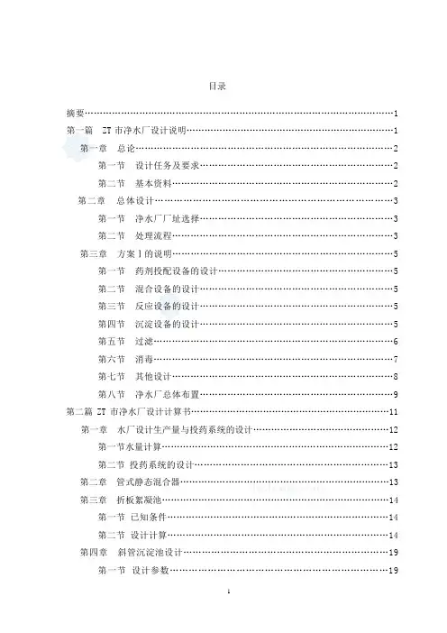
目录摘要 (1)第一篇 ZT市净水厂设计说明 (1)第一章总论 (2)第一节设计任务及要求 (2)第二节基本资料 (2)第二章总体设计 (3)第一节净水厂厂址选择 (3)第二节处理流程 (3)第三章方案Ⅰ的说明 (5)第一节药剂投配设备的设计 (5)第二节混合设备的设计 (5)第三节反应设备的设计 (5)第四节沉淀设备的设计 (5)第五节过滤 (6)第六节消毒 (7)第七节其他设计 (8)第八节净水厂总体布置 (9)第二篇ZT市净水厂设计计算书 (11)第一章水厂设计生产量与投药系统的设计 (12)第一节水量计算 (12)第二节投药系统的设计 (13)第二章管式静态混合器 (13)第三章折板絮凝池 (14)第一节已知条件 (14)第二节设计计算 (14)第四章斜管沉淀池设计 (19)第一节设计参数 (19)第二节设计计算 (19)第五章虹吸滤池设计计算 (22)第六章消毒 (31)第七章清水池 (31)第八章高程布置 (32)第九章Ⅱ号方案的平面尺寸计算 (32)主要参考资料 (33)摘要本设计ZT市污水处理厂的设计、净水厂由两部分组成:污水处理厂设计,净水厂设计。
污水处理厂设计流量为:3.6万m³/d,进水质如下:SS=256mg/L BOD5=262mg/LNH3-N=58.4mg/L TP=3.6mg/L 碱度126 mg/L 出水质要求如下:SS≤30mg/LBODs≤30mg/L NH3-N≤15mg/L TP≤1mg/L NO-3-N≤10mg。
根据进水水质及出水要求,选择了两套方案,方案Ⅰ为A²/O工艺。
由于方案Ⅰ更能有效地脱氮除磷,并且运行较灵活,出水水质好,故选方案Ⅰ为最佳方案。
其工艺流程如下:净水厂设计流量9.4万m³/d,水质为地表水源(见设计任务书)。
根据地表水水质要求,选择两套水处理工艺方案,经过经济技术比较,推荐方案Ⅰ为最佳方案,其工艺流程如下:关键词:污水处理厂;净水厂;氧化沟;A²/O工艺;折板絮凝池;斜管沉淀池;虹吸滤池AbstractThis design is for sewage disposal plant and clarification plant in the city of AL. This design program has been separated two parts: one is for sewage disposal plant, another is for clarification plant. Part Ⅰ:the plant will be able to purify 36000m³/d in scale. The quality of the waste water is as follows:ss=256mg/l,BOD=262mg/l,NH3-N=58。
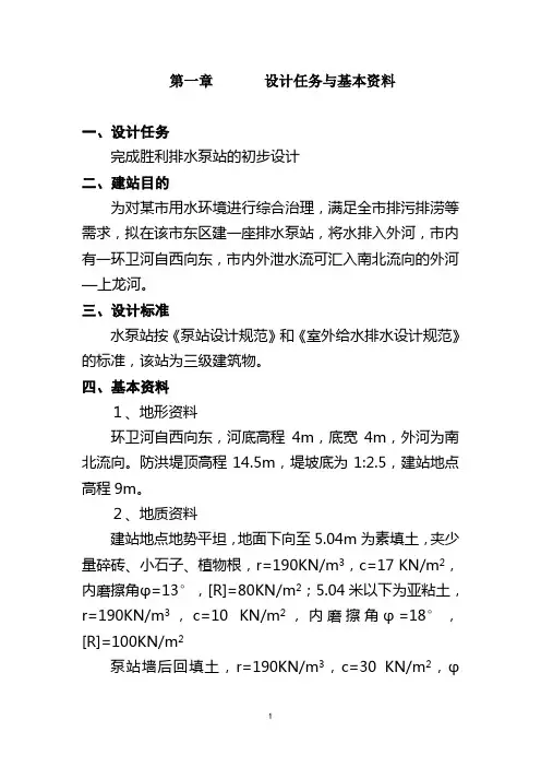
第一章设计任务与基本资料一、设计任务完成胜利排水泵站的初步设计二、建站目的为对某市用水环境进行综合治理,满足全市排污排涝等需求,拟在该市东区建一座排水泵站,将水排入外河,市内有一环卫河自西向东,市内外泄水流可汇入南北流向的外河—上龙河。
三、设计标准水泵站按《泵站设计规范》和《室外给水排水设计规范》的标准,该站为三级建筑物。
四、基本资料1、地形资料环卫河自西向东,河底高程4m,底宽4m,外河为南北流向。
防洪堤顶高程14.5m,堤坡底为1:2.5,建站地点高程9m。
2、地质资料建站地点地势平坦,地面下向至5.04m为素填土,夹少量碎砖、小石子、植物根,r=190KN/m3,c=17 KN/m2,内磨擦角φ=13°,[R]=80KN/m2;5.04米以下为亚粘土,r=190KN/m3,c=10 KN/m2,内磨擦角φ=18°,[R]=100KN/m2泵站墙后回填土,r=190KN/m3,c=30 KN/m2,φ=15°,外磨擦角取(1/3-2/3)φ。
3、水文资料环卫河末底面高程:▽4.0m环卫河河底宽度:4.0m水组位合:4、流量资料:5、交通外河可以行船,附近有公路通往市区,交通便利。
6、电源站址附近有变电所一座,6KV输电线路经过此站。
7、排水时最高气温37°,最高水温25°。
五、其它设计依据1、设计任务与指导书扬州大学20032、《泵站设计规范》GB/T50265-973、《水泵站设计示例与习题》4、《中小型泵站设计与改造技术》储训刘复新主编5、《泵站过流设施与截流闭锁装臵》严登丰著6、《中小型泵站设计图集》第二章泵站设计参数确定一、设计流量确定Q= qA=0.36×11=3.96m3/s式中q为排水率(m3/s/KM2)A为胜利站抽排面积。
二、设计净扬程的确定H=10.5-5=5.5m三、设计扬程初估H设=(1+K)H净=1.2×5.5=6.6m取K=0.2四、确定最大、最小净扬程Hmax=11-5=6mHmin=8.5-5=3.5m第三章水泵选型及设备配套一、水泵机组选型⑴确定泵型方案根据上述扬程计算结果,再加上管路损失,扬程按15%估算,则 H=H+H损=5.5+5.5×15%=6.3m初选泵型:一般情况下,设计扬程小于10米时,宜选用轴流泵;5~20米时,宜选用混流泵。
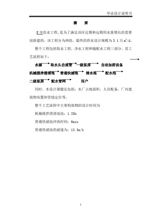
摘要E市给水工程,是为了满足该区近期和远期用水量增长的需要而新建的。
该工程分为两组,最终的供水设计规模为3.1万m3/d,整个工程包括取水工程,净水工程和输配水工程三部分。
其工艺流程如下:水源取水头自流管一级泵房自动加药设备机械搅拌澄清池普通快滤池清水池配水池二级泵房配水管网用户同时,本设计课题还包括:水厂占地面积,人员配备,厂内建筑物布置和管线定位等。
整个工艺流程中主要构筑物的设计时间为机械搅拌澄清池池:1.28h普通快滤池冲洗时间:6min普通快滤池的滤速为:13.3m/h目录第一章概述第一节城市自然条件第二节城市建设规划第三节工程设计第二章设计水量第一节设计用水量第二节设计水量第三章给水水源及取水工程第一节给水水源第二节取水构筑物第三节取水泵站(一级泵站)第四章净水厂第一节机械搅拌澄清池第二节普通快滤池第三节清水池第四节配水池第五节送水泵站(二级泵站)第六节加矾加氯间第五章自动化设计第一节净水厂的自动化设计第六章净水厂总体布置第一节净水厂的流程及平面布置第二节附属建筑第三节净水厂绿化与道路第一章概述第一节城市自然条件一、地下水E市基本无地下水可以开采利用。
二、地表水碧流河贯通E市全境,其水文情况为:历年最大流量为952m3/s,最小流量为8.25m3/s,最高水位66.82m(P=1%),最小水位59.98m(P=97%),平均水位62.84m。
浪高1.1m.碧流河水质符合《生活饮用水水源水质标准》二级标准。
该市有东风水库、万福水库。
其中,离市区最近的无金矿污染的为距离市区30公里,万福水库上游2.5公里。
水库水量充足,水质好。
三、气象该市属亚热带湿润气候,年平均气温18摄氏度,最高气温39摄氏度,最低气温零下9摄氏度,最高月平均气温29.2摄氏度,最低月平均气温5.6摄氏度。
日照时速1850小时,无霜期260天左右,有冰雹、暴雨、干旱等灾害气候影响。
降雨量:多年平均降雨量为1600-2000mm左右,最高降雨量2672.5mm,最小降雨量1432.6mm.境内气候湿润温和,四季分明。
遂宁市安居区石榴坝集中供水站取水泵站工程设计摘要专业:农业水利工程姓名:李定钟指导老师:李乃稳根据设计资料确定出泵站修建的地址,确定取水泵房的规模。
进而通过技术经济综合比较出泵站所选用水泵类型,通过计算确定出泵房以及其附属设施的尺寸,及布置方式,再进行泵房的稳定性验算,根据需要配筋。
首先确定出水泵的流量和扬程,选择合适的泵房类型和水泵类型。
然后进行进出水管、引水建筑物等的详细设计。
对水泵工况点进行校核之后,确定水泵的终选类型。
接着对泵房的辅助设备进行具体布置,确定出水泵的安装高程以及泵房的具体尺寸。
确定出泵房的具体布置以及尺寸之后,就可以对泵房的稳定性进行验算。
达到稳定性要求就可以进行结构计算,算出泵房各结构的钢筋用量以及配筋方式。
最后对泵房的施工组织做出简单的介绍。
关键词:取水泵站、离心泵、供水方案。
AbstactAccording to the design information to determine the address of the pumping station and the size of the pumping prehensive comparison of the pumping station through the technical and economic choose the type of pump, determined the size of the pumping station and its ancillary facilities, and the layout by calculating,then check the stability of the pumping station, calculate the reinforcement configuration.First, determine the pump flow and head, and select the appropriate type of pumping station and pump type. And then proceed to the detailed design of access to water diversion structures. After checking the pump operating point to determine the ultimate choice type of pump. Followed by the specific arrangement of the pumping station auxiliary equipment to determine the elevation of the pump installation and the specific dimensions of the pumping station. Determine the specific layout and size of the pumping station, checking the stability of the pumping station. Achieve the stability requirements can be carried out structural calculations to calculate the pumping station structure steel consumption and reinforcement. Finally, make a simple introduction. about the pumping station construction organization .Key words: water pumping station, centrifugal pumps, water supply scheme.目录1概述 (4)1.1 区域水资源概况 (4)1.2 地质情况 (4)1.3 建筑材料 (4)1.4 对外交通、通讯情况 (5)1.5 组织机构及配套资金落实情况 (5)1.6 群众参与情况 (5)2工程建设条件 (5)2.1 地形地貌 (6)2.2 地质及土壤 (6)2.3 气候 (6)2.4 水文 (6)2.4.1 降水 (7)2.4.2 径流 (7)2.5 水质 (7)2.6 自然植被 (8)2.7 水资源状况 (8)3工程建设的必要性 (9)4站址选择 (9)5用水量预测及设计规模 (10)6方案选择 (12)6.1 泵站基本参数 (12)6.2 离心泵方案 (12)6.3 潜水泵方案 (16)7推荐方案设计 (19)7.1 离心泵泵型选择 (19)7.2泵房类型选择 (19)7.3 泵站进出水管设计 (20)7.4引水建筑物 (21)7.5进水池设计 (21)7.6引渠方案和引水管方案对比 (22)7.6.1引渠方案 (22)7.6.2引水管方案 (26)7.6.3选择引水建筑物方案 (27)7.7 泵房具体布置 (27)7.7.1配电设备布置 (27)7.7.2管路布置 (27)7.7.3泵房辅助设备 (28)7.7.4泵房尺寸设计 (28)7.8 水泵工况点校核 (31)7.9泵房稳定及结构计算 (32)7.9.1抗浮稳定计算 (33)7.9.2 地基承载力校核 (36)7.9.3泵房结构及配筋计算 (37)8施工组织设计 (39)8.1 地基与基础 (39)8.2排水与降低地下水位 (39)8.3基坑开挖 (40)8.4泵房施工 (42)8.5钢管管道施工 (44)9参考文献 (45)1概述1.1 区域水资源概况项目内主要河流有琼江河。
中国矿业大学——环境与测绘学院《水泵及水泵站》课程设计说明书目录1.设计目的及基本资料-----------------------------32.设计流量--------------------------------------43.自流管设计------------------------------------44.水泵设计流量及扬程----------------------------45.水泵机组选择----------------------------------56.吸、压水管的设计------------------------------57.机组及管路布置--------------------------------68.泵站内管路的水力计算--------------------------69.辅助设备的选择和布置--------------------------810.泵站各部分标高的确定--------------------------911.泵房平面尺寸确定------------------------------9设计目的及基本资料设计目的:本课程设计的主要目的是把《水泵及水泵站》、《给水工程》中所获得的理论知识加以系统化。
并应用于设计工作中,使所学知识得到巩固和提高,同时提高同学们有条理地创造性地处理设计资料地独立工作能力。
设计基本资料:1. 某中小水厂,近期设计水量6万米3/日,要求远期10万米3/日(不包括水厂自用水)2. 原水厂水质符合饮用水规定。
根据河岸地质地形以决定采用固定式泵房由吸水井中抽水,吸水井采用自流管从取水头部取水,取水头部采用箱式。
取水头部到吸水井的距离为80米。
3. 水源洪水为标高为48.7米(1%频率);枯水位标高为30.2米(97%频率);常年平均水位标高为39.8米。
4. 净水厂混合井水面标高为58.1米,取水泵房到净水厂管道长900米。
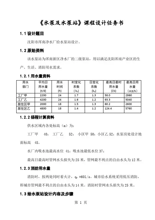
《水泵及水泵站》课程设计任务书1.1设计题目沈阳市浑南净水厂给水泵站设计。
1.2原始资料该水泵站为浑南新区净水厂的二级泵站,用以满足沈阳浑南产业区的生产、生活、消防用水需求。
1.2.1用水量资料1.2.2扬程计算资料供水区域内各处标高(m)为:工厂甲 48;工厂乙 52;小区甲 50;小区乙52;水泵房处设计地面标高 45。
水厂内吸水池最高水位 41;吸水池最低水位37;最高日最高时管网水头损失为25米,管网最不利点的自由水头为12米。
1.2.3消防用水量消防时,按两处同时着火计,q f =60l/s。
城市给水系统采用低压消防,即城市管网最不利点的自由水头为14米。
消防时管网水头损失为25米。
1.3给水泵站设计内容及步骤1.设计流量的确定和设计扬程估算;2.初选水泵和电机;3.机组基础尺寸的确定;4.吸水管路与压水管路计算;5.机组与管道布置;6.吸水管路与压水管路中水头损失的计算;7.水泵安装高度的确定和泵房筒体高度计算;8.附属设备的选择;9.泵房建筑高度的确定;10.泵房平面尺寸的确定。
1.4绘图根据以上设计计算及选出的各种设备进行给水泵房设备布置。
应绘制如下图1.给水泵站平面图。
(1号图纸一张,比例为1:50)。
2.给水泵站剖面图。
(1号图纸一张,比例为1:50)3.绘图要求1)平面图和剖面图上应注明水泵机组位置,管路系统,管件尺寸,位置,各设备之间,设备与建筑维护之间相对位置尺寸及标高,并应附有主要设备明细表。
2)图纸尺寸、标题栏等均应按国家标准绘制。
1.5设计说明书设计完成时应进行设计说明书的整理,说明书应包括下列内容:1.计算部分,列出计算次序、项目、计算公式、符号、单位及结果数据,中间的演算过程从略。
吸压水管路水头损失计算画出线路图。
2.对于选定的水泵型号,泵房土建设计应简要说明确定该方案时的依据及其优点、缺点。
3.本水泵房在设计上的特点。
4.在必要的计算及说明部分,为表达清楚应附有草图。
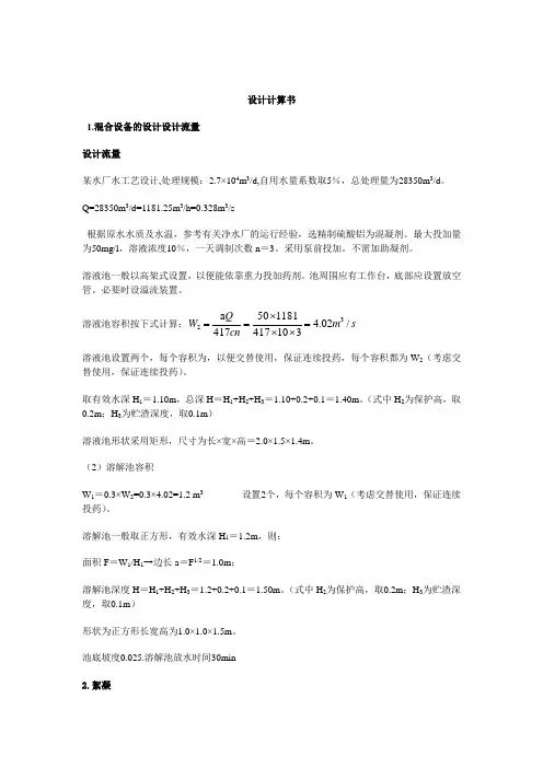
设计计算书1.混合设备的设计设计流量 设计流量某水厂水工艺设计,处理规模:2.7×10⁴m 3/d,自用水量系数取5%,总处理量为28350m 3/d 。
Q=28350m 3/d=1181.25m 3/h=0.328m 3/s根据原水水质及水温,参考有关净水厂的运行经验,选精制硫酸铝为混凝剂。
最大投加量为50mg/l ,溶液浓度10%,一天调制次数n =3。
采用泵前投加。
不需加助凝剂。
溶液池一般以高架式设置,以便能依靠重力投加药剂。
池周围应有工作台,底部应设置放空管。
必要时设溢流装置。
溶液池容积按下式计算:s m cn Q W /02.4310417118150417a 32=⨯⨯⨯==溶液池设置两个,每个容积为,以便交替使用,保证连续投药,每个容积都为W 2(考虑交替使用,保证连续投药)。
取有效水深H 1=1.10m ,总深H =H 1+H 2+H 3=1.10+0.2+0.1=1.40m 。
(式中H 2为保护高,取0.2m ;H 3为贮渣深度,取0.1m )溶液池形状采用矩形,尺寸为长×宽×高=2.0×1.5×1.4m 。
(2)溶解池容积W 1=0.3×W 2=0.3×4.02=1.2 m 3 设置2个,每个容积为W 1(考虑交替使用,保证连续投药)。
溶解池一般取正方形,有效水深H 1=1.2m ,则: 面积F =W 1/H 1→边长a =F 1/2=1.0m ;溶解池深度H =H 1+H 2+H 3=1.2+0.2+0.1=1.50m 。
(式中H 2为保护高,取0.2m ;H 3为贮渣深度,取0.1m )形状为正方形长宽高为1.0×1.0×1.5m 。
池底坡度0.025.溶解池放水时间30min 2.絮凝絮凝池设计(近期)2组,每池设计流量为: Q =0.5m 3/s 。
絮凝时间t =12min ,设计平均水深h =4 m 。
净水厂毕业设计某净水厂毕业设计导读:就爱阅读网友为您分享以下“某净水厂毕业设计”的资讯,希望对您有所帮助,感谢您对92to 的支持!课程设计设计题目:专业班级:姓名:指导教师:山东农业大学水利土木工程学院2006年12月前言自从有了人类的生活和生产活动,人类活动就受制于水的自然循环和社会循环所产生的水量和水质。
城市给水工程的建设是一项系统工程,包括工程的前期立项和环境影响评价、工程的设计与建设资金的筹集。
为了设计好建设好城市给水工程,需要在项目的立项和设计各个环节充分了解工程的内容、要求和设计计算方法,掌握必要的专业知识,使工程建成后达到预期的效果。
为了与理论结合,在课程结束时进行课程设计,可以巩固课堂知识,增加对实际情况的理解。
同时可以涉及新兴工艺,对各个工艺流程进行比较选择。
水处理厂工艺的选择是水处理厂设计最为关键的问题,直接关系到工程建设造价、运行成本何处水水质。
常规水处理工艺(即所谓的混凝、沉淀、过滤、消毒工艺)无论在理论还是在实践上并无重大技术突破。
1.混合工艺其主导工艺仍然是水泵混合、管式静态混合器混合、机械混合和跌水混合等。
2.第1章总论1.1给水处理课程设计任务及要求 1.1.1设计题目某市净水厂设计1.1.2基本资料1、水厂产水量:1组:30000m3/d。
2组:50000 m3/d。
3组:80000 m3/d。
2、水源为河水,原水水质如下:3、厂区地形平坦,地面标高为黄海高程160.0m,水厂占地(1、2组):2.26公顷(155×145m)。
3组:2.4公顷(155×155m) 4、当地气象资料:风向:东北气温(月平均):最高28℃,最低-1.9℃。
5、厂区地下水位高:-5m(水厂相对地面标高为0.00m)。
6、水源取水口位于水厂西北方向50m,水厂位于城市北面2km处。
7、二级泵扬程设为40米。
1.1.3设计内容1、确定水厂的处理工艺流程及净水构筑物、设备的类型和数量。
吉林化工学院毕业设计说明书吉林化工学院毕业设计净水厂送水泵站控制系统设计及应用Design and Application of waterworks water supply pump station control system- I -净水厂送水泵站控制系统设计及应用摘要本课题设计主要设计了一种变频调速恒压供水系统,它主要包括了三个部分既下位机PLC控制部分;上位机WINCC 监控部分;和PLC仿真部分组成的。
它的原理是以西门子S7-300系列作为下位机,由变频器、PLC及PID调节器组成控制系统来调节水泵的输出流量。
电动机泵组由三台水泵并联而成,由变频器或工频电网供电,根据供水系统出口水压和流量来控制变频器电动机泵组之间的切换及速度,使系统运行在最合理的状态,保证按需供水,上位机采用WINCC为监控软件,实时监控系统工作状态。
经调试和仿真运行表明,该系统能够对供水过程进行自动控制,能够有效地降低能耗,保证了供水系统维持在最佳运行状况,提高生产管理水平。
该监控系统安装维护方便,运行稳定可靠,监控软件功能齐全,人机界面友好,使用方便。
关键词:变频调速;恒压供水;PLC;Wincc- II -吉林化工学院毕业设计说明书AbstractThe project design is mainly designed a constant pressure water supply system.It mainly consists of three parts both lower machine PLC control section; PC WINCC monitoring section; and the PLC simulation part. it principle is based on Siemens S7-300 series as the next crew.By the inverter, PLC and PID regulator integral control system to adjust the pump output flow.Motor pump group of three pumps parallel and become, by inverter or industrial frequency power supply, according to the water supply system to control the pressure and flow export of frequency switching between motor pump group, so the system and speed in the most reasonable position, make sure on-demand water supply. In this paper, wincc as PC monitoring software. Commissioning and operation shows that the system can be automatic control of water supply process can effectively reduce the energy consumption and ensure the water supply system to maintain in the best operation condition, improve production management level. Monitoring systems easy installation and maintenance, operation is stable, reliable; Monitoring software function is well-found, friendly man-machine interface, easy to use.Key Words:Variable frequency speed-regulating;Constant-pressure watersupply;Plc;Wincc- III -净水厂送水泵站控制系统设计及应用目录摘要 (II)Abstract (III)第1章绪论 (1)1.1 课题研究背景及意义 (1)1.2 变频调速恒压供水的发展 (1)1.3 变频恒压供水系统的国内外研究现状 (1)1.4 本文主要研究内容 (2)第2章恒压供水基本原理 (3)2.1 恒压供水工艺简介 (3)2.2 变频调速供水原理 (3)2.3 变频恒压供水系统的节能原理 (5)2.4 变频恒压供水系统的组成及原理图 (5)第3章变频调速恒压供水控制系统设计 (8)3.1 变频恒压供水系统控制原理 (8)3.2 恒压供水系统方案设计与选择 (8)3.3 系统工作原理 (9)3.3.1 系统控制组成 (9)3.3.2 系统工作原理 (10)3.3.3 PID调节恒压控制原理 (11)3.4 硬件选择 (11)3.4.1 PLC及模块 (12)3.4.2 变频器 (12)3.4.3 水泵机组 (13)3.4.4 液位变送器 (13)3.4.5 压力变送器 (13)3.5 电气设备选型 (14)3.5.1 用电设备负荷计算 (14)3.5.2 用电设备尖峰电流的计算 (14)3.5.3 熔断器选择与校验 (15)3.5.4 低压断路器选择与校验 (16)3.6.5 低压隔离开关选择 (16)- IV -吉林化工学院毕业设计说明书第4章程序设计 (18)4.1 系统主电路设计 (18)4.2 系统控制电路分析及其设计 (19)4.3 PLC I/O分配 (21)4.4 PLC程序设计 (21)第5章监控程序设计 (25)5.1 WinCC软件简介 (25)5.2 恒压供水系统监控界面 (25)5.2.1 恒压供水系统登录画面 (25)5.2.2 恒压供水系统主画面 (26)5.2.3 恒压供水系统PID画面 (27)5.2.4 恒压供水系统报警画面 (27)5.2.5 恒压供水系统历史曲线画面 (28)结束语 (29)参考文献 (30)致谢 (31)- V -吉林化工学院毕业设计说明书第1章绪论1.1 课题研究背景及意义水是生命之源,是人类赖以生存和发展的不可替代的重要资源之一。
学本科生毕业设计说明书(毕业论文)题目:村镇供水厂电气及仪表控制系统设计学生姓名:学号: 1专业:自动化班级:自动化2班指导教师:村镇供水厂电气及仪表控制系统设计摘要根据村镇的供水的要求,设计了一套电气及仪表控制的变频恒压供水系统。
变频恒压供水控制系统由变频器、压力传感器、水泵机组、数字显示仪表等组成。
供水厂为远在方圆15Km外的几十个村庄供水,供水厂由加压站和水源井群组成,水源井群由3眼井组成。
先把水源井中的水注入加压站的蓄水池中,然后由加压泵从蓄水池通过变频调速控制为用户供水。
蓄水池包含三台潜水泵电机控制水位,依据水位的不同,启动不同台数的潜水泵,功率大一台的应采用降压启动。
同时包含三台加压水泵电机,它们组成变频循环运行系统,控制柜应能根据用户需求的供水压力供水,采用变频器实现对加压水泵的软启动和变频调速,实现任意一台水泵的的变、工频切换及两台水泵之间的自动启动与停止,压力传感器检测当前水压信号,送入变频器与设定值比较,进行PID运算,从而控制变频器的输出电压和频率,进而改变水泵的转速来改变供水量,最终保持管网压力稳定在设定值附近,实现恒压供水。
关键词:恒压供水;变频器;PID控制;变频调速;仪表Rural Water Supply Plant Electrical and Instrumentation ControlSystem DesignAbstractAccording to the requirement of the rural water supply, Design a set of electrical and instrument control of frequency conversion constant pressure water supply system. Frequency conversion constant pressure water supply control system by frequency converter, pressure sensor, pumping unit, Digital display instrument, etc. Water supply plant for dozens of villages in fangyuan 15 km outside the water supply, Water supply plant is composed of pressure and water well group, Source well group consists of three Wells. Put water Wells water injection pressure in the reservoir, Then the pump water from the reservoir through the frequency control of motor speed control for users.Reservoir contains three submersible pump motor control water level, According to the water level is different, Start the different sets of submersible pump, Power of freshman should adopt step-down startup. At the same time contains three pressurized water pump motor, They are composed of variable frequency cycle operation system, control cabinet should be able to supply pressure water supply according to user requirements, Frequency converter, is adopted to realize of pressurized water pump soft start and frequency control of motor speed, Implement as a pump of variable, power frequency switching and automatic start and stop, between the two pumps, Current hydraulic pressure sensor signal, Into the inverter compared with the set value to PID arithmetic, To control the output voltage and frequency of the inverter, Can make a big difference to the speed of water pump motor to change water supply, Eventually maintain stability of the pipe network pressure near the set point, To realize constant pressure water supply.Key words: constant pressure water supply; frequency converter; PID controlling; variable frequency speed regulation; instrument目录摘要 (I)Abstract (II)第一章绪论 (1)1.1 变频技术研究背景及意义 (1)1.1.1 变频技术的研究背景 (1)1.1.2 变频恒压供水技术的重大研究意义 (1)1.2 变频恒压供水国内外研究现状 (2)1.3 仪器仪表 (2)1.3.1 仪表在控制系统中的作用 (3)1.3.2 给排水的常用仪表及其作用 (3)1.4 本设计的主要研究内容 (4)第二章控制方案拟定 (6)2.1 变频调速恒压供水的主要特点 (6)2.2 变频调速恒压供水的节能原理 (7)2.3 常见供水系统的安全性问题 (8)2.3.1 对供水的电机和电网进行的保护 (8)2.3.2 水锤效应的产生原因及其消除方法 (9)2.3.3 延长水泵寿命的因素 (9)2.4 研究对象 (10)2.5 供水厂供水的构成 (10)2.5.1 水源井群给水池供水部分 (10)2.5.2 控制方案的确定 (11)第三章系统的硬件设计 (13)3.1 系统的理论分析 (13)3.2 PID参数的整定 (14)3.2.1 PID及其发展史的介绍 (14)3.2.2 PID控制器的参数整定 (17)3.2.3 PID参数整定的相关原则 (17)3.3 补水部分的设计 (21)3.3.1 硬件电路图 (21)3.3.2 补水部分的工作原理 (23)3.4 供水部分的设计 (25)3.4.1 硬件电路图 (25)3.4.2 供水部分的工作原理 (27)第四章系统主要设备的选型及介绍 (29)4.1 变频器 (29)4.1.1 变频器型号的选择及外形、尺寸 (29)4.1.2 变频器的接线方式 (30)4.1.3 变频器内部参数的设置 (30)4.1.4 变频器的工作原理 (33)4.2 仪表的选择 (34)4.2.1 液位传感器的选择 (34)4.2.2 压力变送器的选择 (36)4.2.3 电压表的选择 (37)4.3 其他电器的选择 (37)4.3.1 变压器的选择 (37)4.3.2 自耦变压器的选择 (38)4.3.3 隔离开关的选择 (38)4.3.4 空气开关的选择 (39)4.3.5 万能转换开关的选择 (39)4.3.6 热继电器的选择 (40)4.3.7 接触器的选择 (40)4.3.8 时间继电器的选择 (41)4.3.9 中间继电器的选择 (41)4.3.10 电位器的选择 (42)4.3.11 启动按钮和停止按钮的选择 (42)4.3.12 指示灯的选择 (43)4.4 电线及电缆的选择 (43)第五章结束语 (45)参考文献 (46)附录 (48)附录1:电器的选型表 (48)附录2:仪表的接线端子 (50)附录3:补水部分硬件电路图 (51)附录4 供水部分硬件电路图 (52)感谢 (53)第一章绪论1.1变频技术研究背景及意义1.1.1变频技术的研究背景随着电力电子技术的快速发展,变频器的功能也越来越强大。
土木学院课程设计任务书设计名称水泵及水泵站专业____ 给水排水工程_____ 年级班别 08给排水学号_ 20081267__ ___ 学生姓名孙斐 ____ 指导教师_______ 张莹_____ ____2010 年 6 月20 日《水泵及水泵站》课程设计任务书一、设计任务(一)设计目的(1)使学生所获得的专业理论知识加以系统化,整体化,以便于巩固和扩大所学的专业知识;(2)培养学生独立分析,解决实际问题的能力;(3)提高设计计算技巧和编写说明书及绘图能力;(4)为适应工作需要打一下的基础。
培养学生具有一定的泵站设计能力同过课程设计,使学生进一步将所学的基础理论、基础技能综合的运用与设计实践,熟悉设计方法和步骤。
(二)设计要求1、要求每个学生独立完成设计任务,自己确定设计方案。
2、要正确的运用设计资料。
3、设计要结合工程实际,全面考虑,尽量的使自己的设计具有实际施工价值。
(三)设计题目题目:某泵站课程设计,主要设计内容如下1、资料部分1)近期设计水量10万米3/日,要求远期15万米3/日(不包括水厂自用水)2)原水厂水质符合饮用水规定。
河边无冰冻现象,根据河岸地质地形以决定采用固定式泵房由吸水井中抽水,吸水井采用自流管从取水头部取水,取水头部采用箱式。
取水头部到吸水井的距离为100米。
3) 水源洪水为标高为73.1米(1%频率);枯水位标高为65.5米(97%频率);常年平均水位标高为68.2米。
4) 净水厂混合井水面标高为100.20米,取水泵房到净水厂管道长1000米。
5) 地区气候资料可根据设计需要由当地气象部门提供。
6)水厂为双电源进行。
2、设计部分1)确定泵站设计流量、设计扬程;2)初步确定水泵、电机的型号,工作备用泵的台数3) 进行水泵机组和吸、压水管路的计算与布置4)计算泵站范围内吸、压水管路的水头损失,进行泵站工作的精确计算5) 泵站各部分尺寸的确定6)泵房选择、泵房平面和高程布置3、图纸部分1)泵站平面布置图(包括主要设备机组位置,吸、压水管路位置及其它附属设备机组的位置),比例尺1:1002)泵站立面布置图(包括主要设备机组高度,吸、压水管路高度及其它附属设备机组的高度),比例尺1:1003)泵站剖面图4、撰写泵站设计计算/说明书包括确定水泵、电机的型号,工作备用泵的台数;水泵机组和吸、压水管路的计算与布置;吸、压水管路的水头损失以及泵站工作的精确计算等二、设计成果要求1.设计说明书一份(包括计算),要求书面整洁、文理通顺、论证合理、层次分明、计算无误。
本科生毕业设计说明书(毕业论文)题目:电厂综合水泵房水泵变频调速控制系统设计电厂综合水泵房水泵变频调速控制系统设计摘要本论文是根据某电厂综合水泵房工艺要求,现拟对中水提升泵和工业补给水泵两套系统进行变频调速改造。
其中中水提升泵系统(一控三),其变频柜控制三台75KW水泵,变频泵定时循环运行,一周自动切换一次,当变频泵不能满足要求时,自动软启动一台工频泵,当变频泵仍然不能满足压力给定值时,再自动软启动第三台水泵。
工业补给水泵系统(一控二),其变频柜只控制两台37KW小泵,水泵不要求定时循环运行,但能够手动切换运行。
当变频泵不能满足要求时,自动启动另一台工频小泵。
75KW大泵只能工频手动控制,不参与变频自动控制。
两套系统的基本构成均由变频器(含PID)、软启动器、电动机、压力传感器等构成,而且都利用了变频器来控制水泵电机的软启动和转速。
压力变送器用来检测水泵房管网中的当前水压,以电信号的方式送入变频器的PID控制器与设定值进行比较后执行PID运算,对变频器的输出频率和电压进行控制,从而改变水泵电机的转速进而改变供水量,最终使管网中的水压稳定在设定值的附近。
关键词:变频器、软启动器、水泵、PID、调速The Design of Frequency Control System of an Integrated WaterPump House of a Power PlantAbstractThis paper is based on technical requirements of an integrated water pump house of a power plant. It is intended for water lift pump and industrial water supply pump frequency control two systems transformation.Where the water lift pump system (one control three), its variable frequency counter control three pumps of 75KW, these pumps need timing loop operation, one week automatically switch once. When one pump can not meet the requirements, automatically starts frequency pump, when two pump still can not meet the pressure setpoint, and then a third pump automatic soft starts.Industrial supply pump system (one control two), its variable frequency counter only control two small pumps of 37KW, the two pumps do not require timing loop to run, but the system can be run manually, when one pump can not meet the requirements, automatically starts another small pump. 75KW large pump only manual control by power frequency and it does not participate in frequency control.The basic structure of the two systems by the frequency inverter (including PID), soft starter, motor, pressure sensors, etc. and both two systems have taken advantage of the inverter to control the pump motor soft start and speed. Pressure transmitter used to detect current pipe pressure of pump, in the form of electrical signals sented into the PID controller of inverter and compared with the set value , after that the PID operation is performed, which is to control the inverter output frequency and voltage, thus changing the pump motor speed and then change the water supply, and finally making the pipe network water pressure stabilized at the setpoint nearby.Keywords: frequency inverter, soft starter, water pump, PID, speed control目录摘要 (I)Abstract ........................................................................................................................................................... I I 第一章引言 .. (1)1.1 研究背景 (1)1.1.1 变频技术的国内外发展与现状 (1)1.1.2 国内外水泵变频系统的现状 (1)1.2 本设计研究的主要内容 (2)第二章水泵变频调速控制系统总体设计方案 (5)2.1变频调速控制系统的理论基础 (5)2.1.1三相异步电动机的调速原理 (5)2.1.2软启动器及其使用 (6)2.2水泵变频调速控制系统的分析说明 (9)2.2.1水泵变频调速恒压供水系统构成 (10)2.2.2水泵变频调速恒压供水系统的控制策略 (10)2.2.3两系统的主电路接线图 (11)2.2.4软启动器控制系统的过程分析 (13)第三章系统硬件的设计 (17)3.1变频控制柜的组成 (17)3.2 变频器 (18)3.2.1变频器的构成 (18)3.2.2变频器的主电路 (18)3.2.3变频器的控制电路 (19)3.2.4变频器的特点与比较 (21)3.2.5变频器的选型 (22)3.2.6变频器的外部运行操作 (23)3.3 PID调节器 (24)3.4软启动器的选择 (25)3.5压力变送器的选择 (26)3.6其它电气元件 (27)第四章MM430系列变频器的快速调试 (32)4.1参数复位 (32)4.2快速调试 (33)4.3功能调试 (34)总结 (35)参考文献 (36)附录A (37)致谢 (41)第一章引言1.1 研究背景1.1.1 变频技术的国内外发展与现状近年来电力电子器件的材料开发和制造工艺水平不断提高,尤其是高压大容量绝缘栅双极型晶体管IGBT、集成门极换向晶闸管IGCT器件的成功开发,与此同时伴随着微型计算机控制技术及电机拖动控制系统理论的发展,使大功率变频技术得以迅速发展,性能日臻完善。
净水厂给水泵站课程设计一、教学目标本节课的教学目标是让学生掌握净水厂给水泵站的基本原理、结构和运行方式,了解给水泵站在净水厂中的重要作用,提高学生对给水泵站运行和管理的认识。
1.了解给水泵站的基本原理和结构。
2.掌握给水泵站的运行方式和调节方法。
3.熟知给水泵站在净水厂中的作用。
4.能够分析给水泵站运行中的问题,并提出解决方案。
5.能够对给水泵站进行简单的维护和保养。
6.能够运用所学知识对给水泵站进行优化运行和管理。
情感态度价值观目标:1.培养学生对给水泵站运行和管理的兴趣,提高学生的专业素养。
2.培养学生热爱祖国、服务人民的精神风貌。
3.培养学生团队协作、勇于创新的职业品质。
二、教学内容本节课的教学内容主要包括给水泵站的基本原理、结构、运行方式以及在净水厂中的作用。
1.给水泵站的基本原理:讲解给水泵站的工作原理,让学生了解水泵的工作原理及其在给水泵站中的应用。
2.给水泵站的结构:介绍给水泵站的主要组成部分,如水泵、电机、传动装置、控制系统等,并讲解各部分的功能和作用。
3.给水泵站的运行方式:讲解给水泵站的运行方式及其调节方法,让学生了解给水泵站如何实现高效运行。
4.给水泵站在净水厂中的作用:阐述给水泵站在净水厂中的重要性,让学生了解给水泵站在净水工艺中的地位。
三、教学方法为了提高学生的学习兴趣和主动性,本节课采用多种教学方法相结合的方式。
1.讲授法:讲解给水泵站的基本原理、结构和运行方式,让学生掌握给水泵站的相关知识。
2.案例分析法:分析给水泵站运行中的实际案例,让学生学会分析问题并提出解决方案。
3.实验法:学生参观净水厂给水泵站,让学生直观地了解给水泵站的运行情况和实际应用。
4.讨论法:学生分组讨论,培养学生的团队协作能力和创新思维。
四、教学资源为了支持教学内容和教学方法的实施,本节课准备以下教学资源:1.教材:选用符合课程标准的教材,为学生提供系统、科学的学习资料。
2.参考书:提供相关领域的参考书籍,拓展学生的知识视野。
10v - 1- h 局部 - (H SS + L )i v - 1- h 局部 - h 水平括从吸水喇叭口至真空表安装处的所有水头损失(沿程与局部)。
v 122g可以根据最大抽水量和真空表处的过水断面积来计算。
其中吸水管中局部水头损失h S 1 局部应按水力公式计算,其中局部阻力系数由设计手册查得。
这时由于立管长度未定(见下图 1),沿程水头损失未知,但水平的长度 L 已知,可近似地令:L =10m (认为 H SS =X )。
L真空表HssX图 1 吸水管示意图H SS = H S ' 22gH SS =H S ' 22g1 + i计算结果如下:表 6-1 局部水头损失计算表局部水头损失计算表——350S44管件 管径(mm) 局部阻力系 最大抽水量 数ε (m³/h) 最大流速(m/s) v1^2/2gh=εX(v^2/2g)喇叭口 750 0.1 1116 0.70 0.025 0.0025 钢制焊接 90°弯头 5000.9611161.580.1270.1219伸缩接头 5000.2111161.580.1270.0267c a b a b a c泵BL机器间图2机器间平面布置示意图第八章二泵站吸水井8.1吸水井的高程计算吸水井最低水位为16m,最高水位为18m,地面标高为19m,地下水位为16.5m,考虑到本次设计吸水管不设阀门,泵轴线应高于或等于吸水井最高水位,这里取泵轴线标高18.00m,则实际安装高度H SS‘应小于或等于2m,给予安全考虑,取H SS=2m,但根据上述计算结果,350S44型泵的H SS=2.44m,吸水井淹没深度应小于或等于0.44m,吸水喇叭口高0.53m,距井底0.6m,则吸水井总高度19-16+0.44+0.53+0.6=4.57m。
则对于300S58A型泵,吸水井淹没深度为0.5m,吸水喇叭口高取0.53m,距井底0.54m。
Design of Intelligent Control System for Greenhouse Water Pump Basedon Internet of ThingsDingzhu XueJiLinAgriculturalUniversity,ChangChun,130118,China;**************Keywords: Internet of things; Automatic control; Water PumpA bstract. With the popularity of networking technology, agriculture will gradually shift from a manpower centered, depending on the isolated machinery production mode to the information and software centric mode of production, therefore a variety of automatic and intelligent remote control equipment is used extensively. The temperature sensor, humidity sensor, PH sensor, photometric sensor and CO2 sensor which use the International System in an intelligent water pump control system for a greenhouse can detect the physics parameters of temperature, relative humidity, PH value, strength of illumination net, soil nutrient and CO2 concentration. By displaying in real-time through a variety of instruments, or as a factor of an auto control pump system used in the automatic control of water pump, the system can ensure a good environment for crops. This system is mainly composed of MCU module for data transmission to control the running state of water pump. Moreover, the system equipped with a remote control device can realize manual remote control. Even manually controlling the water pump can improve the reliability and safety of the pump system in other emergency situations.IntroductionAt present, modern greenhouses management has gradually tended to be more intelligent and automatic, so how to improve labor efficiency become the main problem people focus on. The traditional manual control cannot meet the requirement of people 【1】. In addition, people’s struggling between the pump and the switch back and forth cost much of the time and laborites. So a remote control device is badly in need of to solve this problem. At the same time, with the development of intelligent control technology, the construction of automatic and intelligent greenhouses system becomes possible 【2-5】. The pump automatic control system with single chip microcomputer interface introduced in this paper can be very convenient to coordinate the rest of the single chip microcomputer system sensor detection equipment to complete the control of the indoor temperature and humidity in the greenhouse.System StructureThe irrigation remote control system consists of a single chip microprocessor (data processing, analysis center) and remote control device. The manual operation of the pump can be realized by remote control device, and the automatic operation of the pump can be made by the instruction from the data processing center of the single chip. The operating principle diagram of the automatic pump control system is shown in figure 1.(1)The design of the system hardware adopts the current popular modular. Hardware system consists of three functional modules, that is, reception, lack of soil environmental temperature and humidity detection module, the water level detection module, single-chip microcomputer control module. The overall system employs custom communication protocols. Considering the characteristics of agricultural application, the control equipment is self-developed not using expensive programmable controller (PLC) and ready-made wireless modem (radio modem) and so on. Therefore, this equipment with the lowest cost in the domestic similar system effectively reduces the cost of the system. Furthermore, it’s more convenient for agricultural extension and application 【6】.7th International Conference on Education, Management, Information and Computer Science (ICEMC 2017)Figure1 The Working Principle of Automatic Pump Control System(2) Wireless transmission scheme uses PT2262 / PT2272 coding decoding circuit, 315 MHZ transmitting frequency and 8 km Maximum control radius, 531441 address code is available in switch, which can effectively avoid Interference frequency and interference signal. Wireless receiving head adopts 315 MHZ super heterodyne to receive a receiving circuit formed by℃℃MICRF211 chip. The temperature range is from -30 to 85, which can be adapted to the high temperature environment of greenhouse【7】.(3) A large current mutation will be formed when the Irrigation water pump is operated, so electromagnetic interference is very serious. If certain technical measures cannot be adopted, the system cannot work properly. Staggered water pump switch, data sampling, data transmission time, setting the watchdog circuit, photoelectric isolation, increasing the bus drive capacity and other hardware measures can ensure the stability of the system【7-8】.(4) There is pump phase protection circuit in the design of the system. Once the circuit becomes abnormal, the pump can be stopped automatically. Thus the normal operation of the pump can be ensured and the service life can be extended which make the circuit work smoothly【9】.(5) The system controls the best environmental parameters of crop growth in different periods through single chip microcomputer to realize the intelligent management of the greenhouse【10】. It’s characterized with easy operation, high automatization and good human-computer interaction, which can improve the quality and efficiency of production. Data processing center controls the running status of the pump in real time data communication. So the temperature and humidity for the greenhouses can be controlled in the scientific and ideal environment suitable for the growth of the plants.The Design of Hard WareThe hardware is composed of manual remote control and MCU with sensor intelligent control system. The real-time monitoring network of greenhouse centers on single-chip microprocessor. Other components such as soil temperature and humidity sensors, air temperature and humidity sensor, liquid level sensor, wireless transceiver module, liquid crystal display module work together.The classic design of the current circuit is used in most of the system. The remote control circuit, a low power and low cost universal coding and decoding circuit composed of PT2262/2272 transceiver circuit is made by CMOS technology produced by PuCheng company in TaiWan.In this system, 315M / 433M super heterodyne receiver head module is selected for the remote transmission of the signal. The receiver sensitivity can reach -114dBm, operating frequency is 315MHz and 433.92MHz. Power supply voltage input range can be widely selected, any value of the voltage between 3V and 5.5V can be chosen and the power consumption (5.0V/9.6 mA) is low. The continuous data rate of receiving encoded is up to 2.4 KBPS (Manchester code). This module is featured with good selectivity and spurious radiation suppression ability. [14]The temperature range is from -30 to 85which can meet the requirement of the high temperature environmen ℃℃t of greenhouse.Microprocessor is a central part of the whole system and single chip is the core of microprocessor. Microcontroller external crystals and reset circuit, is mainly used for soil temperature and humidity sensor, the water pressure sensor data analysis process and the relay control, water pump, such as functional modules. Temperature and humidity sensor DHT11 contains already calibrated digital composite signal output of the temperature and humidity sensor. The measurement range of relative humidity is 20% ~ 90%RH and celsius temperature is 0 ~ 50. ℃AT35-3 type liquid level sensor produced by Bi He Company in Shenzhen is chosen as pressure type water level sensor. It can be used to measure the opening level of containers and canals, lakes and Wells. It has the characteristics of simple structure, accurate measurement and convenient installation.Three Lack of Phase Protection of the Water Pump. This design focuses on the lack of phase protection of the pump. When the motor is running, the power missing, the motor still rotating, but it is obvious in low speed. If heating up sharply, the motor may be burned. If the motor is in the state of stopping, once started in the state of lack of phase, the motor buzzing, not turning up. If not cutting off the power for a long time, the motor will be burned. If it is burned because of lack of phase, the motor will be found two sets of winding are black. It indicates that the breakdown, inter-turn short circuit, or phase short circuit occurs. The performance of the protectors must have wide capacity and wide range of applications, so to achieve a wide range of linear current sampling is one of the key technologies of the system. It is difficult for commercial current transformer to achieve wide range linear current sampling due to magnetic saturation. So this paper uses a self-made current transformer to overcome the magnetic saturation, in order to achieve a wide range of current linear sampling.Figure 2 Lack of a protection circuit Schematic diagram The circuit Schematic diagram of the device is shown in figure 2. J1, J2 and J3 are three inductance coils which are respectively sheathed in the three-phase electric current, which make up the induction electromotive force ring. When the three-phase power lines are in good condition, not producing self-inductance electromotive force, then the circuit will maintain the original state-not working. When there is no current in one of the three phases or when the current fluctuation is large, it will induce the electromotive force in two of the induction coils J1, J2, J3, rectify the diode, charge the capacitor C1, and add the voltage to the transistor Q4- Q6 transistor conduction. At this time the voltage clutter signal through the resistor R10 is added to the 555 timer trigger side, 3 feet will output a high level so Q3 is conducted, and the relay jump off the main circuit power supply, which can play a role of protecting motor. When the voltage of the 6 pin is <2/3VCC, the voltage of the 3 foot is turned from high level to low level, the Q3 cut-off relay is not working, and the maincircuit is normally operated. The motor M is protected. 12V DC power supply is set in the circuit to make the circuit work smoothly.The Software System DesignThe software is written in C language and microprocessor editor Keil software and adopts modular programming method at the meantime. The program flow diagram is shown in Figure 3. Each part is written separately. Then these parts are connected to the Display function. When the water pump control system works, the main function is used to control the various parts of the Display function.Figure 3 Software flow chartSummaryIn this paper, the remote management system is designed based on the Internet of things technology. It is characterized by low cost, easy to use and high reliability, which can achieve a number of greenhouses water supply. The new design of the water pump power failure protection basically solves the problem that the motor is still rotating when the power supply is out of phase, causing the motor to rise rapidly and burn the motor.AcknowledgmentsFunds for the research was provided by scientific research fund of Jilin Agricultural University(No.201620),Jilin province university undergraduate science and technology innovation fund-portable soil comprehensive indicator tester; spark plan Ministry of science and technology (2015GA660004).References[1]Ke Xiaogan. Water level acquisition and remote transmission system research [D]. NanjingUniversity of Hehai, master's degree thesis, 2013.36-45.[2]Liu Jingzhi. Foreign mechanical and electrical development of the cause of irrigation anddrainage [J]. Netease water conservancy, 2016, 8, 26.[3]Chen Peiguo. DW15 series universal circuit breaker update and improvement [J]. ElectricWorld, 2005, 8.[4]Gu Yi, He Xing, Zhang Weidong. Remote monitoring of unattended pumping stations in urbanareas [J]. China Water Supply and Drainage, 2014, 20 (9): 84-86.[5]Guiyun Tian. Principle and Application of Single Chip Microcomputer [M]. Beijing: HigherEducation Press, 50 ~ 90.[6]Wang Xiaoming. Motor single-chip control [J]. Academic Journal, 2012,13 (15): 1322-1755.[7]Huang Xianwu. Sensor principle and application [M] 1st edition, Chengdu, University ofElectronic Science and Technology Press, 2005.[8]Liang Ruilin. Sensor application circuit and the actual production [M] Technology Press, 2013.[9]Bi Manqing. Electronic technology experiment and curriculum design [M]. 1st edition. Beijing:Machinery Industry Press, 2011: 163 ~ 165.[10]Ma Zhongmei, Jie Shunxin, Zhang Kai, etc. C language application programming[M]. FourthEdition. Beijing: Beijing University of Aeronautics and Astronautics Press, 2007: 41 ~ 42.。