派克液压过滤器产品介绍概述.
- 格式:ppt
- 大小:5.43 MB
- 文档页数:36
派克比例阀参数-概述说明以及解释1.引言1.1 概述概述部分:派克比例阀是一种常用的工业控制阀,用于调节液体或气体流量。
其特点是通过改变阀门的开度来控制介质的流量,以达到精确控制的目的。
派克比例阀广泛应用于自动化控制系统中,特别是在需要准确控制流量的场合,如工厂生产线、机械加工、化工以及液压系统等领域。
派克比例阀的参数是指影响其性能和控制精度的各项指标。
常见的派克比例阀参数包括响应时间、线性度、灵敏度、控制精度等。
响应时间是指控制信号作用到阀门上所需的时间,通常以毫秒为单位。
线性度是指阀门在不同开度下流量的变化关系,通常以百分比表示,线性度越好,阀门的流量控制越精确。
灵敏度是指阀门对控制信号的响应程度,灵敏度越高,阀门的调节范围越大。
控制精度是指阀门输出流量与期望流量之间的误差,通常以百分比表示,控制精度越高,阀门的流量控制越准确。
了解派克比例阀的参数对于正确选择和使用该阀门至关重要。
根据实际需求,我们可以根据阀门参数来判断适合的使用场景和控制要求,从而保证流体系统的稳定运行和可靠性。
在接下来的文章中,我们将重点介绍派克比例阀的各项参数,并探讨其对流体控制的影响,帮助读者深入理解和应用派克比例阀。
1.2 文章结构文章结构部分的内容如下:文章结构是指整篇文章的组织方式和内容的排列顺序。
一个良好的文章结构可以使读者更容易理解和把握文章的主题和要点。
本文将按照以下结构来组织内容:引言部分(Introduction):该部分主要对派克比例阀参数进行概述,介绍派克比例阀的基本概念及其在实际应用中的重要性。
同时还会介绍文章的结构和目的,让读者对全文有一个整体的了解。
正文部分(Body):正文部分是整篇文章的核心部分,将详细介绍派克比例阀参数的相关内容。
其中,第一个要点将重点介绍派克比例阀的工作原理、结构特点以及参数的定义和计算方法;第二个要点将深入讨论派克比例阀参数在实际应用中的影响因素和调节方法。
结论部分(Conclusion):结论部分将对正文部分的内容进行总结,并提炼出文章的主要观点和结论。
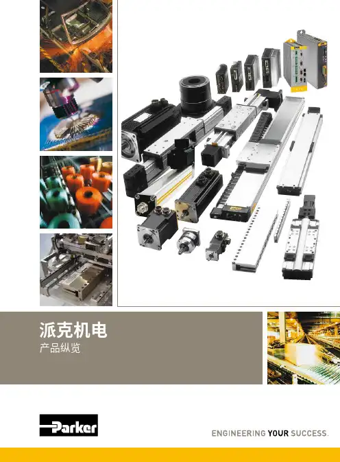
■ᅠ高技术应用的控制器■ᅠ基于工业以太网的运动控制系统■ᅠ集成多轴运动控制器■ᅠ智能伺服驱动器■ᅠ工业以太网多轴伺服驱动器■ᅠ通用伺服驱动器■ᅠ智能直流调速器■ᅠ通用直流调速器派克机电产品纵览运动控制驱动技术直流调速器■ᅠ智能交流变频器■ᅠ通用交流变频器交流变频器2■ᅠ滚珠丝杠驱动工作台■ᅠ直线电机驱动工作台■ᅠ高精度微型工作台■ᅠ经济型■ᅠ高精度高精度执行器与工作台行星齿轮减速机■ᅠ伺服电机■ᅠ防爆伺服电机■ᅠ高速大功率伺服电机■ᅠ高性能车载电机■ᅠ直线电机组件■ᅠ直驱电机■ᅠ高性能伺服电机■ᅠ电动缸■ᅠ线性执行器电机执行器3ACR 系列是派克主要的独立封装的运动控制器,能够实现多达八轴的运动控制。
简单易用的项目开发组件,使应用系统构建及维护快速,高效。
ACR74C/78C 是4轴/8轴运动控制器;ACR74T 是集成4轴步进电机驱动器的驱控一体机;ACR74V/78V 是集成4轴/8轴低压伺服驱动器的驱控一体机。
强大、集成化和为机械市场设计的派克自动化运动控制器(PAC)为OEM 提供了基于标准的自动化解决方案,能够满足严苛的应用要求。
PAC 将先进逻辑、多轴运动、信号处理和网络发布的可视化整合到一个以性能为导向的解决方案中,进而消除不必要的硬件和通信链接,并提高开发者的效率。
PAC网络架构派克自动化运动控制器 - PACACR 控制器系列•ᅠ K eywords: PAC CPU 运算能力更强•ᅠP AC: EtherCAT, 多轴插补•ᅠA CR:模拟量模式,简单易用ACR7C/7V ACR7000PAC3404智能伺服驱动器 - Compax3Compax3是派克汉尼汾不同国家和地区推出的伺服驱动器产品。
驱动器系列包括单轴,多轴驱动器,还有液压控制器。
这一系列驱动的功率从1到110kVA。
这一伺服驱动器的整个研发及制造过程全部在德国完成。
另外的生产基地也在美国建成。
作为一款销往不同国家和地区的伺服驱动控制器,Compax3在世界各地都有销售。
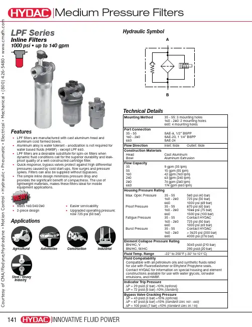
Hydraulic SymbolApplicationsAgricultural Automotive Construction IndustrialSteel / HeavyIndustryABFeaturesUÊ L PF filters are manufactured with cast aluminum head and aluminum cold formed bowls.UÊ A luminum alloy is water tolerant - anodization is not required for water based fluids (HWBF) - except LPF 660.UÊ L PF filters are a desirable substitute for spin-on filters when dynamic fluid conditions call for the superior durability and leak-proof quality of a well-constructed cartridge filter.UÊ Q uick-response, bypass valves protect against high differential pressures caused by cold start-ups, flow surges and pressure spikes. Filters can also be supplied without bypasses.UÊ T he simple inline design minimizes pressure drop andprovides the significant benefit of compactness. The use of lightweight materials, makes these filters ideal for mobile equipment applications.N E W !LPF SeriesInline Filters£äääÊ«Ã ÊUÊÕ«ÊÌ Ê£{äÊ}«Technical DetailsMounting Method35 - 55: 3 mounting holes 160 - 280: 2 mounting holes 660: 4 mounting holes Port Connection 35 - 55 160 - 280 660SAE-8, 1/2” BSPP SAE-20, 1 1/4” BSPP SAE-24Flow DirectionInlet: SideOutlet: SideConstruction Materials Head Bowl Cast Aluminum Aluminum Extrusion Flow Capacity 35 55 160 240 280 6609 gpm (35 lpm)15 gpm (55 lpm)42 gpm (160 lpm)63 gpm (240 lpm)74 gpm (280 lpm)174 gpm (660 lpm)Housing Pressure RatingMax. Oper. PressureProof Pressure Fatigue Pressure Burst Pressure35 - 55160 - 28066035 - 55160 - 28066035 - 55160 - 28066035 - 55160 - 280660580 psi (40 bar)725 psi (50 bar)1000 psi (69 bar)870 psi (60 bar)1088 psi (75 bar)1500 psi (100 bar)Contact HYDAC 725 psi (50 bar)1000 psi (69 bar)Contact HYDAC > 3625 psi (200 bar)4000 psi (276 bar)Element Collapse Pressure Rating BH/HC, VBN/HC, W/HC 3045 psid (210 bar)290 psid (20 bar)Fluid Temp. Range-22° to 250°F (-30° to 121°C)Fluid CompatabilityCompatible with all petroleum oils and synthetic fluids rated for use with Fluoroelastomer or Ethylene Propylene seals.Contact HYDAC for information on special housing and element constructions available for use with water glycols, oil/water emulsions, and HWBF.Indicator Trip PressureΔP = 29 psid (2 bar) -10% (optional) ΔP = 72 psid (5 bar) -10% (standard)Bypass Valve Cracking Pressure ΔP = 43 psid (3 bar) +10% (optional)ΔP = 87 psid (6 bar) +10% (standard sizes 160 - 660) ΔP = 100 psid (7 bar) +10% (standard sizes 35 / 55)UÊSizes 160/240/280UÊ2-piece designUÊEasier servicability UÊ U pgraded operating pressure; now 725 psi (50 bar)C o u r t e s y o f C M A /F l o d y n e /H y d r a d y n e ŀ M o t i o n C o n t r o l ŀ H y d r a u l i c ŀ P n e u m a t i c ŀ E l e c t r i c a l ŀ M e c h a n i c a l ŀ (800) 426-5480 ŀ w w w .c m a f h .c o mModel CodeLPF BN/HC 280 G E 3 A 1 . 2 / 12 B6 Filter TypeLPF Inline filterElement MediaBH/HC = Betamicron ® (High Collapse) BN/HC = Betamicron ® (Low Collapse)W/HC = Wire Screen Size35, 55, 160, 240, 280, 660Operating Pressure(omit) = 1000psi (size 660) G = 725 psi (sizes 160, 240, 280) E = 580 psi (size 35 & 55)Type of Connection E = SAE 20J = 3/4 - 16 UNF (size 35 & 55)Filtration Rating (microns) 3, 5, 10, 20 = BH/HC, BN/HC25, 74, 149 = W/HCType of ΔP Clogging Indicator A, B/BM, BF, C, D (size 660 only includes an SAE ported indicator, consult HYDAC for details)Type Number 1 2 (sizes 160, 240, 280 only)Modification Number (latest version always supplied)Port Configuration 0 = BSPP Ports (160 - 280 = G 1 1/4”) 12 = SAE ThreadNot required for sizes 35 and 55Seals(omit) = Nitrile (NBR) (standard)V = Fluoroelastomer (FPM)EPR = Ethylene Propylene (EPDM)Bypass Valve(omit) = Without Bypass (BH4HC elements recommended) B3 = 43 psid bypass (optional) B6 = 87 psid bypass (standard) (sizes 160 - 660 only) B7 = 102 psid bypass (standard) (sizes 35 - 55 only)SupplementarySO103H = Modification of BN4HC (Betamicron® Low Collapse) Element For Phosphate Ester Fluids SO155H = Modification of BH4HC (Betamicron® High Collapse) Element For Phosphate Ester Fluids SO150H = Anodized filter head for water based fluids (size 660 only)L24, L48, L110, L220 = Lamp for D-type clogging indicator (LXX, XX = voltage)T100 = Thermal Lockout on indicator at 100˚F (contact HYDAC for B or BM type indicators)Replacement Element Model Code0035 D 010 BN4HC / VSize0035, 0055, 0160, 0240, 0280, 0660Filtration Rating (micron) 3, 5, 10, 20 = BH4HC, BN4HC 25, 74, 149 = W/HC Element MediaBH4HC, BN4HC, W/HCSupplementary Details (omit) = standard V = Fluoroelastomer (FPM) sealsModel Codes Containing RED are non-stock items — Minimum quantities may apply – Contact HYDAC for information and availabilityClogging Indicator Model CodeVM 2 B . X / Indicator PrefixVM = G 1/2 3000 psi (sizes 35-280)Note: for size 660, consult HYDACTrip Pressure 2 = 29 psid (2 bar) (optional) 5 = 72 psid (5 bar)Type of Indicator A = no indicator, plugged port B/BM = Visual pop-up (auto/manual reset) BF = Visual analog C = Electric switch D = Electric switch and light Modification Number Supplementary Details Seals(omit) = Nitrile (NBR) (standard) V = Fluoroelastomer (FPM) Light Voltage (D type indicators only) L24 = 24V L110 = 110V Thermal Lockout (VM, VD types C, D, J, and J4 only) T100 = Lockout below 100°F Underwrighters Approval (VM, VD types C, D, J, and J4 only) CRUUS = E lectrical Indicators(For additional details and options, see Clogging Indicators section.)C o u r t e s y o f C M A /F l o d y n e /H y d r a d y n e ŀ M o t i o n C o n t r o l ŀ H y d r a u l i c ŀ P n e u m a t i c ŀ E l e c t r i c a l ŀ M e c h a n i c a l ŀ (800) 426-5480 ŀ w w w .c m a f h .c o m0.75”(3 places)OUTLETClearance Required for Element RemovalINLETmm)(2 Pl)3/8” - 24 UNF - (4 Pl)Clearance Required for Element Removal3/4-16 UNF Dimensions shown are for general information and overall envelope size only. Weights listed are without element. For complete dimensions please contact HYDAC to request a certified print.Dimensions LPF 35 / 55LPF 660C o u r t e s y o f C M A /F l o d y n e /H y d r a d y n e ŀ M o t i o n C o n t r o l ŀ H y d r a u l i c ŀ P n e u m a t i c ŀ E l e c t r i c a l ŀ M e c h a n i c a l ŀ (800) 426-5480 ŀ w w w .c m a f h .c o m252015105001.70.51.01.50100200300400Q (gpm)Q (l/min)10080604020LPF 160 / 240 / 280 Housing252015105001.70.51.01.50200400600800Q (gpm)Q (l/min)20015010050LPF 660 Housing20.517.414.511.68.75.82.9001.40.21.00.80.60.41.20020406010305070Q (gpm)Q (l/min)5.010.615.918.513.27.92.0LPF 35 / 55 HousingSizing InformationTotal pressure loss through the filter is as follows:Assembly ΔP = Housing ΔP + Element ΔP Housing Curve:Pressure loss through housing is as follows:Housing ΔP = Housing Curve ΔP xActual Specific Gravity0.86Adjustments must be made for viscosity & specific gravity of the fluid to be used!(see sizing section on page 19)Element K FactorsΔP Elements = Elements (K) Flow Factor x Flow Rate (gpm) x Actual Viscosity (SUS) x Actual Specific Gravity(From Tables Below)141 SUS 0.86All Element K Factors in psi / gpm.C o u r t e s y o f C M A /F l o d y n e /H y d r a d y n e ŀ M o t i o n C o n t r o l ŀ H y d r a u l i c ŀ P n e u m a t i c ŀ E l e c t r i c a l ŀ M e c h a n i c a l ŀ (800) 426-5480 ŀ w w w .c m a f h .c o m。
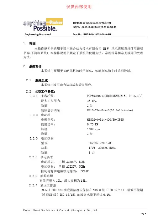
国电联合动力技术有限公司3MW风机液压系统使用说明书Engineering Document Doc No.: PHBJ-IM-10052-A0-0-SH1. 范围本操作说明书适用于国电联合动力技术有限公司3MW风机液压系统使用说明书(以下简称系统); 本操作说明书规定了系统的使用方法,常规保养和常见故障的处理方法。
2. 系统简介本系统主要用于3MW风机的转子刹车,偏航刹车和主轴插销控制。
2.1 系统组成本系统由液压动力站总成和管道组成。
2.2 主要工作参数:2.2.1 主齿轮泵: PGP502A0012CH1H1NE3E2B1B1 (1.2ml/r)最大工作压力: 25 MPa数量: 1台辅应急手动泵: HP10-21A-O-N-B(10.6ml/stroke)2.2.2 电动机电机型号: MS802-4-B14-400/50-IP55输出功率: 0.75 KW转速: 1500 rpm数量: 1台2.2.3 电加热器型号: SK7787-220-170功率: 170W 220VAC 50Hz数量: 1 台2.2.5 供电要求电动机为:三相 AC400V, 50Hz电加热器: 单相 AC220V, 50Hz控制电源和电磁铁电源为: DC24V2.2.6 油箱容积有效容积为12L,最大容积为15L。
2.2.7 液压工作液Mobil SHC 524油液清洁度应保持在NAS 8级(ISO 17/14),最低不能超过NAS9级( ISO 18/15),油液含水量不超过0.1%。
2.3 外形及安装说明外形, 外接管路及地脚螺钉尺寸见所附外形图3. 工况说明:系统液压回路及相关的技术参数见液压系统原理图和附件样本。
系统由电机泵组(6,7,8)提供动力, 系统压力由溢流阀(13.1)调整至170bar,蓄能器(22,23)提供应急动力源, 压力传感器(19.3)监控主系统压力, 压力传感器(19.2)监控偏航刹车压力, 压力传感器(19.1)监控主轴刹车压力,节流阀(24)平时处于关断状态, 在泵卸荷时才需要开启.3.1 转子制动回路转子制动器系统用来停止转子。
派克汉尼汾公司版权所有未经许可不能摘录,翻印。
保留修改权利2021年6月警告销售条件本样本中产品和/或系统或相关产品出现故障,选型不当或使用不当,均可能导致人身伤亡和财产损失。
本文档以及由派克·汉尼汾公司及其子公司和授权经销商提供的其他资料,为具有技术知识的用户提供进一步研究所需的产品和/或系统选项。
重要的是,用户必须对您的应用进行全面的分析,并对当前产品样本中与产品或系统相关的资料进行评估。
由于工作条件以及产品或系统的多样性,用户必须自行分析和测试,并独自承担一切后果,包括:产品和系统的最终选型以及确保满足应用的所有性能、安全和警告等方面的要求。
派克·汉尼汾及其子公司可能会随时对本样本中的产品,包括但不限于:产品的特性、产品的规格、产品的结构、产品的有效性以及产品的价格作出变更而不另行通知.本样本中的所有产品均由派克·汉尼汾公司及其子公司和援权经销商销售。
与派克签订的任何销售合同均按照派克标准条件和销售条件中规定的条款执行(提供复印件备索)。
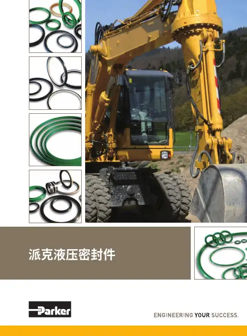
本公司的密封件,只能在本公司的文件资料述及的应用参数范围与接触介质、压力、温度和存放时间相一致的情况下才能使用。
在规定的应用参数范围外使用以及错误选用不同的材料都可能导致密封件寿命的缩短以及设备的损坏,甚至更严重的后果(如生命安全,环境污染等)。
样本中所列出的工作压力、温度范围、运动速度是极限值,它们之间相互关联、相互影响;在极端的工况下,建议不要同时把各个参数都同时用到极限值。
对于特殊的要求(压力、温度、速度、介质等),请联系派克汉尼汾公司以咨询合适的密封结构、材料、配置、安装建议等。
由于诸多工作参数会影响到流体传动系统及密封元件,这些设备的制造商必须在实际工作条件下测试、验证并批准密封系统的功能与可靠性。
此外,对于不断出现的新的介质(液压油、润滑脂、清洗剂等),用户特别注意它们与目前所用的密封件弹性体材料的兼容性。
我们建议用户在大批量应用之前,在厂内或现场先做密封材料的兼容性能测试,作为密封产品与系统供应商,我们建议用户遵循我们的这些建议。
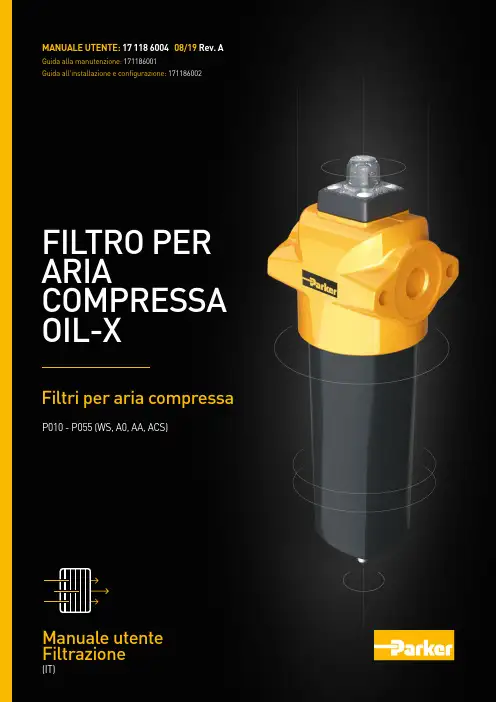
FILTRO PER ARIACOMPRESSA OIL-XFiltri per aria compressaMANUALE UTENTE: 17 118 6004 08/19 Rev. AGuida alla manutenzione: 171186001Guida all'installazione e configurazione: 171186002Manuale utente FiltrazioneP010 - P055 (WS, A0, AA, ACS)0405091116131819222123201217071014– Installazione del sistema OIL-X– Raccomandazioni per l'installazione– Codifica dei modelli– Portate del separatore d'acqua– Portate del filtro – Dati tecnici– Portate del filtro– Dichiarazione di conformità– Accessori/Ricambi– Parker nel mondo– Pesi e dimensioni del filtro– Depressurizzazione del sistema – Rimozione del bicchiere del filtro– Rimozione di elementi del bicchiere del filtro – Sostituzione dello scarico automatico– Etichetta di promemoria manutenzione – Procedura di avviamento del sistema– Intervalli di manutenzione– I nserimento di elementi di ricambio nel bicchiere del filtro– S ostituzione della guarnizione dell'o-ring della testa del filtro– Reinstallazione del bicchiere nella testa del filtro– Procedura di avviamento – Configurazione di esercizio– P esi e dimensioni del separatore d'acqua– Video: GuidaRACCOMANDAZIONI PER L'INSTALLAZIONERACCOMANDAZIONI PER L'INSTALLAZIONESi raccomanda che l'aria compressa venga trattata prima dell'ingresso nel sistema di distribuzione e nei punti di utilizzo/applicazioni critici.L'installazione di essiccatori per aria compressa in un sistema precedentemente umidificato potrebbe generare ulteriore sporco nei filtri sul punto di utilizzo durante l'essiccazione del sistema di distribuzione.In questo periodo potrebbe essere necessario cambiare gli elementi filtranti più frequentemente.Nelle installazioni in cui sono utilizzati compressori senza olio e sono ancora presenti aerosol d'acqua e particolato, devono essere ancora utilizzati gradi generici e ad alta efficienza.Un filtro per uso generico deve sempre essere installato per proteggere il filtro ad alta efficienza da aerosol di liquidi dispersi e particolato solido. Installare un'apparecchiatura di depurazione alla temperatura più bassa oltre il punto di congelamento, preferibilmente a valle di postraffreddatori e serbatoi d'aria.Il punto di utilizzo dell'apparecchiatura di depurazione deve essere installato il più vicino possibile all'applicazione.L'apparecchiatura di depurazione non deve essere installata a valle di valvole ad apertura rapida e deve essere protetta da eventuali flussi inversi o urti.Spurgare tutte le tubazioni in ingresso nell'apparecchiatura di depurazione prima dell'installazione, dopo l'installazione e prima della connessione all'applicazione finale.Se le linee di bypass sono installate attorno all'apparecchiatura di depurazione, assicurarsi che venga fornita una filtrazione adeguata alla linea, per evitare la contaminazione del sistema a valle.Installare le linee di scarico dai filtri a coalescenza direttamente in un separatore di condensa. Se non è possibile collegare le linee di scarico direttamente a un separatore, sfiatare le linee in un manifold di condensa (dotato di sfiato a un'estremità) e quindi in un unico ingresso di un separatore di condensa.Incaricare un'azienda preposta per lo smaltimento dei liquidi raccolti dall'apparecchiatura di filtrazione.I liquidi raccolti devono essere trattati e smaltiti responsabilmente.PROCEDURA DI AVVIAMENTOPrima di pressurizzare il filtro, assicurarsi che la testa e il bicchiere siano installati in modo appropriato e che il blocco sia allineato correttamente. Aprire lentamente la valvola di ingresso (01) per pressurizzare gradualmente il filtro e attendere 1 minuto (02) prima di aprire lentamente la valvola di uscita (03) per ripressurizzare le tubazioni a valle.Nota: non aprire le valvole di ingresso o uscita rapidamente né sottoporre l'unità a una pressione differenziale eccessiva, in quanto possono verificarsi danni.0 bar7 bar0103WSAAAO 1 minuto02WSAAAOMANUTENZIONE DEL PRODOTTOINTERVALLI DI MANUTENZIONEPer prestazioni ottimali del filtro, gli elementi filtranti a coalescenza e anti-particolato asciutto OIL-X Grado AO e OIL-X Grado AA devono essere sostituiti ogni 12 mesi (8736 ore) insieme allo scarico automatico con galleggiante.A differenza degli elementi filtranti a coalescenza e anti-particolato asciutto, che vengono sostituiti annualmente per garantire laqualità dell'aria compressa, la durata dell'elemento filtrante ad adsorbimento e della cartuccia può dipendere da vari fattori e richiedere sostituzioni più frequenti. I fattori che influiscono sulla durata dei filtri ad adsorbimento sono:Concentrazione dei vapori d'olioMaggiore è la concentrazione di vapore d'olio in ingresso, più rapidamente si esaurisce la capacità del materiale di adsorbimento, con conseguente riduzione della durata dell'elemento filtrante ad adsorbimento e della cartuccia.Grandi quantità di olioI filtri ad adsorbimento sono progettati solo per ridurre vapori di olio e odori, non olio liquido o sospensioni di olio. Un prefiltraggio con scarsa manutenzione o inesistente (filtri a coalescenza) causa il rapido esaurimento della capacità del filtro con conseguente rapida riduzione della durata dell'elemento filtrante ad adsorbimento e della cartuccia.TemperaturaIl contenuto di vapori di olio aumenta in modo esponenziale rispetto alla temperatura di ingresso, riducendo la durata dell'elemento filtrante ad adsorbimento e la cartuccia. Inoltre, nella misura in cui aumenta la temperatura, la capacità di adsorbimento del materiale adsorbente diminuisce, riducendo ulteriormente la durata dell'elemento filtrante ad adsorbimento e della cartuccia.Umidità relativa e punto di rugiadaL'aria umida riduce la capacità di adsorbimento del materiale adsorbente e la durata dell'elemento filtrante ad adsorbimento e della cartuccia. In teoria, i filtri ad adsorbimento in linea devono sempre essere installati a valle dell'essiccatore per aria compressa per prolungare la durata degli elementi filtranti ad adsorbimento e della cartuccia.Cambio dell'olio del compressoreQuando si cambia l'olio del compressore, il nuovo lubrificante brucia "componenti leggeri", aumentando il contenuto di vapore di olio per ore o settimane dopo il cambio. Questo incremento del contenuto di vapore di olio viene adsorbito dall'elemento filtrante o dalla cartuccia, riducendone la durata.Filtri ad adsorbimento OIL-X Grado ACSL'elemento OIL-X Grado ACS offre prestazioni ottimali a una temperatura di ingresso nominale di 21 °C, con punto di rugiada in pressione a -40 °C e concentrazione massima di vapore di olio di ingresso di 0,018 mg/m3. In queste condizioni il filtro OIL-X Grado ACS avrà una durata di 650 ore. L'uso del filtro OIL-X Grado ACS a temperature di ingresso/concentrazioni di vapore di olio di ingresso superiori o a monte di un essiccatore ad adsorbimento o frigorifero riduce la durata del filtro ad adsorbimento. Sostituire l'elemento filtrante a carbone se si rilevano vapori, odori o sapori. I filtri OIL-X Grado ACS sono raccomandati per applicazioni al punto di utilizzo solo dove la sostituzione degli elementi con più frequenza è accettabile.Filtr iA differenza dei filtri ad adsorbimento in linea (OIL-X Grado ACS), i filtri ad adsorbimento OIL-X Grado OVR sono dimensionati e selezionati non solo per fornire aria di qualità costante ma anche per garantire una durata della cartuccia di 12 mesi. La durata di 12 mesi (6000 ore per modelli OVR 100 ~ OVR 250 e 8736 ore per modelli OVR 300 ~ OVR 550) della cartuccia dipende dal dimensionamentodei seguenti parametri di ingresso: temperatura di ingresso massima/tipo di compressore, pressione di ingresso minima, posizione nel sistema (a monte o a valle dell'essiccatore) e contenuto di vapori di olio. Il filtri ad adsorbimento OIL-X Grado OVR sono progettati sia per l'intero impianto (sala compressori) che per applicazioni al punto di utilizzo.Chiudere lentamente le valvole di ingresso (01) e di uscita (02) e depressurizzare il filtro (03) utilizzando lo scarico.Svitare il bicchiere del filtro (01 e 02) e rimuovere gli elementi utilizzati (03).Nota: per rimuovere il bicchiere dei filtri 050 e 055 potrebbe essere necessaria una chiave a nastro.Attenzione0 bar/0 psi010203Attenzione0 bar/0 psiGuanti di protezioneSmaltire in modo sicuro0102Rimuovere l'elemento del bicchiere del filtro.Svitare lo scarico automatico (01) e smaltirlo (02). Installare il nuovo scarico (03) e serrarlo (04).2,5 N/mSmaltire in modo sicuro0104030203Inserire il nuovo elemento nel bicchiere del filtroaccertandosi che i capicorda siano posizionati correttamente nelle scanalature.Sostituire l'o-ring posto nella testa del filtro con il nuovo o-ring fornito.Reinstallare il bicchiere e la testa del filtro accertandosi che le filettature siano completamente inserite (01) e i blocchi siano allineati (02).Nota: per garantire che il bicchiere sia completamente inserito nella testa, è necessaria una rotazione di 360° fino all'arresto filettato per il bicchiere 010-030, di 720° per il bicchiere 035-045 e di 540° per il bicchiere 050-055.Accertasi di lubrificare l'o-ring e le filettature con un tipo di vaselina priva di acidi adeguato.0201Fino a 720°Non aprire le valvole diingresso o uscita rapidamentené sottoporre l'unità a unapressione differenzialeeccessiva, in quanto possonoverificarsi danni.Attaccare l'etichetta con la data di sostituzione dell'elemento al bicchiere del filtro e annotarvi sopra la data della sostituzione successiva, ad esempio dopo 12 mesi.Aprire lentamente la valvola di ingresso (01) per pressurizzare gradualmente il filtro e attendere 1 minuto (02) prima di aprire lentamente la valvola di uscita (03) per ripressurizzare le tubazioni a valle.Non utilizzaresolventi o alcol perpulire le etichette inquanto ciò potrebbecausare danni.0 bar/0 psi7 bar/100 psi011 minuto0203PROBLEMI? GUARDATE LA GUIDAGuarda la guida sul sito Web Parker Hannifin CONTENUTO DEL VIDEOInstallazione del sistema OIL-XProcedura di avviamentoDepressurizzazione del sistemaRimozione del bicchiere del filtroRimozione di elementi dal bicchiere del filtroSostituzione dello scarico automaticoInserimento di elementi di ricambio nel bicchiere del filtroSostituzione della guarnizione dell'o-ring della testa del filtroReinserimento del bicchiere nella testa del filtroEtichetta di promemoria manutenzioneProcedura di avviamento del sistemaSPECIFICHE TECNICHEESEMPIO DI CODIFICA DEI MODELLISCELTA DEL PRODOTTOI valori di portata indicati si riferiscono al funzionamento a 7 bar g (100 psi g), con valori di riferimento a 20o C, 1 bar (a), 0% di pressione relativa al vapore acqueo.Per valori di portata in presenza di altri livelli di pressione applicare i fattori correttivi indicati.MODELLO A = 1/4"B = 3/8"C = 1/2"D = 3/4"E = 1"G = 1 1/2"H = 2"I = 2 1/2"J = 3"G = BSPP N = NPTF = Galleggiante M = ManualeX = Nessuno I = Monitor criticitàWS AO AA ACS030PCodice a 3 cifre come mostrato di seguitoPORTATE DEL SEPARATORE D'ACQUACFP – Fattore di correzione della pressione minima di ingresso (separatori d'acqua)MODELLODIMENSIONIATTACCOL/SM 3/MINM 3/HCFMP010A P020D P045I P010C P035G P025E P055JP010B P025D P050I P015C P040H P030G [ ][ ][ ][ ][ ][ ][ ][ ][ ][ ][ ][ ][ ][ ][ ][ ][ ][ ][ ][ ][ ][ ][ ][ ][ ][ ][ ][ ][ ][ ][ ][ ][ ][ ][ ][ ][ ][ ][ ]¼¾2 ½½1 ½1½13⅜¾2 ½½2104035010350110800101108004.2 2-235EPDM 1100,62,421,00,621,06,648,00,66,648,02,421,06,636144126036126039628803639628801441260396218574221742233169521233169585742233161514131211109876543212322182031891741601451311161008773584429150,680,710,730,760,790,820,850,890,941,001,141,331,592,002,634,00DATI TECNICIMODELLOMODELLI DI FILTROMIN. DI ESERCIZIO PRESSIONE MAX DI ESERCIZIO PRESSIONE MIN. RACCOMANDATA TEMP . DI ESERCIZIO MAX RACCOMANDATA TEMP . DI ESERCIZIOBAR GBAR GOCOCPSI GPSI GOFOFNota: i filtri di grado AO/AA/WS per l'uso fino a 16 bar g (232 psi g) sono forniti con scarico galleggiante [F] di serie.Per pressioni da 16 a 20 bar g (da 232 a 290 psi g), è necessario utilizzare uno scarico manuale [M].I filtri di grado ACS sono forniti con scarico manuale [M] di serie.P010P010P010P010P010P010055055055055055055[ ][ ][ ][ ][ ][ ][ ][ ][ ][ ][ ][ ][ ][ ][ ][ ][ ][ ][ ][ ][ ][ ][ ][ ]F M M FFM F M M FFM [ ][ ][ ][ ][ ][ ][ ][ ][ ][ ][ ][ ]11111116202016162015151515151523229029023223229022222235353535353580100100808050176212212176176122––––––P030G P050I P040H P055JP035G P055I P045I 1 ½2 ½231 ½2 ½2 ½1104302206201606203306,625,813,237,39,637,319,823391146613143391314699P030P050P040P055P035P055P0453961548792223257622321188PORTATE DEL FILTROCFP – Fattore di correzione della pressione minima di ingresso (filtri a coalescenza e anti-particolato asciutto)MODELLODIMENSIONI ATTACCOL/SM 3/MINKIT ELEMENTI DI RICAMBIOM 3/HCFMN.P010A P020C P010C P025D P010B P020D P015C P025E ¼½½¾⅜¾½110301060103020600,61,80,63,60,61,81,23,6216421127216442127P010P020P010P025P010P020P015P025[Grado][Grado][Grado][Grado][Grado][Grado][Grado][Grado][Grado][Grado][Grado][Grado][Grado][Grado][Grado]111111*********3610836216361087221616201519141813171211109876543212322902182772032631892481741601451311161008773584429150,680,710,730,760,790,820,850,890,941,001,141,331,592,002,634,00[ ][ ][ ][ ][ ][ ][ ][ ][ ][ ][ ][ ][ ][ ][ ][ ][ ][ ][ ][ ][ ][ ][ ][ ][ ][ ][ ][ ][ ][ ][ ][ ][ ][ ][ ][ ][ ][ ][ ][ ][ ][ ][ ][ ][ ]PESI EDIMENSIONI DEL SEPARATORE D'ACQUAPESI E DIMENSIONI DEL SEPARATORE D'ACQUAMODELLOTUBO MISURAALTEZZA (H)(A)LARGHEZZA (L)(B)PROFONDITÀ (P)(C)PESOMMMMMMMMMMMMKGINSINSINSINSINSINSLB¼13½1 ½¾2 ½⅜1 ½½2¾2 ½180277516180440238440180277238440277516154232444154383202383154232202383232444761201927616489164761208916412019250701205010050100507050100701206509021836515784157650902841570902183383840383838383838383838400,802,6410,830,786,691,356,280,792,541,086,462,6410,807,0910,9120,317,0917,329,3717,327,0910,919,3717,3210,9120,316,069,1317,486,0615,087,9515,086,069,137,9515,089,1317,482,994,727,562,996,463,56,462,994,723,56,464,727,561,972,764,721,973,941,973,941,972,761,973,942,764,722,564,537,202,566,183,316,182,564,533,316,184,537,201,51,51,571,51,51,51,51,51,51,51,51,51,571,765,8323,891,7214,742,9813,851,755,612,3914,235,8323,81WSP010A WSP025E WSP055JWSP010C WSP035G WSP020D WSP045I WSP010B WSP030G WSP015C WSP040H WSP025D WSP050I Nota: i separatori d'acqua non presentano alcun indicatore DP , utilizzare le dimensioni H + d per l'altezza complessiva.Diametro del tubo (dimensioni attacco)bicchiere rimozione GiocoW ACHBDPESI EDIMENSIONI DEL FILTROPESI E DIMENSIONI DEL FILTROMODELLOTUBO MISURAALTEZZA (H)(A)LARGHEZZA (L)(B)PROFONDITÀ (P)(C)PESOMMMMMMMMMMMMKGINSINSINSINSINSINSLB¼¾2 ½3½1 ½½2⅜1½1 ½¾2 ½2 ½1802776548441803672385321802772384402385328441542325827721543222024751542322023832024757727612019219276120891647612089164891641925070120120507050100507050100501001206509021831836509028415765090284157841571833232686832323868323232683268680,842,1410,3015,300,823,041,177,300,842,691,166,901,447,1015,97,0910,9125,7533,237,0914,459,3720,947,0910,919,3717,3210,9120,9433,236,069,1322,9130,396,0612,687,9518,76,069,137,9515,077,9518,730,392,994,727,567,562,994,723,56,462,994,723,56,463,56,467,561,972,764,724,721,972,761,973,941,972,761,973,941,973,944,722,564,537,207,202,564,533,316,182,564,533,316,183,316,187,201,51,51,571,571,51,51,51,51,51,51,51,51,51,51,571,864,7122,7133,731,816,702,5816,091,865,922,5515,213,1915,6535,05P010A P025D P050I P055JP010C P030G P020C P040H P010B P025E P015C P035G P020D P045I P055I W ACHBDDiametro del tubo (dimensioni attacco)Gioco rimozione bicchiereCMODELLI DI FILTRON. CAT.INDICE010010010025 – 030025 – 030025 – 030015 – 020015 – 020015 – 020035 – 045035 – 045035 – 045050 – 055050 – 055035 – 055010 – 055TRK1-2MBK1-1MBK1-2TRK3-2MBK3-1MBK3-2TRK2-2MBK2-1MBK2-2TRK4-2MBK4-1MBK4-2TRK5-2MBK5-1ZD90GL EM1ACCESSORI/RICAMBI (KIT DI MANUTENZIONE)PARKER NEL MONDOAE – EAU, DubaiTel.: +971 4 8127100********************AR – ARGENTINA, Buenos AiresTel.: +54 3327 44 4129AT – AUSTRIA, Wiener NeustadtTel.: +43 (0)2622 23501-0*************************AT – EUROPA ORIENTALE,Wiener NeustadtTel.: +43 (0) 2622 23501 900****************************AU – AUSTRALIA, Castle HillTel.: +61 (0)2-9634 7777AZ – AZERBAIGIAN, BakuTel.: +994 50 2233 458****************************BE/LU – BELGIO, NivellesTel.: +32 (0) 67 280 900*************************BR – BRASILE, Cachoeirinha RSTel.: +55 51 3470 9144BY – BIELORUSSIA, MINSKTel.: +375 17 209 9399*************************CA – CANADA, Milton, OntarioTel.: +1 905 693 3000CH – SVIZZERA, EtoyTel.: +41 (0)21 821 87 00*****************************CL – CILE, SantiagoTel.: +56 2 623 1216CN – CINA, ShanghaiTel.: +86 21 2899 5000CZ – REPUBBLICA CECA, KlecanyTel.: +420 284 083 111*******************************DE – GERMANIA, KaarstTel.: +49 (0) 2131 4016 0*************************DK – DANIMARCA, BallerupTel.: +45 43 56 0400*************************ES – SPAGNA, MadridTel.: +34 902 330 001***********************FI – FINLANDIA, VantaaTel.: +358 (0) 20 753 2500*************************FR – FRANCIA, Contamine s/Arve Tel.: +33 (0)4 50 25 80 25************************GR – GRECIA, Atene Tel.: +30 210 933 6450************************HK – Hong Kong Tel.: +852 2428 8008HU – UNGHERIA, Budapest Tel.: +36 1 220 4155*************************IE – IRLANDA, Dublino Tel.: +353 (0) 1 466 6370*************************IN – INDIA, Mumbai Tel.: +91 22 6513 7081-85IT – ITALIA, Corsico (MI)Tel.: +39 02 45 19 21***********************JP – GIAPPONE, Tokyo Tel.: +81 (0) 3 6408 3901KR – COREA DEL SUD, Seul Tel.: +82 2 559 0400KZ – KAZAKISTAN, Almaty Tel.: +7 7272 505 800****************************LV – LETTONIA, Riga Tel.: +371 6 745 2601************************MX – MESSICO, Apodaca Tel.: +52 81 8156 6000MY – MALESIA, Shah Alam Tel.: +60 3 7849 0800NL – Paesi Bassi,Oldenzaal Tel.: +31 (0) 541 585 000********************NO – NORVEGIA, Asker Tel.: +47 66 75 34 00************************NZ – NUOVA ZELANDA, Mt Wellington Tel.: +64 9 574 1744PL – POLONIA, Varsavia Tel.: +48 (0)22 573 24 00************************PT – PORTOGALLO, Leca da Palmeira Tel.: +351 22 999 7360**************************RO – ROMANIA, Bucarest Tel.: +40 21 252 1382*************************RU – RUSSIA, Mosca Tel.: +7 495 645-2156************************SE – SVEZIA, Spånga Tel.: +46 (0)8 59 79 50 00************************SG – Singapore Tel.: +65 6887 6300SK – SLOVACCHIA, Banská Bystrica Tel.: +421 484 162 252**************************SL – SLOVENIA, Novo Mesto Tel.: +386 7 337 6650**************************TH – TAILANDIA, Bangkok Tel.: +662 717 8140TR – TURCHIA, Istanbul Tel.: +90 216 4997081************************TW – TAIWAN, Taipei Tel.: +886 2 2298 8987UA – UCRAINA, Kiev Tel.: +380 44 494 2731*************************UK – REGNO UNITO,Warwick Tel.: +44 (0) 1926 317 878********************US – USA, Cleveland Tel.: +1 216 896 3000VE – VENEZUELA, Caracas Tel.: +58 212 238 5422ZA – SUD AFRICA,Kempton Park Tel.: +27 (0) 11 961 0700*****************************22Filtro per aria compressa OIL-X - Manuale utente. ©2019.Centro informazioni prodotti per l'Europa Numero verde: 00 800 27 27 5374(da AT, BE, CH, CZ, DE, EE, ES, FI, FR, IE, IL, IS, IT, LU, MT, NL, NO, PT, SE, SK, UK)GARANZIA DI UN ANNO SULLAQUALITÀ DELL'ARIALa garanzia della qualità dell'aria ha durata di 1 anno e si rinnova a ogni sostituzione annuale degli elementi filtranti.Le sostituzioni annuali degli elementi filtranti garantiscono:• Prestazioni ottimali costanti• Qualità dell'aria sempre conforme agli standard internazionali• Protezione delle apparecchiature a valle, del personale e dei processi• Costi operativi ridotti• Maggiore produttività e redditività• TranquillitàPARKER HANNIFIN MANUFACTURING LIMITEDGas Separation and Filtration Division EMEADukesway, Team Valley Trading EstGateshead, Tyne and WearInghilterra NE11 0PZTel.: +44 (0) 191 402 9000Fax: +44 (0) 191 482 6296/gsfe© Parker Hannifin Corporation. Tutti i diritti riservati.。
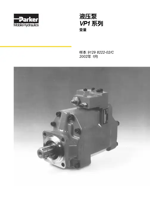
液压泵VP1 系列变量样本 9129 8222-02/C 2002年 1月3-10- 2Parker Hannifin Corporation Hydraulics Group (Europe)轴向柱塞泵 - 变量VP1 系列样本 HY02-8029/C技术资料派克公司保留改进产品的权力,恕不预先告之。
尽管样本不断校对和修改,也有出错的可能性,有关产品的更进一步详细资料请与派克公司(工程机械部)联系。
目录页码 3-10-概述3设计3技术规格4订货资料4VP1 剖视图4安装尺寸5管路直径5BPV-VP1 旁通阀6FDV-VP1 卸荷阀6VP1 管接头套件6VP1 在负载传感系统中7 VP1-LS 负载传感控制8通轴连接9安装和起动10换算系数1 kg 2.20 lb 1 N 0.225 lbf 1 Nm 0.738 lbf ft 1 bar 14.5 psi 1 l 0.264 US gallon 1 cm 30.061 cu in 1 mm 0.039 in 9/5°C + 32 1 °F3-10- 3Parker Hannifin Corporation Hydraulics Group (Europe)轴向柱塞泵 - 变量VP1 系列样本 HY02-8029/C技术资料3设计大角度—紧凑设计泵的设计允许柱塞和滑履/斜盘间的角度大(20o ),因此结构紧凑,外部尺寸小。
通轴驱动允许通轴和另一个泵联接,例如和系列F1定量泵。
承受较大的外部轴载荷重型滚柱轴承允许径向作用在VP1的轴端,因此可以不用另外的轴承就把齿轮直接装在轴上。
寿命长VP1 泵设计用于具有负载传感系统的车辆,既坚固又简单,仅有几个运动零件,可靠性高,使用寿命长。
VP1 是世界上第一台用于车辆应用的变量泵,它能够和变速箱动力输出轴紧偶合或者和满足ISO 标准7653-1985的独立动力输出轴(例如发动机动力输出轴)联接。
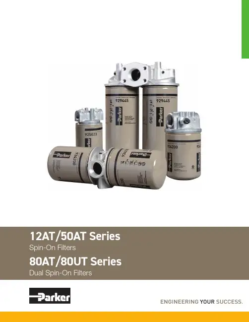
212AT/50AT80AT/80UT SeriesSpin-On FiltersApplications for Spin-On Filters• Mobile Equipment • Hydrostatic Drives • Industrial Power Units • Reservoir BreathersMounting•for flexibilityGauges/Switches • Identifies element condition during operation• No mess, oil is contained inside • Easy to handle • Single anddouble length filters for longer lifePorts• Both NPT and SAEstraight thread connections available. SAE Code 61 Flange on 80AT.Interchangeability • Parker canisters fit manycompetitors' heads. Contact Hydraulic & Fuel Filtration Division, search the Par<>Fit Toolkit at , or download our app.Parker’s latest range of Spin-On filter technology provides users withreliable performance in a lightweight, compact and cost effective package. These solutions provide protection to critical system components in a variety of low pressure applications.In addition to increased flow rates, Parker has expanded the product family to include new filter head configurations and flanged porting along withconsistency in filter element condition options.Recognized as a leader in product quality, Parker applies the latest in designand manufacturing techniques to deliver on our promise.Spin-On filters can be used in suction and return line filterapplications with pressures to 150 psi (10.3 bar).Improving system fluid cleanliness levels, providing better cold start performance and meeting service interval expectations are the primary objectives in the AT/UT series design. Parker filters utilize several types of filtration media to meet the demanding requirements of today’s applications.• Cellulose MediaThe original and most common media is made of naturalfibers. These twisted fibers are larger and more irregular than synthetic fibers — creating more resistance to flow or pressure drop.• Synthetic MediaThese man-made glass fibers are very uniform in size and shape — creating the least possible resistance to flow and providing improved efficiency to protect sensitive controls. • Par-Gel MediaA highly absorbent copolymer laminate with an affinity for water — allows hydraulic or lubrication fluid to pass freely but water is bonded to the media and forever removed from the system.312AT/50AT/80AT/80UT SeriesPerformanceFlow vs. Pressure LossLPM GPMP S I DB A R12AT -1 AssemblyLPMGPMP S I DB A R12AT -2 Assembly1086420LPM GPMP S I DB A R50AT -1 Assembly30252015105LPMGPMP S I DB A R30252015105LPMGPMP S I DB A R80AT -1 Assembly80UT -1 Assembly1086420LPM GPMP S I DB A R50AT -2 Assembly161412108642GPMP S I DB A RLPM181614121086420GPMP S I DB A R LPM80UT -2 Assembly80AT -2 AssemblyInstallation and Specification DataPressure Rating:Maximum AllowableOperating Pressure (MAOP): 150 psi (10.3 bar)Design Safety Factor: 2.5:1Operating Temperatures:-40ºF to 225ºF (-40ºC to 107ºC)Canister Collapse Rating:100 psid minimumCanister Condition Indicators:Gauge: Color coded 15/25 psi Gauge: Color coded vacuum Pressure Switch: Normally open 20 +/- 2 psi 5 Amps @ 24 VDC Vacuum Switch: Normally open 5" +/- 1" Hg 1.0 Amp @ 120 VAC Filter Material: Head: AluminumCanister: Low Carbon Steel Shipping Weights (approximate):Single length: 1.6 lbs.Double length: 2.7 lbs.Drawings are for reference only. Contact factory for current version.Spin-On FiltersLinear Measure: millimeterinchThread DepthDia 4Spin-On FiltersPressure Rating:Maximum AllowableOperating Pressure (MAOP): 150 psi (10.3 bar)Design Safety Factor: 2.5:1Operating Temperatures:-40ºF to 225ºF (-40ºC to 107ºC)Canister Collapse Rating:100 psid minimumCanister Condition Indicators:Gauge: Color coded 15/25 psi Gauge: Color coded vacuum Pressure Switch: Normally open 20 +/- 2 psi 5 Amps @ 24 VDC Vacuum Switch: Normally open 5" +/- 1" Hg 1.0 Amp @ 120 VAC Filter Material: Head: AluminumCanister: Low Carbon Steel Shipping Weights (approximate):Single length: 3.9 lbs.Double length: 4.8 lbs.Installation and Specification DataDrawings are for reference only. Contact factory for current version.Linear Measure: millimeterinch127.805.0357.152.2529.201.1525.401.005DiaInstallation and Specification DataPressure Rating:Maximum AllowableOperating Pressure (MAOP): 150 psi (10.3 bar)Design Safety Factor: 2.5:1Operating Temperatures:-40ºF to 225ºF (-40ºC to 107ºC)Canister Collapse Rating:100 psid minimumCanister Condition Indicators:Gauge: Color coded 15/25 psi Gauge: Color coded vacuum Pressure Switch: Normally open 20 +/- 2 psi 5 Amps @ 24 VDC Vacuum Switch: Normally open 5" +/- 1" Hg 1.0 Amp @ 120 VAC Filter Material: Head: AluminumCanister: Low Carbon Steel Shipping Weights (approximate):Single length: 11.3 lbs.Double length: 13.0 lbs.Drawings are for reference only. Contact factory for current version.Dual Spin-On FiltersLinear Measure: millimeterinchNPT Integral ThreadsGauge Port (4 places)Torque to 2-3 turns from finger tight6Ports (Both Ends) Integral Threads+1DANGER!Read and followall safety instructions.Failure to do so could resultin serious bodily injury ordeath.2. Turn off power supply topumping unit.3. Tag pumping unit out ofservice for filter change.4. Remove the old filter, whilecollecting all spilled fluid.Dispose of the old filter inaccordance with local, stateor federal regulations.5. Apply a thin film oflubricating oil to the gasketof the new filter.6. Thread new filter on the flowadapter or manifold untilthe gasket makes contact.Tighten according to filterlabel.7. Turn on fluid supply.8. Pressurize the system andcheck for leaks.WARNING! A pressuredifferential indicator mustbe installed for any systemcapable of generating morethan 25 psid across the filter.2. Filter unit must be installedusing a suitable mountingdevice or rigid piping.3. Filter unit must be installedwith flow in proper direction.4. Filter should be inspectedevery six months andchanged annually when slowflow occurs.5. Water absorbing filters- when the differentialpressure reaches 20-25 psidthe filter could be pluggedwith water and shouldbe immediately replaced.Failure to replace couldresult in internal filter ruptureresulting in water downstream.Spin-On Filters8Return Line Applications1. 25 lb bypass in flow adapterrecommended.2. Filter unit must be installedin the circuit just before thereservoir. DO NOT use ashutoff valve in the returnline for the filter that is beingchanged. A check valve isacceptable.3. Filter unit must be sizedto accept the total flowduring discharging from thecylinders and actuators.Suction Side Applications1. 3-5 lb bypass in flowadapter recommended toprevent pump cavitation.2. A vacuum gauge isrecommended to monitorfilter condition.3. Cavitation of the pump canbe a problem with the filteron the suction line. Alwaystry to minimize restriction byover sizing the filter, or byusing a microglass media.6. If water stoppage issuspected, remove the waterabsorbing filter and pour thecontents in a jar. If fluid iscloudy or water separates inthe jar, the filter is most likelyplugged with water. If wateris excessive in the jar it maybe necessary to have thetank cleaned or drained priorto further use.Spin-On FiltersAccessory Parts ListIndicating Pressure Gauge (15 PSI)Indicating Pressure Gauge (25 PSI)Pressure Switch1/8-27NPTF Vacuum Switch Linear Measure: millimeterinch1/8 NPTSeals IncludedIndicating Vacuum Gauge9Spin-On FiltersReservoir BreatherSizingSelect the proper size canister for the maximum rate of reservoir draw down or air exchange rate. As a rule of thumb, clean pressure drop should be limited to 0.18 psid (5" H 2O).A pipe flange, weld collar, etc. may be used to connect the adapter kit to the reservoir. Make sure that air is not able to leak around the adapter. When mounting on the side of the reservoir, make sure the installation is above the surface of the fluid.Recommended canister change out is after 500 hours of operation.More frequent replacement may be required when operated in heavily contaminated areas such as grinding operations, primary metal mills, and on mobile equipment. Under such conditions, increase replacement frequency to every 250 hours.* 99% Removal efficiency for particles larger than the stated size in air.Graphs are for 03C canisters only. Total pressure drop across canister, adapter, and pipe may be found by adding pressure drops below:+ 1.5% for each inch of 12AT adapter or 3/4" pipe used.+ 3.0% for each 3/4" elbow used.+ 1.0% for each inch of 50AT adapter or 1-1/4" pipe used.+ 2.0% for each 1-1/4" elbow used.Typical Installations mounted on side or top of reservoirAllow 1.25" for canisterremoval clearanceLinear Measure: millimeterinch1012AT/50AT/80AT/80UT SeriesSpin-On FiltersHow T o OrderSelect the desired symbol (in the correct position) to construct a model code.Example:Notes:1. Selecting 80AT or 80UT in Box 1 requires the selection of “G” in Box 6 and “H” in box 8.2. Nominal flow rates for single length filters: 12AT - 12GPM; 50AT - 35 GPM; 80AT/80UT - 55 GPM.Replacement Canisters11Aerospace Filtration Division Greensboro, North Carolina 336 668 4444Bioscience & Water Filtration Division Bioscience Filtration Oxnard, California877 784 2234Water PurificationCarson, California310 608 5600Engine Mobile Aftermarket Division Kearney, Nebraska308 234 1951Engine Mobile Original Equipment Division Modesto, California209 521 7860HVAC Filtration Division Industrial Gas Filtration &Generation DivisionLancaster, NY800 343 4048Industrial ProcessFiltration DivisionMineral Wells, T exas940 325 2575Bioscience EngineeringFiltration Division EMEABirtley, United Kingdom+44 (0) 191 410 5121Engine Mobile FiltrationDivision EMEADewsbury, United Kingdom+44 (0) 1924 487 037Gas Separation &Filtration Division EMEAT eam Valley, United Kingdom+44 (0) 191 402 9000Australia Filtration DivisionCastle Hill, Australia+61 2 9634 7777China Filtration DivisionShanghai, China+86 21 2067 2067India Filtration DivisionChennai, India+91 22 4391 0700Korea Filtration DivisionHwaseon City, Korea+82 31 359 0852Latin America Filtration DivisionSao Paulo, Brazil+55 12 4009 3500Parker Filtration Group。
Parker’s continued focus on process optimization and control has led to the development of a new range of prefilters for the clarification and pre-stabilization stages of wine processing and packaging.The control of particulate and microbial loading is important to provide stability to wine during storage and transport and to ensure that the finished product maintains and develops its desirable characteristics after packaging.Parker’s next generation of PREPOR NG filters have been developed to remove yeast and reduce bacterial loading to improve short-term stability and to increase theservice life of downstream membrane filters. The robust componentry allows for caustic and backwash regeneration, making the filter stage a reliable and cost-effective solution to intermediate stabilization.FeaturesPerformance CharacteristicsBenefitsFiltration StageFully validated yeast removal and bacterial reduction Truly optimized graded density using unique Optimized Depth Construction (ODC) TechnologyMechanically strong and chemically resistant polypropylene construction designed for chemical CIP and backwashEffective control of clarity and microbial stability Increased filtration capacityIncreased service life when combined with regular CIP regenerationD i f f e r e n t i a l P r e s s u r e (m b a r )D i f f e r e n t i a l P r e s s u r e (p s i )PREPOR NG WineFilter Cartridges30025020015010050Flow (L / min) for liquid @ 20 °C and 1 cp 10¨moduleSpecificationsMaterials of Construction■Filtration Media: Polypropylene■Upstream Support: Polypropylene■Downstream Support: Polypropylene■Inner Support Core: Polypropylene■Outer Protection Cage: Polypropylene■End Caps: Polypropylene■End Cap Insert: 316L Stainless Steel ■O-rings: Silicone / EPDMFood Contact ComplianceMaterials conform to the relevant requirements of FDA 21 CFR Part177, current EC1935 / 2004 and current USP Plastics Class VI - 121 °C.Recommended Operating Conditions Up to 70 °C (158 °F) continuous operating temperature and higher short-term temperatures during CIP to the following limits:Effective Filtration Area (EFA)10¨ (250 mm) Up to 0.5 m2 (5.38 ft2)Cleaning and SterilizationPREPOR NG cartridges can be repeatedly steam sterilized in-situ or autoclaved up to 135 °C (275 °F). They can be sanitized with hot water up to 90 °C (194 °F), are compatible with a wide range of chemicals and can be backwashed. Please refer to our Clean-in-Place Support Guide or contact your local Parker representative for more information.Retention CharacteristicsThe absolute retention characteristics of PREPOR NG filters have been validated by challenges performed with the following organisms.Each filter cartridge displays the productname, product code and lot number.Additionally, each module displays a uniqueserial number providing full manufacturingtraceability.Performance BenefitsODC technology combines fine particleretention with increased strength andstability to enhance the performanceoffered by the PREPOR range.Temperature Max Forward dP°C °F (bar) (psi)20 68 5.0 72.540 104 4.0 58.060 140 3.0 43.580 176 2.0 29.090 194 1.0 14.5>100 (steam) >212 (steam) 0.3 4.0PNG AN--Code | Length (Nominal)Code | Micron Code | End Cap (10 inch)Code | O-ringsDS_W_01_01/23 Rev. 1C/foodandbeverage%VolumeThroughputOrganism LRV when challenged with aminimum of 107 cfu per cm2A B DSaccharomyces cerevisiae FR FR FRBrettanomyces bruxellensis FR FR FROenococcus oenos 4.0 3.0 1.0Acetobacter oeni 2.0 2.0 1.7Serratia marcescens 3.9 3.4 1.9*FR - Fully retentive during challengeWhen expressed as titre reduction “FR” equates to>107 per 10¨module.Ordering informationPREPOR NGWinePHP & PHLHOUSING RANGEAVAILABLEParker has a continuous policy of product development and although the Company reserves the right to change specifications, it attempts to keep customers informed of any alterations.This publication is for general information only and customers are requested to contact our Sales Department for detailed information and advice on a products suitability for specific applications.All products are sold subject to the company’s standard conditions of sale.。
液压注意 – 用户方责任 错误或不当地选择或使用本样本或有关资料阐述的产品,可能会导致人生伤亡及财产损失! 本样本以及其它由派克汉尼汾公司及其子公司、销售公司与授权分销商所提供的资料,仅供用户专业技术人员在对产品和系统的选型进行深入调查考证时参考。
用户应全面分析自身设备的运行工况、适用的工业标准,并仔细查阅现行的样本,以详细地了解产品及系统的相关信息,通过自己的分析和试验,对产品及系统的独立的最终选择负责,确保能满足自身设备的所有性能、耐用性、维修型、安全性以及预警功能等要求。
对于派克或其子公司或授权分销商而言,应负责按用户提供的技术资料和规范,选择和提供适当的元件或系统,而用户则应负责确定这些技术资料和规范对其设备的所有运行工况和能合理预见的使用工况是否充分和准确。
目录目录页次概述 1 订货代号 2 技术参数 4 变量控制器 5 控制选项 “C”, 压力限定(恒压)变量控制器 5 控制选项 “L”, 负载传感及压力限定变量控制器 6 控制选项 “AM”, 带遥控口的标准型先导式压力限定变量控制器 7 控制选项 “AN”, 带ISO 4401 NG06先导阀安装界面的先导式压力限定变量控制器 8 控制选项 “AE”及“AF”, 带电磁比例调节的先导式压力限定变量控制器 9 控制选项 “AMT”, “ALT”及“LOT”, 带最高压力限定的扭矩限定(恒功率)变量控制器 10 P1性能特性 11典型流量特性 11 典型总效率特性 13 典型轴输入功率特性 15 典型噪声特性 18 典型轴承寿命 20 PD性能特性 22典型流量特性 22 典型总效率特性 24 典型轴输入功率特性 26 典型噪声特性 29 典型轴承寿命 31 安装尺寸 33 P1/PD 018 33 P1/PD 028 36 P1/PD 045 40 P1/PD 060 44 P1/PD 075 49 P1/PD 100 54 P1/PD 140 59 变量控制器安装尺寸 65 可提供的扩展的液压产品 75派克汉尼汾备记派克汉尼汾概述简介, 优点派克汉尼汾简介 • 开式回路用轴向柱塞式变量液压泵 • 中压,连续工作压力280 bar • 高驱动转速型,适用于行走机械; 低噪声型,适用于工业应用 • 静音及高效的控制效能 优点 • 总结构尺寸紧凑 • 低噪声• 流量脉动小,进一步降低噪声• 采用弹性密封,不使用密封垫,从而避免外泄漏的产生• 总效率高,功耗小,减小发热• 采用带无泄漏调节装的简单变量控制器 • 符合SAE 及ISO 标准的安装法兰及油口 • 采用圆锥滚柱轴承,使用寿命长 • 全功率后驱动能力• 后部或侧面油口配置可选• 泄油口的配置对水平安装及驱动轴向上垂直安装均适用• 带有最大及最小排量调节选项 • 具有壳体至吸口单向阀选项,可延长轴封寿命 • 使用、维修方便 脉动容腔技术下列图表所示为侧向油口配置P1/PD 18, 28及45泵采用 “脉动容腔” 技术的效果,脉动容腔可降低泵出口处的压力脉动幅值40-60%,这样,无需增加成本来加装噪声缓冲元件,便可大大降低液压系统的整体噪声,P1系列 PD 系列出口压力p / bar平均压力脉动 / b a rP1 045出口压力脉动2600 rpm 无脉动容腔2600 rpm 带脉动容腔订货代号18 ml, 28 ml, 45ml派克汉尼汾P 类型 01 驱动轴 转向R 5密封材料E 油口配置0 壳体-吸口 单向阀 0 排量调节 018 排量 S 安装法兰 及油口 S 轴封 M 应用范围A 设计系列0 通轴驱动选项 C0控制选项0附加控制选项 00油漆 00修改代号系列 P D * 仅适用于045排量, “S”型安装法兰及油口00 标准型, 无修改M2 按要求修改 代号修改代号 * 适用于028及045排量 ** 仅适用于045排量 代号设计系列 A 现行设计系列5 氟碳橡胶 (FPM) 代号密封材料 A 82-2 SAE A M33x2 M27x2 BSPP 1/4”, 3/8” 101-2 SAE B M42x2 M27x2 BSPP 1/4”, 1/2” 101-2SAE B M48x2M33x2Ø38/25DN51/25BSPP 1/4”, 1/2”B ISO M33x2 M27x2 BSPP 1/4”,3/8”ISO M42x2 M27x2 BSPP 1/4”, 1/2” ISO M48x2M33x2Ø38/25DN51/25BSPP 1/4”, 1/2”代号 018排量 028排量 045排量 安装法兰及油口 安装 法兰 螺纹 油口 辅助 油口 安装 法兰 螺纹 油口 辅助 油口 安装法兰螺纹油口法兰 油口辅助 油口 S 82-2 SAE A SAE 16/12 SAE 4/6 101-2 SAE B SAE 20/12 SAE 4/8 101-2SAE B SAE 24/16Ø38/2561系列SAE 4/10M ISO M33x2 M27x2 M12x1.5 M16x1.5 ISO M42x2 M27x2 M12x1.5 M22x1.5 ISO M48x2M33x2Ø38/25DN51/25M12x1.5M22x1.5代号 018驱动轴 028驱动轴 045驱动轴 01 SAE A 11T 花键SAE B-B 15T 花键 SAE B-B 15T 花键02 SAE 19-1平键Ø0.75” SAE B-B 平键Ø1” SAE B-B 平键Ø1” 08— SAE B 13T 花键 SAE B 13T 花键 04 ISO/DIN 平键, Ø20ISO/DIN 平键, Ø25ISO/DIN 平键, Ø25 06 SAE A 9T 花键— — PD 工业液压用 代号 系列P1 行走机械用 代号 排量 018 18 ml/rev (1.10 in 3/rev) 028 28 ml/rev (1.71 in 3/rev) 045 45 ml/rev (2.75 in 3/rev) 代号 类型 P 开式回路用变量柱塞泵 U*通用 代号应用范围 S 工业液压 (PD) M 行走机械 (P1) R 顺时针 (右转)L 逆时针 (左转)代号 转向 代号 轴封 S 单唇轴封 * 并不具有控制功能,仅在运输时予以防护,详情见第7页的控制说明。
在实验室或现场进行监控派克过滤公司的icountBSplus 符合CE 标准,它是一种独特而全面的解决方案,通过成熟的机载激光技术为客户提供实验室流体瓶式采样功能。
icountBSplus 是派克流体颗粒分析和监控计划的新一代产品,为外部实验室服务提供了一种有效的替代方案。
icountBSplus采样瓶自动颗粒分析仪产品特点:•快速分析采样瓶,提供多种可选的测试时间,最短为15秒;另外还提供多种可选的体积容量,最小为10毫升。
•可重复性的结果完全符合I S O 4406:1999, N A S 1638 A S 4509E 和G O ST 17216:2001标准中关于(差值和累积)颗粒数分布的规定。
•自带压缩机和“车间”气源。
• 具有环境控制功能的前端装瓶室。
• 在人工指示菜单中有12种语言可供选择。
• 可以分析流体水分和温度能力。
• icounBSplus 可以进行在线流体测量配置以及离线流体采样。
•其设计理念具有良好的便携性。
内置直流可充电电池组选件。
• 符合CE 标准。
• 不受流体影响的触控屏面板。
• 自带打印机。
•500测试存储器(可全面下载)。
新式icountBSplus 是一种先进的全封闭采样瓶系统,可以确保以快速、精确、可复制的方式检测液压油以及碳氢化合物燃料中的污染。
icountBSplus 具有小型、便携的特点,适合实验室以及在线和离线应用领域。
该系统完全符合所有颗粒计数标准,比如NAS, AS 和GOST 标准,其中包括最新的ISO 介质灰尘检验标准,并通过派克汉尼汾全球客户支持网络提供支持。
icountBSplus 采用了成熟的激光颗粒检测技术、直观的触控屏、集成长寿命可充电电池、以及一个耐用、便于清洁的外壳,可以达到卓越的产品质量和性能。
icountBSplus 可以快速设置和使用,能够迅速提供测试结果,并借助多种功能帮助您提高生产设备的可靠性、产率和盈利能力。
icount 采样瓶自动颗粒分析仪:先进的污染测试icountBSplus 带有一个背光256色高分辨率触控屏,并采用Windows ® CE型菜单。
Turbine Series900FH and 1000FHFuel Filter/Water SeparatorsTurbine Series filters protect precision engine components from dirt, rust, algae, asphaltines, varnishes, and especially water, which is prevalent in engine fuels. They remove contaminants from fuel using the following legendary three stage process:Stage 1 - SeparationAs fuel enters the assembly, it moves through the centrifuge and spins off large solids and water droplets, which are heavier than fuel, and fall to the bottom of the collection bowl.Stage 2 - CoalescingSmall water droplets bead-up on thesurface of the conical baffle and cartridge filter. When heavy enough, they too fall to the bottom of the collection bowl.Stage 3 - FiltrationProprietary Aquabloc ®II cartridge filters repel water and remove contaminants from fuel down to 2 micron (nominal). Aquabloc ®II cartridge filters arewaterproof and effective longer than water absorbing filters.Instruction Part Number 12960 Rev DContact Information Parker Hannifin Corporation Racor Division P .O. Box 32083400 Finch Road Modesto, CA 95353phone 800 344 3286209 521 7860fax 209 529 3278****************/racor/racorproductsGetting StartedThe following customersupplied materials shouldbe on hand before beginning installation.Shop Towels.• Diesel Fuel (about 1 • gallon).Thread Sealant (no thread • tapes).Parker Super O-Lube • (RK 31605) or equivalent.Fuel Hose.• Mounting Hardware (3/8"• or M10 fasteners).Inlet/Outlet Fittings.•2Mounting Information90°10°10°VNote: Mount the filter assembly as close to vertical (V) as possible.Do not exceed 10° from vertical or the assembly may not function properly.Note: Fastener size 3/8" (M10) for Mounting brackets.1000FH(27.7 cm)Adjustableby ±2.1 in.5.8 in.900FH13.5 in5.8 in.Installation DiagramValve 1Valve 23Installation InstructionsAdjustable, one-piece clamp-type mounting brackets (with grade 5 fasteners) are included for ensured durability. The 900FH uses one mounting bracket and 1000FH uses two mounting brackets, both can be adjusted for a secure fit.Positioning Filter• I nstall Turbine Series filter on vacuum side of fuel transfer pump for optimum water separating efficiency. Note: See installation diagram.• K eep fuel line restrictions to a minimum. Locate filter assembly between horizontal planes of bottom of fuel tank and inlet of fuel pump, if possible. If filter is installed in an application where the fuel tank is higher than the filter, a shut-off valve must be installed between tank and filter assembly INLET. This will be used when servicing replacement filter.Before Installation• O btain good ventilation and lighting.• M aintain a safe working environment.• T he engine must be off for installation.• D O NOT smoke or allow open flames near the installation.Installing Filter• C ompletely remove any vacuum side filters in fuel line between fuel tank and fuel pump. This is where filter assembly will be mounted. Leaving these filters in place will add to the fuel linerestriction. Filter heads cast into engine, or that are non-removable, or hard pipedshould be serviced with a new filter and left in place.• K eep fuel flow restriction values to a minimum. Always use maximum size fuel hose possible. Do not make sharp bends with flexible fuel hose as kinks may occur. Avoid useof two 45° elbow fittings where one 90° elbow will work.• W hen routing hose, avoidsurfaces that move, have sharp edges, or get hot (such as exhaust piping).Priming Instructions1. R emove T-handle and lid from top of filter.2. F ill filter with clean fuel.3. L ubricate lid gasket andT-handle O-ring with clean fuel or motor oil.4. R eplace lid and T-handle and tighten snugly by hand only - do not use tools .5. I f applicable, refer toequipment Operator’s Service Manual to complete fuel priming procedure.6. S tart engine and check for fuel system leaks. Correct as necessary with engine off and pressure relieved from filter assembly.Draining WaterFrequency of water draining is determined by the contamination level of fuel. Inspect or draincollection bowl of water daily or as necessary. Collection bowl must be drained before contaminants reach the top of the turbine or when Water Detection Module (optional) indicates a drain is required.Vacuum Side Applications1. C lose inlet valve (or valve #1) and open self-venting drain on bottom of bowl.2. C lose drain after all water and contaminants have been evacuated - DO NOT leave drain open too long as it will eventually completely drain entire filter of water AND fuel.3. Follow Priming Instructions .Pressure Side Applications1. O pen self-venting drain on bottom of bowl. Head pressure will push any water and contaminants out of drain while keeping filter primed.2. C lose drain after all water and contaminants have been evacuated - DO NOT leave drain open too long as it will eventually completely drain entire filter of water AND fuel, and possibly drain entire tank.Service Instructions4Frequency of filter replacement is determined by contamination level of fuel. Replace filter every 10,000 miles, every 500 hours, every other oil change, when vacuum gauge (optional) reads between 6 to 10 inches of mercury (inHg), if power loss is noticed, or annually, which ever occurs first. Note - always carry extrareplacement filters as one tankful of excessively dirty fuel can plug a filter.1. B ypass filter assembly with bypass valves, if applicable.2. Remove T-handle and lid.3. R emove filter by holding bailhandles and slowly pullingupward with a twisting motion. Dispose of properly.4. R eplace old lid gasket and T-handle O-ring with newseals (suppled with new filter). Lubricate both seals with clean motor oil or diesel fuel before installation.5. R efer to Priming Instructions otherwise, fill filter with clean fuel, then replace lid andT-handle and tighten snugly by hand only - do not use tools . Note - above ground tanks or transfer pump applications may use head pressure to prime filter.Element ReplacementHeater InformationNote: Heater options are for use with diesel applications only.In-filter heaters are a cold weather starting aid with an internal, non-adjustable automatic thermostat that turns heater ON when fuel temperature drops below 50°F (10°C) and turns OFF when fuel reaches 80°F (27°C). Heat issupplied in the filter assembly just below replacement filter to melt wax crystals and allow fuel to pass through the filter for quick, easy starting.Follow directions to hook up heater wire and leads to your engine.Optional Items1. H eater power demand is 25 amps for 12 vdc and 13 amps for 24 vdc. Due to powerdemands, Racor recommends our relay kit for safest method of installation. Racor offers two relay kits available from your Racor distributor. Part numbers are RK 11861 (for 12 vdc) and RK 11862 (for 24 vdc). These kits include an in-line fuse holder(and fuse). Use a 25 amp fuse with a 12 vdc system and a 15 amp fuse with a 24 vdc system.2. A customer supplied ON-OFFtoggle switch is recommended tocontrol power to the heater relay. (Cuts power to heater for summer use or servicing procedures.) 3. A ll wires should be 14 AWG min.Installation1. E ither heater wire may be used for Hot (+) or Ground (-).2. W ire/terminal connectionsshould be soldered and crimped.3. R un wires in protected locations. Avoid hot surfaces and places that could pinch or rub on wires.RK 11861 and RK 11862 Heater Relay Installation1. E nsure wiring diagram is closelyfollowed and proper safety fuseis used. If fuse should fail, ensure cause is found and correctedprior to using heater again.2. P rime filter assembly with fuelbefore applying power to heater. Note: Never power heater on until fuel is fully primed within filter.3. D uring vehicle or equipmentservicing always ensure powerto heater is shut off to avoidinadvertent heating of fuel in astatic condition.4. A nnualy, or every 12,000 miles,inspect all wiring for wear orunsafe conditions. Inspectheater for proper operation (attemperatures above 85o F, checkCAUTIONcontinuity (with power off)across power and ground wires- current should be open - nocontinuity).5. F or questions or assistance,please call Racor TechnicalSupport at (800) 344-3286 or(209) 521-7860 ext 7555.black 14Inlet Portthe relay 'White 18'wire simply goes to56B AB E FReplacement Parts900FHSpecifications900FH78Replacement Parts1000FHE FSpecifications1000FH910Troubleshootingpower loss, whichever occurs first.For Construction and Agriculturaluse, change filter every 300 hours. Do not over tighten self-tappingcapscrews to avoid stripping outbody threads. After disassembly,start threads by hand prior to usingtools. Tighten to 55-65 in. lbs.back. If unit looses prime, inspectupstream hose connections first,disassemble unit to inspect seal andball. (It is normal to hear a "rattling"sound at any time).Air bubbles or fuel leakageappearing from drain may indicatedrain is not closed completelyor seal has been clogged withcontaminants. Tighten or30-35 in. lbs.drained for any reason, reprimeassembly. Fill to just above topof filter before replacing lid. It isnormal for the fuel level to dropduring use. This is especiallyapparent at filter element change-out.use tools for leverage.SAE O-ring ports should have asmooth angled seat for sealing.Do not scratch this surface. CheckO-ring for damage. Damaged, worn, or dirty seals will allow air ingestion. Inspect and replace all seals as needed. Clean the sealingsurfaces of dirt or debris every time the filter is replaced.If carriage bolt is loose, do notovertighten it as this may distort thebracket position.Heater feed-thru O-ring must notbe damaged or swollen.A plug is installed if the watersensor option is not selected.Tighten to 15-20 in. lbs.The water sensor (if equipped)should activate when watercontacts tips. Air bubbles or fuelleakage appearing from sensormay indicate it is loose or O-ring isdamaged. Tighten to 15-20 in. lbs.Filter Safety ValveDrain water (if present) before itgets to this level. At some time, thecontaminant collection bowl maybecome dirty on the inside. Removethe four bowl ring capscrews anddrop the bowl. Clean the insidewith hot soapy water, dry off andre-install. Ensure bowl gasket iscleaned, and lubricate with siliconegrease prior to reuse.If self-venting drain will notwork when opened, it may beclogged. Cycle the drain (open-close) or attach a hose and brieflyapply air (<2-3 PSI) to dislodgecontaminants.Replace T-handle o-ring and lidgasket with each filter elementreplacement.TroubleshootingNote - Correct external fuel leaks immediately! These conditionswill result in reduced engine performance such as: hard starting, stalling, reduced power, and other associated problems.New filter installations must be filled with fuel and fuel system must be adequately primed followingthe engine manufacturer’s recommendations, if applicable. Existing installation difficulties are usually associated with improper priming procedures or damage to the unit or fuel system. The result is either internal air suction or external fuel leakage. Diagnosis should be in these following steps: 1. C heck fuel tank level and makesure any fuel delivery valves arein open position, as applicable.2. E nsure T-handle, bowl fasteners,and fuel fittings are tight. Alsoverify that bowl drain is closed.3. I f filter is new, check potentialrestriction at fuel tank drawtube. An in-tank strainer may be plugged.Correct Application - It is very important that filter is not ‘under specified’ for the application. The maximum fuel flow rating of filter must not be exceeded and engine manufactures maximum fuel inlet restriction, must not be exceeded. Doing so will reduce efficiency and de-gas (pull air from) fuel.Filter - Replacement filtersare available in 2, 10, and 30 micron ratings. Filtration needs are based on application, fuel quality, maintenance schedules, and operating climates. A simple rule to remember is - the finerthe filtration, the more frequent the filter change. Always carry extra replacement filters withyour equipment as one tankful of excessively contaminated fuel can plug a filter. When clogged to themaximum capacity, filters willhave a brown to black color or tarlike contaminants may be present- this is normal. An appearance ofa multi-colored slime (which mayhave a foul odor) is an indicationof microbiological contamination.This condition must be treatedimmediately.Severe conditions must becorrected by a repair facility.Note - Never operate Racor unitwithout the filter in place - the'filter safety valve' will not exposeoutlet hole on fuel return tube iffilter is removed and fuel will notflow to engine. Instead, punchemergency tab on the top of filterand leave in place. Puncturingemergency tab will bypass allfiltration and send unfiltered fuelto your engine. Service filter assoon as possible to avoid harmfulcontaminants flowing downstreamto engine.Water Sensors - This feature alertsoperator of a high-water condition.The bowl is then drained of waterat earliest convenience. Note - aRacor water detection module isneeded to work with the in-bowlsensor. The unit should activatewhen water reaches sensor tips(and when they measure between47,000 and 100,000 ohms ofresistance, depending on detectionmodule used.) If not, tips may befouled with a coating. Removewater sensor and clean tips with acloth. Run a jumper wire betweentips with ignition ON to test system.Difficulties usually lie in the wireconnections, power source, or anindependent ground.Heaters - In-filter heaters arestarting aids, but may be left onduring cold operations to continueto supply heat. The 300 watt heateris an extremely reliable option,but MUST be powered via a relayswitch due to initial amperagesurge at start-up: 25 amps at 12 vdcand 12.5 amps at 24 vdc. They donot activate unless the fuel is below50°F (10°C) and automaticallydeactivate at 80°F (28°C).Heater Testing - Heaters can onlybe tested when the thermostat isclosed (fuel temperature is below50°F or 10°C). With a ampmeterattached to external wiring, andengine off, amperage shouldincrease when heater is switchedon. (Option - remove heaterand place it in a freezer until thetemperature is under 50°F (10°C).Remove heater and repeat theabove test).All Racor FH filter assembliesare 100% tested to ensure aleak-proof, quality product.Note - Correct external fuelleaks immediately! In the eventdifficulties are experienced withyour filter assembly or a problemappears to prevent the enginefrom running smoothly, refer tothe procedures on the previouspage. Note - Apply Parker SuperO-lube (part number RK 31605)or equivalent to all seals at majorattachment points to maintainintegrity, seal elasticity, to fill smallvoids, and to provide protectionfrom degradation.Perform all checks with engineOFF (and applicable valvesclosed). For replacement parts,refer to the Replacement Partssection of this manual.1112February 2010© Parker Hannifin Corporation All products manufactured or distributed by Racor are subject to the following, and only the following, LIMITED EXPRESS WARRANTIES, and no others: For a period of one (1) year from and after the date of purchase of a new Racor product, Racor warrants and guarantees only to the original purchaser-user that such a product shall be free from defects of materials and workmanship in the manufacturing process. The warranty period for pumps and motors is specifically limited to ninety (90) days from date of purchase. A product claimed to be defective must be returned to the place of purchase. Racor, at its sole option, shall replace the defective product with a comparable new product or repair the defective product. This express warranty shall be inapplicable to any product not properly installed and properly used by the purchaser-user or to any product damaged or impaired by external forces. THIS IS THE EXTENT OF WARRANTIES AVAILABLE ON THIS PRODUCT. RACOR SHALL HAVE NO LIABILITY WHATSOEVER FORCONSEQUENTIAL DAMAGESFLOWING FROM THE USE OF ANY DEFECTIVE PRODUCT OR BY REASON OF THEFAILURE OF ANY PRODUCT. RACOR SPECIFICALLY DISAVOWS ALL OTHER WARRANTIES, EXPRESS OR IMPLIED INCLUDING, WITHOUT LIMITATION, ALL WARRANTIES OF FITNESS FOR A PARTICULAR PURPOSE (EXCEPT FOR THOSE WHICH APPLY TO PRODUCT OR PART THEREOF THAT IS USED OR BOUGHT FOR USE PRIMARILY FOR PERSONAL, FAMILY, OR HOUSEHOLDPURPOSES), WARRANTIES OF DESCRIPTION, WARRANTIES OF MERCHANTABILITY, TRADE USAGE ORWARRANTIES OR TRADE USAGE.WarningFailure or improper selectionor improper use of the products and/or systems described herein or related items can cause death,personal injury and property damage. This document and other information from Parker Hannifin Corporation, its subsidiaries and authorized distributors provide productand/or system options for further investigation by users having technical expertise. It is important that you analyze all aspects of your application and review the information concerning the product or system in thecurrent product catalog. Due to the variety of operating conditions and applications for these products or systems, the user, through its own analysis and testing, is solely responsible for making the final selection of the products and systems and assuring that all performance, safety and warning requirements of the applications are met. The products described herein, including withlimitation, product features, specifications, designs,availability and pricing, are subject to change by Parker Hannifin Corporation and its subsidiaries at any time without notice.The following statement is required pursuant to proposition 65, applicable in the State of California: ‘This product may contain a chemical known to the State of California to cause cancer or reproductive toxicity’.Limited Warranties Statement。
液压注意 – 用户方责任 错误或不当地选择或使用本样本或有关资料阐述的产品,可能会导致人生伤亡及财产损失! 本样本以及其它由派克汉尼汾公司及其子公司、销售公司与授权分销商所提供的资料,仅供用户专业技术人员在对产品和系统的选型进行深入调查考证时参考。
用户应全面分析自身设备的运行工况、适用的工业标准,并仔细查阅现行的样本,以详细地了解产品及系统的相关信息,通过自己的分析和试验,对产品及系统的独立的最终选择负责,确保能满足自身设备的所有性能、耐用性、维修型、安全性以及预警功能等要求。
对于派克或其子公司或授权分销商而言,应负责按用户提供的技术资料和规范,选择和提供适当的元件或系统,而用户则应负责确定这些技术资料和规范对其设备的所有运行工况和能合理预见的使用工况是否充分和准确。
目录目录页次概述 1 订货代号 2 技术参数 4 变量控制器 5 控制选项 “C”, 压力限定(恒压)变量控制器 5 控制选项 “L”, 负载传感及压力限定变量控制器 6 控制选项 “AM”, 带遥控口的标准型先导式压力限定变量控制器 7 控制选项 “AN”, 带ISO 4401 NG06先导阀安装界面的先导式压力限定变量控制器 8 控制选项 “AE”及“AF”, 带电磁比例调节的先导式压力限定变量控制器 9 控制选项 “AMT”, “ALT”及“LOT”, 带最高压力限定的扭矩限定(恒功率)变量控制器 10 P1性能特性 11典型流量特性 11 典型总效率特性 13 典型轴输入功率特性 15 典型噪声特性 18 典型轴承寿命 20 PD性能特性 22典型流量特性 22 典型总效率特性 24 典型轴输入功率特性 26 典型噪声特性 29 典型轴承寿命 31 安装尺寸 33 P1/PD 018 33 P1/PD 028 36 P1/PD 045 40 P1/PD 060 44 P1/PD 075 49 P1/PD 100 54 P1/PD 140 59 变量控制器安装尺寸 65 可提供的扩展的液压产品 75派克汉尼汾备记派克汉尼汾概述简介, 优点派克汉尼汾简介 • 开式回路用轴向柱塞式变量液压泵 • 中压,连续工作压力280 bar • 高驱动转速型,适用于行走机械; 低噪声型,适用于工业应用 • 静音及高效的控制效能 优点 • 总结构尺寸紧凑 • 低噪声• 流量脉动小,进一步降低噪声• 采用弹性密封,不使用密封垫,从而避免外泄漏的产生• 总效率高,功耗小,减小发热• 采用带无泄漏调节装的简单变量控制器 • 符合SAE 及ISO 标准的安装法兰及油口 • 采用圆锥滚柱轴承,使用寿命长 • 全功率后驱动能力• 后部或侧面油口配置可选• 泄油口的配置对水平安装及驱动轴向上垂直安装均适用• 带有最大及最小排量调节选项 • 具有壳体至吸口单向阀选项,可延长轴封寿命 • 使用、维修方便 脉动容腔技术下列图表所示为侧向油口配置P1/PD 18, 28及45泵采用 “脉动容腔” 技术的效果,脉动容腔可降低泵出口处的压力脉动幅值40-60%,这样,无需增加成本来加装噪声缓冲元件,便可大大降低液压系统的整体噪声,P1系列 PD 系列出口压力p / bar平均压力脉动 / b a rP1 045出口压力脉动2600 rpm 无脉动容腔2600 rpm 带脉动容腔订货代号18 ml, 28 ml, 45ml派克汉尼汾P 类型 01 驱动轴 转向R 5密封材料E 油口配置0 壳体-吸口 单向阀 0 排量调节 018 排量 S 安装法兰 及油口 S 轴封 M 应用范围A 设计系列0 通轴驱动选项 C0控制选项0附加控制选项 00油漆 00修改代号系列 P D * 仅适用于045排量, “S”型安装法兰及油口00 标准型, 无修改M2 按要求修改 代号修改代号 * 适用于028及045排量 ** 仅适用于045排量 代号设计系列 A 现行设计系列5 氟碳橡胶 (FPM) 代号密封材料 A 82-2 SAE A M33x2 M27x2 BSPP 1/4”, 3/8” 101-2 SAE B M42x2 M27x2 BSPP 1/4”, 1/2” 101-2SAE B M48x2M33x2Ø38/25DN51/25BSPP 1/4”, 1/2”B ISO M33x2 M27x2 BSPP 1/4”,3/8”ISO M42x2 M27x2 BSPP 1/4”, 1/2” ISO M48x2M33x2Ø38/25DN51/25BSPP 1/4”, 1/2”代号 018排量 028排量 045排量 安装法兰及油口 安装 法兰 螺纹 油口 辅助 油口 安装 法兰 螺纹 油口 辅助 油口 安装法兰螺纹油口法兰 油口辅助 油口 S 82-2 SAE A SAE 16/12 SAE 4/6 101-2 SAE B SAE 20/12 SAE 4/8 101-2SAE B SAE 24/16Ø38/2561系列SAE 4/10M ISO M33x2 M27x2 M12x1.5 M16x1.5 ISO M42x2 M27x2 M12x1.5 M22x1.5 ISO M48x2M33x2Ø38/25DN51/25M12x1.5M22x1.5代号 018驱动轴 028驱动轴 045驱动轴 01 SAE A 11T 花键SAE B-B 15T 花键 SAE B-B 15T 花键02 SAE 19-1平键Ø0.75” SAE B-B 平键Ø1” SAE B-B 平键Ø1” 08— SAE B 13T 花键 SAE B 13T 花键 04 ISO/DIN 平键, Ø20ISO/DIN 平键, Ø25ISO/DIN 平键, Ø25 06 SAE A 9T 花键— — PD 工业液压用 代号 系列P1 行走机械用 代号 排量 018 18 ml/rev (1.10 in 3/rev) 028 28 ml/rev (1.71 in 3/rev) 045 45 ml/rev (2.75 in 3/rev) 代号 类型 P 开式回路用变量柱塞泵 U*通用 代号应用范围 S 工业液压 (PD) M 行走机械 (P1) R 顺时针 (右转)L 逆时针 (左转)代号 转向 代号 轴封 S 单唇轴封 * 并不具有控制功能,仅在运输时予以防护,详情见第7页的控制说明。