格力中央网关说明书
- 格式:pdf
- 大小:72.12 MB
- 文档页数:28
基于CAN和Modbus的多联空调网关自动测试系统设计Design of Automatic Test System for Multi connected Air Conditioning Gateway Based on CAN and ModbusZhang Ze’e(GREE ELECTRIC APPLIANCES,INC.OF ZHUHAI,Guangdong Zhuhai 519070)摘要:本文设计了一种基于CAN和Modbus RTU协议的多联空调网关功能自动测试系统,系统实现了网关提供的所有开放协议位的自动测试,上位机软件采用LabVIEW编程实现。
本文所介绍方案可为其他搭载多通讯协议的电子产品的自动测试系统设计提供参考。
关键词:CAN; Modbus; 多联空调; 网关; 自动测试;LabVIEW中图分类号:TP273 文献标识码:A文章编号:Abstract: This paper designs an automatic test system for the functions of the multi connected air conditioning gateway based on CAN and Modbus RTU protocols. The system realizes the automatic test ofall open protocol bits provided by the gateway. The upper computer software is programmed by LabVIEW. The scheme introduced in this paper can provide reference for the design of automatic test system of other electronic products equipped with multiple communication protocols.Key words: CAN; Modbus; Multi connected air conditioner; Gateway; Automated testing;LabVIEWCLC number: TP273 Document code:A Article ID:1.背景1.1Modbus协议介绍Modbus协议是施耐德电气于1979年开发的一种消息传递结构,用于在智能设备之间建立客户端-服务器通信。
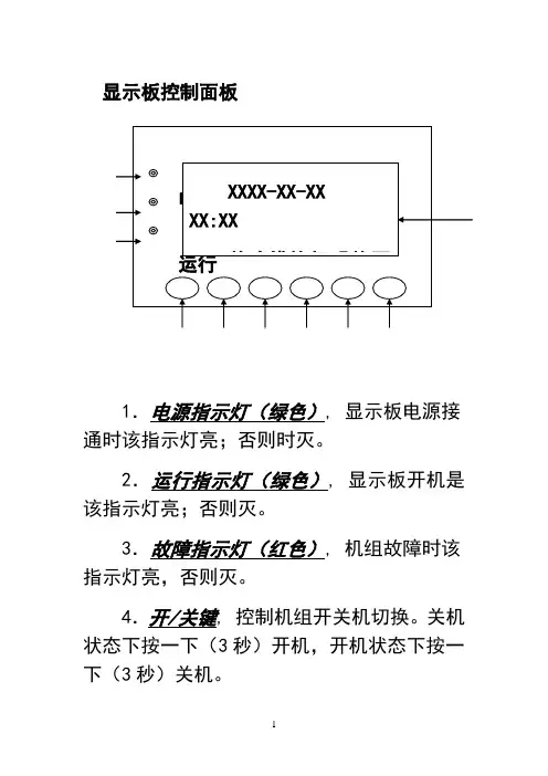
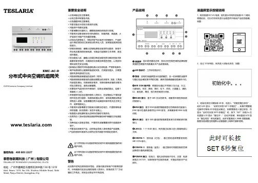
显示板控制面板1.电源指示灯(绿色), 显示板电源接通时该指示灯亮;否则时灭。
2.运行指示灯(绿色), 显示板开机是该指示灯亮;否则灭。
3.故障指示灯(红色), 机组故障时该指示灯亮,否则灭。
4.开/关键, 控制机组开关机切换。
关机状态下按一下(3秒)开机,开机状态下按一下(3秒)关机。
电源 运行 XXXX-XX-XX XX:XX 单冷模块机【热泵 4 5 615.复位键,按此键(3秒),屏幕满屏显示,故障显示清除,系统重新检测故障。
6.向上选择键,在菜单选择中,按此键光标向上或向左移动一项;在修改数据下,按此键增加数值。
7.向下选择键,在菜单选择中,按此键光标向下或向右移动一项;在修改数据下,按此键减小数值。
8.退出键, 按下此健,返回上级菜单。
9.确定键,在菜单选择中,按此键确认选择项,进入下级菜单;在修改参数下,按此键确认参数值并转移光标。
10.液晶显示器,信息显示区域。
显示板操作说明1. 机组的开/关非调试状态下机组的开关机,可以通过手动模式,也可通过定时模式。
手动模式优先于定时模式。
在调试状态下,手动和定时模式均无效。
●手动模式:1)、手动开机:在机组关机状态下,按开/关键3秒使机组启动,此时机组运行指示灯亮,压缩机延时启动后,手动开机过程结束;2)、手动关机:在机组开机状态下,按开/关键 3秒使机组关闭,此时运行指示灯熄灭。
停机后,压缩机立即停机,水泵会延时5分钟关闭。
手动关机过程结束。
●定时模式:机组上电或复位后,按手动模式进行开关机。
手动模式和定时模式的转换详见3.13启停模式设定。
在定时模式下手动和定时模式同时有效,当时间到达所设定的定时时间时,机组自动开启或关闭。
2. 默认主页菜单当控制器上电后,微电脑将做3秒钟的自动检测,显示板液晶显示器将显示如下:默认主页菜单内容随系统状态的变化而变化。
XX代表年月日小时和分钟,“【】”内的内容只显示其中的一个或不显示,分别表示系统的开关机状态、开机方式和联网模块数。
协议文档版本发布时间备注V1.02020.09.29前建立文件V1.12020.03.05增加风向、自动风速的控制和查询;增加主从机的查询;增加空调性能信息的查询V1.22020.03.30增加清爽、自动除湿、贴心睡眠三种模式MODBUS-RTU通讯协议应用说明表1网关通讯参数设置项目参数传输模式半双工波特率9600bps起始位1位数据位8位校验位偶校验(Even)停止位1位以上通讯规格参数也可以通过网关自带的WEB页面进行变更表2主要应用的功能码网关所用功能码作用0x03(读保存寄存器)用于读取空调的状态。
每次可读操作一个或多个寄存器(寄存器地址必须连续)。
每个寄存器保存一个空调的一个状态参数,根据寄存器读取的数量,可以一次读取一个空调的一个或多个参数(如开关、温度设定等),也可以将若干空调的全部参数一次读出。
0x06(写单个寄存器)用于写设定一个空调的一个参数每次只能写操作一个寄存器,每写操作一次,就会对一个空调的一个参数做出设定指令。
0x10(写多个寄存器)用于写设定多个空调的多个参数每次可写操作多个寄存器(寄存器地址必须连续)。
根据写寄存器的数量,可以一次写设定一个空调的一个参数或多个参数,也可以一次写多个空调的多个参数。
状态参数,包括:开关状态、温度设定值、模式设定状态、风速设定、房间温度和故障代码、是否为主机。
空调性能参数,包括:空调品牌、模式信息风速信息、设定温度信息、特殊性能信息表3状态保存寄存器地址与空调室内机地址的对应关系空调室内机地址状态参数保存寄存器地址0-00,1,2,3,4,50-16,7,8,9,10,110-212,13,14,15,16,17…………0-31186,187,188,189,190,1911-0192,193,194,195,196,1971-1198,199,200,201,202,2031-2204,205,206,207,208,209…………1-31378,379,380,381,382,383…………空调性能信息8000,8001,8002,8003,8004室内机状态参数保存寄存器起始地址为4000,每4个连续地址的寄存器保存1个室内机的控制指令,包括:开关指令、温度设定值指令、模式设定指令、风速设定指令、风向设定指令;表4控制指令寄存器地址与空调室内机地址的对应关系如下表空调室内机地址控制指令寄存器地址0-04000,4001,4002,40030-14004,4005,4006,40070-24008,4009,4010,4011…………0-314124,4125,4126,41271-04128,4129,4130,41311-14132,4133,4134,41351-24136,4137,4138,4139…………1-314252,4253,4254,4255…………表5查询空调状态所用的点位表(对应MODBUS功能码0x03)空调地址AA-BB 外部查询访问时的寄存器地址B15---B8B7B6B5B4B3B2B1B000-00D00000000000故障:1正常:0运行:1停止:0 D00010设定温度D00020设定模式0000制热送风除湿制冷D0003风向设定设定风速00000低速中速高速D0004B15-B9B8房间回风温度是否为主机D00050故障代码00-01D0006当前启停状态:0x01->开机;0x00->关机。

使用安装说明书中静压风管送风式空调器使用前请仔细阅读本说明书,并妥善保管更多使用指引,请扫描“扫码开启服务”二维码目录声明●本产品执行标准:GB/T 18836。
●本说明书仅作示例说明,产品及部件外观请以实物为准。
● 使用前请仔细阅读本说明书及电子说明书,否则可能会给本机造成损害或危及您或他人的人身 财产安全。
由于技术更新,致产品升级或变更,恕不另行通知。
电子说明书也会随技术创新进 行更新,请扫描二维码获取最新电子说明书。
● 阅读后请与发票一起妥善保管。
安全警示空调器主体构件配件清单遥控器使用说明清洁保养安装及维修注意事项环保清单安装简图室内机回风箱进风面板室内机排水管的安装技术参数检验运行使用条件常见现象及故障安装服务、售后服务保修卡安全警示产品简介使用说明清洁保养安装说明服务指南01030304050708131416171919192021封底查阅电子说明书方法● 请扫描说明书封底“扫码开启服务”二维码。
安全警示01提示本节记载了安全事项的重要内容,以防止对使用者及他人造成人身伤害或财产损失。
请在充分理解下面内容(标志、图标)的基础上阅读正文,并请务必遵守所记载的安全事项。
禁止用电源开关直接关闭空调器。
请勿用湿手操作空调器。
禁止用水直接冲淋空调器。
卸下或打开面板时,切勿触碰空调器的金属部位。
不得让身体长时间直接接触冷风或制冷过度。
不得踩踏在室内机、室外机上,或在其上放置物品,避免遮挡进、出风口。
切勿用于食品、精密仪器、贵重美术品的保存,切勿安装在船舶、车辆等特殊场所。
切勿在空调风直接吹到的地方使用燃烧器具,在密闭的房间内使用或与燃烧器具同时使用时,请经常打开窗户通风。
切勿在室内机下面放置其它电气产品、家具、贵重物品等。
禁止擅自更换电源线,或将电源线中途驳接,或与其它电器并联使用;如果电源软线损坏,为了避免危险,必须由制造商、其维修部或类似部门的专业人员更换。
表示【禁止】的内容禁止在空调器使用场所存放易燃易爆气体;不得使用与空调器本身所配制冷剂不同的其它制冷剂。
联系我们在线客服:https://www.xiaoyan.io/service 服务电话:400-920-2823电子邮件:******************上海小燕科技有限公司上海市浦东新区盛夏路666号E 幢502室1. 2.小燕室内机空调网关使用 ZigBee 无线通信协议,支持控制空调模式、温度、风速,实现智能控温、智能场景、绑定联动等功能。
产品介绍安装前请先将室内机断电,请勿带电操作。
打开空调内机检修口,将室内机网关置于吊顶上,注意安放位置远离内机,避免空调结露滴到网关上。
空调机网关不需供电,将室内机网关连接到内机线控端子处,各品牌连接方法如下表:将网关 P1/P2 连接线控端子 P1 P2不分正负将网关 P1/P2 连接线控端子 A B 不分正负将网关 P1/P2 连接线控端子 U3 U4 或A B 不分正负将网关 P1/P2 连接线控端子 X Y 不分正负安装说明-接线方式接线拨码完成后,给内机上电,网关开始自行搜索空调,搜索完毕后网关状态灯 STAT 由闪烁变为常亮,设备进入正常工作状态。
指示灯说明如果不保留原厂面板,请跳过此步骤。
原厂线控和室内机网关默认都作为主线控使用,如果要保留原厂线控,需将原厂线控或者室内机网关其中之一改为从线控才可避免冲突。
设置完成后需要给内机重新上电才能生效。
将室内机网关改为从线控方法:安装说明-与原厂面板共存温控面板使用(参考接线图1)需要将室内机网关的485的 AB 线连接到温控面板的485AB 线,建议面板单独供电,如需使用网关供电,此时网关的 VOUT+ VOUT- 可作为输出使用,最大向外输出 12V/40mA 。
空调线控端子(AIRCON P1 P2)用于第三方面板连接的485总线(485 A B )如果需要可以向面板供电 (VOUT + -)原厂线控可不接或按需配置安装说明-第三方温控面板将原厂面板改为从线控方法:安装说明-与原厂面板共存12345678大金日立东芝无无无无2根线2根线2根线2根线支持支持支持支持品牌接线方法接线极性接线数量原厂面板共存三菱重工将内机显示板的五芯线控延长线剪断 然后按照线序连接网关将三菱电机风管机专用接插件插到内机板上的 CN105 处将大金风管机专用接插件插到内机板上的S21 处将日立风管机专用接插件插到内机板上的CN2(线控器红)处将格力风管机专用接插件插到内机板 CN5(红色)处将网关 P1/P2 连接线控端子 P1 P2不分正负有有有有有无熄灭闪烁常亮未上电---供电正常4根线4根线4根线4根线4根线2根线支持支持不支持不支持不支持支持品牌接线方法接线极性接线数量原厂面板共存日立风管格力风管大金新风大金风管三菱电机美的C, E, H 系列原厂线控通过背面拨码开关进行设置,拨到从F 系列原厂线控通过长按取消按键进入菜单设置,选择主从设置,设置为从3Q 6Q 9Q 等面板直接并联,自动识别亲自无需设置8Q 面板不支持亲子共用,必须将原厂面板去掉86小面积背面拨码1拨到 0N 为从将网关 P1/P2 连接线控端子 P1 P2 不分正负翻盖面板通过背面 SW1 设置 拨到从菱耀室内机网关并未连接到线控上,与线控互不影响接触面板上电会提示是否使用之前设置,选择否,然后会再次提示选择为从品牌设置方法三菱重工三菱电机东芝日立大金将原厂面板改为从线控方法:安装说明-与原厂面板共存美的线控为单向传输,没有反馈,可以共用但不能同步不支持共用,必须将原厂面板去掉不支持共用,必须将原厂面板去掉不支持共用,必须将原厂面板去掉威能线控为单向传输,没有反馈,可以共用但不能同步品牌指示灯配网指示灯状态电源指示灯PWR网关状态灯STAT空调运转灯RUN空调模式灯MODE设置方法格力风管日立风管大金风管美的威能第三方显示面板线控网关室内机原厂线控器11234324搜索空调中设备异常空调关闭空调故障搜索完成空调开启红色制热模式蓝色制冷模式红蓝除湿模式正在连接附近的家庭中心送风模式---快速闪(每秒闪10下)连接家庭中心成功慢速闪(每2秒闪1下)连接家庭中心失败中速闪(每秒闪4下)官方微信恢复出厂设置参数规格质 保 卡1.2.3.4.启动小燕在家 APP, 登录进入;点击进入“添加设备”页面;接通网关电源,指示灯闪烁;约10秒后 APP 上显示找到新设备。
1、网关接通DC12V 电源,首先显示本网关的设备ID 二维码,根据此码,可以对本网关进行远程固件升级或产品信息查看,如图:2、经过10秒钟后,网关进入初始化状态,如图:3、初始化状态大概持续20秒,后进入“可触发复位状态”,此时LCD 显示:“此时可长按SET 5秒复位”,如果不需要复位操作可等待20秒后自动跳过,如果需要进入复位状态,在显示“此时可长按SET5秒复位”时,按下“SET”持续5s 左右直到LCD 显示“复位中...”后松开按键,等待直到LCD 显示“复位成功”即完成复位,此时可直接进入WEB 页面配置,配置完成或复位恢复默认设置重新上电即可重新使用。
液晶屏显示按键说明TESLARIA分布式中央空调机组网关EMC-AC-D©2018 teslaria Company Limited这个符号表示本设备附带的说明书中具有重要的操作和维护说明。
重要安全说明• 必须保留这些注意事项。
• 必须注意所有警告内容。
• 必须遵循所有注意事项。
• 不要在靠近水的地方使用本设备。
• 只能用干布擦拭设备。
• 不要堵塞任何通风口。
遵循制造商的说明进行安装。
• 不要将本设备安装在任何热源附近,如散热器、调温器、火炉或其它可能产生热量的装置。
•必须由合资格电工,按相关电气标准进行安装操作;产品的运行调试须由经过系统培训的专业人员,按照指定规则说明的进行。
•在模块使用前,请确认控制电源电压是否符合要求,使用不符合电压要求的控制电源,可能会引起模块工作异常,甚至损坏模块。
•在负载接入前,请确认负载功率或负载性质与模块的技术参数要求是否相符,负载线径与负载功率是否匹配,以免损坏模块或发生安全问题。
•接线前必须断开所有通道电源以及总线电源,严禁带电操作。
• 保护电源线防止被脚踩踏或被夹紧,尤其是在插头、方便插座和机身电源线引出处。
• 只能使用制造商指定的连接件 / 附件。
• 只能使用制造商指定的或随设备售出的手推车、支座、三角架、托架或支撑台。

目录一、系统介绍 -------------------------------------------------------------------- 2二、机组介绍 -------------------------------------------------------------------- 31.机组性能 ---------------------------------------------------------------------------------------- 3 2.机组外形示意图 ------------------------------------------------------------------------------- 4三、控制器操作说明 ----------------------------------------------------------- 6A.手操器显示功能------------------------------------------------------------------------------- 6 B.手操器按键功能 ----------------------------------------------------------------------------- 7 C.蜂鸣器------------------------------------------------------------------------------------------- 7 D.基本操作---------------------------------------------------------------------------------------- 7 E.故障代码表 ------------------------------------------------------------------------------------- 8四、日常操作与维护 ----------------------------------------------------------- 8五、常见故障及解决方法------------------------------------------------------ 9六、末端设备选型指导------------------------------------------------------- 10七、系统安装 ------------------------------------------------------------------ 101.机组安装 -------------------------------------------------------------------------------------- 10 2.机组接线 -------------------------------------------------------------------------------------- 12 3.末端设备安装 -------------------------------------------------------------------------------- 13 4.水管路连接 ----------------------------------------------------------------------------------- 13 5.冬季防冻注意事项 -------------------------------------------------------------------------- 14八、系统调试 ------------------------------------------------------------------ 151.空调系统冷冻水的充注 -------------------------------------------------------------------- 15 2.试运转前的检查 ----------------------------------------------------------------------------- 15 3.试运行 ----------------------------------------------------------------------------------------- 15九、随机附件使用说明------------------------------------------------------- 16尊敬的用户:欢迎您选用格力双系统户式(别墅)中央空调机组。
家用中央空调使用说明一、安装与调试在使用家用中央空调之前,首先要确保其安装和调试工作已经完成。
安装工作应由专业的安装人员进行,包括室内机和室外机的安装、管道连接、电气布线等。
安装完成后,需要进行调试,以确保系统运行正常。
调试时,需要检查空调的制冷、制热效果、风速、温度控制等功能是否正常。
同时,要检查空调系统是否有漏氟、漏水等问题。
如果发现问题,应及时联系安装人员进行处理。
二、开机与关机1、开机找到空调遥控器,确保电池电量充足。
按下遥控器上的“电源”按钮,启动空调。
选择运行模式,如制冷、制热、除湿、通风等。
一般来说,夏季选择制冷模式,冬季选择制热模式,潮湿的季节选择除湿模式,需要换气时选择通风模式。
设置温度。
根据您的需求,通过遥控器上的“温度+”和“温度”按钮来调整室内温度。
制冷时,建议温度设置在 25℃ 27℃之间;制热时,建议温度设置在 18℃ 22℃之间。
调整风速。
可以选择自动风速、低风速、中风速、高风速等不同的风速档位。
如果需要定时开机或关机,可以通过遥控器上的“定时”功能进行设置。
2、关机按下遥控器上的“电源”按钮,关闭空调。
如果长时间不使用空调,建议拔掉电源插头,以节省能源并确保安全。
三、温度调节合理的温度设置不仅能提高舒适度,还能节省能源。
在制冷模式下,温度设置过低不仅会增加耗电量,还可能导致室内外温差过大,引起身体不适。
在制热模式下,温度设置过高也会造成能源浪费,并使室内空气过于干燥。
此外,不同的房间和使用场景可能需要不同的温度设置。
例如,卧室的温度可以设置得稍高一些,以保证良好的睡眠环境;客厅等活动频繁的区域,温度可以根据个人感受进行适当调整。
四、风速调节风速的调节可以影响室内空气的循环速度和制冷、制热效果。
在刚开机时,可以选择高风速,以快速达到设定温度。
当室内温度接近设定温度时,可以将风速调整为低风速或自动风速,以保持舒适的室内环境。
如果房间较大,可以适当提高风速,以使室内空气均匀分布;如果房间较小,可以选择较低的风速,避免吹风感过强。
格力空调控制面板说明书一、产品概述:二、外观和按键介绍:1.面板外观:控制面板采用高质量的塑料外壳,外观简洁大方,配有LED显示屏,显示室内温度、湿度和时间等信息。
2.按键:面板上有多个功能按钮,包括电源开/关按钮、模式选择按钮、温度调节按钮、风速控制按钮、节能模式按钮等。
三、功能和操作说明:1.电源开/关:按下电源开/关按钮,可以将空调的电源打开或关闭。
2.模式选择:通过模式选择按钮,可以调节空调的运行模式,包括制冷、制热、除湿、送风等模式,满足不同季节和需求下的使用要求。
3.温度调节:使用温度调节按钮,可以调节空调设定的目标温度,按上箭头提高温度,按下箭头降低温度。
4.风速控制:通过风速控制按钮,可以调节空调送风的速度,包括高速、中速、低速和自动等档位。
5.节能模式:空调面板上配有节能模式按钮,可以通过按下该按钮来开启或关闭节能模式,在节能模式下,空调会自动调整工作模式和温度,以降低能耗。
四、自动调温和定时功能:1.自动调温:空调面板上的自动调温功能,可以根据室内环境变化,自动调节空调的运行模式和温度,保持室内舒适。
2.定时功能:空调面板配备定时功能,用户可以设置开机时间和关机时间,让空调在指定的时间自动开关机,方便用户合理安排空调的使用时间。
五、故障排除:在使用过程中,可能会遇到一些故障,如空调无法开启、显示屏不亮等问题,以下是一些常见故障的解决办法:六、注意事项:1.本产品需由专业人士安装和维护,请勿私自拆卸或修理。
2.在使用和操作过程中,请确保面板干燥、无污渍,避免液体进入面板造成损坏。
3.使用空调时,请确保通风良好,室内空气质量良好,避免因空调长时间使用而造成不适。
4.定期对空调进行清洁和维护,以保持其良好的工作状态。
所有空调1个硬件室外机网关用户手册版本:V2.0青岛中弘智能物联有限公司目录第一章产品概述 (3)1.1、产品简介 (3)1.2、支持协议及规格说明 (3)第二章产品安装 (5)2.1、外形尺寸及安装环境 (5)2.2、LED指示灯说明 (6)2.3、接线方式及注意事项 (7)第三章硬件配置 (8)3.1、硬件配置准备 (8)3.2、产品接线端口选择及通讯匹配 (8)3.3、液晶屏显示说明 (10)3.4、按键指示说明 (11)第四章蓝牙配置说明 (12)4.1、网关页面 (13)4.2、空调页面 (14)4.3、升级页面 (14)4.4、调试页面 (15)第一章产品概述1.1、产品简介感谢您购买多功能空调网关,本产品可将多联式空调连接至智能家居集中控制系统或BMS系统。
可提供的接口方式为RS485、KNX或第三方无线模组。
目前可以支持大金、日立、东芝、三菱电机、海信、海尔、松下、约克、三菱重工、美的、LG、奥克斯、博世、格力、天加、三星、志高、特灵、开利、麦克维尔等品牌的多联机空调系统。
具体机型信息详见我司网站及微信公众号(手册末页)。
安装使用产品前,请先仔细阅读本手册,以便全面了解本产品的所有功能。
1.2、支持协议及规格说明1.2.1支持如下协议:MODBUS-RTU/VRV485(中弘自有协议)KNX(需要该协议采购时候提前说明)基于RS485的其他厂家自定义协议(针对新风、地暖、智能家居系统)TCP/UDP支持第三方无线模组接入(ZigBee、BLE、WIFI)规格及说明表1电气参数项目名称规格参数产品尺寸106*96*58mm输入电源DC12V消耗功率 2.0W以下工作温度-20-80℃,90%RH配置升级蓝牙+微信小程序安装方式导轨或摆放智能化设备接口ZigBee/BLE/WIFI/RS485等表2RS485端口出厂默认通讯规格(以下参数也可以通过小程序页面变更)项目参数传输模式半双工波特率9600bps起始位1位数据位8位校验位偶校验(Even)停止位1位第二章产品安装2.1、外形尺寸及安装环境本产品需要安装在户内,采用导轨安装在弱电控制箱内。
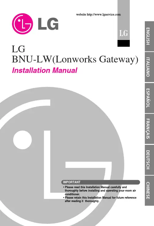
LGBNU-LW(Lonworks Gateway) Installation Manual• Please read this Installation Manual carefully andthoroughly before installing and operating your room airconditioner.• Please retain this Installation Manual for future referenceafter reading it thoroughly.Safety Precautions (3)Overall system diagram (7)External wiring diagram (8)How to set the address for the central controller of the indoor unitconnected to BNU-LW (Lonworks Gateway) (8)Communication line specification (9)Name of each part (10)Installation order (11)BNU-LW wiring order (12)Air conditioner/ventilation function table (13)Air conditioner indoor unit function (13)Ventilation indoor unit function (14)BNU-LW remote diagnosis function (15)Setting method (15)Configuration (16)Setting the indoor unit address (18)Setting the indoor unit address (18)Interfacing with simple central controller (19)Appendix (20)A/C Objects (20)Air conditioner control/monitoring point (21)Ventilation control/monitoring point (22)Network variables (23)2Lonworks GatewaySafety PrecautionsInstallation Manual3Safety Precautions4Lonworks GatewaySafety PrecautionsInstallation Manual5Safety Precautions6Lonworks GatewayOverall system diagramInstallation Manual7controllerA/C485 communicationExternal wiring diagram8Lonworks GatewayRI485Central controller address(2.0)Central controller address(2.4)(2.1)(2.2)(2.3)(2.5)(2.6)(2.7)Air conditioner RI485External wiring diagramInstallation Manual91. RS-485 communication line specification: 0.75mm 2or above 2C shield, product to product: 200M,total length: 1km2. FT-10 communication line: Refer to the following table.* Nod to node distance (max): 250m, maximum distance: 450m* AWG: American Wire GaugeCable TypeLine thickness (AWG)Diameter TIA 568A Category 5 cable 240.5mm Belden 88471 (PVC jacket) or 161.3mm equivalent cableBelden 85102(Tefzel jacket) or 16 1.3mm equal cable Level IV cable 220.65mm JY(st)Y 2x2x0.820.40.8mmName of each part10Lonworks GatewayInstallation order5. When you press the service switch after connecting to the Lonworks system, the service LED is turned on and the neuron ID is automatically transmitted to the Lonworks system.6. Check whether the service LED is in normal condition (OFF condition) within 10 minutes. If the service LED is in normal condition, the installation has been done normally.BNU-LW wiring orderFire detection sensor (Use DC 12V or below)Centralcontroller PI485 VOCGNDCD10VGNDBUS_ABUS_B LG supply[Wiring sequence]1. Connect 485 communication lineAir conditioner/ventilation function tableO O O O O O BMSBNU-LWAir conditionerBMSBNU-LWAir conditionerAir conditioner/ventilation function tableO O O BMSBNU-LWVentilationBMSBNU-LWVentilationBNU-LW remote diagnosis functionBNU-LW remote diagnosis function"A""B"BNU-LW remote diagnosis functionWhen you would like to change the IP and Gateway, Subnet maskSetting the indoor unit addressbutton pressed, press the Reset button .2. By using the temperature adjustment button, set the indoor unit address.Setting range: 00~FF3. After setting the address, press the ON/OFF button toward the indoorunit 1 time.4. The indoor unit will display the set address to complete the addressInterfacing with simple central controllerHow to set PI-485How to set PI-485• BNU-LW uses LGAP communication protocol.You can set the DIP S/W No. 1 and No. 4 of PI-485 ON.AppendixOn/Off status monitoringMode status monitoringFan level status monitoringAppendixO N /O F F (s e t t i n g )S N V T _s w i t c h n v i O n O f f _n n i n p u t S t o pO p e r a t i o nO N /O F F (s t a t u s )S N V T _s w i t c h n v o O n O f f _n no u t p u t S t o p O p e r a t i o n L o c k (s e t t i n g )S N V T _s w i t c h n v i L o c k _n ni n p u t C a n c e l S e t t i n g L o c k (s t a t u s )S N V T _s w i t c h n v o L o c k _n no u t p u t C a n c e l S e t t i n gO p e r a t i o n M o d e (s e t t i n g )S N V T _h v a c _m o d e n v i H e a t C o o l _n ni n p u tA u t o H e a t i n g C o o l i n g F a nD r yO p e r a t i o n M o d e (s t a t u s )S N V T _h v a c _m o d e n v i H e a t C o o l _n no u t p u tA u t o H e a t i n g C o o l i n g F a n D r yS w i n g (s e t t i n g )S N V T _s w i t c h n v i S w i n g _n ni n p u tC a n c e l S e t t i n g S w i n g (s t a t u s )S N V T _s w i t c h n v o S w i n g _n no u t p u tC a n c e l S e t t i n gF a n s p e e d (s e t t i n g )S N V T _s w i t c h n v i F a n S p e e d C m d _n ni n p u tL o wM e dH i g hA u t o S u p e r L o wF a n s p e e d (s t a t u s )S N V T _s w i t c h n v o F a n S p e e d _n no u t p u tL o w M e d H i g h A u t o S u p e r L o wS e t R o o m T e m p e r a t u r e S N V T _t e m p _p n v i S e t P o i n t C m d _n ni n p u t°CS e t R o o m T e m p e r a t u r e S N V T _t e m p _p n v o S e t P o i n t _n no u t p u t°CR o o m T e m p e r a t u r e S N V T _t e m p _p n v o S p a c e T e m p _n no u t p u t°CE r r o r C o d e S N V T _h v a c _s t a t u s n v o U n i t S t a t u s _n no u t p u tn o e r r o r R e f e r t o t h e L G A i r C o n d i t i o n e r E r r o r C o d e .t N a m eO b j e c t T y p e U n i t c o d e 0c o d e 1c o d e 2c o d e 3c o d e 4c o d e 5c o d e 9c o d e 14O b j e c t N a m e (n n : A i r c o n d i t i o n e r a n d v e n t i l a t i o n g r o u p /i n d o o r u n i t a d d r e s s )AppendixO N /O F F (s e t t i n g )S N V T _s w i t c h n v i O n O f f _n ni n p u tS t o pO p e r a t i o n O N /O F F (s t a t u s )S N V T _s w i t c h n v o O n O f f _n no u t p u tS t o pO p e r a t i o nL o c k (s e t t i n g )S N V T _s w i t c h n v i L o c k _n ni n p u tC a n c e lS e t t i n gL o c k (s t a t u s )S N V T _s w i t c h n v o L o c k _n no u t p u tC a n c e lS e t t i n gO p e r a t i o n M o d e (s e t t i n g )S N V T _h v a c _m o d e n v i H e a t C o o l _n ni n p u tA u t oH e a t e x c h a n g eN o r m a lO p e r a t i o n M o d e (s t a t u s )S N V T _h v a c _m o d e n v i H e a t C o o l _n no u t p u tA u t o H e a t e x c h a n g eN o r m a lF a n s p e e d (s e t t i n g )S N V T _s w i t c h n v i F a n S p e e d C m d _n ni n p u tL o wH i g h V e r y h i g hF a n s p e e d (s t a t u s )S N V T _s w i t c h n v o F a n S p e e d _n no u t p u tL o wH i g h V e r y h i g hE r r o r C o d e S N V T _h v a c _s t a t u s n v o U n i t S t a t u s _n no u t p u tR e f e r t o t h e L G A i r C o n d i t i o n e r E r r o r C o d e .U s e r M o d e (s e t t i n g )S N V T _c o u n t n v i U s e r _n no u t p u tQ u i c k P o w e r s a v eh e a tU s e r M o d e (s t a t u s )S N V T _c o u n t n v o U s e r _n no u t p u tQ u i c k P o w e r s a v eh e a tt N a m eO b j e c t T y p eU n i tc ode 0c ode 1c o d e 2c o d e 3c o d e 5c o d e 9O b j e c t N a m e (n n : A i r c o n d i t i o n e r a n d v e n t i l a t i o n g r o u p /i n d o o r u n i t a d d r e s s )AppendixAppendixAppendixAppendixAppendixMemo。
目录第一章产品篇……………………………………………………………………1 产品种类…………………………………………………………………………………2 产品命名规则……………………………………………………………………………3 产品特点…………………………………………………………………………………4 产品技术参数表…………………………………………………………………………5 产品性能修正……………………………………………………………………………6 产品工作原理……………………………………………………………………………第二章控制篇……………………………………………………………………1 机组控制…………………………………………………………………………………2 控制功能…………………………………………………………………………………第三章安装篇……………………………………………………………………1 安装注意事项……………………………………………………………………………2 安装流程…………………………………………………………………………………3 机组安装要求……………………………………………………………………………4 配管………………………………………………………………………………………5 电气安装…………………………………………………………………………………第四章维修篇……………………………………………………………………1 机组故障一览表…………………………………………………………………………2 典型故障排查……………………………………………………………………………3 案例分析…………………………………………………………………………………4 机组配电…………………………………………………………………………………5 机组部件及拆装…………………………………………………………………………6 爆炸图及零部件清单……………………………………………………………………第一章产品篇1.产品种类1.1 GMV室外机1.2 GMV室内机◆GMV多联室内机组-H系列(R22)2.2kW~4kW 4.5kW~8kW 9kW~14kW普通静压风管机GMV(L)-R22P/HGMV(L)-R25P/HGMV(L)-R28P/HGMV(L)-R32P/HGMV(L)-R36P/HGMV(L)-R40P/HGMV(L)-R45P/HGMV(L)-R50P/HGMV(L)-R56P/HGMV(L)-R63P/HGMV(L)-R71P/HGMV(L)-R80P/HGMV(L)-R90P/H(S)GMV(L)-R100P/H(S)GMV(L)-R112P/H(S)GMV(L)-R125P/H(S)GMV(L)-R140P/H(S)超薄风管机GMV(L)-R22P/HLGMV(L)-R25P/HLGMV(L)-R28P/HLGMV(L)-R32P/HLGMV(L)-R36P/HLGMV(L)-R40P/HLGMV(L)-R45P/ HLGMV(L)-R50P/HLGMV(L)-R56P/HLGMV(L)-R63P/HLGMV(L)-R71P/ HL四面出风天井机GMV(L)-R28T/HGMV(L)-R36T/HGMV(L)-R45T/HGMV(L)-R50T/HGMV(L)-R56T/HGMV(L)-R63T/HGMV(L)-R71T/HGMV(L)-R80T/HGMV(L)-R90T/H(S)GMV(L)-R100T/H(S)GMV(L)-R112T/H(S)GMV(L)-R125T/H(S)单面出风天井机GMV(L)-R22Td/H GMV(L)-R28Td/H GMV(L)-R36Td/H挂壁机GMV(L)-R22G/HGMV(L)-R28G/HGMV(L)-R36G/H挂壁机GMV(L)-R45G/HGMV(L)-R50G/H◆GMV多联室内机组-R410A系列2.产品命名规则2.1 室外机命名规则GMV/W 补充代号型式代号设计序号室外机代号功能特征气候类型制冷量*电源种类补充制冷剂种类产品代号室外机型号含义如下表:标准主型号含义产品 代号气候类型型式代号功能特征制冷量室外机 代号* 补充代号:压缩机(或室外机)数量表示方法GMVT1-省略 T2-低温 气候 T3-高温 气候热泵型 省略 L-单冷型R-数码多联 P-交流变频多联 Re-低温热泵数码多联 Pd-直流变频多联名义制冷量×102 (W )W用数字表示,单压缩机省略;型号示例:GMV -R100W/H :表示名义制冷量为10kW 的H 系列数码多联热泵型空调室外机。
成都百微电子开发有限公司智能空调网关说明书HV352版本号:V1.0一、产品介绍HV352智能空调网关适用于多联式空调的控制,通过本产品,将空调系统连接到百微智能家居系统中,并实现控制。
目前本产品可以支持大金、日立、东芝、三菱电机、海信、海尔、松下、约克、三菱重工、美的、LG、奥克斯、博世、格力、天加、三星、志高、特灵、开利、麦克维尔等品牌的多联机空调系统。
单个空调网关最多可以接4套室外机,64个室内机。
同时本产品支持如下协议:◆RS485(针对新风、地暖、智能家居系统)◆Zigbee产品外观图二、产品安装2.1产品接线图单系统接线图多系统接线图安装注意事项:1.产品额定输入电压为DC12V,安装时请正确区分接口及正负极;2.空调室内机与室外机的通讯线由空调施工方负责,与空调室内、外机之间的制冷剂铜管一样,它属于空调系统的一部分,相关接线工作不由我司负责;3.本机需要安装在户内,可以安装在智能家居控制箱或者其附近。
接线注意事项:本机通过2芯线连接到空调系统室外机上,进而与该空调系统内所有的室内机通讯,实施监控。
从空调室外机到本机的屏蔽双绞线要求线径1.0或者1.5以上,可由空调施工方预留或后期增设。
本机与弱电集成系统之间的通讯也采用双绞线或网线实现,该通讯线的参数要求及施工细节请根据模块与弱电集成系统之间的位置确定。
所有的信号线电缆请不要与电源线以及其它的信号线并排走线,可能会引起由于干扰而产生误动作。
如果要并排走线的话,请保持和空调通讯的接线距离15cm,和其他接线距离30cm以上,或者将电缆接进铁制保护管并将保护管的一端接地。
机箱必须进行D种接地。
错误地将电源线连接到信号端子的情况下,保险丝会烧断以保护印刷电路板。
这个时候,请联系厂家,严禁私自拆卸维修。
否则厂家不支持售后。
接线操作的注意事项:应按要求选择线材,并确保线路安全且安装牢靠,同时要求无外力影响端子和线路;安装本设备之前请仔细阅读安全注意事项,并由专业人员进行安装;不同控制方式的输入端子接线端子不同。
1 操作说明6.1 开关机按“”键,启动空调。
再次按“”键,停止空调的运行。
开、关机界面如下图所示。
图6.1 开机界面图6.2 关机界面线控器XC70-24/H6.2 模式设置开机状态下,每一次按“模式”键,模式按如下顺序循环进行切换:或图6.3 模式切换注意!①不同系列的机型,支持的模式不同,线控器根据室内机机型自动选择模式设置范围;②多联机只有主从模式下的主内机才能设定自动模式;③自动模式时,如果室内机运行自动制冷,“”和“”亮,如果室内机运行自动制热,“”和“”亮。
6.3 温度设置开机状态下按“+”或“-”键,设定温度将以0.5℃/1℃(具体以P87参数设置为准)为单位增加或减少;长按时,每0.3秒温度以0.5℃/1℃为单位增加或减少。
线控器XC70-24/H 自动、制冷、送风、制热、地暖、3D供暖和供暖模式下,温度设定范围为:16℃~30℃。
除湿模式下,默认控制方式为“温度控制”,温度设定范围为12℃,16℃~30℃。
除湿模式下,当温度为16℃时,连续按两次“-”键可减到12℃(当制冷节能功能开启时,除湿温度不可调至12℃,范围为“节能温度下限值”~30℃)。
除湿模式控制方式为“湿度控制”时,按“+”或“-”键以5%为间隔调节设定湿度,可设范围是45%~75%,默认65%。
除湿模式湿度控制方式只有带有该功能的机组才能设置,设置方法详见5.2.3参数设置。
注意!①部分机型在自动模式下,不能通过“+”或“-”键调节设定温度。
②开启外出功能后,不能通过“+”或“-”键调节设定温度。
③线控器接新风室内机时,会显示新风室内机代码“FAP”,如下图所示,设定温度值不显示,不可以通过“+”或“-”键设定温度,只能在参数设置中设定制冷或制热出风温度。
线控器XC70-24/H图6.4 FAP状态6.4 风速设置开机状态下,按“风速”键,风速按如下顺序循环进行切换:图6.5 风速切换开启强劲风功能:开机状态下,按“功能”键,切换至强劲风功能,强劲风图标“”闪烁,按“睡眠/确认”键开启强劲风。
Technical DataCENTERLINE 2500 Motor Control Centers with EtherNet/IP NetworkCENTERLINE 2500 Motor Control Centers with EtherNet/IP Technical DataTable of ContentsReference Materials. . . . . . . . . . . . . . . . . . . . . . . . . . . . . . . . . . . . . . . . . . . . . . . . . . . 2Overview. . . . . . . . . . . . . . . . . . . . . . . . . . . . . . . . . . . . . . . . . . . . . . . . . . . . . . . . . . . . 3EtherNet/IP Network Overview . . . . . . . . . . . . . . . . . . . . . . . . . . . . . . . . . . . . . . . . . . 3EtherNet/IP Network in MCCs. . . . . . . . . . . . . . . . . . . . . . . . . . . . . . . . . . . . . . . . . . . 3System Architecture. . . . . . . . . . . . . . . . . . . . . . . . . . . . . . . . . . . . . . . . . . . . . . . . . . . 3Adding a Motor Control Center Unit to an EtherNet/IP System . . . . . . . . . . . . . . . . . 7Ethernet Power Suppy . . . . . . . . . . . . . . . . . . . . . . . . . . . . . . . . . . . . . . . . . . . . . . . . . 7System Design Installation Checklist. . . . . . . . . . . . . . . . . . . . . . . . . . . . . . . . . . . . . . 8EtherNet/IP Software Installation Checklist . . . . . . . . . . . . . . . . . . . . . . . . . . . . . . . . 9How to Find Electronic Data Sheets (EDS). . . . . . . . . . . . . . . . . . . . . . . . . . . . . . . . . . 9Reference MaterialsFor additional CENTERLINE 2100 Motor Control Center data and general information, refer to the following publications and websites.Title Publication Available Online at…CENTERLINE 2100 Motor Control Centers Product Profile2100-PP020/literature Integrated Intelligence within an MCC—IntelliCENTER Product Profile MCC-PP001IntelliCENTER Software User Manual MCC-UM001Integrated, Intelligent Motor Control Centers White Paper2100-WP001Joining and Splicing Vertical Sections Installation Instructions2100-IN010EtherNet/IP Performance Application Solution ENET-AP001EtherNet/IP Modules in Logix 5000 Control Systems User Manual ENET-UM001NetLinx Selection Guide NETS-SG001Ethernet: Technology Enabler for Network Convergence White Paper NETS-WP005IntelliCENTER Technology Website /intellicenterMotor Control Centers (MCC)/mccElectronic Publications /literature EtherNet/IP Network (Allen-Bradley)/networksEtherNet/IP Capacity Tool /solutions/integratedarchitecture/resources3.html Electronic Data Sheets (EDS) files /resources/eds/EtherNet/IP Media Planning and Installation Manual This manual is available from the OpenDeviceNet Vendor Association (ODVA) at2Publication 2500-TD003A-EN-PCENTERLINE 2500 Motor Control Centers with EtherNet/IP Technical DataPublication 2500-TD003A-EN-P 3OverviewThis document describes cable system construction and components associated with an EtherNet/IP network that is factory installed in CENTERLINE 2500 and IntelliCENTER motor control centers (MCCs).EtherNet/IP Network OverviewThe EtherNet/IP network offers a full suite of control, configuration, and data collection services by layering the Common Industrial Protocol over the standard protocols used by the Internet (TCP/IP and UDP). The EtherNet/IP network uses TCP/IP for general messaging and information exchange services, and UDP/IP for I/O messaging services for control applications. This combination of well-accepted standards provides the functionality required to support both information data exchange as well as control applications.Another key feature of the EtherNet/IP network is that it uses commercial, off-the-shelf Ethernet components and physical media. This provides a cost-effective plant floor solution by using a familiar and well-understoodinfrastructure.The EtherNet/IP network is most often used in these types of configurations:•As an economical solution for connecting many computers•As the best choice when you want to connect many devices•As the standard network for connectivity to enterprise systems•As the least expensive HMI option when used with PanelView Plus terminal•In a star topology when nodes are grouped closely togetherEtherNet/IP Network in MCCsThe EtherNet/IP network integrates with current IT networks. This document details the applications of the EtherNet/IP network in MCCs, including cable system construction and common EtherNet/IP components.System ArchitectureWhen designing EtherNet/IP systems, it is necessary to consider the following factors:•Connection count•Cable type and lengthsATTENTION: Before performing any service or maintenance activities on MCC columns, disconnect all power sources.Follow local codes and guidelines in addition to the requirements of EN 50110.CENTERLINE 2500 Motor Control Centers with EtherNet/IP Technical Data4Publication 2500-TD003A-EN-PConnection CountThe EtherNet/IP network can accommodate a vast number of nodes. The EtherNet/IP network does not have a specific maximum number of nodes like other fieldbus networks. The limit is based on the number of connections the EtherNet/IP scanner can make.The number of connections used by each node varies. To estimate the number of connections a network would use, visit /solutions/integratedarchitecture/resources3.html for our EtherNet/IP Capacity Tool.Cable Length LimitationsThe EtherNet/IP network uses fiber or copper twisted-pair wiring. The maximum length of copper twisted-pair wiring is 100 m between devices. There is no cumulative length for the entire network. Fiber cable length varies by design of the cable. Inside the MCC, all cables are copper twisted-pair.Cable Routing Figure 1. Typical Single MCC ColumnIMPORTANT The 100 m maximum length has to account for Ethernet cable inside the column. There is already up to three meters of cable from the Grace port on the power supply moduleto the Ethernet switch. This cable length is added to the distance of the length between the Grace port and the externally connected device.Out to section on right.Power BusCENTERLINE 2500 Motor Control Centers with EtherNet/IP Technical DataEach EtherNet/IP network has one or two Stratix 6000 switches that are always mounted in the top horizontal wireway in the standard configuration. The number of switches depends on the number of units in the column. Cables connected to the switch are then routed to EtherNet/IP connections in the network wireway. Up to 12 EtherNet/IP ports can be provided in the network wireway.In a standard MCC column, the vertical network wireway has EtherNet/IP connections equal to the number of units, up to 12, for that column. Devices that require 24V DC to power up will have it supplied via the control plug via pins B4 and B5. These pins are reserved for the 24V DC power and should not be used for other reasons.Connection to the EtherNet/IP network and the control plug is made when a unit is in the Connected or Test position.The addition or removal of a unit from the EtherNet/IP system does not interrupt the operation of other units in the system.Figure 2. Typical Two-column Shipping BlockDetermining Cable LengthsTo help determine cable lengths for your application, each MCC is shipped with documentation identifying the cable length used within the MCC.Publication 2500-TD003A-EN-P5CENTERLINE 2500 Motor Control Centers with EtherNet/IP Technical Data6Publication 2500-TD003A-EN-PMCC Cable TypesThe CENTERLINE 2500 MCCs use a high voltage 600V Ethernet cable designed to perform above TIA 568-B.2 and ODVA Ethernet standards. These cables have the following features:•Foil and braided shield, PVC, eight conductor (four pair)•600V PVC cable designed to support high voltage applications•On-machine rated cable for use in a cable tray shared with high voltage power cables•RJ45 insulation displacement connector available for field terminations•Wide thermal operating range of -20…80 °CFigure 3. EtherNet/IP Cable Pin-outATTENTION: Do not apply high voltage to any installed EtherNet/IP cable system or its connectors.Cable Specifications CertificationsUL and cUL Listed Outside diameter0.32 ± 0.015 in. (8.13 ± 0.38 mm)Operating temperature-20…80 °C (-4…176 °F)Cable Rating UL, cUL TYPE CMG; UL PLTC or UL AWM 257080C 600V, TIA 568B 1 - White/Orange TxData +2 - Orange TxData -3 - White/GreenRecv Data +4 - BlueUnused 5 - White/BlueUnused 6 - GreenRecv Data -7 - White/BrownUnused 8 - Brown UnusedCENTERLINE 2500 Motor Control Centers with EtherNet/IP Technical DataPublication 2500-TD003A-EN-P 7Adding a Motor Control Center Unit to an EtherNet/IP SystemUse this section to add Bulletin 2500 units to an EtherNet/IP MCC. Each EtherNet/IP component is factory wired within the unit and has a communication cable that plugs into the device on one end and generally into a vertical wireway EtherNet/IP port on the other end.Ethernet Power SuppyA power supply unit that meets EtherNet/IP requirements can be supplied with the MCC. A cable connects the output of the power supply to pins C3 and C4 of the control plug in the network wireway. This cable is already connected when the power supply unit ships installed in the MCC. Redundant configurations are also available.Connecting Power Supplies—Remote or in the MCC Line-upConnecting power supplies according to these guidelines will minimize voltage drops in the EtherNet/IP system and ensure proper supply voltage to system devices. Refer to the Converged Plantwide Ethernet Design andImplementation Guide , ENET-TD001, for detailed connecting instructions.Network Power Supply and the Protective Earth CircuitThe EtherNet/IP network is grounded at the various components via the component ground; therefore, no further grounding needs to be connected to the Ethernet cables.No. of Conductors Jacket Material Cable Type Cable Rating Cat. No.(1)(1)Replace -2 (2 m) with -5 (5 m), or -10 (10 m) for additional standard cable lengths.8Teal 600V PVCFoil and braided shield (UL) CMX, CMR; c(UL) CMG; (UL) PLTC or AWM 2570 80 °C 600V; TIA-568-B 1585J-M8HBJM-2Red 600V PVC 1585J-M8EBJM-2IMPORTANT Many EtherNet/IP components require 24V DC power source to operate. The power supply must be EtherNet/IP compatible as specified in the ODVA requirements.Power supplies that do not satisfy both points listed above can result in damage to theEtherNet/IP signal and components, as well as failure to comply with local codes andinspection.IMPORTANT It should be noted that the 24V DC common in the power supply bucket should not be connected to the PE. Doing so violates the grounding in the various EtherNet/IPcomponents.CENTERLINE 2500 Motor Control Centers with EtherNet/IP Technical DataConnecting Two Power SuppliesAn additional 24V DC Class 1 power supply must be installed for MCC line-ups with approximately 14 columns. When using two supplies, there should be a break between the two 24V DC networks. Locate the appropriate break for the two networks and ensure the terminal blocks are not connected between these two columns.Figure 4. Connecting Two Power SuppliesPosition each power supply to ensure that it feeds a maximum of seven columns to the left or right (refer to the sample line-up below).System Design Installation ChecklistWhen installing an EtherNet/IP MCC, use the following checklist before applying power to the network:•Ensure only one power supply is connected for each 14 sections of MCC.•Verify that the power supply for the system is 24V DC.•Ensure that the PE is connected.•Inspect connections for loose wires, opens, and shorts.8Publication 2500-TD003A-EN-PCENTERLINE 2500 Motor Control Centers with EtherNet/IP Technical DataPublication 2500-TD003A-EN-P 9EtherNet/IP Software Installation ChecklistThe following steps, along with references for more information, are provided to assist with the EtherNet/IP software installation process.1.Install the communication card in your personal computer.2.Load the Windows hardware drivers for the communication card.3.Load RSLinx software.4.Configure the RSLinx driver.Within the RSWho function, make sure no unrecognized devices (the ‘?’ symbols) appear for any devices. If an unrecognized device appears, load the electronic data sheet (EDS) file.Refer to How to Find Electronic Data Sheets (EDS) on page -9 for additional details.e the device web pages or RSLogix 5000 software to program and configure devices (for example, full load current, acceleration rate).6.Write the PLC program.7.If IntelliCENTER software is provided, load per the IntelliCENTER Software User Guide,publication MCC-UM001.How to Find Electronic Data Sheets (EDS)After installing IntelliCENTER software, an electronic data sheet (EDS) file must be registered for each unique device in the MCC. This section describes the procedure to perform this task.Definition of EDS FilesEDS files are simple text files used by network configuration tools—such as RSNetWorx, RSLogix 5000, andIntelliCENTER software—to help identify products and easily commission them on a network. EDS files describe a product’s device type, revision, and configurable parameters on an EtherNet/IP network.Necessary EDS FilesThe IntelliCENTER data CD contains a directory (<cdrom>:\<order>\<item>\EDS) of EDS files necessary for the devices in your IntelliCENTER MCC. The EDS files are automatically registered by the installation program.For EtherNet/IP MCCs, an ‘EDS file’ CD is provided. This CD contains EDS files for all EtherNet/IP products found in MCCs.IMPORTANT Do not leave the RSWho constantly browsing. Close the RSWho screen or disable Autobrowse.CENTERLINE 2500 Motor Control Centers with EtherNet/IP Technical DataInstalling EDS FilesEDS files are installed with a program from Rockwell Software called ‘RSHWare.exe’. This program is included on the IntelliCENTER data CD (in the same directory as the EDS files).Follow these steps to install EDS files:1.Run the program RSHW are.exe.2.Click Add/Remove.3.Select Register an EDS file and click Next.4.Select Register a directory of EDS files.5.Browse to the EDS directory on the data CD.6.Click Next.The Installer will display the test results.7.Click Next to continue.The Installer will allow you to change the graphic image for each device.8.Click Next to continue.The Installer will display the final task summary.9.Click Next to continue.10.Click Finish when completed.Finding EDS Files for Other DevicesEDS files can be obtained at /resources/eds/.Uploading EDS Files from the DeviceRSNetWorx for EtherNet/IP software can be used to upload an EDS file directly from a device. If an EDS file cannot be found by other methods, refer to the RSNetWorx help file for steps to upload an EDS file.10Publication 2500-TD003A-EN-PCENTERLINE 2500 Motor Control Centers with EtherNet/IP Technical DataNOTES:Publication 2500-TD003A-EN-P11Rockwell Otomasyon Ticaret A.Ş., Kar Plaza İş Merkezi E Blok Kat:6 34752 İçerenköy, İstanbul, Tel: +90 (216) 5698400Publication 2500-TD003A-EN-P - March 2011 Copyright © 2011 Rockwell Automation, Inc. All rights reserved. Printed in the U.S.A.Rockwell Automation, Rockwell Software, Allen-Bradley, CENTERLINE 2500, CENTERLINE 2100, IntelliCENTER, NetLinx, Integrated Architecture, PanelView Plus, Stratix 6000, RSLinx, RSNetWorx, and RSNetWorx for EtherNet/IP are trademarks of Rockwell Automation, Inc.Trademarks not belonging to Rockwell Automation are property of their respective companies.。