《Stepper简介》PPT课件
- 格式:ppt
- 大小:1.23 MB
- 文档页数:24

PET培训资料(普朗斯)汇总课件一、教学内容本节课的教学内容选自PET培训教材,主要涉及第三章“动物”的主题。
通过学习本节课,学生将掌握与动物相关的词汇和句型,能够用英语描述不同种类的动物以及它们的特点。
二、教学目标1. 学生能够听懂、会说、会读、会写与动物相关的词汇,如:cat, dog, fish, bird, tiger, lion, panda等。
2. 学生能够运用所学的句型描述动物的特点,如:I have four legs and two eyes. I am a cat.3. 学生能够在真实情景中运用所学知识进行交流,提高实际运用英语的能力。
三、教学难点与重点重点:动物词汇的掌握和运用,句型的运用。
难点:动物词汇的准确发音和记忆,句型的灵活运用。
四、教具与学具准备教具:PPT、动物图片、单词卡片、录音机、磁带。
学具:课本、练习本、铅笔、橡皮。
五、教学过程1. 情景引入:教师出示各种动物的图片,引导学生说出动物的名称,并简要介绍动物的特点。
2. 新课内容展示:教师播放PPT,展示本节课要学习的动物词汇和句型,引导学生跟读并模仿。
3. 课堂练习:教师给出动物词汇,学生用所学的句型进行描述。
例如:教师出示“cat”的图片,学生用“I have four legs and two eyes. I am a cat.”进行描述。
4. 小组活动:学生分组,每组选择一种动物,用所学的词汇和句型进行角色扮演,其他组的学生听后进行判断。
5. 作业布置:教师给出作业题目,学生进行书面练习。
题目如下:1) 根据图片,用所学的词汇和句型描述动物。
2) 编写一个关于动物的小故事,尽量使用所学的词汇和句型。
六、板书设计板书内容:动物词汇和句型七、作业设计1. 根据图片,用所学的词汇和句型描述动物。
答案:I have four legs and two eyes. I am a/an (动物名称).2. 编写一个关于动物的小故事,尽量使用所学的词汇和句型。


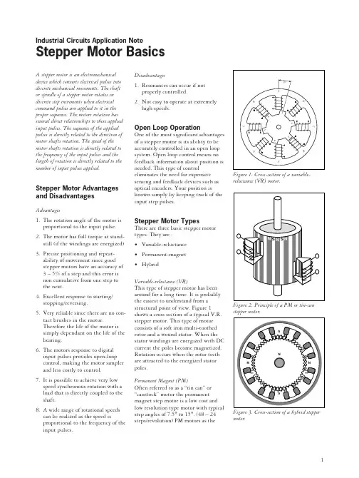
A stepper motor is an electromechanical device which converts electrical pulses into discrete mechanical movements. The shaft or spindle of a stepper motor rotates in discrete step increments when electrical command pulses are applied to it in the proper sequence. The motors rotation has several direct relationships to these applied input pulses. The sequence of the applied pulses is directly related to the direction of motor shafts rotation. The speed of the motor shafts rotation is directly related to the frequency of the input pulses and the length of rotation is directly related to the number of input pulses applied. Stepper Motor Advantages and Disadvantages Advantages1.The rotation angle of the motor isproportional to the input pulse. 2.The motor has full torque at stand-still (if the windings are energized) 3.Precise positioning and repeat-ability of movement since goodstepper motors have an accuracy of3–5% of a step and this error isnon cumulative from one step tothe next.4.Excellent response to starting/stopping/reversing.5.Very reliable since there are no con-tact brushes in the motor.Therefore the life of the motor issimply dependant on the life of the bearing.6.The motors response to digitalinput pulses provides open-loopcontrol, making the motor simplerand less costly to control.7.It is possible to achieve very lowspeed synchronous rotation with aload that is directly coupled to theshaft.8.A wide range of rotational speedscan be realized as the speed isproportional to the frequency of the input pulses.Disadvantages1.Resonances can occur if notproperly controlled.2.Not easy to operate at extremelyhigh speeds.Open Loop OperationOne of the most significant advantagesof a stepper motor is its ability to beaccurately controlled in an open loopsystem. Open loop control means nofeedback information about position isneeded. This type of controleliminates the need for expensivesensing and feedback devices such asoptical encoders. Your position isknown simply by keeping track of theinput step pulses.Stepper Motor TypesThere are three basic stepper motortypes. They are :•Variable-reluctance•Permanent-magnet•HybridVariable-reluctance (VR)This type of stepper motor has beenaround for a long time. It is probablythe easiest to understand from astructural point of view. Figure 1shows a cross section of a typical V.R.stepper motor. This type of motorconsists of a soft iron multi-toothedrotor and a wound stator. When thestator windings are energized with DCcurrent the poles become magnetized.Rotation occurs when the rotor teethare attracted to the energized statorpoles.Permanent Magnet (PM)Often referred to as a “tin can” or“canstock” motor the permanentmagnet step motor is a low cost andlow resolution type motor with typicalstep angles of 7.5° to 15°. (48 – 24steps/revolution) PM motors as theFigure 1. Cross-section of a variable-reluctance (VR) motor.Industrial Circuits Application NoteStepper Motor Basicsmotor.1name implies have permanent magnets added to the motor structure. The rotor no longer has teeth as with the VR motor. Instead the rotor is magnetized with alternating north and south poles situated in a straight line parallel to the rotor shaft. These magnetized rotor poles provide an increased magnetic flux intensity and because of this the PM motor exhibits improved torque characteristics when compared with the VR type.Hybrid (HB)The hybrid stepper motor is more expensive than the PM stepper motor but provides better performance with respect to step resolution, torque and speed. Typical step angles for the HB stepper motor range from 3.6° to 0.9°(100 – 400 steps per revolution). The hybrid stepper motor combines the best features of both the PM and VR type stepper motors. The rotor is multi-toothed like the VR motor and contains an axially magnetized con-centric magnet around its shaft. The teeth on the rotor provide an even better path which helps guide the magnetic flux to preferred locations in the airgap. This further increases the detent, holding and dynamic torque characteristics of the motor when com-pared with both the VR and PM types.The two most commonly used types of stepper motors are the permanent magnet and the hybrid types. If a designer is not sure which type will best fit his applications requirements he should first evaluate the PM type as it is normally several times less expen-sive. If not then the hybrid motor may be the right choice.There also excist some special stepper motor designs. One is the disc magnet motor. Here the rotor is designed sa a disc with rare earth magnets, See fig. 5 . This motor type has some advantages such as very lowinertia and a optimized magnetic flowpath with no coupling between thetwo stator windings. These qualitiesare essential in some applications.Size and PowerIn addition to being classified by theirstep angle stepper motors are alsoclassified according to frame sizeswhich correspond to the diameter ofthe body of the motor. For instance asize 11 stepper motor has a body di-ameter of approximately 1.1 inches.Likewise a size 23 stepper motor has abody diameter of 2.3 inches (58 mm),etc. The body length may however,vary from motor to motor within thesame frame size classification. As ageneral rule the available torque out-put from a motor of a particular framesize will increase with increased bodylength.Power levels for IC-driven steppermotors typically range from below awatt for very small motors up to 10 –20 watts for larger motors. The maxi-mum power dissipation level orthermal limits of the motor are seldomclearly stated in the motor manu-facturers data. To determine this wemust apply the relationship P␣=V ×I.For example, a size 23 step motor maybe rated at 6V and 1A per phase.Therefore, with two phases energizedthe motor has a rated power dissipa-tion of 12 watts. It is normal practiceto rate a stepper motor at the powerdissipation level where the motor caserises 65°C above the ambient in stillair. Therefore, if the motor can bemounted to a heatsink it is oftenpossible to increase the allowablepower dissipation level. This isimportant as the motor is designed tobe and should be used at its maximumpower dissipation ,to be efficient froma size/output power/cost point of view.When to Use a StepperMotorA stepper motor can be a good choicewhenever controlled movement isrequired. They can be used to advan-tage in applications where you need tocontrol rotation angle, speed, positionand synchronism. Because of the in-herent advantages listed previously,stepper motors have found their placein many different applications. Someof these include printers, plotters,highend office equipment, hard diskdrives, medical equipment, faxmachines, automotive and many more.The Rotating Magnetic FieldWhen a phase winding of a steppermotor is energized with current amagnetic flux is developed in thestator. The direction of this flux isdetermined by the “Right HandRule” which states:“If the coil is grasped in the righthand with the fingers pointing in thedirection of the current in the winding(the thumb is extended at a 90° angleto the fingers), then the thumb willpoint in the direction of the magneticfield.”Figure 5 shows the magnetic fluxpath developed when phase B is ener-gized with winding current in thedirection shown. The rotor then alignsitself so that the flux opposition isminimized. In this case the motorwould rotate clockwise so that itssouth pole aligns with the north poleof the stator B at position 2 and itsnorth pole aligns with the south poleof stator B at position 6. To get themotor to rotate we can now see thatwe must provide a sequence ofenergizing the stator windings in sucha fashion that provides a rotatingmagnetic flux field which the rotorfollows due to magnetic attraction.Torque GenerationThe torque produced by a steppermotor depends on several factors.• The step rate• The drive current in the windings• The drive design or typeIn a stepper motor a torque is devel-oped when the magnetic fluxes of therotor and stator are displaced fromeach other. The stator is made up of ahigh permeability magnetic material.The presence of this high permeabilitymaterial causes the magnetic flux tobe confined for the most part to thepaths defined by the stator structurein the same fashion that currents areconfined to the conductors of an elec-tronic circuit. This serves to concen-trate the flux at the stator poles. Thedeveloped by Portescap.23two-pole stepper motor with a lag between the rotor and stator.stepper motors.torque output produced by the motor is proportional to the intensity of the magnetic flux generated when the winding is energized.The basic relationship which defines the intensity of the magnetic flux is defined by:H = (N ×i)÷l where:N =The number of winding turnsi =currentH =Magnetic field intensity l =Magnetic flux path length This relationship shows that the magnetic flux intensity and conse-quently the torque is proportional to the number of winding turns and the current and inversely proportional to the length of the magnetic flux path.From this basic relationship one can see that the same frame size stepper motor could have very different torque output capabilities simply by chang-ing the winding parameters. More detailed information on how the winding parameters affect the output capability of the motor can be found in the application note entitled “Drive Circuit Basics”.Phases, Poles and Stepping AnglesUsually stepper motors have two phases, but three- and five-phase motors also exist.A bipolar motor with two phases has one winding/phase and a unipolar motor has one winding, with a center tap per phase. Sometimes the unipolar stepper motor is referred to as a “four-phase motor”, even though it only has two phases.Motors that have two separate windings per phase also exist—these can be driven in either bipolar or unipolar mode.A pole can be defined as one of the regions in a magnetized body where the magnetic flux density is con-centrated. Both the rotor and the stator of a step motor have poles.Figure 2 contains a simplified picture of a two-phase stepper motor having 2poles (or 1 pole pairs) for each phase on the stator, and 2 poles (one pole pair) on the rotor. In reality several more poles are added to both the rotor and stator structure in order toincrease the number of steps per revolution of the motor, or in other words to provide a smaller basic (full step) stepping angle. The permanent magnet stepper motor contains an equal number of rotor and stator pole pairs. Typically the PM motor has 12pole pairs. The stator has 12 pole pairs per phase. The hybrid type stepper motor has a rotor with teeth. The rotor is split into two parts, separated by a permanant magnet—making half of the teeth south poles and half north poles.The number of pole pairs is equal to the number of teeth on one of the rotor halves. The stator of a hybrid motor also has teeth to build up a higher number of equivalent poles (smaller pole pitch, number of equivalent poles = 360/teeth pitch)compared to the main poles, on which the winding coils are wound. Usually 4 main poles are used for 3.6 hybrids and 8 for 1.8- and 0.9-degree types.It is the relationship between the number of rotor poles and the equival-ent stator poles, and the number the number of phases that determines the full-step angle of a stepper motor.Step angle=360÷(N Ph ×Ph)=360/N N Ph =Number of equivalent poles perphase = number of rotor poles Ph =Number of phases N=Total number of poles for all phases togetherIf the rotor and stator tooth pitch is unequal, a more-complicated relation-ship exists.Stepping ModesThe following are the most common drive modes.• Wave Drive (1 phase on)• Full Step Drive (2 phases on)• Half Step Drive (1 & 2 phases on)• Microstepping (Continuously varying motor currents)For the following discussions please refer to the figure 6.In Wave Drive only one winding is energized at any given time. The stator is energized according to the sequence A → B →A → B and the rotor steps from position 8 → 2 → 4→ 6. For unipolar and bipolar woundmotors with the same winding param-eters this excitation mode would result in the same mechanical position. The disadvantage of this drive mode is that in the unipolar wound motor you are only using 25% and in the bipolar motor only 50% of the total motor winding at any given time. This means that you are not getting the maximum torque output from the motor4Table 1. Excitation sequences for different drive modesFigure 7. Torque vs. rotor angular position.Figure 8. Torque vs. rotor angle position at different holding torque.In Full Step Drive you are ener-gizing two phases at any given time.The stator is energized according to the sequence AB →A B →A B →A B and the rotor steps from position 1 → 3 → 5 → 7 . Full step mode results in the same angular movement as 1 phase on drive but the mechanical position is offset by one half of a full step. The torque output of theunipolar wound motor is lower than the bipolar motor (for motors with the same winding parameters) since the unipolar motor uses only 50% of the available winding while the bipolar motor uses the entire winding.Half Step Drive combines both wave and full step (1&2 phases on)drive modes. Every second step only one phase is energized and during the other steps one phase on each stator.The stator is energized according to the sequence AB → B →A B →A →A B → B → A B → A and the rotor steps from position 1 → 2 → 3→ 4 → 5 → 6 → 7 → 8. This results in angular movements that are half of those in 1- or 2-phases-on drive modes. Half stepping can reduce a phenomena referred to as resonance which can be experienced in 1- or 2-phases-on drive modes.The displacement angle is deter-mined by the following relationship:X = (Z ÷2π)×sin (T a ÷T h )where:Z =rotor tooth pitch T a =Load torqueT h =Motors rated holding torque X =Displacement angle.Therefore if you have a problem with the step angle error of the loaded motor at rest you can improve this by changing the “stiffness” of the motor.This is done by increasing the holding torque of the motor. We can see this effect shown in the figure 5.Increasing the holding torque for a constant load causes a shift in the lag angle from Q 2 to Q 1.Step Angle AccuracyOne reason why the stepper motor has achieved such popularity as a position-ing device is its accuracy and repeat-ability. Typically stepper motors will have a step angle accuracy of 3–5%of one step. This error is also non-cumulative from step to step. The accuracy of the stepper motor is mainly a function of the mechanical precision of its parts and assembly.Figure 9 shows a typical plot of the positional accuracy of a stepper motor.Step Position ErrorThe maximum positive or negative position error caused when the motor has rotated one step from the previous holding position.Step position error = measured step angle - theoretical anglePositional ErrorThe motor is stepped N times from an initial position (N = 360°/step angle)and the angle from the initial positionTorque Angle T LoadT H1T H2O O 12ONormal Wave Drive full step Half-step drive Phase 1234123412345678A ••••••B ••••••A ••••••B••••••The excitation sequences for the above drive modes are summarized in Table 1.In Microstepping Drive the currents in the windings arecontinuously varying to be able to break up one full step into many smaller discrete steps. Moreinformation on microstepping can be found in the microstepping chapter.Torque vs, Angle CharacteristicsThe torque vs angle characteristics of a stepper motor are the relationship between the displacement of the rotor and the torque which applied to the rotor shaft when the stepper motor is energized at its rated voltage. An ideal stepper motor has a sinusoidal torque vs displacement characteristic as shown in figure 8.Positions A and C represent stable equilibrium points when no external force or load is applied to the rotor shaft. When you apply an external force T a to the motor shaft you in essence create an angulardisplacement, Θa . This angular displacement, Θa , is referred to as a lead or lag angle depending on wether the motor is actively accelerating or decelerating. When the rotor stops with an applied load it will come to rest at the position defined by this displacement angle. The motordevelops a torque, T a , in opposition to the applied external force in order to balance the load. As the load isincreased the displacement angle also increases until it reaches themaximum holding torque, T h , of the motor. Once T h is exceeded the motor enters an unstable region. In this region a torque is the opposite direction is created and the rotor jumps over the unstable point to the next stable point.5Figure 9. Positional accuracy of a stepper motor.Figure 10. Torque vs. speed characteristics of a stepper motor.is measured at each step position. If the angle from the initial position to the N-step position is ΘN and the error is ∆ΘN where:∆ΘN = ∆ΘN - (step angle) × N.The positional error is the difference of the maximum and minimum but is usually expressed with a ± sign. That is:positional error = ±1⁄2(∆ΘMax - ∆ΘMin )Hysteresis Positional ErrorThe values obtained from the measure-ment of positional errors in both directions.Mechanical Parameters,Load, Friction, InertiaThe performance of a stepper motor system (driver and motor) is also highly dependent on the mechanical parameters of the load. The load is defined as what the motor drives. It is typically frictional, inertial or a combination of the two.Friction is the resistance to motion due to the unevenness of surfaces which rub together. Friction is constant with velocity. A minimum torque level is required throughout the step in over to overcome thisfriction ( at least equal to the friction).Increasing a frictional load lowers the top speed, lowers the acceleration and increases the positional error. The converse is true if the frictional load is loweredInertia is the resistance to changes in speed. A high inertial load requires a high inertial starting torque and the same would apply for braking. In-creasing an inertial load will increase speed stability, increase the amount of time it takes to reach a desired speed and decrease the maximum self start pulse rate. The converse is again true if the inertia is decreased.The rotor oscillations of a stepper motor will vary with the amount of friction and inertia load. Because of this relationship unwanted rotor oscil-lations can be reduced by mechanical damping means however it is more often simpler to reduce theseunwanted oscillations by electrical damping methods such as switch from full step drive to half step drive.Torque vs, Speed CharacteristicsThe torque vs speed characteristics are the key to selecting the right motor and drive method for a specificapplication. These characteristics are dependent upon (change with) the motor, excitation mode and type of driver or drive method. A typical “speed – torque curve” is shown in figure9.To get a better understanding of this curve it is useful to define the different aspect of this curve.Holding torqueThe maximum torque produced by the motor at standstill.Pull-In CurveThe pull-in curve defines a area refered to as the start stop region. This is the maximum frequency at which the motor can start/stop instantaneously,with a load applied, without loss of synchronism.Maximum Start RateThe maximum starting step frequency with no load applied.Pull-Out CurveThe pull-out curve defines an area refered to as the slew region. It defines the maximum frequency at which the motor can operate without losing syn-chronism. Since this region is outside the pull-in area the motor must ramped (accelerated or decelerated)into this region.Maximum Slew RateThe maximum operating frequency of the motor with no load applied.The pull-in characteristics vary also depending on the load. The larger the load inertia the smaller the pull-in area. We can see from the shape of the curve that the step rate affects the torque output capability of stepper motor The decreasing torque output as the speed increases is caused by the fact that at high speeds the inductance of the motor is the dominant circuit element.TorqueSpeedP.P.S.Start-Stop RegionPull-in Torque curveSlew RegionHolding TorquePull-out Torque Curve Max Start Rate Max Slew RateThe shape of the speed - torque curve can change quite dramatically depending on the type of driver used.The bipolar chopper type drivers which Ericsson Components produces will maximum the speed - torque performance from a given motor. Most motor manufacturers provide these speed - torque curves for their motors.It is important to understand what driver type or drive method the motor manufacturer used in developing their curves as the torque vs. speed charac-teristics of an given motor can vary significantly depending on the drive method used.Stepper motors can often exhibit a phenomena refered to as resonance at certain step rates. This can be seen as a sudden loss or drop in torque at cer-tain speeds which can result in missed steps or loss of synchronism. It occurs when the input step pulse rate coin-cides with the natural oscillation frequency of the rotor. Often there is a resonance area around the 100 – 200 pps region and also one in the highstep pulse rate region. The resonance phenomena of a stepper motor comes from its basic construction and there-fore it is not possible to eliminate it completely. It is also dependent upon the load conditions. It can be reduced by driving the motor in half or micro-stepping modes.Figure 11. Single step response vs. time.Single Step Response and ResonancesThe single-step response character-istics of a stepper motor is shown in figure 11.When one step pulse is applied to a stepper motor the rotor behaves in a manner as defined by the above curve. The step time t is the time it takes the motor shaft to rotate one step angle once the first step pulse is applied. This step time is highly dependent on the ratio of torque to inertia (load) as well as the type of driver used.Since the torque is a function of the displacement it follows that the accel-eration will also be. Therefore, when moving in large step increments a high torque is developed and consequently a high acceleration. This can cause overshots and ringing as shown. The settling time T is the time it takes these oscillations or ringing to cease. In certain applications this phenomena can be undesirable. It is possible to reduce or eliminate this behaviour by microstepping the stepper motor. For more information on microstepping please consult the microstepping note.Anglet TTime O6。
步进电机简介s tepper motors2007-03-08 20:28步进电机在去有机床的生产车间都基本上有见过,但主要都是在数控机床,机床呢好象都用了私服电机步进电机我也有玩过一下是一个简易的数控平台设计我做了下位机和上位机的几乎所有程序下位机用了一天一夜用汇编写的 1千多行好恐怖因为赶着交很多其实还没写好插补还实现不了只是留了接口但终究没找到一个现成的又没时间要赶着做上位机的程序!!!!!也搞了一天也来不及做好就验收了~~~~更巧的是验收时步进电机出了问题没被细问~~险啊!!!!三天把人家三个星期的工作都做了已经很不容易了啊在这三天只吃了一顿米饭其他时间 --北方大饼!!来自/Control-Technology/Motor-Control-Circuits/steppe r-motors.htm一、前言步进电机是将电脉冲信号转变为角位移或线位移的开环控制元件。
在非超载的情况下,电机的转速、停止的位置只取决于脉冲信号的频率和脉冲数,而不受负载变化的影响,即给电机加一个脉冲信号,电机则转过一个步距角。
这一线性关系的存在,加上步进电机只有周期性的误差而无累积误差等特点。
使得在速度、位置等控制领域用步进电机来控制变的非常的简单。
虽然步进电机已被广泛地应用,但步进电机并不能象普通的直流电机,交流电机在常规下使用。
它必须由双环形脉冲信号、功率驱动电路等组成控制系统方可使用。
因此用好步进电机却非易事,它涉及到机械、电机、电子及计算机等许多专业知识。
目前,生产步进电机的厂家的确不少,但具有专业技术人员,能够自行开发,研制的厂家却非常少,大部分的厂家只一、二十人,连最基本的设备都没有。
仅仅处于一种盲目的仿制阶段。
这就给用户在产品选型、使用中造成许多麻烦。
签于上述情况,我们决定以广泛的感应子式步进电机为例。
叙述其基本工作原理。
望能对广大用户在选型、使用、及整机改进时有所帮助。
二、感应子式步进电机工作原理(一)反应式步进电机原理由于反应式步进电机工作原理比较简单。