6200 DHCP Snooping 手册
- 格式:pdf
- 大小:410.06 KB
- 文档页数:11

信锐AC6200Sundray基础配置操作手册信锐AC6200 Sundray基础配置操作手册序言感谢您选择信锐AC6200 Sundray产品作为您的网络设备。
本操作手册将为您提供关于该产品的基础配置说明。
在阅读本手册之前,请确保您已经正确安装了设备并连接到网络。
一、产品概述信锐AC6200 Sundray是一款高性能的企业级路由器,具有强大的数据包处理能力和丰富的网络功能。
它可以提供稳定可靠的网络连接,并支持多种安全策略和管理功能。
二、硬件连接1. 电源连接:将适配器插头插入设备的电源接口,并将适配器的另一端插入电源插座。
2. 网络连接:将设备的WAN端口与网络中的宽带接入设备连接,并使用网线将设备的LAN端口与计算机、交换机等终端设备连接。
三、登录设备1. 打开您的计算机,并确保计算机与设备连接正常。
2. 打开您的浏览器,输入设备的默认IP地址(一般为192.168.1.1)并按下回车键。
3. 在弹出的登录界面中,输入默认的用户名和密码(一般为admin/admin),然后点击“登录”按钮。
4. 如果输入的用户名和密码正确,您将成功登录到设备的管理界面。
四、基本配置1. 网络设置a. 在管理界面上方的菜单栏中选择“网络设置”选项。
b. 在网络设置页面中,根据您的网络环境进行配置。
您可以设置网络接口类型、IP地址、子网掩码、网关等参数。
c. 配置完成后,点击“保存”按钮,设备将会重新进行网络配置。
请留意此时设备可能会断开与您的计算机的连接。
2. 无线设置a. 在管理界面上方的菜单栏中选择“无线设置”选项。
b. 在无线设置页面中,您可以为无线网络设置名称、加密方式、密码等参数。
确保设置的参数符合您的安全需求。
c. 配置完成后,点击“保存”按钮,设备将会重新进行无线网络配置。
请注意此时无线网络可能会断开,您需要重新连接到您的无线网络。
3. 安全设置a. 在管理界面上方的菜单栏中选择“安全设置”选项。

DHCP Snooping功能与实例详解架设DHCP服务器可以为客户端自动分配IP地址、掩码、默认网关、DNS服务器等网络参数,简化了网络配置,提高了管理效率。
但在DHCP服务的管理上存在一些问题,常见的有:●DHCP Server的冒充●DHCP Server的DOS攻击,如DHCP耗竭攻击●某些用户随便指定IP地址,造成IP地址冲突1、DHCP Server的冒充由于DHCP服务器和客户端之间没有认证机制,所以如果在网络上随意添加一台DHCP 服务器,它就可以为客户端分配IP地址以及其他网络参数。
只要让该DHCP服务器分配错误的IP地址和其他网络参数,那就会对网络造成非常大的危害。
2、DHCP Server的拒绝服务攻击通常DHCP服务器通过检查客户端发送的DHCP请求报文中的CHADDR(也就是Client MAC address)字段来判断客户端的MAC地址。
正常情况下该CHADDR字段和发送请求报文的客户端真实的MAC地址是相同的。
攻击者可以利用伪造MAC的方式发送DHCP请求,但这种攻击可以使用Cisco 交换机的端口安全特性来防止。
端口安全特性(Port Security)可以限制每个端口只使用唯一的MAC地址。
但是如果攻击者不修改DHCP请求报文的源MAC地址,而是修改DHCP报文中的CHADDR字段来实施攻击,那端口安全就不起作用了。
由于DHCP服务器认为不同的CHADDR值表示请求来自不同的客户端,所以攻击者可以通过大量发送伪造CHADDR的DHCP请求,导致DHCP服务器上的地址池被耗尽,从而无法为其他正常用户提供网络地址,这是一种DHCP耗竭攻击。
DHCP耗竭攻击可以是纯粹的DOS攻击,也可以与伪造的DHCP服务器配合使用。
当正常的DHCP服务器瘫痪时,攻击者就可以建立伪造的DHCP服务器来为局域网中的客户端提供地址,使它们将信息转发给准备截取的恶意计算机。
甚至即使DHCP请求报文的源MAC地址和CHADDR字段都是正确的,但由于DHCP请求报文是广播报文,如果大量发送的话也会耗尽网络带宽,形成另一种拒绝服务攻击。

阿尔卡特朗讯OmniStack LS 6200 21世纪的工作组交换机OS-LS-6212/6212P OS-LS-62248UVLAN支持●255个VLAN●支持4094个VLAN标记●基于端口、802.1Q、MAC、IP子网和协议的VLAN●VLAN堆栈(Q in Q)●组播TV VLAN支持高可用性●802.1w 快速恢复生成树协议允许针对冗余链路的二次恢复●802.1d 生成树协议用于回环拓扑和冗余链路●802.1s 多链路生成树●用户端口上的快速转发模式对生成树支持30秒钟的延迟●静态的和802.3ad 动态链路捆绑支持与其他交换机链路捆绑的自动配置●广播风暴控制●冗余的1:1电源备份●堆叠环容错●可选的基于OS6200的DC电源(非PoE模式)服务质量保证●802.1p,TOS,DSCP标记●QoS映射:802.1p到TOS/DSCP,TOS到802.1p/DSCP,DSCP到802.1p/TOS●每端口分类802.1p(CoS)值、MAC源/目的地址、以太网类型、ToS 优先级、DSCP值、ICMP代码和类型、IP源/目的地址、IP协议、TCP/UDP端口●每端口4个出口队列,支持精确的或WRR队列算法可针对特定需要方便的进行设置●基于端口/流的入口带宽限速●基于端口/队列的出口带宽限速高级安全性●基于业界标准的802.1x身份认证及多用户模式●802.1x多客户端,多VLAN支持用于每个客户端的认证和VLAN分配●为非授权用户提供访客VLAN提供有限的网络接入●可学习的端口安全性或MAC地址锁定只允许已知的设备实现网络接入,防护未经授权的网络设备接入。
●RADIUS 和TACACS+ 管理员认证用于防范未经授权的交换机管理●DHCP OPTION 82和DHCP SNOOPING保护IP安全●Secure Shell(SSH),安全套接层(SSL)和SNMPv3用于远程管理通讯的加密●访问控制列表可过滤不需要的流量包括拒绝访问式攻击●访问控制列表可基于每个端口、MAC源/目的地址、IP源/目的地址、ICMP代码和类型、以太网类型、TCP/UDP端口> 4 alcatel-lucent●生成树根防护技术可防止未经授权的设备变成生成树的根性能●交换容量:12.8Gbps OS-LS-6212/12P/24/24P/24U,17.6Gbps OS-LS-6248/48P●堆叠容量:每个堆叠端口1Gbps,4Gbps的总计流量用于优化单播和组播流量转发●线速的数据包转发,9.52Mpps OS-LS-6224/24P,13.1Mpps OS-LS-6248/48P●8K MAC地址●SFP(mini-GBIC)端口可支持100Base FX光纤转发器以支持100M光纤连接物理尺寸●OS-LS-6212/12P/24/24U:44×23×4.4厘米(宽×深×高)●OS-LS-6224P/48/48P:44×33×4.4厘米(宽×深×高)重量●OS-LS-6212:2.65Kg/OS-LS-6212P:3.0Kg●OS-LS-6224:3.0Kg/OS-LS-6224P:4.45Kg●OS-LS-6248:4.1Kg/OS-LS-6248P:5.5Kg接头/线缆●管理:一个RJ-45控制线接头被配置为DTE模式用于操作、诊断、配置交换机。

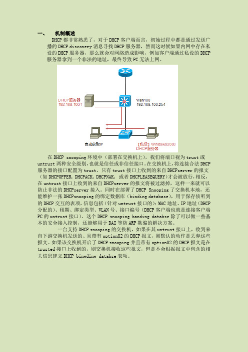
一、机制概述DHCP都非常熟悉了,对于DHCP客户端而言,初始过程中都是通过发送广播的DHCP discovery消息寻找DHCP服务器,然而这时候如果内网中存在私设的DHCP服务器,那么就会对网络造成影响,例如客户端通过私设的DHCP 服务器拿到一个非法的地址,最终导致PC无法上网。
在DHCP snooping环境中(部署在交换机上),我们将端口视为trust或untrust两种安全级别,也就是信任或非信任接口。
在交换机上,将连接合法DHCP 服务器的接口配置为trust。
只有trust接口上收到的来自DHCPserver的报文(如DHCPOFFER, DHCPACK, DHCPNAK, 或者DHCPLEASEQUERY)才会被放行,相反,在untrust接口上收到的来自DHCPserver的报文将被过滤掉,这样一来就可以防止非法的DHCPserver接入。
同时在部署了DHCP Snooping了交换机本地,还能维护一张DHCPsnooping的绑定数据库(binding database),用于保存侦听到的DHCP交互的表项,信息包括(针对untrust接口的):MAC地址、IP地址(DHCP 分配的)、租期、绑定类型、VLAN号、接口编号(DHCP客户端也就是连接客户端PC的untrust接口)。
这个DHCP snooping banding databse除了可以做一些基本的安全接入控制,还能够用于DAI等防ARP欺骗的解决方案。
一台支持DHCP snooping的交换机,如果在其untrust接口上,收到来自下游交换机发送的、且带有option82的DHCP报文,则默认的动作是丢弃这些报文。
如果该交换机开启了DHCP snooping并且带有option82的DHCP报文是在trusted接口上收到的,则交换机接收这些报文,但是不会根据报文中包含的相关信息建立DHCP bingdingdatabse表项。

华为交换机DHCP snooping配置教程DHCP Snooping是一种DHCP安全特性,在配置DHCP Snooping各安全功能之前需首先使能DHCP Snooping功能。
使能DHCP Snooping功能的顺序是先使能全局下的DHCP Snooping功能,再使能接口或VLAN下的DHCP Snooping功能。
图1 配置DHCP Snooping基本功能组网图如上图1所示,Switch_1是二层接入设备,将用户PC的DHCP请求转发给DHCP服务器。
以Switch_1为例,在使能DHCP Snooping功能时需要注意:使能DHCP Snooping功能之前,必须已使用命令dhcp enable使能了设备的DHCP功能。
全局使能DHCP Snooping功能后,还需要在连接用户的接口(如图中的接口if1、if2和if3)或其所属VLAN(如图中的VLAN 10)使能DHCP Snooping 功能。
当存在多个用户PC属于同一个VLAN时,为了简化配置,可以在这个VLAN 使能DHCP Snooping功能。
请在二层网络中的接入设备或第一个DHCP Relay上执行以下步骤。
1、使能DHCP Snooping功能[Huawei]dhcp snooping enable ?ipv4 DHCPv4 Snoopingipv6 DHCPv6 Snoopingvlan Virtual LAN<cr>或[Huawei]dhcp snooping over-vpls enable # 使能设备在VPLS网络中的DHCP Snooping功能或[Huawei-vlan2]dhcp snooping enable[Huawei-GigabitEthernet0/0/3]dhcp snooping enable2、配置接口信任状态[Huawei-GigabitEthernet0/0/2]dhcp snooping trusted或[Huawei-vlan3]dhcp snooping trusted interface GigabitEthernet 0/0/63、去使能DHCP Snooping用户位置迁移功能在移动应用场景中,若某一用户由接口A上线后,切换到接口B重新上线,用户将发送DHCP Discover报文申请IP地址。
Dell™ PowerConnect™6200 Series Stackable SwitchesGetting Started Guide使用入门指南Příručka ZačínámeGuide de mise en routeErste SchritteΟδηγός για γρήγορο ξεκίνηµαはじめに시작 설명서Instrukcja uruchomieniaGuía de introducciónBaşlangıç KılavuzuModels PC6224, PC6248, PC6224P, PC6248P, and PC6224Fw w w.d e l l.c o m|s u p p o r t.d e l l.c o mDell™ PowerConnect™6200 Series Stackable SwitchesGetting Started GuideModels PC6224, PC6248, PC6224P, PC6248P, and PC6224Fw w w.d e l l.c o m|s u p p o r t.d e l l.c o mNotes, Notices, and CautionsNOTE: A NOTE indicates important information that helps you make better use of your computer.NOTICE: A NOTICE indicates either potential damage to hardware or loss of data and tells you how to avoid the problem.CAUTION: A CAUTION indicates a potential for property damage, personal injury, or death.____________________Information in this document is subject to change without notice.©2007Dell Inc.All rights reserved.Reproduction in any manner whatsoever without the written permission of Dell Inc.is strictly forbidden.Trademarks used in this text: Dell, the DELL logo, and PowerConnect are trademarks of Dell Inc.; Microsoft and Windows are registered trademarks of Microsoft Corporation.Other trademarks and trade names may be used in this document to refer to either the entities claiming the marks and names or their products. Dell Inc. disclaims any proprietary interest in trademarks and trade names other than its own.Models PC6224, PC6248, PC6224P, PC6248P, and PC6224FSeptember 2007P/N YC897Rev. A02Contents1InstallationSite Preparation (5)Unpacking the Switch (5)Package Contents (5)Unpacking Steps (6)Mounting the Switch (6)Installing in a Rack (6)Installing as a Free-standing Switch (7)Connecting a Switch to a Terminal (7)Connecting a Switch to a Power Supply (7)Assembling a Stack (8)2Starting and Configuring the SwitchConnecting the Terminal to the Switch (10)Booting the Switch (11)Initial Configuration (12)Initial Configuration Procedure (12)Example Session (13)Contents33Managing a StackMaster and Member Switches (16)Stack Startup (16)Topology Discovery (16)Auto Stack ID Assignment (16)Firmware Version Checking (16)System Initialization (17)CLI/ Telnet/ Web Interface (17)Insertion and Removal of Switches (17)Operating as Standalone Switch (17)Stack ID Renumbering (17)User Controls (18)4Front Panels and LEDsFront Panels (19)LEDs (20)Systems LEDs (20)RJ-45 LEDs (PoE) (21)XFP LED (21)SFP LED (21)4ContentsInstallationThis document provides basic information to install, configure, and operate Dell™PowerConnect™ PC6224, PC6248, PC6224P, PC6248P, and PC6224F systems. For more information, see the User's Guide, which is available on your User Documentation CD, or check the Dell Support web site at for the latest updates on documentation and firmware.Site PreparationPowerConnect 6200 series switches can be mounted in a standard 48.26-cm (19-inch) rack or left freestanding (placed on a flat surface). These switches can function as stand-alone switches. They can also be installed as a stack of switches that function, and are managed, as a single entity.Before installing the switch or switches, make sure that the chosen installation location meets the following site requirements:•Power — The switch is installed near an easily accessible 100–250 VAC, 50–60 Hz outlet. •Clearance — There is adequate front and rear clearance for operator access. Allow clearance for cabling, power connections, and ventilation.•Cabling — The cabling is routed to avoid sources of electrical noise such as radio transmitters, broadcast amplifiers, power lines, and fluorescent lighting fixtures.•Ambient — The ambient switch operating temperature range is 0 to 45ºC (32 to 113ºF) at a relative humidity of up to 95 percent, non-condensing.Unpacking the SwitchPackage ContentsWhen unpacking each switch, make sure that the following items are included:•One PowerConnect switch•One AC power cable•One RS-232 cable•One rack-mount kit for rack installation (two mounting brackets, bolts, and cage nuts)•One set of self-adhesive rubber pads for the free-standing switch (four pads are included)•User Documentation CD•Getting Started Guide•Product Information GuideGetting Started Guide56Getting Started Guidew w w .d e l l .c o m | s u p p o r t .d e l l .c o m Unpacking StepsNOTE: Before unpacking the switch, inspect the container and immediately report any evidence of damage.1Place the container on a clean, flat surface and cut all straps securing the container.2Open the container or remove the container top.3Carefully remove the switch from the container and place it on a secure and clean surface.4Remove all packing material.5Inspect the product and accessories for damage.Mounting the Switch CAUTION: Read the safety information in the Product Information Guide as well as the safety information for otherswitches that connect to or support the switch.The AC and DC power connectors are on the back panel of the switch. We recommend connecting a redundant power supply, such as the PowerConnect RPS-600 for non-PoE switches or the PowerConnect EPS-470 for PoE switches.Installing in a RackCAUTION: Do not use rack mounting kits to suspend the switch from under a table or desk, or attach it to a wall. CAUTION: Disconnect all cables from the switch before continuing. Remove all self-adhesive pads from theunderside of the switch, if they have been attached.CAUTION: When mounting multiple switches into a rack, mount the switches from the bottom up.1Place the supplied rack-mounting bracket on one side of the switch, ensuring that the mounting holes onthe switch line up to the mounting holes in the rack-mounting bracket. Figure 1-1 illustrates where tomount the brackets.Figure 1-1.Attaching the Brackets 2Insert the supplied bolts into the rack-mounting holes and tighten with a screwdriver. 3Repeat the process for the rack-mounting bracket on the other side of the switch.Getting Started Guide 74Insert the switch into the 48.26 cm (19 inch) rack, ensuring that the rack-mounting holes on the switch line up to the mounting holes in the rack.5Secure the switch to the rack with either the rack bolts or cage nuts and cage nut bolts with washers(depending on the kind of rack you have). Fasten the bolts on bottom before fastening the bolts on top.NOTICE: Make sure that the ventilation holes are not obstructed.CAUTION: Make sure that the supplied rack bolts fit the pre-threaded holes in the rack.Installing as a Free-standing Switch NOTICE:We strongly recommend mounting the switch in a rack.Install the switch on a flat surface if you are not installing it in a rack. The surface must be able to support the weight of the switch and the switch cables. The switch is supplied with four self-adhesive rubber pads.1Attach the self-adhesive rubber pads on each location marked on the bottom of the switch.2Set the switch on a flat surface, and make sure that it has proper ventilation by leaving 5 cm (2 inches)on each side and 13 cm (5inches) at the back.Connecting a Switch to a Terminal1Connect the supplied RS-232 cable to a VT100 terminal or to the serial connector of a personal computer running VT100 terminal emulation software.2Connect the female DB-9 connector at the other end of the RS-232 crossover cable to the serial portconnector on the rear of the switch.NOTE: If you are installing a stack of switches , connect the terminal to the Master Switch. This switch will light the Master Switch LED, the top left LED in the array on the front panel. When a stack is powered up for the first time, the switches elect the Master Switch, which may occupy any location in the stack. If you connect the terminal to a member switch, you will not be able to use the CLI.Connecting a Switch to a Power SupplyCAUTION: Read the safety information in the Product Information Guide as well as the safety information for other switches that connect to or support the switch.1Connect the supplied AC power cable to the AC power connector located on the back panel. Figure 1-2 illustrates where to connect the power cable.2To provide a redundant source of power, connect the 12 VDC power cable from a (separately purchased)PowerConnect RPS-600 for non-PoE switches or PowerConnect EPS-470 for PoE switches to the DC power connector located on the back panel.NOTE: Do not connect the power cable to a grounded AC outlet at this time. Connect the switch to a power source as described in the step detailed in "Starting and Configuring the Switch."8Getting Started Guide w w w .d e l l .c o m | s u p p o r t.d el l .c o m Figure 1-2.Connecting Power CableAssembling a StackY ou can stack PowerConnect 6200 series switches up to 12 switches high, supporting up to 576 front panel ports. Create a stack by connecting adjacent units using the stacking ports on the left side of the switch rear. See Figure 1-3.NOTE: The switches must be turned off as they are added to a stack.1Install a separately purchased stacking module in rear "Bay 1" in each of the switches to be stacked.2Use the cables supplied with the stacking modules to connect from one switch to the next until all switches are connected in a ring.3Make sure that the last stacking cable is connected from the last switch to the first switch to create a loop. 4If necessary, use a separately purchased three-meter stacking cable to connect the switches.Figure 1-3.Connecting a Stack of SwitchesNOTE: Long cable not shown in Figure1-3.The resulting ring topology allows the entire stack to function as a single switch with resilient fail-over capabilities.w w w .d e l l .c o m | s u p p o r t .d e l l .c o m Starting and Configuring the Switch After completing all external connections, connect a terminal to a switch to configure the switch or stack. Additional advanced functions are described in the User's Guide located on your User Documentation CD. NOTE: Read the release notes for this product before proceeding. You can download the release notes from the Dell Support website at . NOTE: We recommend that you obtain the most recent version of the user documentation from the Dell Support website at .Connecting the Terminal to the Switch To monitor and configure the switch via serial console, use the console port on the rear of the switch to connectit to a terminal desktop system running terminal emulation software. The console port connector is a male DB-9 connector, implemented as a data terminal equipment (DTE) connector.The following is required to use the console port:•VT100-compatible terminal or a desktop or a portable system with a serial port, running VT100 terminal emulation software.•An RS-232 crossover cable with a female DB-9 connector for the console port and the appropriateconnector for the terminal.Perform the following tasks to connect a terminal to the switch console port:NOTE: If you are installing a stack of switches , you need to assemble and cable the stack before powering upand configuring the stack.1Connect an RS-232 crossover cable to the terminal running VT100 terminal emulation software.2Configure the terminal emulation software as follows:aSelect the appropriate serial port (serial port 1 or serial port 2) to connect to the console.bSet the data rate to 9600 baud.cSet the data format to 8 data bits, 1 stop bit, and no parity.dSet the flow control to none.eSet the terminal emulation mode to VT100.f Select Terminal keys for Function, Arrow, and Ctrl keys. Make sure that the setting is for Terminal keys(not Microsoft ® Windows ® keys).NOTE: When using HyperTerminal with Microsoft Windows 2000, make sure that you have Windows 2000 Service Pack 2 or later installed. With Windows 2000 Service Pack 2, the arrow keys function properly in HyperTerminal's VT100emulation. Go to for more information on Windows 2000 service packs.3Connect the female connector of the RS-232 crossover cable directly to the switch console port, and tighten the captive retaining bolts. The PowerConnect 6200 series console ports are located on the rear panel as shown in Figure1-4.NOTE: If you are installing a stack of switches, connect the terminal to the Master Switch. This switch will light the Master Switch LED, the top left LED in the array on the front panel. When a stack is powered up for the first time, the switches elect the Master Switch, which may occupy any location in the stack. If you connect the terminal to a member switch, you will not be able to use the CLI.Figure 1-4.Connecting to the Console PortBooting the Switch1Make sure that the switch console port is connected to a VT100 terminal or VT100 terminal emulator via the RS-232 cable.2Locate an AC power receptacle.3Deactivate the AC power receptacle.4Connect the switch to the AC receptacle.5Activate the AC power receptacle.When the power is turned on with the local terminal already connected, the switch goes through a power-on self-test (POST). POST runs every time the switch is initialized and checks hardware components to determine if the switch is fully operational before completely booting. If POST detects a critical problem, the program flow stops. If POST passes successfully, valid firmware is loaded into RAM. POST messages are displayed on the terminal and indicate test success or failure. The boot process runs for approximately 60 seconds.w w w .d e l l .c o m | s u p p o r t .d e l l .c o m Initial Configuration NOTE: The initial simple configuration procedure is based on the following assumptions:•The PowerConnect switch was never configured before and is in the same state as when you received it.•The PowerConnect switch booted successfully.•The console connection was established and the Dell Easy Setup Wizard prompt appears on the screen of a VT100 terminal or terminal equivalent.The initial switch configuration is performed through the console port. After the initial configuration, you can manage the switch either from the already-connected console port or remotely through an interface defined during the initial configuration. NOTE: The switch is not configured with a default user name and password.NOTE: All of the settings below are necessary to allow the remote management of the switch through Telnet(Telnet client) or HTTP (Web browser).Before setting up the initial configuration of the switch, obtain the following information from your network administrator:•The IP address to be assigned to the management VLAN through which the switch is managed.•The IP subnet mask for the network.•The IP address of the management VLAN default gateway for configuring the default route.Initial Configuration ProcedureY ou can perform the initial configuration using the Dell Easy Setup Wizard, or by using the Command Line Interface (CLI). The Setup Wizard automatically starts when the switch configuration file is empty. Y ou can exit the wizard at any point by entering [ctrl+z], but all configuration settings specified will be discarded (the switch will use the default values). For more information on CLI initial configuration see the User Guide . This guide shows how to use the Setup Wizard for initial switch configuration. The wizard sets up the followingconfiguration on the switch:•Establishes the initial privileged user account with a valid password. The wizard configures one privileged user account during the setup. •Enables CLI login and HTTP access to use the local authentication setting only.•Sets up the IP address for the management VLAN.•Sets up the SNMP community string to be used by the SNMP manager at a given IP address. Y ou may choose to skip this step if SNMP management is not used for this switch. •Allows you to specify the management server IP or permit management access from all IP addresses.•Configures the default gateway IP address.Example SessionThis section describes an Easy Setup Wizard session. The following values are used by the example session:•IP address for the management VLAN is 192.168.1.100:255.255.255.0.•The user name is admin, and password is admin123.•The network management system IP address is 192.168.1.10.•The default gateway is 192.168.1.1.•The SNMP community string to be used is Dell_Network_Manager.The setup wizard configures the initial values as defined above. After you complete the wizard, the switchis configured as follows:•SNMPv1/2c is enabled and the community string is set up as defined above. SNMPv3 is disabled by default.•The admin user account is set up as defined.• A network management system is configured. From this management station, you can access the SNMP, HTTP, and CLI interfaces. Y ou may also choose to allow all IP addresses to access thesemanagement interfaces by choosing the (0.0.0.0) IP address.•An IP address is configured for the default management VLAN (1).• A default gateway address is configured.NOTE: In the example below, the possible user options are enclosed in [ ]. Also, where possible, the default value is provided in { }. If you press <Enter> with no options defined, the default value is accepted. Help text is in parentheses. The following example contains the sequence of prompts and responses associated with running an example Dell Easy Setup Wizard session, using the input values listed above.After the switch completes the POST and is booted, the following dialog appears:Welcome to Dell Easy Setup WizardThe setup wizard guides you through the initial switch configuration, and gets you up and running as quickly as possible. You can skip the setup wizard, and enter CLI mode to manually configure the switch. You must respond to the next question to run the setup wizard within 60 seconds, otherwise the system will continue with normal operation using the default system configuration. Note: You can exit the setup wizard at any point by entering [ctrl+z].Would you like to run the setup wizard (you must answer this question within 60 seconds)? [Y/N] y<Enter>w w w .d e l l .c o m | s u p p o r t .d e l l .c o m Step 1: The system is not configured for SNMP management by default. To manage the switch using SNMP (required for Dell Open Manage Network Manager) you can:o Set up the initial SNMP version 1 & 2 now.o Return later and set up other SNMP accounts. (For more information on setting up an SNMP version 3 account, see the user documentation). Would you like to configure the SNMP management interface now? [Y/N] y <Enter>To configure the SNMP management account you must specify the management system IP address and the "community string" or password that the particular management system uses to access the switch. The wizard automaticallyassigns the highest access level [Privilege Level 15] to this account. You can use Dell Open Manage Network Manager or other management interfaces to change this setting and to add additional management systems later. For more information on adding management systems, see the User’s Guide.To add a management station:Please enter the SNMP community string to be used {Dell_Network_Manager}: Dell_Network_Manager <Enter>NOTE: If it is configured, the default access level is set to the highest available access for the SNMP management interface. Initially only SNMPv1/2c will be activated. SNMPv3 is disabled until you return to configure security access for SNMPv3 (e.g. engine ID, view, etc.). Please enter the IP address of the Management System (A.B.C.D) or wildcard (0.0.0.0) to manage from any Management Station {0.0.0.0}: 192.168.1.10<Enter>Step 2:Now we need to configure your initial privilege (Level 15) user account. This account is used to login to the CLI and Web interface. You may set up other accounts and change privilege levels later. For more information on setting up user accounts and changing privilege levels, see the User’s Guide.To set up a user account:Please enter the user name {admin}: admin <Enter>Please enter the user password: ********<Enter>Please reenter the user password: ********<Enter>NOTE: If the first and second password entries are not identical, the user is prompted until they are.NOTE: You can create additional user accounts after completing the Easy Setup Wizard. See the User’s Guidefor more information.Step 3:Next, an IP address is set up. The IP address is defined on the default VLAN (VLAN #1), of which all ports are members. This is the IP address you use to access the CLI, Web interface, or SNMP interface for the switch.To set up an IP address:Please enter the IP address of the device (A.B.C.D):192.168.1.100<Enter>Please enter the IP subnet mask (A.B.C.D or /nn):255.255.255.0<Enter>Step 4:Finally, set up the gateway. Please enter the IP address of the gateway from which this network is reachable (e.g. 192.168.1.1): 192.168.1.1<Enter>This is the configuration information that has been collected:SNMP Interface = "Dell_Network_Manager"@192.168.1.10User Account set up = adminPassword = **********Management IP address = 192.168.1.100:255.255.255.0Gateway = 192.168.1.1Step 5:If the information is correct, please select (Y) to save the configuration, and copy to the start-up configuration file. If the information is incorrect, select (N) to discard configuration and restart the wizard: [Y/N] y<Enter>Thank you for using the Dell Easy Setup Wizard. You will now enter CLI mode.w w w .d e l l .c o m | s u p p o r t .d e l l .c o m Managing a Stack Master and Member Switches A stack of switches can be managed as a single entity when connected together. The stack can be managed from a web-based interface, an SNMP management station, or a CLI. When a stack is created, one switch automatically becomes the master switch. Y ou can manually allocate an IP address to the master switch using the console, or let DHCP do so automatically. Afterwards, you can manage the entire stack through the IP address of the Master Switch. The Master Switch detects and reconfigures the ports with minimal operational impact in the event of:•Switch failure •Inter-switch stacking link failure •Switch insertion •Switch removalIf the Master Switch goes off line, any of the Member Switches in the stack can replace it. The system will elect a new Master Switch and reconfigure the System Configuration for the stack.Stack StartupTopology DiscoveryWhen a stack is formed, a topology discovery process builds up a database that contains information about all of the switches in the stack, including the Firmware Version, Hardware Version, Management Preference, Switch MAC Address, and Switch Serial Number. Y ou can use the command line interface or the Web interface to view this information.See the CLI Reference Manual and the User’s Guide for assistance with the CLI and Web interface, respectively.Auto Stack ID AssignmentDuring the stack formation process, every switch is assigned a Stack ID. Once Stack ID assignment is complete, each switch saves its Stack ID into the nonvolatile FLASH memory. Y ou can use the CLI or the Web interface to view the stack IDs.Firmware Version CheckingFollowing Stack ID assignment, the Master Switch performs a consistency check to make sure that all switches in the stack are running the same firmware version.If the switch software versions do not match, then the ports on the member switch will not become valid for operation. This condition is known as the Suspended Stacking Mode. Y ou can then synchronize the firmware on the member switch with the firmware that is running on the Master Switch.System InitializationIf the Master Switch determines during the firmware version consistency check that all switches are running the same version of firmware, the switch will be initialized for Stacking Mode.System Initialization for Normal Stacking ModeThe Master Switch will initialize the stack using the last saved system configuration file. For those switches that do not have a configuration file, the system will apply default settings to those switches.If the configuration file is corrupted, the Master Switch will initialize the stack and set it to the Factory Default Configuration.Y ou can save the configuration file. The Master Switch will automatically distribute the configuration file to the member switches. If the Master Switch later becomes unavailable, a Member Switch can become the new Master Switch and apply the configuration file that was saved on the original Master Switch.System Initialization for Suspended Stacking ModeAfter system initialization is complete, the Master Switch will enter Suspended Stacking Mode if the firmware versions of the stack are inconsistent. In this mode, only the Master Switch is initialized with configuration file information. None of the member switches are initialized. This forces all member switches to remain in non-operational mode.CLI/ Telnet/ Web InterfaceY ou can use the CLI / WEB / SNMP to synchronize the firmware that is stored in the Master Switch to a member switch.Insertion and Removal of SwitchesY ou can insert and remove switches to/from the current stack without cycling the power. The entire network may be affected when a topology change occurs, as a stack reconfiguration will take place. A new Master Switch will not be re-elected, unless the Master Switch was removed from the stack. Stack reconfiguration takes a maximum of two minutes in a stack of twelve switches, less time for smaller stacks.Operating as Standalone SwitchIf a switch cannot detect a stacking partner on a port enabled for stacking, the switch will operate as a standalone switch. If a stacking partner is detected, the switch will always operate in stacking mode.Stack ID RenumberingY ou can manually assign Stack IDs to a switch. A switch can only be assigned a Stack ID that has not already been assigned to another switch in the stack. Any configuration information that was saved for the new Stack ID is applied to the switch that is taking that Stack ID.w w w .d e l l .c o m | s u p p o r t .d e l l .c o m User Controls Use the following CLI commands to control this feature. See the CLI Reference Guide for details on the syntax of each command.movemanagement reload member set description switch priority switch renumberstackingshow stack-portshow stack-port counters show stack-port diag show switchshow supported switchtypeFront Panels and LEDsThis appendix describes the front panels and LEDs of the Dell PowerConnect PC6224, PC6248, PC6224P, PC6248P, and PC6224F systems.Front PanelsThe front panels of the PowerConnect 6200 series systems are shown in the figures below.Figure 1-1.PC 6224PC 6248Figure 1-2.Figure 1-3.Getting Started Guide1920Getting Started Guidew w w .d e l l .c o m | s u p p o r t .d e l l .c o mFigure 1-4.PC 6248PFigure 1-5.PC 6224FLEDsThe following sections list the LEDs.Systems LEDsTable 1-1.System LEDsLED StateFan Status•Green: All Fans are operating correctly •Red: One or more fans have failed Power Supply Status •Green: PS operating correctly •Red: PS failureRedundant Power Supply•Green: Redundant supply present and operating correctly•Red: Redundant supply present and failed •Off: Redundant supply is not presentDiagnostic•Blinking Green: Diagnostics in progress•Solid Green: Diagnostics completed successfully •Red: Diagnostics failedTemperature•Green: System temperature is below threshold limit •Red: System temperature is above threshold limit。
Sundray操作手册——路由模式部署信锐技术有限公司2014年10月目录1部署说明 (3)1.1拓扑图 (3)1.2配置说明 (3)2操作步骤 (4)2.1登录控制器 (4)2.2基础接口配置 (6)2.3基础网络配置 (7)2.4接入点的配置 (9)2.5无线网络配置 (11)1 部署说明本文档旨在促进网络工程师对Sundray产品的了解,文档包含了最基础的网络部署实现,文档采用的部署模式为路由模式。
1.1拓扑图拓扑如图1-1所示,控制器作为无线设备的网关,上联公司网络。
无线AP通过POE交换机进行供电。
注意:无线控制器不能进行PPPOE拨号,如果是ADSL或者PPPOE拨号网络,请在控制器上端部署一个路由设备(或者其他拨号设备)。
图1-1 拓扑图1.2配置说明1.2.1 接线准备如图1-2所示,将控制器的ETH1口上连公司网络,ETH2口下联交换机接口。
配置接口为Manage口。
图1-2 接线图1.2.2 配置说明该部署模式下,控制器作为无线网络的网关,AP的IP地址、无线终端的IP地址都是控制器下发。
如果上层设备不能配置回程路由,需要在控制器上配置网络地址转换NAT。
本示例文档,AP的地址与无线终端的地址隔离,分属两个不同的VLAN,其中AP所在的VLAN为1,无线终端的VLAN为2。
考虑到AP数量较少,无线终端数量较多,配置VLAN1的地址池为192.168.100.0/24网段;由于无线终端比较多,配置VLAN2的地址池为172.16.0.0/16地址段。
假设:控制器IP为:192.168.1.125/24。
网关IP为192.168.1.12 操作步骤对于控制器的操作,地址分为4步,首先进入控制器,然后进行基础接口的配置,配置相应的网络参数,让控制能够上网。
最后是激活AP,并配置相应的无线网络。
2.1登录控制器Sundray产品不开放后台操作,不提供类似思科华三厂商的命令行配置。
进入控制器后台需要遵循如下操作。
交换机配置指导文档文档作者:刘永渝文档密级:内部公开修订日期:2011年12月28 日变更记录注:对该文档内容的增加、删除或修改均需填写此记录,详细记载变更信息,以保证其可追溯性。
目录1前言 (2)1.1文档目的 (2)1.2术语和缩略语 (2)1.3参考资料 (2)2功能概述 (2)3工作原理 (2)4实现方式 (3)5报文流程 ........................................................................................................... 错误!未定义书签。
6应用场景 (4)6.1拓扑结构 (4)6.2场景分析 (4)6.3CLI配置 (4)附录.............................................................................................................................. 错误!未定义书签。
1 前言1.1 文档目的1.2 术语和缩略语【简单描述文档中涉及到的术语和缩略语】1.3 参考资料【罗列出有助于理解该产品功能的相关文档,如RFC或相关书籍等】2 功能概述1.dhcp-snooping的主要作用就是隔绝非法的dhcp server,通过配置非信任端口。
2.与交换机DAI的配合,防止ARP病毒的传播。
3.建立和维护一张dhcp-snooping的绑定表,这张表一是通过dhcp ack包中的ip和mac地址生成的,二是可以手工指定。
这张表是后续DAI(dynamic arp inspect)和IP Source Guard 基础。
这两种类似的技术,是通过这张表来判定ip或者mac地址是否合法,来限制用户连接到网络的。
3 工作原理DHCP Snooping技术是DHCP安全特性,通过建立和维护DHCP Snooping绑定表过滤不可信任的DHCP信息,这些信息是指来自不信任区域的DHCP信息。
OmniStack6200的dhcp-snooping功能简单实现牛文超Niuwc8@【关键字】:DHCP,DHCP Snooping,Dynamic ARP Inspection,IP Source Guard【摘要】:本文就在网络中使用DHCP服务时经常会遇到由于的用户指定IP地址,而造成的IP地址分配问题,并且网络中常见的ARP攻击(伪造IP地址/MAC地址攻击)提出了解决办法,并给出了在ALCATEL交换机上的具体实例。
一、引言DHCP(动态主机配置协议)是一种简化主机IP地址配置管理的TCP/IP标准。
该标准为DHCP服务器的使用提供了一种有效的方法:即管理网络中客户机IP地址的动态分配以及启用网络上DHCP客户机的其它相关配置信息。
在基于TCP/IP协议的网络中,每台计算机都必须有唯一的IP地址才能访问网络上的资源,网络中计算机之间的通信是通过IP地址来实现的,并且通过IP地址和子网掩码来标识主计算机及其所连接的子网。
在局域网中如果计算机的数量比较少,当然可以手动设置其IP地址,但是如果在计算机的数量较多并且划分了多个子网的情况下,为计算机配置IP地址所涉及的管理员工作量和复杂性就会相当繁重,而且容易出错,如在实际使用过程中,我们经常会遇到因IP地址冲突、网关或DNS服务器地址的设置错误导致无法访问网络、机器经常变动位置而不得不频繁地更换IP地址等问题。
DHCP则很好地解决了上述的问题,通过在网络上安装和配置DHCP服务器,启用了DHCP的客户机可在每次启动并加入网络时自动地获得其上网所需的IP地址和相关的配置参数。
从而减少了配置管理,提供了安全而可靠的配置。
配置DHCP服务的服务器可以为每一个网络客户提供一个IP地址、子网掩码、缺省网关,以及DNS服务器的地址。
DHCP避免了因手工设置IP地址及子网掩码所产生的错误,也避免了把一个IP地址分配给多台主机所造成的地址冲突。
降低了IP地址管理员的设置负担,使用DHCP服务器可以大大地缩短配置网络中主机所花费的时间。
但是,随着DHCP服务的广泛应用,也产生了一些问题。
首先,DHCP服务允许在一个子网内存在多台DHCP服务器,这就意味着管理员无法保证客户端只能从管理员所设置的DHCP服务器中获取合法的IP地址,而不从一些用户自建的非法DHCP服务器中取得IP 地址;其次,在部署DHCP服务的子网中,指定了合法的IP地址、掩码和网关的主机也可以正常地访问网络,而DHCP服务器却仍然会有可能将该地址分配给其他主机,这样就会造成地址冲突,影响IP地址的正常分配。
针对上述问题,通过使用ALCA TEL交换机使用提供的DHCP Snooping技术,可以有效地防止以上问题的发生。
二、DHCP Snooping技术DHCP Snooping是一种通过建立DHCP Snooping Binding数据库,过滤非信任的DHCP 消息,从而保证网络安全的特性。
DHCP Snooping就像是非信任的主机和DHCP服务器之间的防火墙。
通过DHCP Snooping来区分连接到末端客户的非信任接口和连接到DHCP服务器或者其他交换机的受信任接口。
DHCP Snooping Binding数据库包括如下信息:MAC地址、IP地址、租约时间、binding 类型、VLAN ID以及来自本地非信任端口的接口信息,但不包含通过受信任端口互相连接的接口信息。
在启用了DHCP Snooping的VLAN中,如果交换机收到来自非信任端口的DHCP包,交换机将对目的MAC地址和DHCP客户端的地址进行对比,如果符合则该包可以通过,否则将被丢弃掉。
在下述情况中,DHCP包将同样被丢弃:l来自外网或者防火墙的DHCP服务器,包括DHCPOFFER、DHCPACK、DHCPNAK、DHCPLEASEQUERY。
l来自非信任端口,且目的MAC地址和DHCP客户端的硬件地址不匹配。
l交换机收到DHCPRELEASE或者DHCPDECLINE的广播信息,其MAC地址包含在DHCP snooping binding 数据库中,但与数据库中的接口信息不匹配l通过DHCP中继代理转发的包不包括在内三、测试说明测试设备:一台6850交换机,AOS版本:6.1.3.719.R01一台6224交换机,AOS版本:1.5.0.93 / Boot Version 1.0.0.12一台客户端,操作系统:winxp sp2,客户端的网卡设置为通过DHCP获得地址一台DHCP服务器,操作系统:winxp sp2,服务器开启DHCP功能。
测试说明:DHCP Snooping技术是DHCP安全特性,通过建立和维护DHCP Snooping绑定表过滤不可信任的DHCP信息,这些信息是指来自不信任区域的DHCP信息。
DHCP Snooping绑定表包含不信任区域的用户MAC地址、IP地址、租用期、VLAN-ID 接口等信息,这张表不仅解决了DHCP用户的IP和端口跟踪定位问题,为用户管理提供方便,而且还供给Dynamic ARP Inspection,IP Source Guard使用。
客户端PC和DHCP服务器分别处于两个VLAN,其中客户端处于VLAN2,DHCP服务器处于VLAN4,配置交换机将客户端的地址请求发送到DHCP服务器,服务器根据客户端所处的VLAN来分配相应的地址,其中VLAN2的地址段为192.168.2.0/24,服务器的所处的地址段为192.168.4.0/24。
将客户端接入6200的1/11端口,服务器接入6200的1/3端口,6200和6850交换机之间分别通过各自的1/24端口起用802.1Q互联,其中6850主要的作用是完成三层路由和指学IP HELP功能,6200完成相应的的dhcp-snooping、Dynamic ARP Inspection,IP Source Guard 等功能。
当客户端在获得地址后,交换机将建立起MAC+IP地址+端口+VLAN 绑定的表格,发生ARP病毒攻击时,交换机检查病毒电脑发出数据包的各项参数(MAC+IP地址+端口+VLAN)是否和先前已建立起的表格相符,如果不符就丢掉相关的ARP包(如伪造IP和MAC发送的大量恶意数据包),以此来达到阻止ARP攻击的目的。
同样,当用户随意更改了IP地址时,交换机检查电脑发出数据包的各项参数(MAC+IP 地址+端口+VLAN)是否和先前已建立起的表格相符,如果不符就不允许相应的数据包通过,这样也可能阻止用户随意更改IP地址,便于管理。
1、DHCP服务器配置说明DHCP服务器使用了一款免费软件DHCP Turbo Manager version 3.0。
(对软件没有太多要求,普通的软件都可以完成相关功能)将软件正常安装后,开启软件,建立VLAN2网段的分配。
2、交换机配置及测试(1)6850交换机配置(指定三层网关和IP HELP地址)vlan 1 enable name "VLAN 1"vlan 2 enable name "VLAN 2"vlan 3 enable name "VLAN 3"vlan 4 enable name "VLAN 4"……ip interface "vlan2" address 192.168.2.2 mask 255.255.255.0 vlan 2 ifindex 1ip interface "vlan3" address 192.168.3.2 mask 255.255.255.0 vlan 3 ifindex 2ip interface "vlan4" address 192.168.4.2 mask 255.255.255.0 vlan 4 ifindex 3……! 802.1Q :vlan 2 802.1q 1/24 "TAG PORT 1/24 VLAN 2"vlan 3 802.1q 1/24 "TAG PORT 1/24 VLAN 3"vlan 4 802.1q 1/24 "TAG PORT 1/24 VLAN 4"……ip helper address 192.168.4.3 (DHCP服务器地址)(2)6200交换机配置1.创建相应VLAN,并将相应的端口划分进相应的VLAN,其中1/24为TRUNK端口。
vlan 2-4exitinterface range ethernet e(1,11)switchport access vlan 2exitinterface ethernet e24switchport trunk allowed vlan add 2exitinterface ethernet e24switchport trunk allowed vlan add 3exitinterface ethernet e3switchport access vlan 4exitinterface ethernet e24switchport trunk allowed vlan add 42.完成相关的DHCP-SNOOPING配置及验证(用WEB界面完成相关的配置)注:开启DHCP-SNOOPING功能注:基于VLAN启用相关的功能(经测试,必须基于VLAN启用相关的功能,仅仅是全局启用无法建立表格,在这里只在VLAN2启用相关的功能)。
注:将端口e24(用于连接6850的端口)配为信任端口,否则客户机将无法通过DHCP获得地址。
验证PC客户机已获得相关的地址,同时6200交换机也已建立起相关用于预防ARP病毒的表格。
此表格也可能手动建立:console# ip dhcp snooping binding 00-16-41-E6-E7-44 4 192.168.4.3 ethernet e20 console# show ip dhcp snooping bindingTotal number of binding: 2MAC Adreess IP Address Lease (sec) Type VLAN Interface ------------------ --------------- ------------ ---------- ---- ----------00:e0:a0:0f:91:3a 192.168.2.14 21136 learned 2 e700:16:41:e6:e7:44 192.168.4.3 - snooping 4 e203.完成相关Dynamic ARP Inspection配置及验证(用WEB界面完成相关的配置)注:全局开启ARP监测功能注:基于VLAN启用相关的功能(经测试,必须基于VLAN启用相关的功能,仅仅是全局启用无法看到效果,在这里只在VLAN2启用相关的功能)。