音速启动教程
- 格式:doc
- 大小:1.11 MB
- 文档页数:19

QSG184: Z-Wave 800 Thunderboard Quick Start GuideA Z-Wave 800 Thunderboard BRD2603A Radio Board is an ex-cellent starting point to get familiar with the ZGM230S Z-Wave®800 SiP Module. It also provides the necessary tools for develop-ing a Silicon Labs wireless application.The board is a small and cost-effective, feature-rich prototype and development platform based on the ZGM230S SiP Module.A built in SEGGER J-Link debugger ensures easy customization and development.KEY FEATURES OR KEY POINTS•ZGM230S Z-Wave SiP Module with 512 kB Flash, 64 kB RAM. Integrated RF matching network, crystals, and decou-pling capacitors•+14 dBm TX power•SMA antenna connector (863-925 MHz)•Advanced Energy Monitor•Virtual COM port•SEGGER J-Link on-board debugger •RGB LED, two single color LEDs and two push buttons•CR2032 coin cell battery support•20-pin 2.54 mm breakout pads • Mini Simplicity connector for connection to an external Silicon Labs debuggerON-BOARD SENSORS•Relative humidity and temperature sensor •Passive Infrared sensor•Hall effect sensor•Ambient light sensor•Pressure Sensor•LESENSE LC-Sensor•6-axis Inertial SensorSOFTWARE SUPPORT•Simplicity Studio™Table of Contents1. Introduction (3)1.1 Kit Contents (3)1.2 Hardware Content (3)1.3 Kit Hardware Layout (4)2. Getting Started (5)2.1 About Simplicity Studio (5)2.2 About the Silicon Labs Z-Wave SDK (5)2.2.1 Gecko Bootloader (5)2.2.2 Gecko Platform (5)2.3 Connecting to Z-Wave 800 Thunderboard in Simplicity Studio (6)3. About Example Applications and Demos (7)3.1 Demos (7)4. Programming and Executing the Demos, Connecting them in a Z-Wave Network (8)4.1 Programming the Controller Device (8)4.2 Programming the End-Device (10)4.2.1 Programming the Bootloader (11)4.2.2 Programming SwitchOnOff Demo (12)4.3 Network Inclusion (13)4.4 Using the SwitchOnOff Demo Application (15)5. Next Steps (16)6. Revision History (17)1. IntroductionThe ZGM230S Dev Kit (OPN: ZGM230-DK2603A) has been designed to inspire customers to make battery-operated IoT devices with the Silicon Labs ZGM230S Z-Wave SiP Module System-in-Package Module. The highlights of the board include six different environ-mental sensors accessible to the ZGM230S wireless MCU. The peripherals have been grouped into power domains that can be turned on and off by the application code as needed.Programming the ZGM230S Dev Kit is easily done using a USB Type-C cable and the on-board J-Link debugger. A USB virtual COM port provides a serial connection to the target application, and the Packet Trace Interface (PTI) offers invaluable debug information about transmitted and received packets in wireless links. Included on the board is an 8 Mbit serial flash that can be used for Over-The Air (OTA) firmware upgrade or as a general purpose non-volatile memory. The ZGM230S Dev Kit is supported in Simplicity Studio™, and a Board Support Package (BSP) is provided to give application developers a flying start.Energy profiling and advanced wireless network analysis and debugging tools are available through the provided Mini Simplicity Con-nector using an external Silicon Labs debugger.Connecting external hardware to the ZGM230S Dev Kit can be done using the 20 breakout pads which present peripherals from the ZGM230S Z-Wave SiP Module such as I2C, SPI, UART, and GPIOs. The breakout pads follow the same pinout as the expansion head-ers (EXP) on other Silicon Labs Starter Kits. The board also features a Qwiic connector which can be used to connect hardware from the Qwiic Connect System through I2C.If you would like to know more about the HW features of the ZWave 800 Thunderboard, please refer to UG532: ZGM230S Dev Kit User's Guide document.Please note that a Z-Wave 800 Thunderboard is just an extension kit. If you would like to use it in a Z-Wave network, you need to acquire an additional Thunderboard kit or Z-Wave PK800 kit.1.1 Kit ContentsThe following items are included in the box:•1x ZGM230S Dev Kit board (BRD2603A)•1x 868-915 MHz antenna (LPRS ANT-SS900)1.2 Hardware ContentThe following key hardware elements are included on the ZGM230S Dev Kit:•ZGM230S SiP Module with 39 MHz operating frequency, 512 kB kB flash, and 64 kB RAM•SMA antenna connector for wireless transmission•Silicon Labs Si7021 relative humidity and temperature sensor•Silicon Labs Si7210 hall effect sensor•Vishay VEML6035 ambient light sensor•TDK InvenSense ICM-20689 6-axis inertial sensor•Bosch Sensortec BMP384 pressure sensor•Macronix ultra low power 8 Mbit SPI flash (MX25R8035F)•LESENSE metal detector LC-sensor•Two single color LEDs and two push buttons•RGB LED•Power enable signals and isolation switches for ultra-low power operation•On-board SEGGER J-Link debugger for easy programming and debugging, which includes a USB virtual COM port and Packet •Trace Interface (PTI)•Mini Simplicity connector for access to energy profiling and advanced wireless network debugging•Qwiic connector for connecting external hardware from the Qwiic Connect System•Breakout pads for GPIO access and connection to external hardware•Reset button•Automatic switchover between USB and battery power•CR2032 coin cell holder and external battery connector1.3 Kit Hardware LayoutFigure 1.1. Z-Wave 800 Thunderboard HW Layout2. Getting Started2.1 About Simplicity StudioSilicon Labs has enhanced Z-Wave to work with Silicon Labs hardware. The Z-Wave stack library is available as a software develop-ment kit (SDK) installed as part of the Gecko SDK (GSDK), the suite of Silicon Labs SDKs. To quickly get started with the GSDK, start by installing Simplicity Studio 5 (SSv5), which will set up your development environment and walk you through the GSDK installation. Simplicity Studio 5 includes everything needed for IoT product development with Silicon Labs devices, including a resource and project launcher, software configuration tools, full IDE with GNU toolchain, and analysis tools. Installation instructions are provided in the Sim-plicity Studio 5 Online User's Guide.SSv5 is the core development environment designed to support the Silicon Labs IoT portfolio of system-on-chips (SoCs) and modules. It provides access to target device-specific web and SDK resources; software and hardware configuration tools; an integrated develop-ment environment (IDE) featuring industry-standard code editors, compilers and debuggers; and advanced, value-add tools for network analysis and code-correlated energy profiling.SSv5 is designed to simplify developer workflow. It intelligently recognizes all Silicon Labs evaluation and development kit parts and, based on the selected development target, presents appropriate software development kits (SDKs) and other development resources.2.2 About the Silicon Labs Z-Wave SDKThe Silicon Labs Z-Wave SDK is composed of the Z-Wave stack and example applications as well as the addition of metadata to allow for the seamless integration into Simplicity Studio 5.The Silicon Labs Z-Wave SDK is based on the Gecko Platform component-based design, where each component provides a specific function. Components are made up of a collection of source files and properties. The component-based design enables customization by adding, configuring, and removing components. The application developer can use SSv5’s Project Configurator and Component Edi-tor to easily assemble the desired features by including those components that match the required functionality and by configuring the various properties associated with those components.The Silicon Labs Z-Wave SDK contains the Z-Wave stack in a library format.For details on the Z-Wave stack version included within the Silicon Labs Z-Wave SDK, refer to the Z-Wave SDK release notes.2.2.1 Gecko BootloaderA bootloader is a program stored in reserved flash memory that can initialize a device, update firmware images, and possibly perform some integrity checks. Silicon Labs networking devices use bootloaders that perform firmware updates in two different modes: stand-alone (also called standalone bootloaders) and application (also called application bootloaders). An application bootloader performs a firmware image update by reprogramming the flash with an update image stored in internal or external memory. The Gecko Bootloader is a code library configurable through Simplicity Studio’s IDE to generate bootloaders that can be used with a variety of Silicon Labs protocol stacks. For more information about bootloaders see UG103.6: Bootloader Fundamentals.2.2.2 Gecko PlatformThe Gecko Platform is a set of drivers and other lower layer features that interact directly with Silicon Labs chips and modules. Gecko Platform components include EMLIB, EMDRV, RAIL Library, NVM3, etc. For more information about Gecko Platform, see release notes that can be found in SSv5’s Documentation tab, as well as online API documentation in https:///.2.3 Connecting to Z-Wave 800 Thunderboard in Simplicity StudioIn just a few click in Simplicity Studio, the board is ready to use. Please follow the steps below:1.Start Simplicity Studio and connect the device via USB to the PC.2.Install the required packages by clicking YES on the popup dialog in Studio.Figure 2.1. Installing Additional Packages in Simplicity Studio 3.When it’s finished, select the board from the connected devices and click on Start.Figure 2.2. Select Board in Simplicity Studio3. About Example Applications and DemosBecause starting application development from scratch is difficult, the Silicon Labs Z-Wave SDK comes with several built-in example applications and demos covering the most frequent use cases designed to illustrate common application functions. Silicon Labs strong-ly recommends starting development from one of the example applications. Like everything in SSv5, the examples and the demos shown on the EXAMPLE PROJECTS & DEMOS tab are filtered based on the part you have connected or selected.This guide will demonstrate how to use two Z-Wave 800 Thunderboards together to connect them in a Z-Wave network, one as a Z-Wave controller and one as a Z-Wave end-device 3.1 DemosDemos are prebuilt firmware images that are ready to download to a compatible device. The quickest way to find if a demo is available for your part is by adding the part or board information in the My Products view and then navigating to the EXAMPLE PROJECTS &DEMOStab in the Launcher Perspective. Disable the Example Projects filter.Figure 3.1. Demos in Simplicity StudioAvailable demos provided by the Z-Wave SDK for Z-Wave 800 Thunderboard are:•Z-Wave - NCP Serial API Controller: The Serial Applications Programming Interface (Serial API) allows a host to communicate with a Z-Wave chip.•Z-Wave - SoC Switch On/Off: Shows a switch implementation to turn on any device that is connected to power.•Z-Wave - SoC Multilevel Sensor: Shows the ability to advertise numerical sensor readings, such as temperature, and humidity.If you would like to know more about the sample applications, please refer to INS14278 - How to Use Z-Wave Certified Apps or about the Serial API in INS12350-Serial-API-Host-Appl. Prg.Guide .About Example Applications and Demos4. Programming and Executing the Demos, Connecting them in a Z-Wave Network4.1 Programming the Controller DeviceThe Z-Wave PC Controller is an application for communicating with Z-Wave and Z-Wave Long Range nodes, like switches and sen-sors, through a device running Serial API connected to a USB port on the PC.The PC Controller is often used in the development of a new Z-Wave end-device. The device can be included in the PC Controller, which can then be used to test its functionality by sending it various commands.This quick start guide will only cover the very basics of this tool. Refer to the manual, INS13114 - Instruction, Z-Wave PC Based Con-troller v5 User Guide, to learn about all the features of this tool.To program one of the Thunderboards with the Serial API demo application:1.Start by connecting the Thunderboard via the USB port to your computer.2.Start Simplicity Studio and in the Launcher landing page wait until Simplicity Studio detects your device.3.When it is finished, select the board from the connected devices and click Start. (See Section 2.3 Connecting to Z-Wave 800Thunderboard in Simplicity Studio.)4.In the device overview page click on the Example Projects & Demos tab, unfilter Examples and Soltions, look for the Z-Wave -NCP Serial API Controller demo application, and program the one which corresponds to your region using the RUN button.Figure 4.1. Programming Serial API from the Demos Page5. Run the Z-Wave PC Controller by clicking on the icon on the toolbar, and in the Tools Dialog click on Z-Wave PC Con-troller.6.To connect to the device, open PC Controller and click on the ‘Settings-wheel’ and select the correct COM port. Use the Detect button if you are unsure about the correct port.Figure 4.2. Connect to Serial API Controller in PC Controller7.In the PC Controller’s Network Management menu, you should see the device detected as controller and added to the network.Figure 4.3. PC Controller Network Management Page4.2 Programming the End-DeviceNow that we have a working Z-Wave controller device, we can program a second Thunderboard as an end-device.4.2.1 Programming the BootloaderThe Z-Wave example applications require the presence of the Gecko Bootloader on the end-device. To program the demo bootloader, look for the Z-Wave OTA Bootloader in the Simplicity Studio device overview Example Projects & Demos tab, and click on RUN.Figure 4.4. Programming Bootloader from the Demos Page4.2.2 Programming SwitchOnOff DemoAfter programming the Bootloader, using the same user interface in Studio device overview Example Projects & Demos tab, program the SwitchOnOff demo by clicking on RUN. Make sure to use the same region variant as the Serial API you selected previously.Figure 4.5. Programming SwitchOnOff from the Demos Page4.3 Network InclusionTo be able to control the end-device remotely, you have to include it into a Z-Wave network first.•Connect both programmed boards to the PC via USB.•Using the controller device in the PC Controller application, on the Network Management view click on Add.•Press BTN1 on the end-device board to enable Learn Mode.•In the Preparing Inclusion dialog, click OK.Figure 4.6. Initiate End-Device Network Inclusion in PC Controller•All the demo applications implement Z-Wave S2 security. The S2 DSK (Device Specific Key) is used to authenticate the included device before exchanging the network keys. The PC Controller will require you the enter first five digits of the Device Specific Key. To find the DSK right click on the device in Simplicity Studio Debug Adapters list and select Device Configuration. Then in the dialog click on the Z-Wave Device Settings tab. Enter the DSK and click OK.Figure 4.7. Acquire DSK and Enter During Inclusion4.4 Using the SwitchOnOff Demo ApplicationThe Z-Wave certified Switch On/Off application shows a switch implementation that turns on any device that is connected to power. Examples include lights, appliances, etc.Usage of the application:•Press BTN0 to toggle LED0 On or OFF•Press BTN1 to enable LEARN modeYou can control the device’s Switch functionality from the PC Controller, which will toggle LED0, by using Basic Set ON and Basic Set OFF buttons.Figure 4.8. Control SwitchOnOff from PC ControllerNext Steps 5. Next StepsCongratulations! You successfully completed the first steps of your Z-Wave journey using Z-Wave 800 Thunderboard!This Quick Start Guide only teaches you the basics. Learn more about the Z-Wave 800 Thunderboard and Z-Wave, refer to the docu-ments below:Table 5.1. Additional DocumentationRevision History 6. Revision HistoryRevision 0.1June 2022•Initial ReleaseSilicon Laboratories Inc.400 West Cesar Chavez Austin, TX 78701USAIoT Portfolio/IoTSW/HW/simplicityQuality /qualitySupport & Community/communityDisclaimerSilicon Labs intends to provide customers with the latest, accurate, and in-depth documentation of all peripherals and modules available for system and software imple-menters using or intending to use the Silicon Labs products. Characterization data, available modules and peripherals, memory sizes and memory addresses refer to each specific device, and “Typical” parameters provided can and do vary in different applications. Application examples described herein are for illustrative purposes only. Silicon Labs reserves the right to make changes without further notice to the product information, specifications, and descriptions herein, and does not give warranties as to the accuracy or completeness of the included information. Without prior notification, Silicon Labs may update product firmware during the manufacturing process for security or reliability reasons. Such changes will not alter the specifications or the performance of the product. Silicon Labs shall have no liability for the consequences of use of the infor -mation supplied in this document. This document does not imply or expressly grant any license to design or fabricate any integrated circuits. The products are not designed or authorized to be used within any FDA Class III devices, applications for which FDA premarket approval is required or Life Support Systems without the specific written consent of Silicon Labs. A “Life Support System” is any product or system intended to support or sustain life and/or health, which, if it fails, can be reasonably expected to result in significant personal injury or death. Silicon Labs products are not designed or authorized for military applications. Silicon Labs products shall under no circumstances be used in weapons of mass destruction including (but not limited to) nuclear, biological or chemical weapons, or missiles capable of delivering such weapons. Silicon Labs disclaims all express and implied warranties and shall not be responsible or liable for any injuries or damages related to use of a Silicon Labs product in such unauthorized applications. Note: This content may contain offensive terminology that is now obsolete. Silicon Labs is replacing these terms with inclusive language wherever possible. For more information, visit /about-us/inclusive-lexicon-projectTrademark InformationSilicon Laboratories Inc.®, Silicon Laboratories ®, Silicon Labs ®, SiLabs ® and the Silicon Labs logo ®, Bluegiga ®, Bluegiga Logo ®, EFM ®, EFM32®, EFR, Ember ®, Energy Micro, Energy Micro logo and combinations thereof, “the world’s most energy friendly microcontrollers”, Redpine Signals ®, WiSeConnect , n-Link, ThreadArch ®, EZLink ®, EZRadio ®, EZRadioPRO ®, Gecko ®, Gecko OS, Gecko OS Studio, Precision32®, Simplicity Studio ®, Telegesis, the Telegesis Logo ®, USBXpress ® , Zentri, the Zentri logo and Zentri DMS, Z-Wave ®, and others are trademarks or registered trademarks of Silicon Labs. ARM, CORTEX, Cortex-M3 and THUMB are trademarks or registered trademarks of ARM Holdings. Keil is a registered trademark of ARM Limited. Wi-Fi is a registered trademark of the Wi-Fi Alliance. All other products or brand names mentioned herein are trademarks of their respective holders.。

Quick Start GuideThank you for choosing the HUAWEI LTE E8372. The LTE E8372 provides high speed access to the wireless network.Note:This guide briefly describes the appearance of the LTE E8372 and the steps for using the LTE E8372. For details about how to set the device and Wi-Fi management parameters, see help information on the device management web page at http://huawei.setup orhttp://192.168.8.1.Getting to Know Your LTE E8372The following figure shows the LTE E8372. The actual product may look different.❶USB connectorAllows the LTE E8372 to connect to a computer or power adapter (not included).❷Wi-Fi indicatorIndicates the status of a Wi-Fi network.●Steady green: The Wi-Fi function is turned on.●Off: The Wi-Fi function is turned off or the LTE E8372 has been removed.❸SMS indicatorIndicates the status of the SMS inbox. To view SMS messages and manage the inbox go to http://huawei.setup or http://192.168.8.1.●Steady green: There are unread messages in your inbox.●Blinking green once every 2 sec: The message storage is full.●Off: The LTE E8372 is powered off, there are no unread messages.❹2G/3G/LTE indicatorIndicates the connection status to the Mobile network (connection to the internet).●Blinking green twice every 2 sec: The LTE E8372 is powered on.●Blinking green once every 0.2 sec: The software of the LTE E8372 is being upgraded.●Blinking green once every 2 sec: The LTE E8372 is registered with a 2G network.●Steady green: The LTE E8372 is connected to a 2G network.●Blinking blue once every 2 sec: The LTE E8372 is registered with a 3G network.●Steady blue: The LTE E8372 is connected to a 3G network.●Blinking cyan once every 2 sec: The LTE E8372 is registered with a LTE network.●Steady cyan: The LTE E8372 is connected to a 4G/LTE network.●Off: The LTE E8372 has been removed.❺microSD card slotmicroSD card holder for the LTE E8372.❻SIM card slotSubscriber Identity Module (SIM) card holder for the LTE E8372.Getting Started1. Remove the cover from the LTE E8372 by sliding it off.Note:Make note of the SSID and Wi-Fi network key which are printed on the LTE E8372, as shown in the following diagram.2. Insert the SIM card and the microSD card (not included in package) into thecorresponding card slot, as shown in the following figure.3. Replace the cover and slide it into place.Note:Ensure that the bevelled edge of the SIM card is properly aligned with that of the SIM card slot.●Do not remove the SIM card when the device is in use as it may get damaged and resultin the data stored on the card becoming corrupted.●Please only use compatible SIM cards to avoid damage to your LTE E8372 and SIM card.●The microSD card is an optional accessory and is not included in the package.●Ensure that microSD card is inserted according to the direction (as labelled on themicroSD card slot).●Do not remove the microSD when the device is in use as it may get damaged and resultin the data stored on the card becoming corrupted.Connection ScenariosScenario 1: One-device Internet access using computerScenario 2: Multi-device Internet access using Wi-Fi (connected to a computer)Scenario 3: Multi-device Internet access using Wi-Fi (connected to the power adapter)Using Your LTE E8372 with a computer as a USB modem (Connection scenario 1)The procedure for installing the device management software may vary depending on your computer's operating system. The following instructions are specific to Windows 7 OS. Connecting to a NetworkThe drivers are installed automatically in the background.2. When the installation is complete, the LTE E8372's device management web page(http://huawei.setup or http://192.168.8.1) is displayed and the LTE E8372 connects to the LTE network automatically.Note:●If the driver installation does not run automatically, find the AutoRun.exe file in thedriver path, and double-click the file to run it.●The default user name and password of the device management web page are admin. Itis recommended for security purposes that you change the default password.●If your SIM card's personal identification number (PIN) verification function is enabled,log in to the device management web page at http://huawei.setup orhttp://192.168.8.1, enter and save the PIN.●If you do not wish to use the default access point name (APN), log in to the devicemanagement web page at http://huawei.setup or http://192.168.8.1, to configure and save the APN settings.●If you are not connected to the network, access http://huawei.setup orhttp://192.168.8.1 to check the device status.●If you cannot access http://huawei.setup or http://192.168.8.1, disconnect othernetwork connections, such as an Ethernet or Wi-Fi connection, remove and thenre-insert the LTE E8372, or restart the computer.Disconnecting from a NetworkBefore you remove the LTE E8372, make sure that the data connection has been disconnectedUnplug the LTE E8372 from your computer or disconnect the LTE E8372's data connection through the device management web page at http://huawei.setup or http://192.168.8.1 or the Mobile Wi-Fi application.Note:●By default, the LTE E8372 automatically disconnects from the network if no data istransferred within 10 minutes.●The connection is automatically re-established by accessing the internet.Using the LTE E8372 as a Wi-Fi hotspot connected to your computer(Connection scenario 2)To manage your LTE E8372’s Wi-Fi functions, login to the device management web page at http://huawei.setup or http://192.168.8.1 to configure the Wi-Fi functions.Setting Up a Wi-Fi Connection1. Insert LTE E8372 into computer (or power adapter)..2. Ensure that the LTE E8372's Wi-Fi function is on. The Wi-Fi indicator light should be on.3. Search for Wi-Fi from your Wi-Fi device or computer to find the LTE8372’s Wi-Fi SSID, asdetailed in the “Getting Started” section.4. Select the wireless network connection with the LTE E8372's SSID and click Connect.5. Enter the Wi-Fi Network key as detailed in the “Getting Started” section.Note:Before establishing a Wi-Fi connection, ensure that the computer is equipped with a wireless network adapter. If the computer indicates a wireless network connection, thewireless network adapter can be used. Otherwise, verify that your wireless network adapter is working properly.6. Wait until a wireless network connection icon is displayed in the lower right corner ofthe computer screen. A wireless network connection is set up.Accessing the InternetYou can access the Internet after a connection between your LTE E8372 and Wi-Fi device is set up.Note:By default, the LTE E8372 automatically disconnects from the Internet when you are roaming.Using the LTE E8372 with a Power Adapter(Connection scenario 3)Connect the LTE E8372 to the power adapter's USB port, and connect the power adapter to a power outlet.The power adapter is not included in the product package. Only use a USB poweradapter rated 5V with a minimum output current of 750mA as marked on the power adapter.Use of a power adapter not matching the recommended specifications may cause the LTE E8372 to malfunction, fail, or could even cause a fire. Such use voids all warranties, on the product, whether expressed or implied. Please refer to the enclosed warranty card for additional information on your warranty.Example 1: Connecting a Game Console (for example, P SP) through Wi-Fi1. On the PSP, turn on the WLAN.2. Choose Settings > Network Settings.3. Select Infrastructure Mode.4. Select New Connection, and enterthe connection name.5. Select Scan to search for wirelessnetworks. A list of access points willbe displayed on the screen.6. Select the access point with the LTEE8372's SSID, and press the ►button on the PSP. Confirm the SSID,and enter the correct wirelessnetwork encryption key.7. Press the ► button to proceed to thenext step, and then press the Xbutton to save settings.8. Select Test Connection to testwhether the network connection issuccessful.9. You can now open the browser andaccess the network.Example 2: Connecting a Tablet Computer (for example, iPad) through Wi-Fi1. Touch Settings > WLAN to turn onWLAN.2. The tablet computer automaticallysearches for wireless connectionsand displays a list of access points.3. Select the access point with the LTEE8372's SSID.4. If required, enter the correct wirelessnetwork encryption key, and tap Join.(The lock icon indicates that theencryption key is required to connectto this wireless network.)Note:Any Wi-Fi enabled device can access the Internet through the LTE E8372. For specific operations, refer to the Wi-Fi device's user manual.Viewing Service InformationVisit at http://huawei.setup or http://192.168.8.1 to view your wireless network service information.Restoring Factory DefaultsIf you wish to restore factory settings on your device, you can do so by connecting the LTE E8372 to a computer or a power outlet, and press and hold the RESET button for 2 seconds.See diagram below:Note:Restoring factory defaults deletes all the device's user-defined settings and restores all the settings on the web management page to their defaults.LTE is a trademark of ETSI.31010***_01。
让Windows XP加快开机启动的方法1、开始→运行,输入“chkntfs /t:0”,即可将磁盘扫描等待时间设置为0;如果要在计算机启动时忽略扫描某个分区,比如C盘,可以输入“chkntfs /x c:”命令;如果要恢复对C盘的扫描,可使用“chkntfs /d c:”命令,即可还原所有chkntfs默认设置,除了自动文件检查的倒计时之外。
2、减少预启动的时间(1)打开“系统属性”(在我的电脑上点右键-属性,或者在控制面板里打开“系统”,快捷键win+pause break)点“高级”选项卡,在“启动和故障恢复”区里打开“设置”,去掉“系统启动”区里的两个√,如果是多系统的用户保留“显示操作系统列表的时间”的√,里边设置成5就可以了。
(2)如果不想让启动滚动条出现,可以点击上一步里“编辑”按钮,打开“系统启动”区的编辑,在boot记事本里的fastdetect的后面加上/noguiboot,这样在启动的时候就不会再显示滚动条。
如果你非常喜欢这个滚动条的显示这一步就不用做了。
3、去掉windows的开机标志。
点击“开始”→“控制面板”→“文件夹选项”,从“查看”标签里的“高级设置”列表框中勾选“显示所有文件”。
然后打开c盘,找到msdos.sys 这个文件,并取消它的“只读”属性,打开它,在“option”段落下,加上一行语句:logo=0,这样windows的开机图案就不会被加载运行。
也可以点击-开始-运行:输入msconfig ,然后找到boot.ini ,里头把/bootlog打钩。
4、桌面图标太多会惹祸桌面上有太多图标也会降低系统启动速度。
Windows每次启动并显示桌面时,都需要逐个查找桌面快捷方式的图标并加载它们,图标越多,所花费的时间当然就越多。
建议大家将不常用的桌面图标放到一个专门的文件夹中或者干脆删除。
5、文件和打印机共享有些安装了Windows XP专业版的电脑也会出现启动非常慢的问题,这是由于使用了Bootvis.exe 程序后,其中的Mrxsmb.dll文件为电脑启动添加了时间的缘故。

如何更快地启动电脑电脑在现代社会扮演着至关重要的角色,然而,有时我们会遇到电脑启动缓慢的情况,这不仅浪费了我们宝贵的时间,还影响了工作和娱乐的效率。
那么,如何更快地启动电脑呢?下面将为大家介绍几个快速启动电脑的方法。
一、清理开机启动项开机启动项是指在电脑开机时随同系统启动的程序或服务,过多的开机启动项会降低电脑的启动速度。
我们可以通过以下步骤清理开机启动项:1. 打开任务管理器。
按下“Ctrl + Shift + Esc”组合键,或者右击任务栏并选择“任务管理器”。
2. 切换到“启动”选项卡。
在任务管理器窗口中,点击“启动”选项卡。
3. 禁用不必要的启动项。
对于不常用且不必要开机启动的程序,右击选择“禁用”,这样可以防止它们在电脑启动时同时启动。
二、优化系统设置除了清理开机启动项外,我们还可以通过优化系统设置来提高电脑的启动速度。
1. 使用SSD硬盘。
SSD(固态硬盘)相较于传统机械硬盘具有更快的读写速度,更适合用作系统盘。
更换成SSD硬盘可以显著提升电脑的启动速度。
2. 关闭不必要的启动功能。
在操作系统设置中,我们可以关闭一些不常用的功能和特效,如动画效果、便捷功能等,这样可以减少系统启动时的负担。
三、清理系统垃圾文件系统垃圾文件会占用硬盘空间并影响电脑的速度。
定期清理系统垃圾文件可以帮助电脑更快地启动。
1. 使用磁盘清理工具。
在Windows系统中,我们可以使用自带的“磁盘清理”工具来清理系统垃圾文件。
方法是:打开“我的电脑”,右击系统盘(一般是C盘),选择“属性”,在“常规”选项卡中点击“磁盘清理”,然后选择要清理的文件类型并点击“确定”。
2. 清理临时文件夹。
在Windows系统中,临时文件夹是存储临时文件的地方,它们可能会堆积并占用大量硬盘空间。
我们可以打开“运行”(Win + R),输入“%temp%”并按下回车键,然后删除其中的文件。
四、安装系统更新安装最新的系统更新可以修复一些漏洞和错误,从而提高电脑的性能和启动速度。
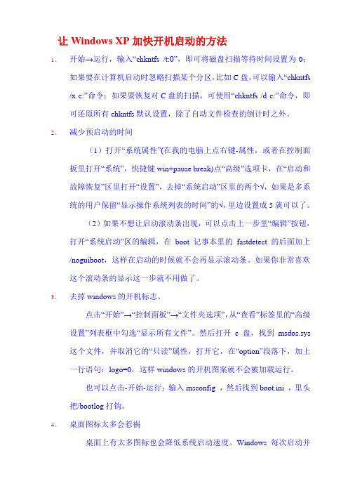
Windows启动流程及加速启动思路简述启动流程:定位引导设备→读取主引导记录→启动NTLDR→读取boot.ini→加载多重启动菜单→加载系统服务→帐户登录→加载注册表自启动程序→加载桌面→开始使用1.定位引导设备通过从硬盘启动提速:在Bios中可以设置从哪个硬件设备启动,设置从硬盘启动速度较快。
对于有软驱的电脑,应进入Bios取消启动时软驱的检查;对于没有软驱的台式机,建议进入Bios检查是否有从软驱启动的项,如有则取消。
不同的电脑(包括笔记本与台式、不同品牌的电脑)进入Bios的方法不同,操作界面也不同,为了更方便的操作,可以先查清自己Bios的型号,再上网寻找对应的操作手则(对新手很重要)。
2. 读取主引导记录(系统预读,表现在开机滚动条的滚动次数)通过取消该项提速:【开始→运行→键入”regedit”→HKEY-LOCAL-MACHINE/SYSTEM/CurrentContralset/Control/Session Manager/Memory Management/PrefetchParamentrs\\EnablePrefecher→键值设为”0”】键值意义说明:[0]取消预读功能;[1]只预读应用程序(安装很多软件的用户建议不要使用);[2] 只预读系统文件;[3] 预读系统文件和应用软件;如果选择预读系统文件,可以减少不必要的字体文件加快预读,字体文件占用系统资源多,引导时很慢,并且占用硬盘空间也不少。
因此尽量减少不必要的字体文件。
但如果删错了字体文件,搞不好会使Windows不正常。
因此可以采用下面这个“偷梁换柱”的方法(可以实现字体文件的安装,而不占用大量的磁盘空间):首先打开字库活页夹(如f:\zk),选中全部truetype字体文件,用鼠标的右键将它们拖动到c:\Windows\fonts活页夹中,在弹出的菜单中选择“在当前位置创建快捷方式”,这样就可以在系统的字体活页夹下建立字库文件的快捷方式了。
刀削客目前正在制作一款红色仿QQ 音速皮肤,所以将一点心得公布出来,方便其他网友尤其是新人参考。
在制作皮肤之前我们需要准备一下必要的东西:1,其它网友的皮肤,方便我们学习和修改,练习。
2.画图,或某种图片编辑工具,我曾经有过一款国人产的画图,可惜找不到了。
3.截图工具,个人使用的是这个。
4.玩转颜色,几乎是必备,获得MarkColor 等。
(在初期可以不用)。
5.图标工具,制作ICO 文件,例如Articons。
说明:有些皮肤的图片,您会发现用看图软件是无法打开的,这是因为它们是加密过的。
这些皮肤文件有些是可有可无的。
作为菜鸟,首先从修改其它人的皮肤开始,你可以进入音速启动所在目录,找到Skin 目录,打开任何一款皮肤的目录,也可以打开我提供的皮肤文件夹中的任意一款皮肤,大致看到一款皮肤所需要的图片。
让我们先按照名称来先排列一下顺序,我以LiveMessenger 皮肤为例。
第一个是Bar.bmp,这个是必须的,它对应着栏目的横条。
上边的是普通状态,下面的是当鼠标移过去时的状态,我们用画图修改一下,打开我提供的修改文件,找到Bar.bmp,覆盖替换一下,查看效果。
它的规格是bmp,40×40接下来是C_Normal.ico,C_Move.ico,C_Down.ico 按钮,它们代表着类别按钮的普通、移上、按下状态。
规格是ico,大小不定。
然后是Close_Normal.bmp,Close_Move.bmp ,Close_Down.bmp 同样的还有Min_..,Skin_...,然后是关闭、最小化、皮肤按钮的普通、移上、按下状态,规格是bmp,不定。
关闭是close,最小化是min,皮肤是skin。
然后是MenuCheck.ico,代表菜单中打勾的图片,规格是ico,16×16。
接着是MenuLeft.bmp,它代表菜单中左边图标背景图片,程序会自动拉长以适应菜单高度。
该背景可以是普通颜色,也可以是渐变颜色。
自动挡车弹射起步方法
自动挡车的弹射起步方法如下:
1. 将车辆放入自动挡位(位置通常为P或D)并踩住刹车踏板。
2. 将右脚移动到油门踏板上,轻轻踩下一点点。
3. 将左脚从刹车踏板上迅速移开。
4. 快速将脚从踩住的油门踏板上迅速松开。
5. 观察发动机转速表(仪表盘上的转速表),当发动机转速(RPM)达到理想的起步转速时(通常为2000-2500RPM),迅速放开刹车踏板。
6. 车辆会迅速弹射向前起步。
同时,应注意保持对车辆的控制,确保稳定前行。
注意事项:
- 在进行弹射起步时要确保周围的道路条件安全,确保没有行人或其他车辆。
- 这种起步方式可能使车辆磨损加大,因此不建议频繁使用,仅在需要加速迅速起步时使用。
- 弹射起步需要一定的驾驶技巧和经验,新手驾驶者应谨慎操作。
软件安装管理器-音速启动(VStart) 5.0 **专用皮肤,简单皮肤
可以不用自己改ini文件那么麻烦。
直接在软件上点击就能完成。
支持绝对路径转相对路径。
使用方法:
解压软件包(压缩包只是音速软件,安装软件要自己收集)到U盘目录,如上图。
双击打开【软件安装.exe】
1、添加软件,在空白处点击鼠标右键,添加文件。
浏览到软件安装程序
2、批量改路径,
全选所有软件,右键,批量操作
修改路径,转为相对路径。
修改图标,转为相对路径。
这样不论U盘拿到哪都能用了。
3、关于创建分类,点左下方的分类按钮,弹出类别管理菜单,点新建
新建的分类里面还不能添加软件,在空白处双击鼠标,新建栏目,才能添加软件。
功能很强大,其他功能自己摸索吧。
下载地址:
/space/file/yxl2/-4e0a-4f20-5206-4eab/-8f6f-4e f6-5b89-88c5-7ba1-7406-5668-002d-97f3-901f-542f-52a8(VStart)_5.0.rar/ .page。
- QUICK START GUIDE -MixPre-3 Audio Recorder | Mixer | USB Interfaceand more.Musicians • Singer/Song Writer• Live Performance • Music RecitalsVideographers• Audio for DSLRsField Recording• Interviews / Podcasts• Corporate Meetings• Nature Recording2MIXPRE-3Call Support1-608-524-0625 ingMIXPRE-34. Reattach battery sled.Back PanelRelease TabBattery SledSD Card Slot4MixPre-3 Left PanelY-cable USB-C to USB-A▶Connect a USB-C to USB-C cable to the MixPre-3 and a USB-C power source.To power the MixPre-3 from an AC wall outlet:▶Connect the MX-Charge external USB-C Wall Adapter accessory to the USB-C port on the MixPre-3 and an electrical outlet.Power SwitchMX-ChargeTo power on your MixPre-3:▶Slide the Power switch—located on the left panel—to ON.5QUICK START GUIDE3. Tap M4. Tap CCurrent File NamePower Status Icon Menu IconSD Card Remaining Record Time Current Headphone PresetTime CounterFile List Icon Meter ViewStatus BarF EATUrE d EscrIpTIoNFile List icon Tap this icon to view the list of recorded files.Current file name The name of the current file appears red when recording and green when playing.Power status icon Displays an icon representing type of power source (USB or battery); the battery icon also indicates the current batteries’ remaining power level.Menu icon Tap this icon to access the main Menu screen. When displaying menus, this icon changes to the Home icon.Meter view The stereo meter view shows the left and right mix channelsStatus barTap the status bar to toggle through three views of information that includes date and time, current headphone preset, remaining record time, sample rate and bit depth.Time counterDisplays elapsed time or timecode, which is stamped on each recorded file and can help simplify audio-to-video synchronization during post-production editing..[There are three pages of Menu settings, as indicated by dots. The solid black dot de-notes which page is displayed.]3. Tap Menu (dots) to view the 2nd page of settings.Page 1Page 24. Tap Card > Edit > Format.⚠This will erase all contents of the SD Card!5. When asked to confirm the command to format the card, tap OK.The status bar displays the SD card’s remaining record time, which will vary based on the storage capacity of the card being used. Other variables that affect digital recording times include concurrent audio track count, sample rate, and bit depth. Here are some record time estimates for a 16 GB SD card.F orMAT & r ATE T rAcks r EcordINg T IMEMIXPRE-35. Connect HeadphonesTo connect headphones:▶Plug in the headphones cable to the headphone output located onthe right panel.⚠The MixPre-3 can drive headphones to very loud levels. Take carewhen attaching headphones and setting the headphone gain.To adjust headphone gain:HP Knob HP Outputon top era so thats, connectc In, which4. Connect an Audio SourceThe MixPre-3 provides versatile connectivity options for a wide variety of recording applications. Channels 1-3 can be sourced from the XLR in-puts, the Aux/Mic Input, or USB 1-2 inputs.To connect an audio source:▶Using a standard XLR cable, connect an audio source to any of three XLR inputs—#1 and 2 on the left panel, #3 on the right panel. ▶Plug a USB audio source into the USB-C port on the MixPre-3.▶Plug an unbalanced line or plug-in-power (PIP) mic audio source into the Aux/Mic In 3.5 mm TRS connection.Aux/Mic In on Right PanelXLR Inputs #1 & #2Left Panel8LCD Press the rotary knobs for the chosen channel. The Channel SettingsThe Channel Settings screen appears differently depending on the System >ChannelKnobs2. Tap Input and select from one of the following input types:I NpUT T YpEs d EscrIpTIoNMic Use for microphones. For condenser mics requiring 48v phantom power, set Phantom to On. Line Use for balanced analog line level sources.Aux In 1,2Use for unbalanced stereo input.LED Rings8. Connect Timecode Input (Optional)The MixPre-3 has an internal Time-of-Day clock that can be used for timecode, but an external source for timecode may also be used via HDMI or the Aux/Mic In 3.5 mm connection on the MixPre-3’s right side panel. The Aux/Mic In port provides two unbalanced channels through which to receive timecode.To connect timecode:1. Connect a timecode source to appropriate port. For instance, connect an externaltimecode, connect the HDMI out from the camera to the HDMI TC In port on the MixPre-3. Right Panel2. Tap .3. Select Inputs > Aux In Mode, and then select Timecode.4. Select Timecode > Mode. Options include: Off, Aux In 1, Aux In 2, and HDMI TC In.MIXPRE-310hree channel the MixPre-3. There are three illuminated transport controls on the front panel of the MixPre-3 for recordingRecording may also be triggered from rolling timecode or from compatible.Select Record > Rec Trigger. Options include: Off, HDMI flag, and Timecode.TransportControlsMIXPRE-3 12QUICK START GUIDE133. (OptioTo monitor return from the camera, connect the camera’s analog audio output to the 3.5 mm Aux/Mic In on the MixPre-3, and set Inputs > Aux In Mode to Return.QUICK START GUIDE tripod and camera, attach it to the bottom of the camera first before screwing it into place Allen Wrench & Anti-rotation PinMixPre-3 Back Panel3. (Optional) If your camera has a slot for the anti-rotation pin, screw the pin into place on topof the MixPre-3, and then position the MixPre-3 against the bottom of the camera so that the pin fits into the camera’s slot.The anti-rotation pin may also be screwed into a tripod and slotted into thebottom of the MixPre-3.4. From the MixPre-3’s bottom panel, insert the Allen wrench into themounting screw hole and push up on the retractable screw. Rotate Retractable ScrewThreaded hole for Anti-rotation Pin15with mobileanel of thee MixPre-3.anel of theTap .Tap System > Bluetooth. Options include Off and On.This Declaration of Conformity applies to the above-listed product(s) placed on the EU marketMatt Anderson - Sound Devices, LLC President19QUICK START GUIDEwww.sound Part # 7375.003。
音速启动使用教程
点这里下载==》 音速启动(VStart) v5.0 Build 2009.03.04
很多人都有这样的困惑,就是当安装的软件越来越多的时候,您会发现程序的快捷图标逐渐侵占了系统桌面的大部分区域,这不仅影响了桌面的美观,而且影响工作效率,试想在众多的桌面快捷图标中立刻找到需要运行的程序可真不是件容易的事情。
庞杂的桌面
今天小编为大家推荐一款可以解放我们的桌面的实用精品小软件——音速启动,可能你看到它的第一眼会以为它是QQ ,可是它却是一个实实在在的程序管理软件,桌面上所有的程序、文件、文件夹甚至是网页都可以拖拽到它的控制面板内,用户可以分门别类进行管理,更有效率的启动程序。
它拥有与QQ 一样精致的界面,并且可以像QQ 一样自动隐藏在桌面顶部,隐藏后的桌面将是无比的清爽!
清爽的桌面音速启动可以帮助用户实现以下功能:
点击此处下载音速启动软件资料:
测评环境:
一、界面篇
音速启动是绿色软件,因此用户只需将下载得到的软件安装包直接解压缩后即可运行,无需安装,绿色环保。
建议将音速启动放在非系统盘,以免重装系统后数据丢失。
音速启动采用超仿真QQ界面的形式,并且可以像QQ一样自动隐藏在桌面顶部边缘,从而不影响桌面美观。
默认界面上已经集成了多个系统工具的快捷方式,比如我的电脑、我的文档以及回收站等。
软件上方为时间日期的显示,左上角则为当前地区的天气情况预报;左侧则为具体的项目栏。
软件下方则是设置以及菜单选项。
界面较为直观,第一眼看去便可以知晓其中大概情况。
默认界面
程序默认分为三个模块,分别是“我的程序”、“我的文件夹”以及“网址”,分别可以用来管理常用程序、文件/文件夹以及常用网址等,用户可以通过单击界面左侧的三个控制按钮依次切换各个分组模块。
音速启动支持换肤功能,用户只需点击界面右上角的“+”号按钮,可以轻松的实现换肤操作,如图所示,音速启动提供了七款本地皮肤供用户换用,此外程序还支持网上皮肤和论坛皮肤的下载和切换,完全可以满足不同用户的多样化需求
七款本地皮肤
音速启动除了提供换肤功能外,还提供了实用的外观设定功能,用户可以自由DIY皮肤颜色、透明度、背景等参数,如图所示,进一步增添了用户的使用乐趣。
外观设定选项
二、功能篇
音速启动作为一款国产桌面软件新宠,不仅仅起到美化桌面的作用,更重要的是该软件可以将用户常用的文件、文件夹、应用程序、网址等以分组的形式添加到程序操作界面中,相当于把桌面快捷方式、开始菜单项、我的电脑、控制面板等放在一起集中管理,大幅度减少了各个界面的切换频率,提高了系统的使用效率。
音速启动默认提供了“我的程序”、“我的文件夹”以及“网址”三个类别,每个类别用于添加相应的程序,比如“我的程序”模块可以用于添加常用的应用程序,“我的文件夹”模块可以用于添加常用的文件或者文件夹,“网址”模块可以用于添加常用网址。
另外,用户还可以自由增加新的类别或者删除已有类别,如图所示,除了新建类别,音速启动还支持对类别的删除、改名、加密、上移和下移操作。
添加类别
在同一类别,用户可以添加不同的“栏目”。
同一个类别中可以添加有多个栏目,这样,用户就可以将添加到音速启动的程序进行细化,分门别类进行管理,方便用户使用。
程序不仅支持添加普通栏目,还支持添加文件夹/网址栏目,如图所示。
添加栏目
下图所示为小编将“我的程序”类别划分为包括“常用软件”、“安全软件”、“办公软件”、“装机软件”、“系统清理”等栏目,如图所示。
同一类别可以细化有多个栏目
向音速启动程序中添加快捷方式,最简单的方法就是通过鼠标左键直接拖拽到对应的类别下的具体栏目。
另外,用户可以通过右键单击音速启动主界面的空白列表区域,在弹出的右键菜单中选择添加文字、目录、超链接、系统功能等,如图
所示。
右键添加选项
用户可以在“添加系统功能”窗口简单快速的添加系统功能,程序提供的系统功能包括系统链接、系统操作、音量控制等多个方面,很多系统功能用户通过直接拖拽的方式直接添加可能有点困难,而在“添加系统功能”窗口中则可以很快很轻松的进行添加,如图所示。
音速启动使用教程(2)
添加系统功能添加自动登录功能是新版音速启动新增的一个重要功能,目前程序支持自动登录网站和自动登录QQ2008,尤其是自动登录QQ功能非常实用,用户输入自己的QQ号码和密码后单击确定按钮会在音速启动面板上生成一
添加系统功能
添加自动登录功能是新版音速启动新增的一个重要功能,目前程序支持自动登录网站和自动登录QQ2008,尤其是自动登录QQ 功能非常实用,用户输入自己的QQ 号码和密码后单击确定按钮会在音速启动面板上生成一个能自动登录该QQ 快捷方式,以后用户登录QQ 时直接单击这个快捷图标即可直接登录QQ ,而不需要每次都输入QQ 号码和密码了。
添加自动登录
对于添加进列表中的程序快捷方式,用户可以将其删除、剪切、复制等操作,另外,用户还可以对其设置热键,设置计划任务等,如图所示。
选择操作
自定义启动热键
自定义计划任务
音速启动除了具有强大的管理功能外,还附带了多种实用的功能插件,比如天气预报、文件夹保护、壁纸随意换等等,增加了用户使用电脑的乐趣,更加便利了人们的生活,如图所示。
天气预报功能可以具体到县级城市,并且可以预报今明后三天的天气,非常实用,如图所示。
天气预报
文件夹保护功能支持用户为指定文件夹设置保护口令,起到隐私保护的作用,如图所示,该功能需要用户手动激活。
文件夹保护
音速启动提供了“万年历”,相信这个经典实用小工具绝对是众多用户不可或缺的必备工具,如图所示。
万年历
音速启动提供了邮件检测功能,用户设定好邮件检测时间和新邮件提醒方式,就不用担心错过重要邮件了,该功能不要用户手动开启并进行一些绑定配置。
邮件检测
三、资源篇
作为一款桌面工具,如果消耗系统资源过大,即使其功能再完美,也无法立足,而音速启动在提供强大程序辅助管理功能的前提下,实际占用内存资源不足2M,占用虚拟内存不足4M,资源占用方面表现的相当出色。
资源占用
总结:
音速启动在美化桌面的同时都能够帮助用户高效的管理应用程序、文件、文件夹甚至网址等几乎所有的可执行程序,至于其在桌面上的具体呈现形式以及具体管理哪些可执行程序完全由用户自行掌握,相信使用音速启动,定会净化并美化您的桌面,让您的数字生活更高效更便捷!各位为桌面程序越来越多烦恼的朋友们,赶快下载试用音速启动吧,相信它一定会能够还您清爽桌面!。