机械毕业设计英文外文翻译201混凝土运输车中液压泵压力的影响 (2)
- 格式:docx
- 大小:114.19 KB
- 文档页数:13

译文原文:Understanding of concrete pump hydraulic systemItalian CIFA Concrete Machinery Company(1.CIFA concrete mechanical pump Institute, Italy)Pumping Hydraulic systemBoom hydraulic systemOutrigger hydraulic systemHydraulic system diagramDaily check and maintenance of the hydraulic systemThe functions of the truck mounted concrete pump, hydraulic system can be divided into pumping hydraulic system, boom hydraulic system, outrigger hydraulic system.Pumping Hydraulic system Is divided into three parts: main pumping system, distribution and lubricating system, mixing and cooling and cleaning system.Main pumping systemThere are two hydraulic loops: open and close loop.The Open loop: uses an A11VLO190 variable displacement of axial piston pump. It is fitted with a constant power control device, pressure cut-off valve and electricalstroke limiter with proportional solenoid. The constant power control device has been set in the factory. The displacement can be adjusted from 0 to Maximum by turning the oil pump displacement potentiometer on the control panel from low to high.Fig. 1 A11VLO 190A,B Service port (without charging pump) 420 barS Suction port (with charging pump) 35 barT1, T2 Air bleed, tankR Air bleed, oil drainM1 Measuring point, regulating chamberM Measuring point, service portG Port for positioning pressure (controller) for version with stroke limiter (H.., U2), HD and EP with screw ed fitting GE10 – PLM (otherwise port G closed)The other is the control line, which can change the flow direction and the displacement of main pump through constant power valve, proportional solenoid pressure reducing valve, directional control valve and servo valve of main pump.The Closed loop: There is an auxiliary pump with relief valve that the setting pressure is 3.5Mpa in A4VG180. The auxiliary pump has two output ways. One is the charge oil line, which connects with suction line of main pump through the check valve in two pressure relief valves and add oil to main pump. At the same time excessive hydraulic oil return to oil tank through flushing valve and cooler to realize heat exchange for closed loop.A, B Service line ports SAE 1 1/4", high pressure series 420 barT1 Case drain or filling portT2 Case drain M33×2; 18 deepM A, M B Pressure gauge - operating pressure A, BR Air bleedS Boost suction portX1, X2Control pressure ports (before the orifice)G Pressure port for auxiliary circuitP S Control pressure supplyFa Filter outletFa1Filter outlet (filter assembly)Fe Filter inlet M33×2; 18 deepF S Port from filter to suction line (cold start)M H Port for balanced high pressureY1, Y2Remote control ports (only for HD control)Flushing valveUsed for closed loop to prevent excessive heat build-up in closed circuit operation. The setting pressure of flushing valve is 3.0MPaPressure reducing valve with proportional solenoidUsed for closed loop. The Output pressure is connected with the remote control port of main pump to control the displacement and is controlled by a proportional current signal and constant power valve. The displacement can be adjusted from 0 to Maximum by turning the displacement adjusting potentiometer.Constant power valveUsed for closed loop. When the hydraulic system pressure is over the setting pressure, the valve works to reduce the output pressure of the pressure reducing valve and maintain the constant power.Pilot pressure setting Power settingFig.3 Constant power valveMain pump suction filterOpen loop: filtration fineness 100u.Close loop: filtration fineness 20u.When the indicator in the vacuum gauge exceeds the safe area or the electric signal instrument gives a warning, the cartridge may be blocked. It should be clean or replace filter cartridge promptly.Filter filtration fineness is 20u in open loop. When the reading pressure of the vacuum gauge exceeds 0.35Mpa, the cartridge may be blocked. It should be clean orReturn filterreplace filter cartridge promptly.Filter filtration fineness is 10u in closed loop. When the electricity deliver reports to the police, the cartridge may be blocked, it should be clean or replace filter cartridge promptly. Distribution and lubricating systemConstant pressure pumpSetting screw for pressurecontrol zero /Stroke pressureFig.4 Constant pressure pumpAn A10VO28 constant pump is used for the distribution system of supply oil.The setting of the pressure control valve of the pump is 16Mpa. Once the system pressure is reached,the bump will keep this pressure then decrease the displacement. There is a pressure relief valve in the distribution circuit to act as a safety valve, which is set to 18Mpa.Plate ball valve (shut-off valve)Used to discharge the accumulator. It must be rotated the lever of shut-off valve anti-clockwise when the pumping finishes or stopped for maintenance, in order to discharge the pressure of theaccumulator. (Pressure gauge of distribution system is zero) AccumulatorInflation pressure is 8-9Mpa. Use Only Nitrogen to fill the accumulator. Charging pressure should not exceed these figures.Lubricating systemThere are two types. One is reciprocating centralized lubrication that is driven by oil from the swing cylinders of distribution system includes lubricating single pump (or double pump), distributor, damper and filter. The other is automatic centralized lubrication that is driven by a D.C motor with an independent grease tank and independent from the hydraulic system. The interval time of lubrication is carried out in the factory. The lubrication system works automatically when pumping.Mixing, cooling, cleaning systemOnly the Mixing, cooling, cleaning system are driven by motor in open loop.Gear pumpGear pump supplies oil to the mixing, cooling, cleaning system.Sandwich type relief valveThe pressure is set to 14Mpa.Ressure relayIf the mixing blade is stuck, the system pressure will raise. When the pressure exceeds the setting value (usually 10Mpa), the pressure relay will give a warning. The Solenoid directional control valve changes direction to let the mixing motor to rotate anti-clockwise. After 6 second the solenoid valve will reset, and the mixing motor will rotate clockwise again. Return filterThe filtration fineness is 10u in closed loop. The cartridge may be blocked when the electric alarm sounds. It should be replace promptly.Boom hydraulic systemBoom pumpBoom and outrigger use the same pump.37m and 40m truck mounted concrete pumps: A2FO23 fixed displacement pump44m and 47m truck mounted concrete pumps: A7VO55LRDS variable displacement pump, or A7VO55DRS variable displacement pump46m and 49m truck mounted concrete pumps: A7VO55LRDS variable displacement pumpFig.5 A7VO55DRS Fig.6 A7VO55LRDS Fig.7 A2FO23 Boom proportional directional spool valveThe proportional directional spool valve with electro-hydraulic consists of pressure relief valve, pressure reducing valve, and flow control valve, and can becontrolled manual or by remote control.Fig.8 Boom proportional directional spool valveLoad-holding valveLoad-holding valve has three functions. (1) It acts as a lock when the cylinder isn’t moving. (2) Load-holding valve has twice relief function to protect boom against vibrating. It will be adjusted in the factory. (3) When the boom moves downward asSlewing load-holding valvegravity load, it can limit speed to prevent the boom falling too quickly and shaking.There are three main functions. Lock, overload protection and speed limiting. Outrigger hydraulic systemOutrigger hydraulic system and boom hydraulic system are used the same pump to supply oil. Outriggers should be set up before the boom is operated by the control levers or electric control button on both sides of the truck mounted concrete pump.Outrigger proportional directional spool valveIt is an integrated unit with a relief valve inside to control maximum pressure of the outrigger hydraulic system.Fig .9 Outrigger proportional directional spool valveOutrigger hydraulic lockIt is used to lock the outrigger cylinders and pay attention to the vertical moving of the outrigger cylinder when working .Pressure relief valve中文译文:混凝土泵车液压系统的认识意大利 CIFA 混凝土机械公司(1.CIFA 混凝土机械泵车研究所, 意大利,)泵送单元液压系统臂架液压系统 支腿液压系统 液压原理图液压系统的日常保养及维护泵车液压系统按泵车功能可划分为泵送单元液压系统、臂架液压系统、支腿液压系统。

Friction , Lubrication of BearingIn many of the problem thus far , the student has been asked to disregard or neglect friction . A ctually , friction is present to some degree whenever two parts are in contact and move on each other. The term friction refers to the resistance of two or more parts to movement.Friction is harmful or valuable depending upon where it occurs. friction is necessary for fastening devices such as screws and rivets which depend upon friction to hold the fastener and the parts together. Belt drivers, brakes, and tires are additional applications where friction is necessary.The friction of moving parts in a machine is harmful because it reduces the mechanical advantage of the device. The heat produced by friction is lost energy because no work takes place. A lso , greater power is required to overcome the increased friction. Heat is destructive in that it causes expansion. Expansion may cause a bearing or sliding surface to fit tighter. If a great enough pressure builds up because made from low temperature materials may melt.There are three types of friction which must be overcome in moving parts: (1)starting, (2)sliding,and(3)rolling. Starting friction is the friction between two solids that tend to resist movement. When two parts are at a state of rest, the surface irregularities of both parts tend to interlock and form a wedging action. T o produce motion in these parts, the wedge-shaped peaks and valleys of the stationary surfaces must be made to slide out and over each other. The rougher the two surfaces, the greater is starting friction resulting from their movement .Since there is usually no fixed pattern between the peaks and valleys of two mating parts, the irregularities do not interlock once the parts are in motion but slide over each other. The friction of the two surfaces is known as sliding friction. A s shown in figure ,starting friction is always greater than sliding friction .Rolling friction occurs when roller devces are subjected to tremendous stress which cause the parts to change shape or deform. Under these conditions, the material in front of a roller tends to pile up and forces the object to roll slightly uphill. This changing of shape , known as deformation, causes a movement of molecules. As a result ,heat is produced from the added energy required to keep the parts turning and overcome friction.The friction caused by the wedging action of surface irregularities can be overcome partly by the precision machining of the surfaces. However, even these smooth surfaces may require the use of a substance between them to reduce the friction still more. This substance is usually a lubricant which provides a fine, thin oil film. The film keeps the surfaces apart and prevents the cohesive forces of the surfaces from coming in close contact and producing heat .Another way to reduce friction is to use different materials for the bearing surfaces and rotating parts. This explains why bronze bearings, soft alloy s, and copper and tin iolite bearings are used with both soft andhardened steel shaft. The iolite bearing is porous. Thus, when the bearing is dipped in oil, capillary action carries the oil through the spaces of the bearing. This type of bearing carries its own lubricant to the points where the pressures are the greatest.Moving parts are lubricated to reduce friction, wear, and heat. The most commonly used lubricants are oils, greases, and graphite compounds. Each lubricant serves a different purpose. The conditions under which two moving surfaces are to work determine the type of lubricant to be used and the system selected for distributing the lubricant.On slow moving parts with a minimum of pressure, an oil groove is usually sufficient to distribute the required quantity of lubricant to the surfaces moving on each other .A second common method of lubrication is the splash system in which parts moving in a reservoir of lubricant pick up sufficient oil which is then distributed to all moving parts during each cycle. This system is used in the crankcase of lawn-mower engines to lubricate the crankshaft, connecting rod ,and parts of the piston.A lubrication system commonly used in industrial plants is the pressure system. In this system, a pump on a machine carries the lubricant to all of the bearing surfaces at a constant rate and quantity.There are numerous other sy stems of lubrication and a considerable number of lubricants available for any given set of operating conditions. Modern industry pays greater attention to the use of the proper lubricants than at previous time because of the increased speeds, pressures, and operating demands placed on equipment and devices.Although one of the main purposes of lubrication is reduce friction, any substance-liquid , solid , or gaseous-capable of controlling friction and wear between sliding surfaces can be classed as a lubricant.V arieties of lubricationUnlubricated sliding. Metals that have been carefully treated to remove all foreign materials seize and weld to one another when slid together. In the absence of such a high degree of cleanliness, adsorbed gases, water vapor ,oxides, and contaminants reduce frictio9n and the tendency to seize but usually result in severe wear。
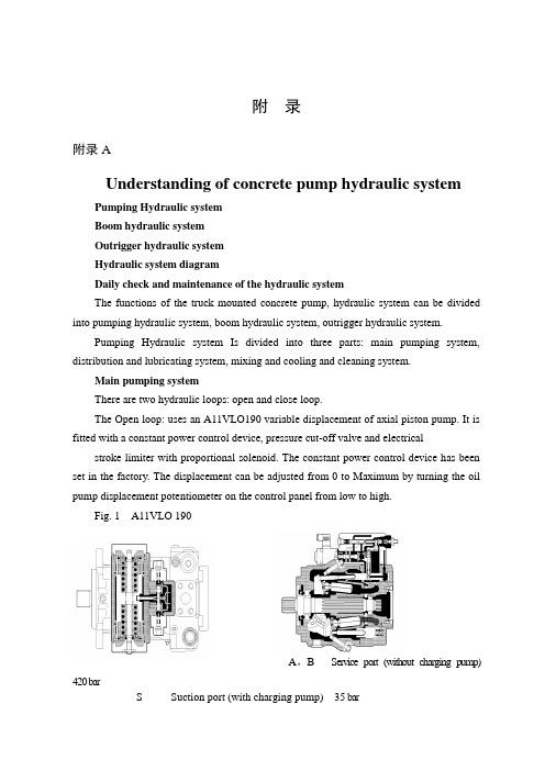
附录附录AUnderstanding of concrete pump hydraulic systemPumping Hydraulic systemBoom hydraulic systemOutrigger hydraulic systemHydraulic system diagramDaily check and maintenance of the hydraulic systemThe functions of the truck mounted concrete pump, hydraulic system can be divided into pumping hydraulic system, boom hydraulic system, outrigger hydraulic system.Pumping Hydraulic system Is divided into three parts: main pumping system, distribution and lubricating system, mixing and cooling and cleaning system.Main pumping systemThere are two hydraulic loops: open and close loop.The Open loop: uses an A11VLO190 variable displacement of axial piston pump. It is fitted with a constant power control device, pressure cut-off valve and electrical stroke limiter with proportional solenoid. The constant power control device has beenset in the factory. The displacement can be adjusted from 0 to Maximum by turning the oil pump displacement potentiometer on the control panel from low to high.Fig. 1 A11VLO 190A,B Service port (without charging pump) 420 barS Suction port (with charging pump) 35 barT1, T2 Air bleed, tankR Air bleed, oil drainM1 Measuring point, regulating chamberM Measuring point, service portG Port for positioning pressure (controller) for version with stroke limiter (H.., U2), HD and EP with screwed fitting GE10 – PLM (otherwise port G closed)The other is the control line, which can change the flow direction and the displacement of main pump through constant power valve, proportional solenoid pressure reducing valve, directional control valve and servo valve of main pump.The Closed loop: There is an auxiliary pump with relief valve that the setting pressure is 3.5Mpa in A4VG180. The auxiliary pump has two output ways. One is the charge oil line, which connects with suction line of main pump through the check valve in two pressure relief valves and add oil to main pump. At the same time excessive hydraulic oil return to oil tank through flushing valve and cooler to realize heat exchange for closed loop.A, B Service line ports SAE 1 1/4", high pressure series 420 barT1 Case drain or filling portT2 Case drain M33×2; 18 deepM A, M B Pressure gauge - operating pressure A, BR Air bleedS Boost suction portX1, X2Control pressure ports (before the orifice)G Pressure port for auxiliary circuitP S Control pressure supplyFa Filter outletFa1Filter outlet (filter assembly)Fe Filter inlet M33×2; 18 deepF S Port from filter to suction line (cold start)M H Port for balanced high pressureY1, Y2Remote control ports (only for HD control)Flushing valveUsed for closed loop to prevent excessive heat build-up in closed circuit operation. The setting pressure of flushing valve is 3.0MPaPressure reducing valve with proportional solenoidUsed for closed loop. The Output pressure is connected with the remote control port of main pump to control the displacement and is controlled by a proportional current signal and constant power valve. The displacement can be adjusted from 0 to Maximum by turning the displacement adjusting potentiometer.Constant power valveUsed for closed loop. When the hydraulic system pressure is over the setting pressure, the valve works to reduce the output pressure of the pressure reducing valve and maintain the constant power.Fig.3 Constant power valveMain pump suction filterOpen loop: filtration fineness 100u.Close loop: filtration fineness 20u.When the indicator in the vacuum gauge exceeds the safe area or the electric signal instrument gives a warning, the cartridge may be blocked. It should be clean or replace filter cartridge promptly.Filter filtration fineness is 20u in open loop. When the reading pressure of the vacuum gauge exceeds 0.35Mpa, the cartridge may be blocked. It should be clean or Return filterreplace filter cartridge promptly.Filter filtration fineness is 10u in closed loop. When the electricity deliver reports to the police, the cartridge may be blocked, it should be clean or replace filter cartridge promptly.Distribution and lubricating systemConstant pressure pumpFig.4 Constant pressure pumpAn A10VO28 constant pump is used for the distribution system of supply oil.The setting of the pressure control valve of the pump is 16Mpa. Once the system pressure is reached, the bump will keep this pressure then decrease the displacement. Thereis a pressure relief valve in the distribution circuit to act as a safety valve, which is set to 18Mpa.Plate ball valve (shut-off valve)Used to discharge the accumulator. It must be rotated the lever of shut-off valve anti-clockwise when the pumping finishes or stopped for maintenance, in order to discharge the pressure of theaccumulator. (Pressure gauge of distribution system is zero) AccumulatorInflation pressure is 8-9Mpa. Use Only Nitrogen to fill the accumulator. Charging pressure should not exceed these figures.Lubricating systemThere are two types. One is reciprocating centralized lubrication that is driven by oil from the swing cylinders of distribution system includes lubricating single pump (or double pump), distributor, damper and filter. The other is automatic centralized lubrication that is driven by a D.C motor with an independent grease tank and independent from the hydraulic system. The interval time of lubrication is carried out in the factory. The lubrication system works automatically when pumping.Mixing, cooling, cleaning systemOnly the Mixing, cooling, cleaning system are driven by motor in open loop.Gear pumpGear pump supplies oil to the mixing, cooling, cleaning system.Sandwich type relief valveThe pressure is set to 14Mpa.Ressure relayIf the mixing blade is stuck, the system pressure will raise. When the pressure exceeds the setting value (usually 10Mpa), the pressure relay will give a warning. The Solenoid directional control valve changes direction to let the mixing motor to rotate anti-clockwise. After 6 second the solenoid valve will reset, and the mixing motor will rotate clockwise again.Return filterThe filtration fineness is 10u in closed loop. The cartridge may be blocked when the electric alarm sounds. It should be replace promptly.Boom hydraulic systemBoom pumpBoom and outrigger use the same pump.37m and 40m truck mounted concrete pumps: A2FO23 fixed displacement pump44m and 47m truck mounted concrete pumps: A7VO55LRDS variable displacement pump, or A7VO55DRS variable displacement pump46m and 49m truck mounted concrete pumps: A7VO55LRDS variable displacement pumpFig.5 A7VO55DRS Fig.6 A7VO55LRDS Fig.7 A2FO23Boom proportional directional spool valveThe proportional directional spool valve with electro-hydraulic consists of pressure relief valve, pressure reducing valve, and flow control valve, and can becontrolled manual or by remote control.Fig.8 Boom proportional directional spool valveLoad-holding valveLoad-holding valve has thre e functions. (1) It acts as a lock when the cylinder isn’t moving. (2) Load-holding valve has twice relief function to protect boom against vibrating. It will be adjusted in the factory. (3) When the boom moves downward asSlewing load-holding valvegravity load, it can limit speed to prevent the boom falling too quickly and shaking.There are three main functions. Lock, overload protection and speed limiting.Outrigger hydraulic systemOutrigger hydraulic system and boom hydraulic system are used the same pump to supply oil. Outriggers should be set up before the boom is operated by the control levers or electric control button on both sides of the truck mounted concrete pump.Outrigger proportional directional spool valveIt is an integrated unit with a relief valve inside to control maximum pressure of theoutrigger hydraulic system.Fig .9 Outrigger proportional directional spool valveOutrigger hydraulic lockIt is used to lock the outrigger cylinders and pay attention to the vertical moving of the outrigger cylinder when working .Pressurerelief附录B混凝土泵车液压系统的认识泵送单元液压系统 臂架液压系统 支腿液压系统 液压原理图液压系统的日常保养及维护泵车液压系统按泵车功能可划分为泵送单元液压系统、臂架液压系统、支腿液压系统。

液压机械与液压泵外文翻译文献液压机械与液压泵外文翻译文献(文档含中英文对照即英文原文和中文翻译)Hydraulic machinery and pumpHydraulic machinery are machines and tools which use fluid power to do work. Heavy equipment is a common example.In this type of machine, high-pressure liquid - called hydraulic fluid - is transmitted throughout the machine to various hydraulic motors and hydraulic cylinders. The fluid is controlled directly or automatically by control valves and distributed through hoses and tubes.The popularity of hydraulic machinery is due to the very large amount ofpower that can be transferred through small tubes and flexible hoses, and the high power density and wide array of actuators that can make use of this power.Hydraulic machinery is operated by the use of hydraulics, where a liquid is the powering medium. Pneumatics, on the other side, is based on the use of a gas as the medium for power transmission, generation and control.Hydraulic circuitsFor the hydraulic fluid to do work, it must flow to the actuator and or motors, then return to a reservoir.The fluid is then filtered and re-pumped. The path taken by hydraulic fluid is called a hydraulic circuit of which there are several types. Open center circuits use pumps which supply a continuous flow. The flow is returned to tank through the control valve's open center; that is, when the control valve is centered, it provides an open return path to tank and the fluid is not pumped to a high pressure. Otherwise, if the control valve is actuated it routes fluid to and from an actuator and tank. The fluid's pressure will rise to meet any resistance, since the pump has a constant output. If the pressure rises too high, fluid returns to tank through a pressure relief valve.Hydraulic pumps supply fluid to the components in the system. Pressure in the system develops in reaction to the load. Hence,a pump rated for 5,000 psi is capable of maintaining flow against a load of 5,000 psi.Pumps have a power density about ten times greater than an electric motor (by volume). They are powered by an electric motor or an engine, connected through gears, belts, or a flexible elastomeric coupling to reduce vibration.Common types of hydraulic pumps to hydraulic machinery applications are;Gear pump: cheap, durable, simple. Less efficient, because they are constant displacement, and mainly suitable for pressures below 20 MPa (3000 psi).Vane pump: cheap and simple, reliable (especially in g-rotor form). Good for higher-flow low-pressure output.Axial piston pump: many designed with a variable displacement mechanism, to vary output flow for automatic control of pressure. There are various axial piston pump designs, including swashplate and checkball. The most common is the swashplate pump.Radial piston pump: A pump that is normally used for very high pressure at small flows.Piston pumps are more expensive than gear or vane pumps, but provide longer life operating at higher pressure, with difficult fluids and longer continuous duty cycles. Pistonpumps make up one half of a hydrostatic transmission. Control valvesDirectional control valves route the fluid to the desired actuator. They usually consist of a spool inside a cast iron or steel housing.Directional control valves are usually designed to be stackable, with one valve for each hydraulic cylinder, and one fluid input supplying all the valves in the stack.The spool position may be actuated by mechanical levers, hydraulic pilot pressure, or solenoids which push the spool left or right.The main valve block is usually a stack of off the shelf directional control valves chosen by flow capacity and performance. Some valves are designed to be proportional (flow rate proportional to valve position), while others may be simply on-off. The control valve is one of the most expensive and sensitive parts of a hydraulic circuit.Pressure relief valves are used in several places in hydraulic machinery; on the return circuit to maintain a small amount of pressure for brakes, pilot lines, etc... On hydraulic cylinders, to prevent overloading and hydraulic line rupture. On the hydraulic reservoir, to maintain a small positive pressurewhich excludes moisture and contamination.Pressure reducing valves reduce the supply pressure as needed for various circuits.Check valves are one-way valves, allowing an accumulator to charge and maintain its pressure after the machine is turned off, for example.Counterbalance valves are in fact a special type of pilot controlled check valve. Whereas the check valve is open or closed, the counterbalance valve acts a bit like a pilot controlled flow control.Hydraulic pump typesGear pumpsGear pumps (with external teeth) (fixed displacement) are simple and economical pumps. The swept volume or displacement of gear pumps for hydraulics will be between about 1 cm3(0.001 litre) and 200 cm3(0.2 litre). These pumps create pressure through the meshing of the gear teeth, which forces fluid around the gears to pressurize the outlet side. Some gear pumps can be quite noisy, compared to other types, but modern gear pumps are highly reliable and much quieter than older models.Rotary vane pumpsRotary vane pumps (fixed and simple adjustable displacement) have higher efficiencies than gear pumps, but are also used for mid pressures up to 180 bars in general. Some types of vane pumps can change the centre of the vane body, so that a simple adjustable pump is obtained. These adjustable vane pumps are in general constant pressure or constant power pumps: the displacement is increased until the required pressure or power is reached and subsequently the displacement or swept volume is decreased until an equilibrium is reached.Screw pumpsScrew pumps (fixed displacement) are a double Archimedes' screw, but closed. This means that two screws are used in one body. The pumps are used for high flows and relatively low pressure (max 100 bar). They were used on board ships where the constant pressure hydraulic system was going through the whole ship, especially for the control of ball valves, but also for the steering gear and help drive systems. The advantage of the screw pumps is the low sound level of these pumps; the efficiency is not that high.Bent axis pumpsBent axis pumps, axial piston pumps and motors using the bent axis principle, fixed or adjustable displacement, exists in two different basic designs. The Thoma-principle (engineer Hans Thoma, Germany, patent 1935) with max 25 degrees angle and the Wahlmark-principle (GunnarAxel Wahlmark, patent 1960) with spherical-shaped pistons in one piece with the piston rod, piston rings, and maximum 40 degrees between the driveshaft centerline and pistons (V olvo Hydraulics Co.). These have the best efficiency of all pumps. Although in general the largest displacements are approximately one litre per revolution, if necessary a two-liter swept volume pump can be built. Often variable-displacement pumps are used, so that the oil flow can be adjusted carefully. These pumps can in general work with a working pressure of up to 350–420 bars in continuous work.Axial piston pumps swashplate principleAxial piston pumps using the swashplate principle (fixed and adjustable displacement) have a quality that is almost the same as the bent axis model. They have the advantage of being more compact in design. The pumps are easier and more economical to manufacture; the disadvantage is that they are more sensitive to oil contamination.Radial piston pumpsRadial piston pumps (fixed displacement) are used especially for high pressure and relatively small flows. Pressures of up to 650 bar are normal. In fact variable displacement is not possible, but sometimes the pump is designed in such a way that the plungers can be switched off one by one, so that a sort of variable displacement pump is obtained.Peristaltic pumpsPeristaltic pumps are not generally used for high pressures.Pumps for open and closed systemsMost pumps are working in open systems. The pump draws oil from a reservoir at atmospheric pressure. It is very important that there is no cavitation at the suction side of the pump. For this reason the connection of the suction side of the pump is larger in diameter than the connection of the pressure side. In case of the use of multi-pump assemblies, the suction connection of the pump is often combined. It is preferred to have free flow to the pump (pressure at inlet of pump at least 0.8 bars). The body of the pump is often in open connection with the suction side of the pump.In case of a closed system, both sides of the pump can be at high pressure. The reservoir is often pressurized with 6-20 bars boost pressure. For closed loop systems, normally axial piston pumps are used. Because both sides are pressurized, the body of the pump needs a separate leakage connection.Multi pump assemblyIn a hydraulic installation, one pump can serve more cylinders and motors. The problem however is that in that case a constant pressure system is required and the system always needs the full power. It is more economic to give each cylinder and motor its own pump. In that case multi pump assemblies can be used. Gearpumps can often be obtained as multi pumps.The different chambers (sometimes of different size) are mounted in one body or built together. Also vane pumps can often be obtained as a multi pump. Gerotor pumps are often supplied as multi pumps. Screw pumps can be built together with a gear pump or a vane pump. Axial piston swashplate pumps can be built together with a second pump of the same or smaller size, or can be built together with one or more gear pumps or vane pumps (depending on the supplier). Axial plunger pumps of the bent axis design can not be built together with other pumps.翻译:液压机械及泵液压机械是机械和工具,它使用流体的力量去做的工作。
![毕业论文中英文文献翻译液压专业毕业论文[管理资料]](https://img.taocdn.com/s1/m/4105879e58fafab068dc020e.png)
本科毕业论文--外文原文学院(系):年级专业:液压学生姓名:指导教师:完成日期:Why decompression is necessary in hydraulic systemsHydraulics & PneumaticsJun. 11, 2008 12:00amWhy decompression is necessary in hydraulic systemsIn high-pressure circuits with large-bore, long-stroke cylinders -- and the accompanying large pipes and/or hoses -- there is a good chance for system shock. In circuits with large components, when high-pressure oil rapidly discharges to tank, decompression shock results.Decompression shock is one of the greatest causes of damage to piping, cylinders, and valves in hydraulically powered machines. The energy released during decompression breaks pipes, blows hoses, and can instantly displace cylinder seals. Damage from decompression shock may take time to show up because the energy released by a single shock may be small. After repeated shocks however, weaker parts in the circuit start to fail.The potential for decompression shock is usually easy to determine beforehand and the design can be revised to avoid it. Shock from decompression normally occurs at the end of a pressing cycle when valves shift to stop pressing and retract the cylinder. The compressibility of the oil in the circuit, cylinder tube expansion, and the stretching of machine members -- all add to stored energy. The more energy stored, the worse the effects of decompression. Any time stored energy is a problem in a hydraulic system, a simple decompression circuit will add reliability and extend the system’s service life.One type of decompression shock that is hard to overcome occurs when a cylinder builds tonnage, then breaks through the work. Because pressure is resistance to flow, once the resistance is removed, the oil expands and decompresses rapidly. Such is the case when punching holes in a part. Punching a pplications pose one of the worse shock conditions any hydraulic circuit meets. To help reduce this type shock, keep piping as short as possible and anchor it rigidly. Some manufacturers offer resisting cylinders that slow the workingcylinder’s movement at breakthrough. These special cylinders may reduce or eliminate decompression shock.Another type of shock occurs when oil flowing at high velocity comes to a sudden stop. This might happen when a cylinder bottoms out or when a directional valve shifts to a blocked condition. Whatever the cause, the effect is the same as trying to stop a solid mass moving at high speed. Use an accumulator or deceleration valve to control shock caused by a sudden flow stop. (See Chapter 1 on accumulators.)The ensuing text describes applications where decompression shock might cause a problem. Also shown is the operation of some typical decompression circuits.When using a decompression circuit, cycle time becomes longer. Instead of the cylinder immediately retracting after finishing its working stroke, there is a short delay while stored energy dissipates. (It may be possible to arrange to decrease cylinder traverse time to make up for decompression time.) In any case, the added cycle time, if necessary, will decrease down time and maintenance problems.Press circuit without decompressionFigure 7-1 shows a schematic diagram for a typical medium- to large-bore cylinder without provision for decompression. A cylinder always needs a decompression circuit -- while cylinders with bores under 10 in. may get by without one. The main criteria are the volume and pressure of the stored fluid. The more high-pressure oil in a circuit, the greater the decompression shock. Long lengths of hose also cause and/or amplify decompression shock. It is best to install a decompression circuit when there is any chance it may be necessary. The expense of a decompression circuit is minimal and only adds to the cycle time if used.Fig. 7-1. Press circuit without decompression protection – at rest with the pumprunning.The circuit in Figure 7-1 has a directional valve with an all-ports-open center condition. The pump unloads to tank when the valve shifts to this center condition. The cylinder stays retracted because there is a counterbalance valve on the rod port.In Figure 7-2 the cylinder is pressing at a working pressure of 2800 psi. The 10-in. bore by 40-in. stroke cylinder holds approximately 3141 of oil. Added to this is another 800 of oil is in the pipe between the valve and the cylinder’s cap end. At a compressibility of approximately 1/2% per thousand psi, and allowing another 1/2% per thousand psi for physical expansion of the cylinder and pipe, plus frame stretch, total volume expansion could be up to 1% per thousand psi. Multiplying () X (2800 psi) X (3941 ) indicates that there are approximately 110 of extra oil in the cylinder when pressing at 2800 psi.Fig. 7-2. Press circuit without decompression protection – while extended cylinder is at full tonnage.When the directional valve shifts to retract the cylinder, a large portion of the 110 of extra oil rapidly flows to tank. Every corner this fast moving fluid turns and every restriction it meets causes system shock. The shock only lasts a few milliseconds during each cycle but the damage accumulates. In a small system like this one, the shock may not be audible or give a noticeable jerk to the pipes. However each shock adds to the last one, and the damage eventually shows up in leaking fittings or broken machine members.Press circuit with decompressionThe circuit depicted in Figure 7-4 is the same as in Figures 7-1, 7-2, and 7-3, but a decompression circuit has been added. Also, the directional valve’s center condition has ports P, B, and T interconnected, while port A is blocked. A pressure switch and a single-solenoid directional valve (the decompression valve)are added to the basic circuit to make decompression automatic and adjustable. The cylinder is at full tonnage in Figure 7-4, ready for decompression before beginning to retract.Fig. 7-3. Press circuit without decompression protection – cylinder just starting to retract.Fig. 7-4. Press circuit with decompression protection – while extended cylinder is at full tonnage.In this circuit, the signal to the retract solenoid on the directional valve passes through the normally closed contacts on the pressure switch. With a pressure switch setting of 350 psi, the retract solenoid will not be energized until pressure in the cap end of the cylinder lowers to that level and the contacts close. Set the shift pressure of the pressure switch high enough to shorten the decompression time as much as possible, yet still low enough to eliminate decompression shock.In Figure 7-5, the extend solenoid on the directional valve has just been deenergized, and a 115-V AC signal to retract the cylinder is on, but is blocked at the pressure switch’s open contacts. The 115-V AC signal does go to the decompression valve’s solenoid and that valve shi fts, opening a path to tank for any stored energy. Until pressure in the cap end of the cylinder deteriorates to the pressure switch setting, the cylinder sits still. The main flow of trapped oil in the cylinder is stopped at the directional valve’s blocke d A port. This part of the cycle completely eliminates all shock damage -- although it does add to cycle time.Fig. 7-5. Press circuit with decompression protection –while cylinder isdecompressing.Note the orifice in the line going to tank from the decompression directional valve. A fixed or adjustable orifice works equally well here. The orifice size determines the length of decompression time. If the orifice is too large, shock is less but may still be enough to cause damage. If the orifice is too small, there is no shock but cycle time may slow.When pressure in the cylinder’s cap end drops to the pressure switch setting -- as in Figure 7-6 -- the pressure switch shifts to its normal condition. The normally closed contacts on the pressure switch pass a signal to the retract solenoid on the directional valve, and the cylinder retracts.Fig. 7-6. Press circuit with decompression protection –while cylinder isretracting.Large press circuit with prefill valve and decompressionOn presses with large-bore cylinders or rams, oil compressibility is a problem. Another problem can be how to fill the ram as it approaches the work at high speeds and how to empty the ram when it retracts rapidly. The circuit in Figures 7-7 through 7--12 shows how to use a prefill valve to fill and empty a large ram. This type of prefill valve also can decompress the ram automatically without electrical controls.Fig. 7-7. Press circuit with prefill and decompression valves – at rest with pump running.Figure 7-7 shows the parts of a typical high-tonnage press. Small double-acting cylinders A (sometime called outriggers or pull-back cylinders) rapidly extend and retract the large ram. A small volume of oil cycles the outriggers for fast advance and return. Counterbalance valve B keeps the outriggers from running away and sequence valve C directs all fluid to the outriggers until the platen meets resistance. As the ram advances, vacuum opens prefill valve D, sucking fluid out of the tank to fill the large volume. Piloting the prefill valve open on retract first decompresses trapped oil, then allows free return flow to tank from the ram.附录四燕山大学本科毕业论文--外文译文文章名称:为什么减压在液压系统中是必要的学院(系):年级专业:液压学生姓名:指导教师:完成日期: 2013年6月13日为什么减压在液压系统中是必要的在高压油路和大缸径、长行程气缸——以及随之而来的大型管道和/或软管——很有可能对系统冲击。

DOC-机械专业毕业设计外文翻译--什么是液压-液压系统What is Hydraulic?A complete hydraulic system consists of five parts, namely, power components, the implementation of components, control components, no parts and hydraulic oil. The role of dynamic components of the original motive fluid into mechanical energy to the pressure that the hydraulic system of pumps, it is to power the entire hydraulic system. The structure of the form of hydraulic pump gears are generally pump, vane pump and piston pump. Implementation of components (such as hydraulic cylinders and hydraulic motors) which is the pressure of the liquid can be converted to mechanical energy to drive the load for a straight line reciprocating movement or rotational movement. Control components (that is, the various hydraulic valves) in the hydraulic system to control and regulate the pressure of liquid, flow rate and direction. According to the different control functions, hydraulic valves can be divided into the village of force control valve, flow control valves and directional control valve. Pressure control valves are divided into benefits flow valve (safety valve), pressure relief valve, sequence valve, pressure relays, etc.; flow control valves including throttle, adjusting the valves, flow diversion valve sets, etc.; directional control valve includes a one-way valve , one-way fluid control valve, shuttle valve, valve and so on. Under the control of different ways, can be dividedinto the hydraulic valve control switch valve, control valve and set thevalue of the ratio control valve. Auxiliary components, including fuel tanks, oil filters, tubing and pipe joints, seals, pressure gauge, oil level, such as oildollars. Hydraulic oil in the hydraulic system is the work of the energy transfer medium, there are a variety of mineral oil, emulsion oil hydraulic molding Hop categories.Hydraulic principleIt consists of two cylinders of different sizes and composition of fluid in the fluid full of water or oil. Water is called "hydraulic press"; the said oil-filled "hydraulic machine." Each of the two liquida sliding piston, if the increase in the small piston on the pressure of a certain value, according to Pascal's law, small piston to the pressure of the pressure through the liquid passed to the large piston, pistontop will go a long way to go. Based cross-sectional area of the small piston is S1, plus a small piston in the downward pressure on the F1. Thus, a small piston on the liquid pressure to P = F1/SI, Can be the same size in all directions to the transmission of liquid. "By the large piston is also equivalent to the inevitable pressure P. If the large piston is the cross-sectional area S2, the pressure P on the piston in the upward pressure generated F2 = PxS2Cross-sectional area is a small multiple of the piston cross-sectional area. From the type known to add in a small piston of asmaller force, the piston will be in great force, for which thehydraulic machine used to suppress plywood, oil, extract heavy objects, such as forging steel.History of the development of hydraulicAnd air pressure drive hydraulic fluid as the transmission is made according to the 17th century, Pascal's principle of hydrostatic pressure to drive the development of an emerging technology, the United Kingdom in 1795 Joseph (Joseph Braman ,1749-1814), in London water as a medium to form hydraulic press used in industry, the birth of theworld's first hydraulic press. Media work in 1905 will be replaced byoil-water and further improved.World War I (1914-1918) after the extensive application of hydraulic transmission, especially after 1920, more rapid development. Hydraulic components in the late 19th century about the early 20th century, 20 years, only started to enter the formal phase of industrial production. 1925 Vickers (F. Vikers) the invention of the pressure balanced vane pump, hydraulic components for the modern industrial or hydraulic transmission of the gradual establishment of the foundation. The early 20th century Constantine (G • Constantimsco) fluctuations of the ener gy carried out by passing theoretical and practical research; in 1910 on the hydraulic transmission (hydraulic coupling, hydraulic torque converter, etc.) contributions, so that these two areas of development.The Second World War (1941-1945) period, in the United States 30% of machine tool applications in the hydraulic transmission. It should be noted that the development of hydraulic transmission in Japan thanEurope and the United States and other countries for nearly 20 years later. Before and after in1955, the rapid development of Japan's hydraulic drive, set up in 1956, "Hydraulic Industry." Nearly 20 to 30 years, the development of Japan's fast hydraulic transmission, a world leader.Hydraulic transmission There are many outstanding advantages, it is widely used, such as general workers. Plastic processing industry, machinery, pressure machinery, machine tools, etc.; operating machinery engineering machinery, construction machinery, agricultural machinery, automobiles, etc.; iron and steel industry metallurgical machinery, lifting equipment, such as roller adjustment device; civil waterprojects with flood control the dam gates and devices, bed lifts installations, bridges and other manipulation of institutions; speed turbine power plant installations, nuclear power plants, etc.; ship deck crane (winch), the bow doors, bulkhead valves, such as the sternthruster ; special antenna technology giant with control devices, measurement buoys, movements such as rotating stage; military-industrial control devices used in artillery, ship anti-rolling devices, aircraft simulation, aircraft retractable landing gear and rudder control devices and other devices.什么是液压,一个完整的液压系统由五个部分组成,即动力元件、执行元件、控制元件、无件和液压油。
外文原文:Theory of fluid propertiesWe will concentrate mainly on three fluid properties in this chapter:• The density which leads to mass and hence to hydraulic inertia effects.• The viscosity which leads to the hydraulic friction effects.• The compressi bility and thus the bulk modulus which leads to the hydraulic system stiffness. Notice that the compressibility effect can be modified by air release, cavitation phenomena and by expansion of a pipe, hose or chamber containing the hydraulic fluid.1 Density and compressibility coefficientThe density is the mass of a substance per unit volume:Density has dimensions of [M/L3] and is expressed in kilograms per cubic meter [kg/m3]. As mentioned previously the density is a function of the pressure and the temperature:This function can be approximated by the first three terms of a Taylor series:This can also be expressed as:WithAndThis equation is the linearized state equation for a liquid. Using the definition of thedensity, the two coefficients α and B can also be expressed as:B is known as the isothermal bulk modulus or for simplicity the bulk modulus and α is known as the cubical expansion coefficient. Since fluid density varies with the applied pressure, this implies that a given mass of fluid submitted to a pressure change changes its volume. This phenomenon leads to the definition of the compressibility coefficient β:where β is expressed in units Pa 1 (or m2/N). Considering the relation for a closed hydraulic circuit the mass is constant, and hence:it follows thatUsing the definition of the compressibility coefficient β we obtain:More usually we use the bulk modulus B also known as the volumetric elasticity modulus:The relation between ρ and B implies mass conservation. This relation must be RIGOROUSLY RESPECTED in the calculations. In the modeling and simulation context of fluid energy systems, disregarding the relation between ρ and B leads to abnormal evolutions of pressure in the closed circuit submitted to compression and expansion cycles. This phenomenon is strongly accentuated if aeration occurs in the circuit (when dissolved air in the fluid reappears in the form of bubbles). We shall approach this point by examining the phenomena of aeration and cavitation. The aircan also have adverse consequences on a fluid compressibility. In liquid air can be present in two forms: entrapped and dissolved.Entrapped airWhen the return pipe is not submersed in the tank the liquid jet can entrain some air bubbles in the tank. Another phenomenon that affects the quantity of air in liquid is the leakage.Figure 1: Liquid leakageFigure 2: Air is entrainedThis air stays in the liquid as cavities and can modify the fluid compressibility. In this context we talk about effective bulk modulus. Figure 3 shows the bulk modulus of a diesel fuel at 40 °C with 0, 0.01, 0.1, 1, 10% air. The plot is obtained using the system shown. The model of the diesel fuel properties is based on accurate ex-perimental measurements and are designed for use with injection system which are very fast acting. For this reason air is assumed to be entrained rather than dissolved.Figure 3Dissolved airAir can also be dissolved in a liquid. A certain amount of air molecule can be part of the liquid. In this case the dissolved air does not significantly change the fluid properties.2 Air release and cavitationAir can be dissolved or entrained in liquids and it is possible for air to change from one of these two forms to the other depending on the conditions to which the fluid is subjected.Suppose the fluid is in equilibrium with a certain percentage of dissolved gas (usually air: nitrogen and oxygen). Lowering the pressure above a critical value called the saturation pressure induces aeration. This is the process where the dissolved gas forms air bubbles in the liquid until all the dissolved gases or air are free.The exact point where all the dissolved gas has come out of solution is difficult to pin-point because it depends on the chemical composition and behavior of the gas. This is a non-symmetrical dynamic process: the growing process does not have the same dynamics as when air bubbles disappear. In consequence the total amount of bubbles created when the pressure drops may or may not be redissolved in the liquid when it rises again.If the pressure is dropped further and above another critical value called the vapor pres s ure, the fluid itself starts to vaporize. It corresponds to a liquid phase change. At some point only fluid vapor and gas exist. In liquid systems the term cavitation usually refers to the formation and collapse of cavities in the liquid even if cavities contain air or liquid vapor.To summarize with a sketch what we have introduced see above:Figure 4: Air release and cavitationThe development of a cavity is now recognized as being associated with a nucleation center such as microscopic gas particles, wear or wall asperities. When the liquid is subjected to a tensile stress, cavities do not form as a result of liquid rupture but are caused by the rapid growth of these nuclei.To understand this, think of beer (or champagne if you prefer) in a bottle, when it is closed you see no air bubbles and the liquid does not look fizzy. The pressure in the bottle is above the saturation pressure of the gas in the liquid. When you open the bottle suddenly bubbles appear and so the dissolved gas (molecules of gas held in the liquid) starts to appear as gas.In fact the liquid is gas saturated and the atmospheric pressure is less than the saturation pressure of the liquid. This phenomenon is clearly not cavitation but air release (aeration). Considering nuclei effects, bubbles form only at particular places in your glass: around the glass (due to small asperities) and round any particles present in the liquid. Theoretically, if your liquid was perfectly pure and the wall of the system perfectly regular, air release or cavitation would occur with great difficulty! The key point about cavitation is that it is a phase change: the liquid changes to vapor.A comparison can be made between cavitation and boiling. If we look at the phasediagram below:Figure 5: Cavitation and boilingBoiling is a phase change at constant pressure and variable temperature and cavitation is a phase change at constant temperature and variable pressure.In any system air release starts first and if the pressure decreases further, cavitation may occur. This means that, sometimes, people talk about cavitation when the real phenomenon is air release. Both phenomena can lead to destruction of the material or component.In both cases it is entrained gas that causes the troubles. When cavities encounter high pressure in the downstream circuit, these bubbles or cavities can be unstable and can collapse implosively. The pressure developed at collapse can be large enough to cause severe mechanical damage in the containing vessel. It is well-known that hydraulic pumps and pipework can be badly damaged by cavitaton and air release.In all classical hydraulic systems air release and cavitation must be avoided to prevent material destruction but sometimes it is required like for injection systems to prepare the spray formation.3 ViscosityViscosity is a measure of the resistance of the fluid to flow. This characteristic has both positive and negative effects on fluid power systems. A low viscosity leads to oil leaks in the dead zone formed between the mechanical parts in movement, and a high viscosity will lead to loss of pressure in hydraulic ducts.Viscosity is a characteristic of liquids and gases and is manifested in motion throughinternal damping. Viscosity results from an exchange of momentum by molecular diffusion between two layers of fluid with different velocities. In this sense, the viscosity is a fluid property and not a flow property.Figure 6: ViscosityFigure 6 shows the relation between shearing constraint and difference of flow velocity between two layers .The definition of viscosity was first given by Newton. Between two layers of distance dy, the exerted force between these two layers is given by:where U(y) is the velocity depending on the radial position y and dU/dy the velocity gradient. This proportionality expresses the notion of Newtonian fluid and allows the introduction of μ defined as the dynamic viscosity or the absolute viscosity.The dimension of μ is [ML1-T 1-] and the SI unit is kg/m/s or Pa s. The older unit is the Poise, P, which is 0.1 kg/m/s. However, this is very small and hence the milli Poise, mP, is the common unit which is 10-4 kg/m/s.The dynamic viscosity is the constant of proportionality between a stress and the intensity of shearing between two neighboring layers:However the absolute viscosity is not very often used in fundamental equations. For example the dynamics of the elementary volume between the two layers is expressedas:and thus using the shear stress calculation:In other formulas (e.g. Navier Stokes) the ratio between the absolute viscosity and the density occurs so often that a new parameter called the kinematic viscosity ν is introduced .of dimension [L2T 1-] and so the SI unit is the m2/s. The older unit of kinematic viscosity is the Stoke, St, which is 104-m2/s. However, even this is a very small unit and hence the centistoke cSt is the common unit with 1 cSt = 106-m2/s. This parameter is easily measured with viscometers.Note that the viscosity varies significantly with the fluid temperature.Figure 7: Viscosity against temperatureNormally in absence of air release and cavitation the variation with pressure is not great unless the pressure is very extreme.Figure 8: Variation with pressureViscosity influence on the flowAnother important aspect of the viscosity is its influence on the flow conditions of the fluid. We can distinguish two types of flow conditions:• Laminar flow for which the flow lines are parallel and shearing forces create a pressure drop.• Turbulent flow for which the fluid particles have a disordered, random movement leading to a loss of pressure.These two conditions can be distinguished using the Reynolds number which is defined as follows:WithU: average fluid velocityd: diameter of the duct (hydraulic diameter for others geometries)ρ: densityμ: dynamic viscosityν: kinematic viscosityThe transition between laminar to turbulent flow occurs at the critical Reynolds number. This is not well defined, there exists always a transition region. In a hydraulic line, the critical Reynolds number is generally between 1500 to 2000. For uneven geometries (thin-walled orifices), the critical Reynolds number can be lower than 100. For non-circular cross sections, the hydraulic diameter can be used to determine the Reynolds number. Hydraulic diameter is defined as follows:We now give one example:• Circular orifice of diameter:Flow through orificesOrifices (also called restrictions) can be fixed or variable and occur in huge numbers in fluid systems. Not surprisingly in Engineering courses a mathematical description is presented. This is usually based on Bernoulli’s equation and leads to the formwhere Cq is the flow coefficient. This is variously described as typically 0.7 or varying with orifice geometry and Reynolds number.The second alternative is obviously more correct. If we do take a constant value, we are forced to have the gradient of Q against infinity at the origin! This cannot be and if you try to implement it is a numerical disaster! Clearly the flow is laminar for sufficiently small pressure drops which means that Cq is certainly not constant. One solution is to perform detailed e xperiments and compute Cq against Reynold’s number. In the context of the orifice (not necessarily circular) the Reynold’s number iswhere U is a mean velocity and dh the hydraulic diameter. If we take U=Q/A, we end up with the form Cq =f(Q) and ultimately withIt is possible to work with an implicit relationship like this but we would prefer an explicit formula.This is provided by introducing another dimensionless number known as the flow number and denoted by λ. This is defined asFrom a modelin g point of view λ contains quantities we know. Using λ we haveand provided we have,we have an explicit relationship which is easy to evaluate. There are no more problems to obtain measurements forthan forand so the flow number form has many advantages.References :[1] McCloy D, Discharge Characteristics of Servo Valve Orifices, 1968 Fluid International Conference.[2] R.C. Binder, “Fluid Mechanics”. 3rd Edition, 3rd Printing. Prentice-Hall, Inc., Englewood Cliffs,NJ. 1956.译文:液压油理论我们将在本章主要讨论液压油的三个特性:•密度(使油液具有质量和液感效应);•粘性(使油液具有液阻效应);•可压缩性和体积弹性模量(使油液具有容性效应),值得提醒的是容性效应会受油液中析出的空气、气穴现象和装有油液的的管道、软管或油腔的影响。
外文文献翻译(含:英文原文及中文译文)英文原文Hydraulic systemW Arnold1 IntroductionThe hydraulic station is called a hydraulic pump station and is an independent hydraulic device. It is step by step to supply oil. And control the direction of hydraulic oil flow, pressure and flow, suitable for the host and hydraulic equipment can be separated on the various hydraulic machinery.After the purchase, the user only needs to connect the hydraulic station and the actuator (hydraulic or oil motor) on the mainframe with different tubings. The hydraulic machine can realize various specified actions and working cycles.The hydraulic station is a combination of manifolds, pump units or valve assemblies, electrical boxes, and tank electrical boxes. Each part function is:The pump unit is equipped with a motor and an oil pump, which is the power source of the hydraulic station and can convert mechanical energy into hydraulic oil pressure energy.V alve combination - its plate valve is mounted on the vertical plate, and the rear plate is connected with the same function as the manifold.Oil manifolds - assembled from hydraulic valves and channel bodies. It regulates hydraulic oil pressure, direction and flow.Box--a semi-closed container for plate welding. It is also equipped with an oil screen, an air filter, etc., which is used for cooling and filtering of oil and oil.Electrical box - divided into two types: one is to set the external lead terminal board; one is equipped with a full set of control appliances.The working principle of the hydraulic station: The motor drives the oil pump to rotate, then the pump sucks oil from the oil tank and supplies oil, converts the mechanical energy into hydraulic pressure energy, and the hydraulic oil passes through the manifold (or valve assembly) to adjust the direction, pressure and flow and then passes through the external tube. The way to the hydraulic cylinder or oil motor in the hydraulic machinery, so as to control the direction of the hydraulic motor, the strength of the speed and speed, to promote all kinds of hydraulic machinery to do work.(1) Development history of hydraulic pressureThe development history of hydraulics (including hydraulic power, the same below), pneumatics, and seals industry in China can be roughly divided into three stages, namely: the starting stage in the early 1950s to the early 60s; and the professional in the 60s and 70s. The growth stage of the production system; the 80-90's is a stage of rapid development. Among them, the hydraulic industry began in the early 1950s with thedevelopment of hydraulic machines such as Grinding Machines, broaching machines, and profiling lathes, which were produced by the machine tool industry. The hydraulic components were produced by the hydraulic workshop in the machine tool factory, and were produced for self use. After entering the 1960s, the application of hydraulic technology was gradually promoted from the machine tool to the agricultural machinery and engineering machinery. The original hydraulic workshop attached to the main engine plant was independent and became a professional manufacturer of hydraulic components. In the late 1960s and early 1970s, with the continuous development of mechanization of production, particularly in the provision of highly efficient and automated equipment for the second automobile manufacturing plant, the hydraulic component manufacturing industry witnessed rapid development. The batch of small and medium-sized enterprises also began to become specialized manufacturers of hydraulic parts. In 1968, the annual output of hydraulic components in China was close to 200,000 pieces. In 1973, in the fields of machine tools, agricultural machinery, construction machinery and other industries, the professional factory for the production of hydraulic parts has grown to over 100, and its annual output exceeds 1 million pieces. Such an independent hydraulic component manufacturing industry has taken shape. At this time, the hydraulic product has evolved from the original imitation Su product intoa combination of imported technology and self-designed products. The pressure has been developed towards medium and high pressures, and electro-hydraulic servo valves and systems have been developed. The application of hydraulics has been further expanded. The pneumatic industry started a few years later than hydraulics, and it was only in 1967 that it began to establish a professional pneumatic components factory. Pneumatic components began to be manufactured and sold as commodities. Its sealing industry including rubber seals, flexible graphite seals, and mechanical seals started from the production of common O-rings, oil seals, and other extruded rubber seals and asbestos seal products in the early 1950s. In the early 1960s, it began to develop and produce flexible products. Graphite seals and mechanical seals and other products. In the 1970s, a batch of batches of professional production plants began to be established one after another in the systems of the former Ministry of Combustion, the Ministry of Agriculture, and the Ministry of Agricultural Machinery, formally forming the industry, which laid the foundation for the development of the seal industry.In the 1980s, under the guidance of the national policy of reform and opening up, with the continuous development of the machinery industry, the contradiction between the basic components lags behind the host computer has become increasingly prominent and caused the attention of all relevant departments. To this end, the former Ministry of Machinesestablished the General Infrastructure Industry Bureau in 1982, and unified the original pneumatic, hydraulic, and seal specialties that were scattered in the industries of machine tools, agricultural machinery, and construction machinery, etc. The management of a piece of office, so that the industry in the planning, investment, the introduction of technology and scientific research and development and other aspects of the basic parts of the bureau's guidance and support. This has entered a period of rapid development, it has introduced more than 60 foreign advanced technology, of which more than 40 hydraulic, pneumatic 7, after digestion and absorption and technological transformation, are now mass production, and has become the industry's leading products . In recent years, the industry has intensified its technological transformation. From 1991 to 1998, the total investment of national, local, and corporate self-raised funds totaled about 2 billion yuan, of which more than 1.6 billion were hydraulic. After continuous technological transformation and technological breakthroughs, the technical level of a group of major enterprises has been further improved, and technological equipment has also been greatly improved, laying a good foundation for forming a high starting point, specialization, and mass production. In recent years, under the guidance of the principle of common development of multiple ownership systems in the country, various small and medium-sized enterprises with different ownership have rapidly emerged and haveshown great vitality. With the further opening up of the country, foreign-funded enterprises have developed rapidly, which plays an important role in raising industry standards and expanding exports. So far China has established joint ventures with famous manufacturers in the United States, Germany, Japan and other countries or directly established piston pumps/motors, planetary speed reducers, hydraulic control valves, steering gears, hydraulic systems, hydrostatic transmissions, and hydraulic components. The company has more than 50 manufacturing enterprises such as castings, pneumatic control valves, cylinders, gas processing triplets, rubber seals, and mechanical seals, and has attracted more than 200 million U.S. dollars in foreign capital.(2) Current statusBasic profileAfter more than 40 years of hard work, China's hydraulics, pneumatics and seals industry has formed a complete industrial system with a certain level of production capacity and technical level. According to the statistics of the third n ational industrial census in 1995, China’s state-owned, privately-owned, cooperative, village-run, individual, and “funded enterprises” have annual sales income of more than 1 million yuan in hydraulic, pneumatic, and seal industrial townships and above. There are a total of more than 1,300 companies, including about 700 hydraulics, and about 300 pneumatic and sealing parts. According to thestatistics of the international industry in 1996, the total output value of the hydraulic industry in China was about 2.448 billion yuan, accounting for the 6th in the world; the total output value of the pneumatic industry was about 419 million yuan, accounting for the world’s10 people.2. Current supply and demand profileWith the introduction of technology, independent development and technological transformation, the technical level of the first batch of high-pressure plunger pumps, vane pumps, gear pumps, general hydraulic valves, oil cylinders, oil-free pneumatic components and various types of seals has become remarkable. Improve, and can be stable mass production, provide guarantees for all types of host to improve product quality. In addition, certain achievements have also been made in the aspects of CAD, pollution control, and proportional servo technology for hydraulic pneumatic components and systems, and have been used for production. So far, the hydraulic, pneumatic and seal products have a total of about 3,000 varieties and more than 23,000 specifications. Among them, there are about 1,200 types of hydraulic pressure, more than 10,000 specifications (including 60 types of hydrodynamic products, 500 specifications); about 1350 types of pneumatic, more than 8,000 specifications; there are also 350 types of rubber seals, more than 5000 The specifications are now basically able to adapt to the general needs ofvarious types of mainframe products. The matching rate for major equipment sets can reach more than 60%, and a small amount of exports has started.In 1998, the domestic production of hydraulic components was 4.8 million pieces, with sales of about 2.8 billion yuan (of which mechanical systems accounted for 70%); output of pneumatic components was 3.6 million pieces, and sales were about 550 million yuan (including mechanical systems accounting for about 60%) The production of seals is about 800 million pieces, and the sales volume is about 1 billion yuan (including about 50% of mechanical systems). According to the statistics of the annual report of the China Hydraulic and Pneumatic Sealing Industry Association in 1998, the production and sales rate of hydraulic products was 97.5% (101% of hydraulic power), 95.9% of air pressure, and 98.7% of seal. This fully reflects the basic convergence of production and sales.Although China's hydraulic, pneumatic and sealing industries have made great progress, there are still many gaps compared with the development needs of the mainframe and the world's advanced level, which are mainly reflected in the variety, performance and reliability of products. . Take hydraulic products as an example, the product varieties are only 1/3 of the foreign country, and the life expectancy is 1/2 of that of foreign countries. In order to meet the needs of key hosts, imported hosts, and majortechnical equipment, China has a large number of imported hydraulic, pneumatic, and sealing products every year. According to customs statistics and relevant data analysis, in 1998, the import volume of hydraulic, pneumatic and seal products was about 200 million U.S. dollars, of which the hydraulic pressure was about 140 million U.S. dollars, the pneumatics were 30 million U.S. dollars, and the seal was about 0.3 billion U.S. dollars. The year is slightly lower. In terms of amount, the current domestic market share of imported products is about 30%. In 1998, the total demand for hydraulic parts in the domestic market was about 6 million pieces, and the total sales volume was 4 billion yuan; the total demand for pneumatic parts was about 5 million pieces, and the total sales volume was over 700 million yuan; the total demand for seals was about 1.1 billion yuan. Pieces, total sales of about 1.3 billion yuan. (3) Future developments1. The main factors affecting development(1) The company's product development capability is not strong, and the level and speed of technology development can not fully meet the current needs for advanced mainframe products, major technical equipment and imported equipment and maintenance;(2) Many companies have lagged behind in manufacturing process, equipment level and management level, and their sense of quality is not strong, resulting in low level of product performance, unstable quality,poor reliability, and insufficiency of service, and lack of user satisfaction. And trusted branded products;(3) The degree of professional specialization in the industry is low, the power is scattered, the duplication of the low level is serious, the product convergence between the region and the enterprise leads to blind competition, and the prices are reduced each other, thus the efficiency of the enterprise is reduced, the funds are lacking, and the turnover is difficult. Insufficient investment in development and technological transformation has severely restricted the overall level of the industry and its competitive strength.(4) When the degree of internationalization of the domestic market is increasing, foreign companies have gradually entered the Chinese market to participate in competition, coupled with the rise of domestic private, cooperative, foreign-funded, and individual enterprises, resulting in increasing impact on state-owned enterprises. .2. Development trendWith the continuous deepening of the socialist market economy, the relationship between supply and demand in the hydraulic, pneumatic and sealed products has undergone major changes. The seller market characterized by “shortage” has basically become a buyer’s market characterized by “structured surplus”. Replaced by. From the perspective of overall capacity, it is already in a trend of oversupply, and in particular,general low-grade hydraulic, pneumatic and seals are generally oversupply; and like high-tech products with high technological content and high value and high value-added products that are urgently needed by the host, Can not meet the needs of the market, can only rely on imports. After China's entry into the WTO, its impact may be greater. Therefore, during the “10th Five-Y ear Plan” period, the growth of the industry’s output value must not only rely on the growth of quantity. Instead, it should focus on the structural contradiction of the industry and intensify efforts to adjust the industrial structure and product structure. It should be based on the improvement of quality. Product technology upgrades in order to adapt to and stimulate market demand, and seek greater development.2. Hydraulic application on power slide(1) Introduction of Power Sliding TableUsing the binding force curve diagram and the state space analysis method to analyze and study the sliding effect and the smoothness of the sliding table of the combined machine tool, the dynamics of the hydraulic drive system of the sliding table—the self-regulating back pressure regulating system are established. mathematical model. Through the digital simulation system of the computer, the causes and main influencing factors of the slide impact and the motion instability are analyzed. What kind of conclusions can be drawn from those, if we canreasonably design the structural dimensions of hydraulic cylinders and self-regulating back pressure regulators ——The symbols used in the text are as follows:s 1 - flow source, that is, the flow rate of the governor valve outlet;S el —— sliding friction of the sliding table;R - the equivalent viscous friction coefficient of the slide;I 1 - quality of slides and cylinders;12 - self-adjusting back pressure valve core quality;C 1, c 2 - liquid volume without cylinder chamber and rod chamber;C 2 - Self-adjusting back pressure valve spring compliance;R 1, R2 - Self-adjusting back pressure valve damping orifice fluid resistance;R 9 - Self-adjusting back pressure valve valve fluid resistance;S e2——initial pre-tightening force of self-adjusting back pressure valve spring;I 4, I5 - Equivalent liquid sense of the pipeline;C 5, C 6 - equivalent liquid capacity of the pipeline;R 5, R7 - Equivalent liquid resistance of the pipeline;V 3, V4 - cylinder rodless cavity and rod cavity volume;P 3, P4—pressure of the rodless cavity and rod cavity of the cylinder;F - the slide bears the load;V - speed of slide motion;In this paper, the power bond diagram and the state space splitting method are used to establish the system's motion mathematical model, and the dynamic characteristics of the slide table can be significantly improved.In the normal operation of the combined machine tool, the magnitude of the speed of the slide, its direction and the load changes it undergoes will affect its performance in varying degrees. Especially in the process of work-in-process, the unsteady movement caused by the advancing of the load on the slide table and the cyclical change of the load will affect the surface quality of the workpiece to be machined. In severe cases, the tool will break. According to the requirements of the Dalian Machine Tool Plant, the author used the binding force curve diagram and the state space analysis method to establish a dynamic mathematical model of a self-adjusting back pressure and speed adjustment system for the new hydraulic drive system of the combined machine tool slide. In order to improve the dynamic characteristics of the sliding table, it is necessary to analyze the causes and main influencing factors of the impetus and movement of the sliding table. However, it must pass the computer's digital simulation and the final results obtained from the research.(2) Dynamic Mathematical ModelThe working principle diagram of the self-adjusting back pressure speedregulation system of the combined machine tool slide hydraulic drive system is shown in the figure. This system is used to complete the work-cycle-stop-rewind. When the sliding table is working, the three-position four-way reversing valve is in the illustrated position. The oil supply pressure of the oil pump will remain approximately constant under the effective action of the overflow valve, and the oil flow passes through the reversing valve and adjusts the speed. The valve enters the rodless chamber of the cylinder to push the slide forward. At the same time, the pressurized oil discharged from the rod chamber of the cylinder will flow back to the tank through the self-regulating back pressure valve and the reversing valve. During this process, there was no change in the operating status of both the one-way valve and the relief valve. The complex and nonlinear system of the hydraulic drive system of the self-adjusting back pressure governor system is a kind of self-adjusting back-pressure governor system. To facilitate the study of its dynamic characteristics, a simple and reasonable dynamic mathematical model that only considers the main influencing factors is established. Especially important [1][2]. From the theoretical analysis and the experimental study, we can see that the system process time is much longer than the process time of the speed control valve. When the effective pressure bearing area of the rodless cavity of the fuel tank is large, the flow rate at the outlet of the speed control valve is instantaneous. The overshoot is reflected in thesmall change in speed of the slide motion [2]. In order to further broaden and deeply study the dynamic characteristics of the system so that the research work can be effectively performed on a miniature computer, this article will further simplify the original model [2], assuming that the speed control valve is output during the entire system pass. When the flow is constant, this is considered to be the source of the flow. The schematic diagram of the dynamic model structure of this system is shown in Fig. 2. It consists of a cylinder, a sliding table, a self-adjusting back pressure valve, and a connecting pipe.The power bond graph is a power flow graph. It is based on the transmission mode of the system energy, based on the actual structure, and uses the centralized parameters to represent the role of the subsystems abstractly as a resistive element R, a perceptual element I, and a capacitive element. Three kinds of role of C. Using this method, the physical concept of modeling is clear, and combined with the state-space analysis method, the linear system can be described and analyzed more accurately. This method is an effective method to study the dynamic characteristics of complex nonlinear systems in the time domain. According to the main characteristics of each component of the self-adjusting back pressure control system and the modeling rules [1], the power bond diagram of the system is obtained. The upper half of each key in the figure represents the power flow. The two variables that makeup the power are the force variables (oil pressure P and force F) and the flow variables (flow q and velocity v). The O node indicates that the system is connected in parallel, and the force variables on each key are equal and the sum of the flow variables is zero; 1 The nodes represent the series connection in the system, the flow variables on each key are equal and the sum of the force variables is Zero. TF denotes a transformer between different energy forms. The TF subscripted letter represents the conversion ratio of the flow variable or the force variable. The short bar on the key indicates the causal relationship between the two variables on the key. The full arrow indicates the control relationship. There are integral or differential relationships between the force and flow variables of the capacitive and perceptual elements in the three types of action elements. Therefore, a complex nonlinear equation of state with nine state variables can be derived from Fig. 3 . In this paper, the research on the dynamic characteristics of the sliding table starts from the two aspects of the slide's hedging and the smoothness of the motion. The fourth-order fixed-length Runge-Kutta is used for digital simulation on the IBM-PC microcomputer.(3) Slide advanceThe swaying phenomenon of the slide table is caused by the sudden disappearance of the load acting on the slide table (such as drilling work conditions). In this process, the table load F, the moving speed V, and thepressure in the two chambers of the cylinder P3 and P4 can be seen from the simulation results in Fig. 4. When the sliding table moves at a uniform speed under the load, the oil pressure in the rodless cavity of the oil cylinder is high, and a large amount of energy is accumulated in the oil. When the load suddenly disappears, the oil pressure of the cavity is rapidly reduced, and the oil is rapidly reduced. When the high-pressure state is transferred to the low-pressure state, a lot of energy is released to the system, resulting in a high-speed forward impact of the slide. However, the front slide of the sliding table causes the pressure in the rod cavity of the oil cylinder to cause the back pressure to rise, thereby consuming part of the energy in the system, which has a certain effect on the kicking of the slide table. We should see that in the studied system, the inlet pressure of the self-adjusting back pressure valve is subject to the comprehensive effect of the two-chamber oil pressure of the oil cylinder. When the load suddenly disappears, the pressure of the self-adjusting back pressure valve rapidly rises and stably exceeds the initial back pressure value. It can be seen from the figure that self-adjusting back pressure in the speed control system when the load disappears, the back pressure of the cylinder rises more than the traditional speed control system, so the oil in the rod cavity of the cylinder absorbs more energy, resulting in the amount of forward momentum of the slide It will be about 20% smaller than traditionalspeed control systems. It can be seen from this that the use of self-adjusting back-gear speed control system as a drive system slider has good characteristics in suppressing the forward punch, in which the self-adjusting back pressure valve plays a very large role.(4) The smoothness of the slideWhen the load acting on the slide changes periodically (such as in the case of milling), the speed of the slide will have to fluctuate. In order to ensure the processing quality requirements, it must reduce its speed fluctuation range as much as possible. From the perspective of the convenience of the discussion of the problem, assume that the load changes according to a sine wave law, and the resulting digital simulation results are shown in Figure 5. From this we can see that this system has the same variation rules and very close numerical values as the conventional speed control system. The reason is that when the change of the load is not large, the pressure in the two chambers of the fuel tank will not have a large change, which will eventually lead to the self-regulating back pressure valve not showing its effect clearly.(5) Improvement measuresThe results of the research show that the dynamic performance of a sliding table with self-regulating back pressure control system as a drive system is better than that of a traditional speed control system. To reduce the amount of kick in the slide, it is necessary to rapidly increase the backpressure of the rod cavity when the load disappears. To increase the smoothness of the sliding table, it is necessary to increase the rigidity of the system. The main measure is to reduce the volume of oil. From the system structure, it is known that the cylinder has a large volume between the rod cavity and the oil discharge pipe, as shown in Fig. 6a. Its existence in terms of delay and attenuation of the self-regulating back pressure valve function, on the other hand, also reduces the rigidity of the system, it will limit the further improvement of the propulsion characteristics and the smoothness of the motion. Thus, improving the dynamic characteristics of the sliding table can be handled by two methods: changing the cylinder volume or changing the size of the self-regulating back pressure valve. Through the simulation calculation of the structural parameters of the system and the comparison of the results, it can be concluded that the ratio of the volume V4 between the rod cavity and the oil discharge pipe to the volume V3 between the rodless cavity and the oil inlet pipe is changed from 5.5 to 5.5. At 1 oclock, as shown in the figure, the diameter of the bottom end of the self-adjusting back pressure valve is increased from the original 10mm to 13mm, and the length of the damper triangle groove is reduced from the original lmm to 0.7mm, which will enable the front of the slide table. The impulse is reduced by 30%, the transition time is obviously shortened, and the smoothness of the slide motion will also be greatly improved.中文译文液压系统W Arnold1. 绪论液压站称液压泵站,是独立的液压装置。
Belt Conveying Systems Development of driving system Among the methods of material conveying employed,beltconveyors play a very important part in the reliablecarrying of material over long distances at competitivecost.Conveyor systems have become larger and more complex and drive systems have also been going through a process of evolution and will continue to do so.Nowadays,bigger belts require more power and have brought the need forlarger individual drives as well as multiple drives such as 3 drives of 750 kW for one belt(this is the case forthe conveyor drives in Chengzhuang Mine).The ability to control drive acceleration torque is critical to beltconveyors’ performance.An efficient drive system should be able to provide smooth,soft starts while maintaining belt tensions within the specified safe limits.For load sharing on multiple drives.torque and speed control are also important considerations in the drive system’sdesign. Due to the advances in conveyor drive controltechnology,at present many more reliable.Cost-effective and performance-driven conveyor drive systems covering a wide range of power are available for customers’choices[1].1 Analysis on conveyor drive technologies1.1 Direct drivesFull-voltage starters.With a full-voltage starter design,the conveyor head shaft is direct-coupled to the motor through the gear drive.Direct full-voltage starters are adequate forrelatively low-power, simple-profile conveyors.With directfu11-voltage starters.no control is provided for various conveyor loads and.depending on the ratio between fu11-and no-1oad power requirements,empty starting times can be three or four times faster than full load.The maintenance-free starting system is simple,low-cost and very reliable.However, they cannot control starting torque and maximum stall torque;therefore.they are limited to the low-power, simple-profile conveyor belt drives.Reduced-voltage starters.As conveyor power requirements increase,controlling the applied motor torque during the acceleration period becomes increasingly important.Because motor torque 1s a function of voltage,motor voltage must be controlled.This can be achieved through reduced-voltage starters by employing a silicon controlled rectifier(SCR).A common starting method with SCR reduced-voltage starters is to apply low voltage initially to take up conveyor belt slack.and then to apply a timed linear ramp up to full voltage and belt speed.However, this starting method will not produce constant conveyor belt acceleration.When acceleration is complete.the SCRs,which control the applied voltage to the electric motor. are locked in full conduction, providingfu11-line voltage to the motor.Motors with higher torque and pull—up torque,can provide better starting torque when combined with the SCR starters, which are available in sizes up to 750 KW.Wound rotor induction motors.Wound rotor induction motors are connected directly to the drive system reducer and are amodified configuration of a standard AC induction motor.By inserting resistance in series with the motor’s rotor windings.the modified motor control system controls motor torque.For conveyor starting,resistance is placed in series with the rotor for low initial torque.As the conveyor accelerates,the resistance is reduced slowly to maintain a constant acceleration torque.On multiple-drive systems.an external slip resistor may be left in series with the rotor windings to aid in load sharing.The motor systems have a relatively simple design.However, the control systems for these can be highly complex,because they are based on computer control of the resistance switching.Today,the majority of control systems are custom designed to meet a conveyor system’s particular specifications.Wound rotor motors are appropriate for systems requiring more than 400 kW .DC motor.DC motors.available from a fraction of thousands of kW ,are designed to deliver constant torque below base speed and constant kW above base speed to the maximum allowable revolutions per minute(r/min).with the majority of conveyor drives, a DC shunt wound motor is used.Wherein the motor’s rotating armature is connected externally.The most common technology for controlling DC drives is a SCR device. which allows for continual variable-speed operation.The DC drive system is mechanically simple, but can include complex custom-designed electronics to monitor and control the complete system.This system option is expensive in comparison to other soft-start systems.but it isa reliable, cost-effective drive in applications in which torque,1oad sharing and variable speed are primary considerations.DC motors generally are used with higher-power conveyors,including complex profile conveyors with multiple-drive systems,booster tripper systems needing belt tension control and conveyors requiring a wide variable-speed range.1.2 Hydrokinetic couplingHydrokinetic couplings,commonly referred to as fluid couplings.are composed of three basic elements; the driven impeller, which acts as a centrifugal pump;the driving hydraulic turbine known as the runner and a casing that encloses the two power components.Hydraulic fluid is pumped from the driven impeller to the driving runner, producing torque at the driven shaft.Because circulating hydraulicfluid produces the torque and speed,no mechanical connection is required between the driving and driven shafts.The power produced by this coupling is based on the circulated fluid’s amount and density and the torque in proportion to input speed.Because the pumping action within the fluid coupling depends on centrifugal forces.the output speed is less than the input speed.Referred to as slip.this normally is between l% and 3%.Basic hydrokinetic couplings are available in configurations from fractional to several thousand kW .Fixed-fill fluid couplings.Fixed-fill fluid couplings are the most commonly used soft-start devices for conveyors with simpler belt profiles and limited convex/concave sections.They are relatively simple,1ow-cost,reliable,maintenance free devices that provide excellent soft starting results to themajority of belt conveyors in use today.Variable-fill drain couplings.Drainable-fluid couplings work on the same principle as fixed-fill couplings.The coupling’s impellers are mounted on the AC motor and the runners on the driven reducer high-speed shaft.Housing mounted to the drive base encloses the working circuit.The coupling’s rotating casing contains bleed-off orifices that continually allow fluid to exit the working circuit into a separate hydraulic reservoir.Oil from the reservoir is pumped through a heat exchanger to a solenoid-operated hydraulic valve that controls the filling of the fluid coupling.To control the starting torque of a single-drive conveyor system,the AC motor current must be monitored to provide feedback to the solenoid control valve.Variable fill drain couplings are used in medium to high-kW conveyor systems and are available in sizes up to thousands of kW .The drives can be mechanically complex and depending on the control parameters.the system can be electronically intricate.The drive system cost is medium to high, depending upon size specified.Hydrokinetic scoop control drive.The scoop control fluid coupling consists of the three standard fluid coupling components:a driven impeller, a driving runner and a casing that encloses the working circuit.The casing is fitted with fixed orifices that bleed a predetermined amount of fluid into a reservoir.When the scoop tube is fully extended into the reservoir, the coupling is l00 percent filled.The scoop tube, extending outside the fluid coupling,is positioned using anelectric actuator to engage the tube from the fully retracted to the fully engaged position.This control provides reasonably smooth acceleration rates.to but the computer-based control system is very complex.Scoop control couplings are applied on conveyors requiring single or multiple drives from l50 kW to 750 kW.1.3 Variable-frequency control(VFC)Variable frequency control is also one of the direct drive methods.The emphasizing discussion about it here is because that it has so unique characteristic and so good performance compared with other driving methods for belt conveyor. VFC devices Provide variable frequency and voltage to the induction motor, resulting in an excellent starting torque and acceleration rate for belt conveyor drives.VFC drives.available from fractional to several thousand(kW ), are electronic controllers that rectify AC line power to DC and,through an inverter, convert DC back to AC with frequency and voltage contro1.VFC drives adopt vector control or direct torque control(DTC)technology,and can adopt different operating speeds according to different loads.VFC drives can make starting or stalling according to any given S-curves.realizing the automatic track for starting or stalling curves.VFC drives provide excellent speed and torque control for starting conveyor belts.and can also be designed to provide load sharing for multiple drives.easily VFC controllers are frequently installed on lower-powered conveyor drives,but when used at the range of medium-high voltage in the past.the structure of VFC controllers becomes verycomplicated due to the limitation of voltage rating of power semiconductor devices,the combination of medium-high voltage drives and variable speed is often solved with low-voltage inverters using step-up transformer at the output,or with multiple low-voltage inverters connected in series.Three-level voltage-fed PWM converter systems are recently showing increasing popularity for multi-megawatt industrial drive applications because of easy voltage sharing between the series devices and improved harmonic quality at the output compared to two-level converter systems With simple series connection of devices.This kind of VFC system with three 750 kW /2.3kV inverters has been successfully installed in ChengZhuang Mine for one 2.7-km long belt conveyor driving system in following the principle of three-level inverter will be discussed in detail.2 Neutral point clamped(NPC)three-level inverter using IGBTsThree-level voltage-fed inverters have recently become more and more popular for higher power drive applications because of their easy voltage sharing features.1ower dv/dt per switching for each of the devices,and superior harmonic quality at the output.The availability of HV-IGBTs has led to the design of a new range of medium-high voltage inverter using three-level NPC topology.This kind of inverter can realize a whole range with a voltage rating from 2.3 kV to 4.1 6 kV Series connection of HV-IGBT modules is used in the 3.3 kV and 4.1 6 kV devices.The 2.3 kV inverters need only one HV-IGBT per switch[2,3].2.1 Power sectionTo meet the demands for medium voltage applications.a three-level neutral point clamped inverter realizes the power section.In comparison to a two-level inverter.the NPC inverter offers the benefit that three voltage levels can be supplied to the output terminals,so for the same output current quality,only 1/4 of the switching frequency is necessary.Moreover the voltage ratings of the switches in NPC inverter topology will be reduced to 1/2.and the additional transient voltage stress on the motor can also be reduced to 1/2 compared to that of a two-level inverter.The switching states of a three-level inverter are summarized in Table 1.U.V and W denote each of the three phases respectively;P N and O are the dc bus points.The phase U,for example,is in state P(positive bus voltage)when the switches S1u and S2u are closed,whereas it is in state N (negative bus voltage) when the switches S3u and S4u are closed.At neutral point clamping,the phase is in O state when either S2u or S3u conducts depending on positive or negative phase current polarity,respectively.For neutral point voltage balancing,the average current injected at O should be zero.2.2 Line side converterFor standard applications.a l2-pulse diode rectifier feeds the divided DC-link capacitor.This topology introduces low harmonics on the line side.For even higher requirements a 24-pulse diode rectifier can be used as an input converter.For more advanced applications where regeneration capability is necessary, an active front.end converter can replace thediode rectifier, using the same structure as the inverter.2.3 Inverter controlMotor Contro1.Motor control of induction machines is realized by using a rotor flux.oriented vector controller.Fig.2 shows the block diagram of indirect vector controlled drive that incorporates both constant torque and high speed field-weakening regions where the PW M modulator was used.In this figure,the command fluxis generated as function of speed.The feedback speed is added with the feed forward slip command signal. the resulting frequency signal is integrated and thenthe unit vector signals(cosand sin)are generated.The vector rotator generates the voltageand anglecommands for the PW M as shown.PWM Modulator.The demanded voltage vector is generated using an elaborate PWM modulator.The modulator extends the concepts of space-vector modulation to the three-level inverter.The operation can be explained by starting from a regularly sampled sine-triangle comparison from two-level inverter.Instead of using one set of reference waveforms and one triangle defining the switching frequency, the three-level modulator uses two sets of reference waveforms U r1 and U r2 and just one triangle.Thus, each switching transition isused in an optimal way so that several objectives are reached at the same time.Very low harmonics are generated.The switching frequency is low and thus switching losses are minimized.As in a two-level inverter, a zero-sequence component can be added to each set of reference waveform s in order to maximize the fundamental voltage component.As an additional degree of freedom,the position of the reference waveform s within the triangle can be changed.This can be used for current balance in the two halves of the DC-1ink.3 Testing resultsAfter Successful installation of three 750 kW /2.3 kV three-level inverters for one 2.7 km long belt conveyor driving system in Chengzhuang Mine.The performance of the whole VFC system was tested.Fig.3 is taken from the test,which shows the excellent characteristic of the belt conveyor driving system with VFC controller.Fig.3 includes four curves.The curve 1 shows the belt tension.From the curve it can be find that the fluctuation range of the belt tension is very smal1.Curve 2 and curve 3 indicate current and torque separately.Curve 4 shows the velocity of the controlled belt.The belt velocity havethe“s”shape characteristic.A1l the results of the test showa very satisfied characteristic for belt driving system.4 ConclusionsAdvances in conveyor drive control technology in recent years have resulted in many more reliable.Cost-effective and performance-driven conveyor drive system choices for users.Among these choices,the Variable frequency control (VFC) method shows promising use in the future for long distancebelt conveyor drives due to its excellent performances.The NPC three-level inverter using high voltage IGBTs make the Variable frequency control in medium voltage applications become much more simple because the inverter itself can provide the medium voltage needed at the motor terminals,thus eliminating the step-up transformer in most applications in the past.The testing results taken from the VFC control system with NPC three.1evel inverters used in a 2.7 km long belt conveyor drives in Chengzhuang Mine indicates that the performance of NPC three-level inverter using HV-IGBTs together with the control strategy of rotor field-oriented vector control for induction motor drive is excellent for belt conveyor driving system.中文译文:带式输送机及其牵引系统在运送大量的物料时,带式输送机在长距离的运输中起到了非常重要的竞争作用。
附录(英文文献和中文翻译)Investigation on Pressure Impact in ConcretePumping Hydraulic SystemAbstract:The pressure impact in hydraulic systems of such concrete pumping machinery as trailer concrete pump,transported concrete pump,and truck mounted concrete pump,is a key factor affecting their reliability and usage life.Based on the pressure forming principle of the oil in a hydrostatic closed pressure chamber,the mechanism of producing pressure impact is analyzed synthetically,and the theory that oil flow matches requirement,and pump displacement control harmonizes valve shifting time control,to mitigate pressure impact,is put forward.The quantitative controlling parameters about shifting time and displacement control are introduced to realize accurate control.The experiment investigations of pressure impact property and its control are carried through on an experimental system which is able to simulate concrete pumping condition.The basic law that pressure impact and controlling parameters vary with working condition respectively.The feasibility and validity of the technology proposed in this paper to control pressure impact are confirmed.Keywords: Pressure impact;Hydraulic system;Concrete pumping machinery.1 IntroductionDuring working process of such concrete machinery as trailer concrete pump,transported concrete pump,and truck mounted concrete pump,two oil cylinders drive two concrete delivery cylinders respectively,and quickly switch direction with the possible highest frequency of more than 30 times per minute,which generates serious hydraulic impact.It is an important factor resulting in bad performance and low use reliability of the machine,and vibration,noise and overheating etc.so it’s a key of improving concrete pumping machinery’s reliability to gain a mastery of pressure impact property in concrete pumping hydraulic system and its controlling technology.Such technological measures as follows were taken to reduce pressure impact:(1)installation of a hydraulic accumulator or unloading valves,(2) change of sliding spool’s structure,(3)control of the switching speed of sliding spool,etc[1].Though these measures play an important role in absorption of pressure surges,there are obvious limitations,and theyare passive measures.Literature.2. investigated the switching process of concrete pumping hydraulic system,and put forward active measure of regulating oil pump’s displacement to reduce pressure impact.Literature[3]studied the intrinsic relationship between shifting time and pressure impact,and proposed a new concept of optimal shifting time.Therefore,in this paper, experiments were conducted to find out pressure impact forming law,and both oil pump’s displacement and directional—control valve’s shifting time were controlled simultaneously to seek optimal control scheme for effective reduction of pressure impact.2 Experimental principleThe pressure variation of the oil in a pressure chamber depends upon the difference between volumes of the oil flowing in and out the chamber[2].It’s obvious that effective reduction of this difference is of positive significance for depressing pressure impact.As far as concrete pumping hydraulic system is concerned, the pressure impact resulting from the main oil cylinders’ stroke terminal lies upon the suitability of shifting time to a great extent[3].So it’s feasible and effective for absorbing pressure impact to accurately control oil pump’s displacement according to hydraulic system’s requirement,and combine it with shifting time control technique.What is shown in Fig.1 is the principle drawing of the experimental system sued to study characteristics of pressure impact in concrete pumping hydraulic system and itscontrolling techniques.The main oil pump(1)is a swash-plate type axial piston pump,which is provided with the function of constant horsepower control。
附录AInvestigation on Pressure Impact in ConcretePumping Hydraulic SystemAbstract:The pressure impact in hydraulic systems of such concrete pumping machinery as trailer concrete pump,transported concrete pump,and truck mounted concrete pump,is a key factor affecting their reliability and usage life.Based on the pressure forming principle of the oil in a hydrostatic closed pressure chamber,the mechanism of producing pressure impact is analyzed synthetically,and the theory that oil flow matches requirement,and pump displacement control harmonizes valve shifting time control,to mitigate pressure impact,is put forward.The quantitative controlling parameters about shifting time and displacement control are introduced to realize accurate control.The experiment investigations of pressure impact property and its control are carried through on an experimental system which is able to simulate concrete pumping condition.The basic law that pressure impact and controlling parameters vary with working condition respectively.The feasibility and validity of the technology proposed in this paper to control pressure impact are confirmed.Keywords: Pressure impact;Hydraulic system;Concrete pumping machinery.1 IntroductionDuring working process of such concrete machinery as trailer concrete pump,transported concrete pump,and truck mounted concrete pump,two oil cylinders drive two concrete delivery cylinders respectively,and quickly switch direction with the possible highest frequency of more than 30 times per minute,which generates serious hydraulic impact.It is an important factor resulting in bad performance and low use reliability of the machine,and vibration,noise and overheating etc.so it’s a key of improving concrete pumping machinery’s reliability to gain a mastery of pressure impact property in concrete pumping hydraulic system and its controlling technology.Such technological measures as follows were taken to reduce pressure impact:(1)installation of a hydraulic accumulator or unloading valves,(2) change of sliding spool’s structure,(3)control of the switching speed of sliding spool,etc[1].Though these measures play an important role in absorption of pressure surges,there are obvious limitations,and they are passive measures.Literature.2. investigated the switching process of concrete pumping hydraulic system,and put forward active measure of regulating oil pump’s displacement to reduce pressureimpact.Literature[3]studied the intrinsic relationship between shifting time and pressure impact,and proposed a new concept of optimal shifting time.Therefore,in this paper, experiments were conducted to find out pressure impact forming law,and both oil pump’s displacement and directional—control valve’s shifting time were controlled simultaneously to seek optimal control scheme for effective reduction of pressure impact.2 Experimental principleThe pressure variation of the oil in a pressure chamber depends upon the difference between volumes of the oil flowing in and out the chamber[2].It’s obvious that effective reduction of this difference is of positive significance for depressing pressure impact.As far as concrete pumping hydraulic system is concerned, the pressure impact resulting from the main oil cylinders’stroke terminal lies upon the suitability of shifting time to a great extent[3].So it’s feasible and effective for absorbing pressure impact to accurately control oil pump’s displacement according to hydraulic system’s requirement,and combine it with shifting time control technique.What is shown in Fig.1 is the principle drawing of the experimental system sued to study characteristics of pressure impact in concrete pumping hydraulic system and its controlling techniques.The main oil pump(1)is a swash-plate type axial piston pump,which is provided with the function of constant horsepower control。
negative flow contr01.The pressured oil used to contr01 oil pump’s displacement comes from tilting system.In this controlling oil line,a 3-way,2-position directional valve(11)with one solenoid and a pressure reducing valve(12)are installed in series.When the solenoid of valve(11)is de-energized,the pressured oil from tilting system is stopped,and the pressured oil in the displacement control device of oil pump(1)is introduced into oil reservoir simultaneously by the valve(11).Here,the oil pressure in the displacement controldevice is zero or very low,the oil pump’s displacement can come to maximum.On the other hand,when the solenoid of valve(11)is energized,the pressured oil coming from tilting system is introduced by the valve(11),and is decompressed by pressure reducing valve (12),and comes into the displacement control device,so 8s to make oil pump’s displacement be reduced to minimum or zero.Two hydraulic cylinders(6.1,6.2)are connected in series,and four check valves and four throttle valves,which perform the functions of suction and cushioning.are installed on the cylinders.Two non-contacting sensors(9,10)are used to provide shifting signals.Four pressure sensors are installed at the testing points M1,M2,M3 and M4 respectively.The signals provided by these sensors are collected and analyzed synchronously by a spectrum instrument and a microcomputer.The sampling frequency is 1 kHz.The sampling time is one minutes at a time so as to gain several pressure signals during shifting from a sampling.During the experimental process,the pressure signals only during such shifting process as oil cylinders(6.1and 6.2)extends and retracts to the end respectively were analyzed.When the sensor(10)obtains the signal of cylinder(6.2)retracting stroke terminal,the electrical system gives the instrument for regulatingoil pump’s displacement to decrease its swash-plate’s angle,and gives signal to make valves(8,7)shift after a certain time 1ag.During such shifting process,the shifting time of valve(1)depends on following two factors:one is the sensor(10)’s installation position relative to the cylinder(6.2);the other is the shifting time lag .i.e.the difference between the times when main oil pump(1)begins regulating displacement and when the hydro-piloted directional contr01 valve (7)begins to shift.In order to simplify the experiments,the sensor(10)’s installation position relative to the cylinder(6.2)is changeless,and the oil pump’s displacement regulating time is also invariable.The difference between the times when the oil pump’s displacement begins to reduce and when begins to increase is 0.2s.3 Experimental results and analysisFigure.2 shows the curves of pressure versus time,which were measured at points M1 and M2 when time lag At.is 0.12s.It can be seen from the curves shown in Fig.2 that the pressure impact extent in the chamber in which the testing point M1 is situated decreases gradually along with an increase in the working pressure.The main reason is that the pump adopts constant power control,in response to the rise of the working pressure,the swash-plate’s tilting angle is decreased,and pump’s displacement is reduced。