IGBT导热硅脂的涂抹及表面粗糙度要求内容
- 格式:doc
- 大小:776.50 KB
- 文档页数:20

- 60 -工 业 技 术我国是能源生产大国,也是一个能源消费大国。
随着太阳能电池技术不断发展,太阳电池生产成本和光伏发电成本快速下降,在各项光伏政策的支持下,我国光伏发电市场继续保持快速发展[1]。
IGBT 硅脂涂敷工艺是光伏逆变器生产的核心工序,导热硅脂是其关键物料。
导热硅脂成分为硅油和填料,目前被广泛应用于散热器与IGBT 安装面,其目的在于填补各器件安装面与散热器间的间隙,以取得更均匀、更有效的散热效果,避免器件由温度过高导致损坏。
为保证导热硅脂均匀分布在IGBT 上,其涂敷工艺至关重要[2]。
改进涂敷工艺可以有效提高生产效率,降低生产成本,提高产品的竞争力,在保证质量的前提下降低导热硅脂的黏度,提高导热硅脂的均匀性,减少涂敷时间,提高产能,增加企业效益。
产能较低会造成能源浪费并增加生产成本,可以通过降低涂敷硅脂的劳动强度来提高逆变器质量和生产效率,达到节能降耗的目的,这也是我公司逆变器开发工作的重中之重。
该文采取调整导热硅脂黏度的方法对光伏逆变器IGBT 硅脂涂敷工艺进行改进。
1 改进前IGBT 硅脂涂敷工艺存在的问题光伏逆变市场竞争日益加剧,对高效光伏逆变器的生产提出了更高要求,功能测试稳定、电性能逆变效率高以及使用寿命长是光伏逆变器的发展趋势。
随着市场竞争白热化,高性能、低成本的逆变器成为众多逆变器企业的研究和开发重点。
我公司光伏逆变器包括集散式、集中式和组串式系列,逆变功率不同,元器件规格即不同。
市场上以集散式与组串式系列逆变器为主,该文以大功率集散式逆变器为研究对象。
集散式逆变器硅脂涂敷工艺存在硅脂厚度不匀称、涂敷难度大等问题,导致产品性能不稳定,经功率测试和满载测试发现大量异常数据。
2 改进方案IGBT 硅脂涂敷工艺相同的条件下,通过调整导热硅脂黏度来确保导热硅脂热导率及热阻值。
热导率是截面积为1m 2的柱体沿轴向1m 距离且温差为1K (1K =1℃)时的热传导功率,数值越大,表明该材料的热传递速度越快且导热性能越好。
IGBT的保护摘要:通过对IGBT损坏机理的分析,根据其损坏的原因,采取相应措施对其进行保护,以保证其安全可靠工作。
关键词:IGBT;MOSFET;驱动;过压;浪涌;缓冲;过流;过热;保护0 引言绝缘栅双极型晶体管IGBT是由MOSFET和双极型晶体管复合而成的一种器件,其输入极为MOSFET,输出极为PNP晶体管,因此,可以把其看作是MOS输入的达林顿管。
它融和了这两种器件的优点,既具有MOSFET器件驱动简单和快速的优点,又具有双极型器件容量大的优点,因而,在现代电力电子技术中得到了越来越广泛的应用。
在中大功率的开关电源装置中,IGBT由于其控制驱动电路简单、工作频率较高、容量较大的特点,已逐步取代晶闸管或GTO。
但是在开关电源装置中,由于它工作在高频与高电压、大电流的条件下,使得它容易损坏,另外,电源作为系统的前级,由于受电网波动、雷击等原因的影响使得它所承受的应力更大,故IGBT的可靠性直接关系到电源的可靠性。
因而,在选择IGBT时除了要作降额考虑外,对IGBT的保护设计也是电源设计时需要重点考虑的一个环节。
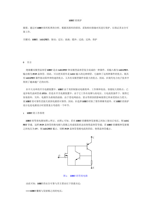
1 IGBT的工作原理IGBT的等效电路如图1所示。
由图1可知,若在IGBT的栅极和发射极之间加上驱动正电压,则MOS FET导通,这样PNP晶体管的集电极与基极之间成低阻状态而使得晶体管导通;若IGBT的栅极和发射极之间电压为0V,则MOSFET截止,切断PNP晶体管基极电流的供给,使得晶体管截止。
图1 IGBT的等效电路由此可知,IGBT的安全可靠与否主要由以下因素决定:——IGBT栅极与发射极之间的电压;——IGBT集电极与发射极之间的电压;——流过IGBT集电极-发射极的电流;——IGBT的结温。
如果IGBT栅极与发射极之间的电压,即驱动电压过低,则IGBT不能稳定正常地工作,如果过高超过栅极-发射极之间的耐压则IGBT可能永久性损坏;同样,如果加在IGBT集电极与发射极允许的电压超过集电极-发射极之间的耐压,流过IGBT集电极-发射极的电流超过集电极-发射极允许的最大电流,I GBT的结温超过其结温的允许值,IGBT都可能会永久性损坏。
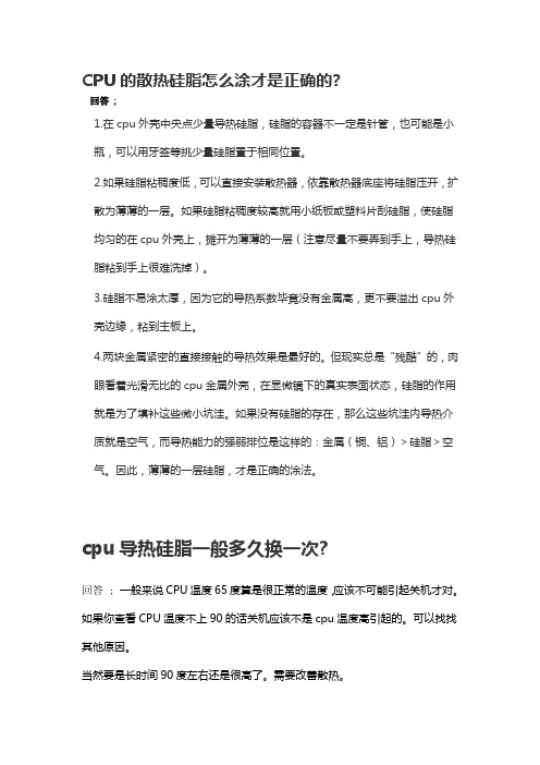
CPU的散热硅脂怎么涂才是正确的?回答;1.在cpu外壳中央点少量导热硅脂,硅脂的容器不一定是针管,也可能是小瓶,可以用牙签等挑少量硅脂置于相同位置。
2.如果硅脂粘稠度低,可以直接安装散热器,依靠散热器底座将硅脂压开,扩散为薄薄的一层。
如果硅脂粘稠度较高就用小纸板或塑料片刮硅脂,使硅脂均匀的在cpu外壳上,摊开为薄薄的一层(注意尽量不要弄到手上,导热硅脂粘到手上很难洗掉)。
3.硅脂不易涂太厚,因为它的导热系数毕竟没有金属高,更不要溢出cpu外壳边缘,粘到主板上。
4.两块金属紧密的直接接触的导热效果是最好的。
但现实总是“残酷”的,肉眼看着光滑无比的cpu金属外壳,在显微镜下的真实表面状态,硅脂的作用就是为了填补这些微小坑洼。
如果没有硅脂的存在,那么这些坑洼内导热介质就是空气,而导热能力的强弱排位是这样的:金属(铜、铝)>硅脂>空气。
因此,薄薄的一层硅脂,才是正确的涂法。
cpu导热硅脂一般多久换一次?回答 ; 一般来说CPU温度65度算是很正常的温度,应该不可能引起关机才对。
如果你查看CPU温度不上90的话关机应该不是cpu温度高引起的。
可以找找其他原因。
当然要是长时间90度左右还是很高了。
需要改善散热。
如果你已经把风扇拔下来清理过后,那确实要重新涂抹硅脂。
如果只是把风扇上的灰清理了就不用动了。
硅脂抹上,安装好风扇后,没什么问题的话一般是不需要更换的。
CPU导热硅脂导电吗?回答 ; 那种最普通白色的硅脂是不导电的,但硅脂有很多产品,不同的硅脂其电气特性,导热能力也是不相同的。
为了提高导热率,就有了渗银硅脂,渗铜硅脂,这样掺入金属颗粒的硅脂,其就有了导电性,像笔记本CPU,涂抹硅脂就需要注意不能流出cpu芯片顶盖,到CPU四周的电容上,导热硅脂是不是绝缘的?回答 ; 导热硅脂是绝缘的。
导热硅脂俗称散热膏,导热硅脂以有机硅酮为主要原料,添加耐热、导热性能优异的材料,制成的导热型有机硅脂状复合物,用于功率放大器、晶体管、电子管、CPU等电子原器件的导热及散热,从而保证电子仪器、仪表等的电气性能的稳定。
图1
4.4.2 本司需要印刷导热硅脂的物品有陶瓷基片及功率管,根据本体大小选择对应的底座及钢网并安装在工装上后,并对工装进行清洁,工装上不能有杂物,然后如下图2将须印刷硅脂的物品放置到底座的开槽中(功率管金属面要朝上),物品本体应完全在开槽中:
图2
4.4.3 如上图陶瓷基片或功率管放置好后,将钢网盖下,查看钢网开孔与陶瓷基片或功率管的对位状况(然后取一些硅脂放于钢网的边缘处<人体正对的最前面>),然后双手握住刮刀(刮刀与钢网表面呈45°夹角),如下图3将钢网边缘处的导热硅脂刮刀钢网的开槽中,要求开槽中基本充满硅脂,这需要刮硅脂不要太快,若开槽中有区域遗漏印刷硅脂或印刷不均匀,应重新使用刮刀刮硅脂:
图3
4.4.4 硅脂印刷过程中须戴手先戴手套然后再戴指套,钢网刮过硅脂前后的对照如下图4、5;印刷硅脂OK 的陶瓷基片及功率管放置到防静电泡棉上,已印刷硅脂面朝上,如下图6;轻抬钢网取印刷好的物品时,若个别陶瓷基片不自动脱离下来,用手轻拍钢网或用竹签等尖锐而接触面小的东西轻触陶瓷基片使之脱离即可,如下图7;
图4 图5
图6 图7
4.4.5导热硅脂厚度一般要求80~140µm之间,员工每天需对每一工装进行一次硅脂涂层厚度的测量(如果该工装的使用频率小于每天一次,则以实际的使用情况进行统计);硅脂涂层测量工具为不锈钢梳规,将梳规垂直刮过硅脂涂层,以梳规上规齿是否粘有硅脂来判定硅脂涂层的厚度。
比如刻度为90µm的规齿上粘有硅脂,而100µm的规齿上未粘有硅脂,则说明硅脂的厚度在90~100µm之间,记录的硅脂涂层厚度为。

导热硅脂和导电膏要正确使用决不能依赖导热硅脂和导电膏要正确使用决不能依赖2011年09月27日大功率电力电子器件,包括整流管、晶闸管、IGBT等在使用时必须安装在散热器上,以便把工作时器件自身功耗发热产生的热量用自冷、风冷或水冷的方式散发掉。
这是当前流行的做法。
此两部件各有一个传热平面互相紧贴,用紧固的办法安装在一起。
模块型器件底板是一块十分平整的铜板,它与内部芯片之间有一层导热良好的陶瓷类绝缘薄片,故此底板的功能仅为散热。
平板或螺栓型外壳的器件,它们的芯片与外壳不绝缘。
外壳是该器件的一个电极。
器件安装在散热器上后,两者接触平面不但是散热的通道,还是器件电流流经之处。
由此可见,器件与散热器接触的平面在表面不平度和粗糙度上要求是非常高的,以求尽可能减少两者之间的缝隙。
接触不良将会造成接触电阻和接触热阻大的问题。
于是出现了导热硅脂和导电膏类的糊状材料,声称此类材料具有较高的导热或导电性能。
用来填充两平面之间的空隙,会减少它们间的接触电阻和接触热阻。
于是就有人误解成这两种材料导热或导电性能能与铜媲美。
使用时用刷子刷、滚子压,涂上了不薄的一层,紧固后边缘还会挤出不少来。
实质上,这样做大错而特错,其结果适得其反。
现在让我们来分析这两种材料。
我们暂且不谈它们的化学性质和使用寿命,仅就它们的功能进行分析:1,导热硅脂:从导热系数来看,纯铜为:383 瓦/米℃;纯铝为:204瓦/米℃。
而导热硅脂仅为:1瓦/米℃到 6瓦/米℃。
与纯铜相比,导热硅脂导热性能仅为纯铜的1/64到1/383。
相差达六十多倍到三百八十多倍。
这里只能说导热硅脂的导热性能比空气强(空气的导热系数为 0.026 瓦/米℃,导热硅脂的导热系数为空气的38到231倍)。
仅此而言,把它当器件与散热器之间缝隙的填充物也只是权宜之计。
正确的做法是只涂极簿的一层。
器件与散热器接触平面的金属间得让它们互相接触、紧紧相贴,导热硅脂只起填充空隙之用,免得空隙中存在空气,导热更差。

浅谈 IGBT失效分析摘要:绝缘栅双极晶体管(IGBT)是由功率MOSFET和双极晶体管(BJT)复合而成的一种新型的电力半导体器件,它集两者的优点于一体,具有输入阻抗大、驱动功率小、控制电路简单、开关损耗小、速度快及工作频率高等特点,成为目前最有应用前景的电力半导体器件之一。
在轨道交通、航空航天、新能源、智能电网、智能家电这些朝阳产业中,IGBT作为自动控制和功率变换的关键核心部件,是必不可少的功率“核芯”。
采用IGBT进行功率变换,能够提高用电效率,提升用电质量,实现节能效果,在绿色经济中发挥着无可替代的作用。
关键词:IGBT;电力半导体;频率;功率本文研究大功率交流传动电力机车技术平台及大功率交流传动内燃机车技术平台,参考了国内外文献,通过对试验和应用数据的搜集、统计、整理,发现了一些典型的IGBT模块失效案例,并对其进行了失效特征分析,具体如下:1 过压失效1.1集-射极过压失效失效位置发生在有源区的边缘处,如图1(a)所示。
可见,芯片表面靠近内侧保护环处有小面积轻微烧损。
发生失效的条件:一是芯片击穿电压不满足要求,或者芯片的击穿电压发生退化;二是IGBT工作时发生异常,导致芯片承受的电压超过其可以承受的额定击穿电压。
1.2栅-射极过压失效失效位置发生在栅极与发射极隔离区,如图1(b)所示。
失效特征表现为芯片表面栅极与发射极隔离区上有熔点。
发生失效的条件:一是芯片栅极氧化层质量差,耐压不满足要求,或者芯片的栅极氧化层耐压发生退化;二是工况导致栅极过电压或电路产生栅极震荡。
2 过流失效2.1短路失效失效位置发生在IGBT有源区(不含栅极),如图2所示。
失效表现为模块中多个IGBT 芯片同时严重烧毁。
发生失效的条件:一是芯片短路安全工作区不能满足系统设计要求,或者短路安全工作区发生退化;二是工况发生异常,IGBT回路出现短路且IGBT未能及时被保护;三是半桥臂出现短路(IGBT或续流二极管),导致另一半桥臂IGBT被短路,发生短路失效;四是工作环境温度升高,导致芯片结温升高,短路安全工作区范围变小;五是控制信号问题,导致IGBT误开关,引起(桥臂)短路失效。
导热硅脂的涂抹方法导热硅脂是一种具有优良导热性能的绝缘材料,广泛应用于电子元件、散热器、发热器等领域。
在涂抹导热硅脂时,正确的涂抹方法是确保导热性能的关键。
下面,我将详细介绍导热硅脂的涂抹方法。
首先,准备工作非常重要。
涂抹导热硅脂之前,需要将发热元件和散热器等清洁干净。
使用无灰纸或棉布等柔软的材料擦拭,确保表面没有灰尘、油污等杂质。
同时,也需要注意自身的清洁卫生,避免在指间留下油脂和污渍。
在准备好之后,可以开始涂抹导热硅脂了。
一般来说,涂抹导热硅脂的方法有刮涂法、压力法和滴涂法等。
下面将逐一介绍这些方法。
刮涂法:这是一种常用的涂抹方法。
首先,将导热硅脂挤出一定长度的硅胶,并切成小块。
然后,使用刮板或刮刀,将硅胶块横向刮平,使其成为平坦的片状。
接着,将硅胶片均匀地涂抹在需要导热的元件上。
在涂抹的过程中,可以适当调整厚度和平整度,确保导热硅脂能够紧密地贴合表面。
压力法:这是一种适用于小面积涂抹的方法。
首先,将导热硅脂挤出一定长度的硅胶,并切成小块。
然后,使用一根修整好的塑料棒或橡皮棒等工具,将硅胶块直接压到元件表面上。
在压力的作用下,硅胶块会变形,并与表面紧密贴合,形成均匀的导热膜。
滴涂法:这是一种适用于小电子元件的涂抹方法。
首先,将导热硅脂挤出一定长度的硅胶。
然后,使用一根修整好的细管或细长刷子等工具,将硅胶滴在需要导热的元件上。
在滴涂的过程中,要控制好滴涂的数量和位置,确保硅胶能够均匀地布满整个表面。
无论使用哪种涂抹方法,都需要注意以下几点:1. 厚度控制:导热硅脂的导热性能与其厚度有关。
一般来说,导热硅脂的厚度应根据具体的使用要求进行控制。
通常情况下,厚度在0.5mm到1.5mm之间是比较合适的。
2. 均匀涂抹:无论使用哪种涂抹方法,都需要确保导热硅脂能够均匀地涂抹在整个表面上。
均匀涂抹可以提高导热性能,避免因涂抹不均匀而导致的局部温度过高的问题。
3. 避免气泡:在涂抹过程中,要注意排除气泡。
IGBT模块认证测试规范拟制:张广文日期:2011-03-07审核:姜明日期:__________批准:董瑞勇日期:__________更改信息登记表规范名称:IGBT模块认证测试规范规范编码:评审会签区:目录1.目的42.范围43.定义44.引用标准55.测试设备66.测试环境67.测试项目77.1规格参数比对77.2封装结构测试87.2.1封装外观检查87.2.2封装外形尺寸测试97.2.3基板平整度测试97.2.4封装内部结构测试117.3晶体管电特性测试127.3.1集-射极耐压VCES测试127.3.2 IGBT集-射极饱和压降VCE(sat)测试137.3.3 IGBT栅-射极阀值电压VGE(th)测试147.3.4 IGBT内置二极管正向压降VF测试157.4 Ices和IR测试167.5绝缘耐压测试187.6高温电应力老化测试207.7高低温老化测试217.8 NTC热敏电阻特性测试227.9驱动波形测试227.9.1驱动波形质量测试237.9.2开通关断时间测试257.9.3驱动电压幅值测试267.9.4死区时间测试277.10限流测试287.11均流测试297.12短路测试307.13温升测试347.14 IGBT晶元结温测试368.数据记录及报告格式40IGBT模块认证测试规范1.目的检验IGBT模块各项性能指标是否满足标准和产品设计要求。
本规范主要从IGBT结构、电气性能、可靠性等方面全面评估IGBT模块各项性能指标。
2.范围本规范规定的IGBT模块性能测试方法,适用于英威腾电气股份有限公司IGBT模块器件选型认可及产品开发过程中IGBT模块单体性能测试。
3.定义绝缘栅双极型晶体管IGBT(Insulated Gate Bipolar Transistor):是由BJT(双极型三极管)和MOS(绝缘栅型场效应管)组成的复合全控型电压驱动式功率半导体器件,兼有MOSFET的高输入阻抗和GTR的低导通压降两方面的优点。
IGBT组装工艺流程IGBT是大功率变频器核心元器件,其性能好坏直接决定整个产品的质量,因此,其组装过程要求标准、专业、规范的生产工艺。
我司工业设计部单艳梅根据实际生产经验和工艺流程总结出了一套完备的IGBT组装工艺,今天刊登出来,与大家一起分享、学习。
目前IGBT等高精密器件的组装生产是采用一人操作多项工作的方式,这容易造成装配动作不规范、装配的产品达不到专业水平,从而影响产品装配质量的问题。
实操过程中对散热器以及IGBT对表面平整度都有很严格的要求,因此当装配作业时就需要专业的工作平台,同时采用合适的运输工具及采取相应的保护措施来避免元器件表面受损。
另外,如果操作过程中工人徒手搬运散热器或IGBT,一旦发生意外失手情况,造成元器件损坏,就会产生不小的经济损失。
为了克服上述缺陷,提高了装配产品的质量和效率,特设计了本IGBT 的组装工艺流程,其具体如下。
1、工艺流程步骤本次采用的工艺流程方案是在IGBT的组装过程中,设置若干个工位点,并在每个对应的工位点划定工位器具区域,配备组装使用工具,同时设立若干检验员,对整个工艺过程进行检验。
具体工艺步骤如下:(1)设置工位1,抹绝缘硅脂;①将IGBT反扣在专用固定工装支架上;②涂抹绝缘硅脂前用干净的棉布或者用干净的棉布蘸取酒精擦拭清理IGBT;③涂抹导热硅脂时,用专用的钢质刮刀把绝缘硅脂均匀涂抹在每个丝网的网孔内;④把涂抹好绝缘硅脂的IGBT轻置放在散热器上指定的安装位置,放置时应对孔一次性放置到位;(2)设置工位2,预紧IGBT和散热器;在对IGBT固定安装时,用扭力扳手分别对不同规格的IGBT用O.4NM-0.6NM的均力按端子顺序预紧螺栓。
一般情况下IGBT有以下三种不同端子顺序,其中:六个端口的顺序为:2-5-3-6-1-4,八个端口的顺序为:2-6-3-7-4-8-1-5,十四个端口的顺序为:4-11-3-10-5-12-2-9-6-13-1-8-7-14;(3)设置工位3,紧固散热器;按照上述步骤(2)中②同样顺序用扭力扳手采用4NM-6NM的均力进行紧固螺栓;图1预紧螺栓顺序2 3 4 5 6 714 13 12I11D9 8图3预紧螺栓顺序(4)设置工位4,按照位置装配加热电阻;(5)设置工位5,固定驱动电路板;按照图示位置把驱动电路板固定在IGBT相应位置;(6)设置工位6,进行模块内部接线;以上步骤按照顺序操作,完成之后送入半成品放置区域,形成一条由流水线始端走向末端并转入半成品放置区域的IGBT的组装工艺图4IGBT装配组件结构示意图2、工艺流程特点采用此工艺流程后,具有以下特点:1、采用这种流程作业方式可以让工人各司其职,每个人只专长自己所在工位的装配内容,有利于标准作业化的执行,加强工人装配的熟练程度,提高产品质量。
Thermal grease for Infineon modulesWhat should be the behavior and how a grease has to look likeBaginskiIFAG AIM PMD ID AEInfineon modules with baseplate: Roughness of baseplateR Zmax. = 16 µm;R Ztyp. = 4 – 6 µmInfineon modules without baseplate: Roughness of ceramicR Zmax. = 9 µm; R Ztyp. = 3 – 4 µmHeatsink: Specification of roughness regarding Application Note Modules with and without baseplate: R Zmax. = 10 µmThe information given in this presentation is given as a hint for the implementation of the Infineon Technologies components only and shall not be regarded as any description of warranty of a certain functionality, conditions or quality of the Infineon Technologies components. The statements contained in this communication, including any recommendation or suggestion or methodology, are to beExample of roughness of baseplate and heatsinkThe information given in this presentation is given as a hint for the implementation of the Infineon Technologies components only and shall not be regarded as any description of warranty of a certainfunctionality, conditions or quality of the Infineon Technologies components. The statements contained in this communication, including any recommendation or suggestion or methodology, are to beThermal conductivity:Copper: λ ≈ 390 W / mKAluminium: λ ≈ 237 W / mKThermal compound: λ ≈ 1 W / mKCopper=> Thermal barrierTIMAluminiumThe information given in this presentation is given as a hint for the implementation of the Infineon Technologies components only and shall not be regarded as any description of warranty of a certain functionality, conditions or quality of the Infineon Technologies components. The statements contained in this communication, including any recommendation or suggestion or methodology, are to beR th CH metall << R th CH thermal grease 0.004 mK/W << 1 mK/W << R th CH air << 42 mK/W=> Metal to Metal contact essential=> Thermal grease that fills only the gapes is preferedThe information given in this presentation is given as a hint for the implementation of the Infineon Technologies components only and shall not be regarded as any description of warranty of a certain functionality, conditions or quality of the Infineon Technologies components. The statements contained in this communication, including any recommendation or suggestion or methodology, are to beThermal grease consists of different componentsOily partsOnly needed to adjust the viscosity of the greaseThermal conducting partsNecessary to conduct baseplate and heatsink togetherThe information given in this presentation is given as a hint for the implementation of the Infineon Technologies components only and shall not be regarded as any description of warranty of a certainfunctionality, conditions or quality of the Infineon Technologies components. The statements contained in this communication, including any recommendation or suggestion or methodology, are to beThermal interface material: Example for better understandingGrain size: Up to 70 µmThe information given in this presentation is given as a hint for the implementation of the Infineon Technologies components only and shall not be regarded as any description of warranty of a certainfunctionality, conditions or quality of the Infineon Technologies components. The statements contained in this communication, including any recommendation or suggestion or methodology, are to beExample: Thermal grease with 40 µm size in application Temperaturedrop390 W/mKSmall temp. dropBaseplateNo chance to move Oilypart1 W/mKBig temp. drop Heat conductingpart237 W/mKSmalltemp. dropHeatsinkThe information given in this presentation is given as a hint for the implementation of the Infineon Technologies components only and shall not be regarded as any description of warranty of a certain functionality, conditions or quality of the Infineon Technologies components. The statements contained in this communication, including any recommendation or suggestion or methodology, are to beExample of grains of 40 µm sizeGrease workslike distanceBaseplatespacersHeatsink=> R thCH = badThe information given in this presentation is given as a hint for the implementation of the Infineon Technologies components only and shall not be regarded as any description of warranty of a certain functionality, conditions or quality of the Infineon Technologies components. The statements contained in this communication, including any recommendation or suggestion or methodology, are to beExample: Thermal grease with 5 µm size in applicationTemperaturedropBaseplateHeatsinkThe information given in this presentation is given as a hint for the implementation of the Infineon Technologies components only and shall not be regarded as any description of warranty of a certain functionality, conditions or quality of the Infineon Technologies components. The statements contained in this communication, including any recommendation or suggestion or methodology, are to beExample of grains of 5 µm sizeHole to fix module with the heatsinkBaseplateHeatsinkMetal to metal contact possible => R thCH = goodThe information given in this presentation is given as a hint for the implementation of the Infineon Technologies components only and shall not be regarded as any description of warranty of a certain functionality, conditions or quality of the Infineon Technologies components. The statements contained in this communication, including any recommendation or suggestion or methodology, are to beViscosity of thermal grease: High viscosity (hard)Baseplate Dots ofgreaseViscosity of thermal grease: Low viscosity (fluid)Baseplate Heatsink Baseplate Heatsink Dots of greaseGreasecomesoutBaseplateThe information given in this presentation is given as a hint for the implementation of the Infineon Technologies components only and shall not be regarded as any description of warranty of a certain functionality, conditions or quality of the Infineon Technologies components. The statements contained in this communication, including any recommendation or suggestion or methodology, are to beHeatsinkRoughness of heatsinkR Ztyp. = 6 µmR Zmax. = 1 µm HeatsinkPermanent distanceThe information given in this presentation is given as a hint for the implementation of the Infineon Technologies components only and shall not be regarded as any description of warranty of a certain functionality, conditions or quality of the Infineon Technologies components. The statements contained in this communication, including any recommendation or suggestion or methodology, are to beRoughness of heatsinkBaseplateR Ztyp. = 6 µmR Zmax. = 10 µmHeatsinkCrossover possible The information given in this presentation is given as a hint for the implementation of the Infineon Technologies components only and shall not be regarded as any description of warranty of a certain functionality, conditions or quality of the Infineon Technologies components. The statements contained in this communication, including any recommendation or suggestion or methodology, are to beConsiderations of thermal foilFoil workslike distanceBaseplatekeeperHeatsinkPermanent air-> bad RthThe information given in this presentation is given as a hint for the implementation of the Infineon Technologies components only and shall not be regarded as any description of warranty of a certain functionality, conditions or quality of the Infineon Technologies components. The statements contained in this communication, including any recommendation or suggestion or methodology, are to beBefore first heat up (no phase change)F=3NmF=3NmFoil works like distance keeperThe information given in this presentation is given as a hint for the implementation of the Infineon Technologies components only and shall not be regarded as any description of warranty of a certain functionality, conditions or quality of the Infineon Technologies components. The statements contained in this communication, including any recommendation or suggestion or methodology, are to beAfter heating up (phase change)Foil works like distance spacers F=?Nm Loose of pressureBaseplateHeatsinkF=?NmThe information given in this presentation is given as a hint for the implementation of the Infineon Technologies components only and shall not be regarded as any description of warranty of a certain functionality, conditions or quality of the Infineon Technologies components. The statements contained in this communication, including any recommendation or suggestion or methodology, are to beConclusion of considerationsThe grease has to fill only the roughness of the baseplate and the roughness of the heatsinkThis do not prevent metal to metal contact where possible The grease has to be fluid enough to spread and to flow outThis guarantees small thickness of grease between baseplate and heatsinkThis guarantees a good thermal contactThe roughness of the heatsink should be under considerations The information given in this presentation is given as a hint for the implementation of the Infineon Technologies components only and shall not be regarded as any description of warranty of a certain functionality, conditions or quality of the Infineon Technologies components. The statements contained in this communication, including any recommendation or suggestion or methodology, are to beThe information given in this presentation is given as a hint for the implementation of the Infineon Technologies components only and shall not be regarded as any description of warranty of a certain functionality, conditions or quality of the Infineon Technologies components. The statements contained in this communication, including any recommendation or suggestion or methodology, are to be。