德国peiseler派士乐数控转台样本
- 格式:pdf
- 大小:4.88 MB
- 文档页数:16
Levante Sistemas deAutomatización y Control S.L.CatálogosLSA Control S.L. - Bosch Rexroth Sales Partner Ronda Narciso Monturiol y Estarriol, 7-9Edificio TecnoParQ Planta 1ª Derecha, Oficina 14(Parque Tecnológico de Paterna)46980 Paterna (Valencia)Telf. (+34) 960 62 43 01*************************www.boschrexroth.esADF Main Spindle MotorsDOK-MOTOR*-ADF********-PRJ1-EN-P Project Planning Manualmannesmann Rexroth engineeringIndramat 271431About this documentationTable of ContentsT able of Contents1. Introducing Main Spindle Motors1. Introducing Main Spindle Motors1. Introducing Main Spindle Motors2. T echnical Explanations2. T echnical Explanations2. Technical Explanations2. T echnical ExplanationsWhen mounting the motor in orientation IM V3, liquids must be pre-vented from collecting at the output shaft over longer periods oftime. Even if a shaft sealing ring is used, it will not prevent liquidsfrom penetrating into the motor housing along the output shaft. Output shaft Plain Output ShaftFor friction-locked shaft-hub connections.The higher run quality and the backlash-free connection between shaft andhub are a significant advantage of this preferred and recommended design.Output Shaft with KeyFor a form-fitting shaft-hub connection.This connection is suited to take up torques of a constant direction. The hubmust be axially secured in this case. A threaded center hole is on the over-hang.Balanced with full key:The rotor is balanced with the key used in the shaft-hub assembly. The rotoris balanced with the full key. A balanced, interconnecting part (toothedwheel, etc.) must be used. The keyway in the hub is not dependent upon thelength of the key.Balancing with half a key:There is half a key in the keyway in the shaft. The mass ratios occurring atthe keyway are comparable to those of a plain shaft. If a full key is inserted,then the projecting section of the key creates a state of imbalance. The rotorwith the rull key is not balanced.The interconnecting part must equalize this state of imbalance of the rotor.The keyway in the hub must correspond to the length of the key. Use a step-ped key for shorter keyways.2. T echnical Explanations2. T echnical ExplanationsIf the motor has been stored for an extended period of time, then please note the following prior to commissioning it.Do not conduct the cable to the high-resolution motor feedback over a terminal strip as it is highly susceptible to interference!Do not conduct the cable to the high-resolution motor feedback over a terminal strip as it is highly susceptible to interference!7. Condition at DeliveryWarningThere is an envelope with delivery slip attached to the carton. There is alsoa barcode sticker on the packaging. Caution! There is considerable tension in the taut band!There is the danger of injury from the uncontrolled movements of the taut bands when these are cut through!Maintain a sufficient safety distance! Remove taut bands carefully!AchtungHochwertige ElektronikAttentionFragile ElectronicsVor Nässe schützen Nicht werfennicht belasten Nicht kantenDo not apply load Do not tipDo not drop Keep dryPick the motor up only at the mounted eye bolts. If it is not picked up at these points, then the coolant inlet and outlet pipes can be damaged or destroyed!crane and chains.Figure 9.2 depicts how the heavy motors should be lifted with the help of a10. Mounting and Installation Guidelines。

机电工程学院毕业设计说明书设计题目: CNC320立式数控转台设计学生姓名:赵辉辉学号: 201215010621专业班级:机制Y1208指导教师:王宗才2016年 5 月28 日目录第1章引言 ----------------------------------------------------------------------------------- 11.1 设计要求----------------------------------------------------------------------------- 11.2设计思路----------------------------------------------------------------------------- 1 1.3设计准则 ------------------------------------------------------------------------------------------ 1第2章总体方案论证------------------------------------------ 32.1数控转台的布局 --------------------------------------------------------------------------------- 32.2驱动元件的选择 --------------------------------------------------------------------------------- 32.2.1 步进电动机 ---------------------------------------------------------------------------- 32.2.2伺服电动机 ---------------------------------------------------------------------------- 3 2.3传动方案的确定 --------------------------------------------------------------------------------- 4 2.4工作台的制动 ------------------------------------------------------------------------------------ 5 2.5工作台的定位 ------------------------------------------------------------------------------------ 7第3章数控转台的零件设计------------------------------------ 83.1伺服电动机的确定 ----------------------------------------------------------------------------- 83.2齿轮传动机构的设计-------------------------------------------------------------------------- 83.2.1齿轮的设计 --------------------------------------------------------------------------- 83.2.2齿轮机构的消隙 ----------------------------------------------------------------- 10 3.3蜗轮及蜗杆传动机构的设计 ------------------------------------------------------------- 103.3.1蜗轮及蜗杆的设计---------------------------------------------------------------- 103.3.2蜗轮蜗杆副机构的消隙 -------------------------------------------------------- 12 3.4蜗杆轴的计算与校核 ----------------------------------------------------------------------- 13 3.4.1轴的结构设计----------------------------------------------------------------------- 13 3.4.2轴的计算与校核-------------------------------------------------------------------- 13 3.5轴承的选用 ------------------------------------------------------------------------------------ 16 3.5.1轴承的类型 -------------------------------------------------------------------------- 163.5.2轴承的配合 -------------------------------------------------------------------------- 16 3.5.3 轴承的润滑 -------------------------------------------------------------------------- 163.5.4轴承的密封 -------------------------------------------------------------------------- 163.5.5 轴承的预紧 -------------------------------------------------------------------------- 16 3.6夹紧力的计算------------------------------------------------------------------------------- 16 第4章数控转台的控制系统设计------------------------------ 18 第5章数控转台的三维造型---------------------------------- 195.1蜗轮的三维造型---------------------------------------------------------------------------- 19 5.2 蜗杆的三维造型 ---------------------------------------------------------------------------- 215.3工作台的三维造型 ------------------------------------------------------------------------ 235.4 底座的三维造型 --------------------------------------------------------------------------- 245.5 底座与工作台的装配 --------------------------------------------------------------------- 245.6 夹紧瓦的三维造型------------------------------------------------------------------------ 24 结论-------------------------------------------------------- 27 设计总结 --------------------------------------------------------------------------------------- 28致谢---------------------------------------------------------------------------------------------- 29参考文献 -------------------------------------------------------------------------------------------------- 30摘要为了使一些特殊的零件能够在普通机床上加工出来,减少零件的加工费用,扩大机床的加工性能是非常有必要的。
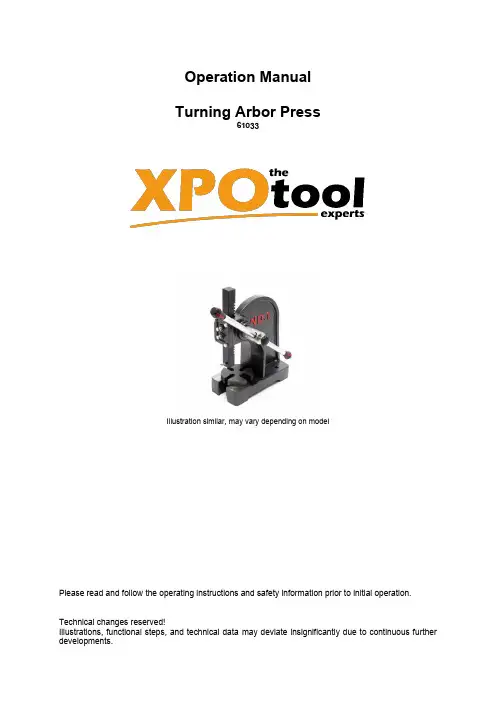
Operation ManualTurning Arbor Press61033Illustration similar, may vary depending on modelPlease read and follow the operating instructions and safety information prior to initial operation. Technical changes reserved!Illustrations, functional steps, and technical data may deviate insignificantly due to continuous further developments.The information contained in this document may alter at any time without prior notice. No part of this document may be copied or otherwise duplicated without prior written consent. All rights reserved. WilTec Wildanger Technik GmbH cannot be held liable for any possible mistakes in this operating man-ual, nor in the diagrams and illustrations shown.Although WilTec Wildanger Technik GmbH has made every possible effort to ensure that this operating manual is complete, accurate, and up-to-date, errors cannot be ruled out entirely.If you have found an error or wish to suggest an improvement, we look forward to hearing from you. Send us an e-mail to:*******************or use our contact form:https://www.wiltec.de/contacts/The most recent version of this manual in several languages can be found in our online shop:https://www.wiltec.de/docsearchOur postal address is:WilTec Wildanger Technik GmbHKönigsbenden 1252249 Eschweiler GermanyTo return your goods for exchange, repair, or other purposes, please use the following address. Atten-tion! To allow for a trouble-free complaint or return, it is important to contact our customer service team before returning your goods.RetourenabteilungWilTec Wildanger Technik GmbHKönigsbenden 2852249 Eschweiler GermanyE-mail: *******************Phone: +49 2403 55592–0Fax: (+49 2403 55592–15)IntroductionThank you for choosing to purchase this quality product. To minimise the risk of injury, we ask you to always take some basic safety precautions when using this product. Please read this operating manual carefully and make sure that you understand it.Keep these operation instructions in a safe place.Safety instructions•Before use, check the device for completeness and functionality.•Never us a damaged or dysfunctional device. Have a qualified technician check the device.•Always work with care and the attention required.•Keep your working area tidy and well illuminated. A cluttered and poorly lit workplace increases the risk of accidents.•Keep children away from the device.•Thoroughly store the device if not using it. Store it in a dry place.•Do not modify the device in any way.•Only use original spare parts.•Do not force the device; otherwise, it could be damaged.•Only use the device according to the intended use defined in this manual. Pay special attention to the maximum dimensions.•Wear appropriate protection equipment (safety gloves, working shoes, protective goggles, etc.).•While working, ensure a safe stand.•Handle the device with care.•Before use, control all screws and nuts for safe seat.•Regularly inspect the device to find damaged spots or dysfunctional components.•After maintaining the device, remove all tools.•If parts are damaged, replace them with original spare parts.•Do not use the device when being tired or under the influence of alcohol, drugs, or medicine. Technical specificationsExploded view and parts listImportant Note: Reproduction and any commercial use (of parts) of this operating manual, requires a written permission of WilTec Wildanger Technik GmbH.。
格瑞维尔国际经贸(北京)有限公司 企业简介格瑞维尔国际经贸(北京)有限公司是一家总部位于北京的专业经营机械,数控机床功能附(部)件及生产数控机床的国际经贸企业,与欧美、亚澳等全球知名企业建立了长期合作伙伴关系。
公司致力于引进世界高端机床和重要功能附(部)件,服务于中国制造业,同时将中国性价比高的机床产品销往全球用户。
格瑞维尔是意大利欧姆雷特(Omlat)电主轴中国总代理;也是成立于1819年被欧洲著名数控机床制造商誉为“转台王”的世界高端数控转台制造商——德国派士乐(peiseler)的中国总代理。
我们建立了强大的供应商网络,拥有稳定的客户群体,在机械制造、汽车、航空航天、铁路、新能源、船舶、环保等领域深受用户喜爱。
配有现代化的网络营销平台及专业的CRM,ERP管理平台,拥有高效的管理团队及经验丰富的技术团队,具有雄厚的技术研发实力。
目前公司有员工50多人,具有中级以上职称或本科以上学历员工达85%以上,均为国内外著名高等院校优秀毕业生、硕士和博士生;也有在国内外工厂从事产品设计、产品工艺、机械制造、设备维修等多年丰富工作经验的高级工程师和资深专家。
电主轴部,派士乐部、技术部、进口部、出口部、船务部、售后服务部、展览部、备件仓库、生产制造部、国内外各办事处,各部门互相配合,高效运营,以综合实力强,专业服务好闻名世界。
选择格瑞维尔就是选择了高品质,拥有了世界尖端技术。
我们致力于将世界尖端技术引入中国数控机床制造、汽车、航空航天等,大力推动中国数控机床走向世界技术最前沿。
我们的团队工作严谨,技术精湛,认真负责,精心为客户提供各种先进技术解决方案;做到24小时内及时应答用户各种问题。
卓越技术铸就完美品质,用心服务成就信誉第一,客户的满意,是我们的不懈追求。
意大利高速精密电主轴·静压主轴意大利Omlat公司是欧洲专业的高速主轴、电主轴生产商,具有70多年的主轴研发生产经验,具有精湛的设计加工工艺和领先的技术并不断进行技术研发创新,在全球客户中享有良好的声誉。
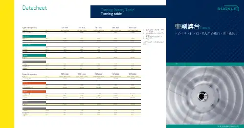
德国Peiseler 转台(涡轮蜗杆传动结构)与其它品牌转台特性对比表
序号
功能及特性
德国Peiseler 数控转台
其它品牌转台
1 主轴承
所有派士乐转台使用 轴承第一品牌--德国INA 公司的转台专用YRT 轴承
YRT 特点: 1.轴向是两排滚柱,径向是一排滚柱,可以同时承受轴向和径向的压力,承重大,扭矩大,精度高。
2.YRT 轴承都已配好,无需预紧(如图).
止推轴承或其他轴承:
1.和YRT 转台专用轴承相比,承重小,抗倾覆力矩能力低。
2. 止推轴承的精度靠预紧,容易产生间隙,丧失精度。
2
承重和抗扭矩性
YRT 轴承的结构决定了派士乐转台承重大,刚性好,抗扭矩性好. 工件可以放在台面的任意位置加工.
止推轴承的结构决定了转台承重及刚性一般,抗扭矩性能不好, 工件只能放在转台中心位置, 否则台面将严重跳动
向夹紧比径向夹紧的扭矩大
转动惯性
以承受更高的扭矩
很
度
好
轴向夹紧原理:
当红色管路充满压力油并加压时,粉色簧片变形并推动绿色刹车片向蓝色壳体移动,实现刹车。
泻压时,动作相反
4.OTT传
动Peiseler 是世界上最好的涡轮蜗杆制造商OTT公司的第一大客户,OTT涡轮蜗杆的特点:
1.采用双蜗杆技术,可调整间隙,没有反向间隙,从而保证了转台精度的稳定性:如图:
2.长时间使用磨损后只需重新调整蜗杆间隙,精度又恢复至出厂时精度。
而一般转台采用的是单蜗杆结构,不能起到调隙作用,
并且磨损后也不能再次调整。
德国SPINNER公司主要机床简述一.SB型超精密车床1.SB/C型:12刀位圆刀盘,控制系统SIEMENS 840D或者FANUC 18i,主轴转速:8000转/分棒料直径32mm,5000转/分棒料直径42mm,X=250mm, Z=285mm; 最大车削直径150mm, 床面上回转直径300mm2.S B/C-MC型:12刀位圆刀盘,控制系统SIEMENS 840D或者FANUC 18i,主轴转速:8000转/分棒料直径32mm,5000转/分棒料直径42mm,主轴带C轴功能,其中动力刀位6个X=250mm, Z=285mm; 最大车削直径150mm, 床面上回转直径300mm3.S B/C-T型:12刀位圆刀盘,控制系统SIEMENS 840D或者FANUC 18i,主轴转速:8000转/分棒料直径32mm,5000转/分棒料直径42mm,带尾架X=250mm, Z=285mm; 最大车削直径150mm, 床面上回转直径300mm4.S B/C-TMC型:12刀位圆刀盘,控制系统SIEMENS 840D或者FANU C 18i,主轴转速:8000转/分棒料直径32mm,5000转/分棒料直径42mm,主轴带C轴功能,带尾架,其中动力刀位6个X=250mm, Z=285mm; 最大车削直径150mm, 床面上回转直径300mm5.主要附件:a) 弹簧夹头座b) 弹簧夹头c) 动力卡盘d) 刀座套装e) 轴向动力头f) 径向动力头6.特点:X/Z轴均配有直线光栅尺,全闭环测量系统。
X/Z轴进给丝杠为行星滚柱式丝杠。
主轴内冷设计;电器柜装有空调器;可配线性刀架;以上均为标准配置7.精度:根据德国VDI/DGQ 3441标准X/Z轴分辨率0,0001毫米Tp:X轴=2微米,Z轴=3微米Ps:X/Z轴=0,4微米C轴分辨率0,0001 ,Tp=6秒;Ps=2,5秒工件精车后的圆度< 0,4微米二.PD型超精密车床1.PD/C-T型:16刀位圆刀盘,控制系统SIEMENS 840D或者FANUC 18i,主轴转速:8000转/分棒料直径32mm,5000转/分棒料直径42mm带CNC功能的尾架X=400mm, Z=400mm; 最大车削直径150mm, 床面上回转直径300mm2.PD/C-TMC型:16刀位圆刀盘,控制系统SIEMENS 840D或者FANUC 18i,主轴转速:8000转/分棒料直径32mm,5000转/分棒料直径42mm,主轴带C轴功能,带CNC功能的尾架,其中动力刀位8个X=400mm, Z=400mm; 最大车削直径150mm, 床面上回转直径300mm3.PD/C-S型:16刀位圆刀盘,带副轴;主/ 副轴具有极高的同步精度控制系统SIEMENS 840D或者FANUC 18i,主轴转速:8000转/分棒料直径32mm,5000转/分棒料直径42mm副轴转速:8000转/分棒料直径32mmX=400mm, Z=400mm, Q=400mm 最大车削直径150mm, 床面上回转直径300mm4.PD/C-SMC型:16刀位圆刀盘,带副轴;主/ 副轴具有极高的同步精度控制系统SIEMENS 840D或者FANUC 18i,主轴转速:8000转/分棒料直径32mm,5000转/分棒料直径42mm,副轴转速:8000转/分棒料直径32mm主/ 副轴带C轴功能,其中动力刀位8个X=400mm, Z=400mm,Q=400mm 最大车削直径150mm, 床面上回转直径300mm5.主要附件:a) 弹簧夹头座b) 弹簧夹头c) 动力卡盘d) 刀座套装e) 轴向动力头f) 径向动力头6.特点:X/Z/Q轴配直线光栅尺,全闭环测量系统。
潜力无限的棒料铣削中心SwissDeco 36 TB :首个棒料车削中心Sw issNano 7 : 单位面积生产更多工件关于移动出行的最新展望89 03-2019 中文403124122deco magazine 03-2019BOOST YOUR PRODUCTIVITYUtilis AG, Precision ToolsKreuzlingerstrasse 22, CH-8555 Müllheim, Switzerland***************,Phone 41 52 762 62 62, Fax 41 52 762 62 00++Room 512, Hua Nan MansionCN-200125 ShanghaiPhone 86 21 6109 6217, Fax 86 21 2301 0401++URMA Trading (Shanghai) Co.Ltd.Dept: Utilis China, Swiss Type Tools1988 Dongfang Road, Pudong New Districtmultidec ®-LUB 夹紧楔将冷却液精确地导向刀具切削刃。
灵活的挡块可实现安全快速的换刀。
高压至200 bar低压至30 barEMO – 德国汉诺威2019年9月16–21日大厅 5 / 展位 A703decomagazine 03-2019落狼|Swiss GT 13正是格里姆斯“追求完美,力求卓越”理念的解决方案。
46 德国市场对机床行业至关重要。
Tornos深知这一点并将继续证明其承诺。
”Tornos首席执行官 (Michael Hauser)4deco magazine 03-2019编者按|当前趋势的交互式展示Tornos首席执行官 (Michael Hauser)2019年汉诺威欧洲机床展将于9月16日至21日在德国汉诺威举行,对于我们的行业、金属加工界以及Tornos来说,这是一个重要活动,因为这是一个接触市场、倾听市场需求的机会。
The Technical Agreement技术协议1. NC Rotary Table, type: AWUP160 , with Counterbearing: GGP160数控回转工作台, 型号:AWUP160; 及,尾座,型号:GGP160转台加尾座统一命名为: WWUP1601. 1Technical Description 技术描述1.1 .1 Execution of table platen台面Table platen manufactured from Meehanite GGG cast-iron, which is hydraulic tightand also gives highest rigidity- Ground clamping surface, precisely machined工作台台面采用德国米汉纳GGG高等级铸铁,具有非常高的刚性。
夹紧面采用精密的机械加工完成。
1.1.2 Base 底座The base casting is manufactured from Meehanite GGG cast-iron, which ishydraulic tight and also gives highest rigidity and stiffness.- supporting surface precisely machined- equipped with clamping slots/fixing holes- body bottom prepared to be installed the client's machine工作台底座采用德国GGG高等级铸铁,具有非常高的刚性,采用独特的液压夹紧技术具有夹紧速度快,扭矩大,制动性强,平稳性高,抗倾覆力矩强的特点。
支撑面采用了精密机械加工完成。
配置有夹紧槽或安装孔。
工作台底座通过螺丝螺母安装在客户机床上1.1.3 Drive 驱动The table will be driven by servo motor of client'sWe are using worm and wheel sets from company Ott which have thehighest accuracy that is available in the market. It also has a patent pended zerobacklash adjusting system, where you can set backlash to zero with anydisassembly of the worm工作台驱动的伺服电机由客户自己提供。