土木 外文翻译
- 格式:doc
- 大小:185.00 KB
- 文档页数:16

学院:专业:土木工程姓名:学号:外文出处: Structural Systems to resist (用外文写)Lateral loads附件: 1.外文资料翻译译文;2.外文原文。
附件1:外文资料翻译译文抗侧向荷载的结构体系常用的结构体系若已测出荷载量达数千万磅重,那么在高层建筑设计中就没有多少可以进行极其复杂的构思余地了。
确实,较好的高层建筑普遍具有构思简单、表现明晰的特点。
这并不是说没有进行宏观构思的余地。
实际上,正是因为有了这种宏观的构思,新奇的高层建筑体系才得以发展,可能更重要的是:几年以前才出现的一些新概念在今天的技术中已经变得平常了。
如果忽略一些与建筑材料密切相关的概念不谈,高层建筑里最为常用的结构体系便可分为如下几类:1.抗弯矩框架。
2.支撑框架,包括偏心支撑框架。
3.剪力墙,包括钢板剪力墙。
4.筒中框架。
5.筒中筒结构。
6.核心交互结构。
7. 框格体系或束筒体系。
特别是由于最近趋向于更复杂的建筑形式,同时也需要增加刚度以抵抗几力和地震力,大多数高层建筑都具有由框架、支撑构架、剪力墙和相关体系相结合而构成的体系。
而且,就较高的建筑物而言,大多数都是由交互式构件组成三维陈列。
将这些构件结合起来的方法正是高层建筑设计方法的本质。
其结合方式需要在考虑环境、功能和费用后再发展,以便提供促使建筑发展达到新高度的有效结构。
这并不是说富于想象力的结构设计就能够创造出伟大建筑。
正相反,有许多例优美的建筑仅得到结构工程师适当的支持就被创造出来了,然而,如果没有天赋甚厚的建筑师的创造力的指导,那么,得以发展的就只能是好的结构,并非是伟大的建筑。
无论如何,要想创造出高层建筑真正非凡的设计,两者都需要最好的。
虽然在文献中通常可以见到有关这七种体系的全面性讨论,但是在这里还值得进一步讨论。
设计方法的本质贯穿于整个讨论。
设计方法的本质贯穿于整个讨论中。
抗弯矩框架抗弯矩框架也许是低,中高度的建筑中常用的体系,它具有线性水平构件和垂直构件在接头处基本刚接之特点。

淮阴工学院毕业设计外文资料翻译学院:建筑工程学院专业:土木工程(路桥方向)姓名:石洋学号:1081401526外文出处:工程力学杂志(用外文写)Journal of Engineering Mechanics 附件: 1.外文资料翻译译文;2.外文原文。
注:请将该封面与附件装订成册。
附件1:外文资料翻译译文Timoshenko 和剪切模型梁的动力学研究Noël Challamel1摘要:古典Timoshenko 梁模型和剪切梁模型常用于建筑行为模型都剪稳定性或动态分析。
该技术关注的是两种模型间的大量弯曲剪切刚度值的问题。
这是以两种模型分析研究了简支梁。
获得大量弯曲剪切刚度值的渐进解。
在一般情况下,实验在考虑大弯剪刚度值参数时证明该剪切梁模型不能从Timoshenko 模型中推断出来,这只是达到特定的几何参数在目前的例子。
作为结论,剪切模型的能力近似Timoshenko 模型,因为大量弯曲剪切刚度参数是坚定的依赖于横截面在边界状态下的材料和几何特性。
关键词:横波,结构力学,动态模型,脑电图仪,比较研究。
引言:经典的Timoshenko 梁模型和剪切梁模型经常被用来模拟建筑物的剪切稳定性和动态特性。
该技术关注的是两种模型间的大量弯曲剪切刚度值的问题。
2004年Aristizabal-Ochoa 通过考虑大量无维参数来比较这两种模型出一种关系,屈服于剪切刚度参数。
这项科学证据表明一个简单的例子这个参数可能不足以联系这两种理论。
Timoshenko 模型动态方程: Timoshenko 模型的控制方程是:x∂θ∂EI -)θ-x ∂y ∂(G A -t ∂θ∂r m 0x∂θ∂G A x ∂y ∂G A -t ∂∂m 22S 222S 22S 2y 2==+ (1) 这种横梁只在杨氏模量和横断面剪切模量下用均匀的弹性材料制成的。
它的横向的横截面是带有一个用A S 和一个重要的惯性矩表示的有效的剪切区域双重对称的I =Ar 2。
Civil engineeringCivil engineering is a professional engineering discipline that deals with the design, construction, and maintenance of the physical and naturally built environment, including works like bridges, roads, canals, dams, and buildings.[1][2][3] Civil engineering is the oldest engineering discipline after military engineering,[4] and it was defined to distinguish non-military engineering from military engineering.[5] It is traditionally broken into several sub-disciplines including environmental engineering, geotechnical engineering, structural engineering, transportation engineering, municipal or urban engineering, water resources engineering, materials engineering, coastal engineering,[4] surveying, and construction engineering.[6] Civil engineering takes place on all levels: in the public sector from municipal through to national governments, and in the private sector from individual homeowners through to international companies.History of the civil engineering professionSee also: History of structural engineeringEngineering has been an aspect of life since the beginnings of human existence. The earliest practices of Civil engineering may have commenced between 4000 and 2000 BC in Ancient Egypt and Mesopotamia (Ancient Iraq) when humans started to abandon a nomadic existence, thus causing a need for the construction of shelter. During this time, transportation became increasingly important leading to the development of the wheel and sailing.Until modern times there was no clear distinction between civil engineering and architecture, and the term engineer and architect were mainly geographical variations referring to the same person, often used interchangeably.[7]The construction of Pyramids in Egypt (circa 2700-2500 BC) might be considered the first instances of large structure constructions. Other ancient historic civil engineering constructions include the Parthenon by Iktinos in Ancient Greece (447-438 BC), theAppian Way by Roman engineers (c. 312 BC), the Great Wall of China by General Meng T'ien under orders from Ch'in Emperor Shih Huang Ti (c. 220 BC)[6] and the stupas constructed in ancient Sri Lanka like the Jetavanaramaya and the extensive irrigation works in Anuradhapura. The Romans developed civil structures throughout their empire, including especially aqueducts, insulae, harbours, bridges, dams and roads.In the 18th century, the term civil engineering was coined to incorporate all things civilian as opposed to military engineering.[5]The first self-proclaimed civil engineer was John Smeaton who constructed the Eddystone Lighthouse.[4][6]In 1771 Smeaton and some of his colleagues formed the Smeatonian Society of Civil Engineers, a group of leaders of the profession who met informally over dinner. Though there was evidence of some technical meetings, it was little more than a social society.In 1818 the Institution of Civil Engineers was founded in London, and in 1820 the eminent engineer Thomas Telford became its first president. The institution received a Royal Charter in 1828, formally recognising civil engineering as a profession. Its charter defined civil engineering as:the art of directing the great sources of power in nature for the use and convenience of man, as the means of production and of traffic in states, both for external and internal trade, as applied in the construction of roads, bridges, aqueducts, canals, river navigation and docks for internal intercourse and exchange, and in the construction of ports, harbours, moles, breakwaters and lighthouses, and in the art of navigation by artificial power for the purposes of commerce, and in the construction and application of machinery, and in the drainage of cities and towns.[8] The first private college to teach Civil Engineering in the United States was Norwich University founded in 1819 by Captain Alden Partridge.[9] The first degree in Civil Engineering in the United States was awarded by Rensselaer Polytechnic Institute in 1835.[10] The first such degree to be awarded to a woman was granted by Cornell University to Nora Stanton Blatchin 1905.History of civil engineeringCivil engineering is the application of physical and scientific principles, and its history is intricately linked to advances in understanding of physics and mathematics throughout history. Because civil engineering is a wide ranging profession, including several separate specialized sub-disciplines, its history is linked to knowledge of structures, materials science, geography, geology, soils, hydrology, environment, mechanics and other fields.Throughout ancient and medieval history most architectural design and construction was carried out by artisans, such as stone masons and carpenters, rising to the role of master builder. Knowledge was retained in guilds and seldom supplanted by advances. Structures, roads and infrastructure that existed were repetitive, and increases in scale were incremental.[12]One of the earliest examples of a scientific approach to physical and mathematical problems applicable to civil engineering is the work of Archimedes in the 3rd century BC, including Archimedes Principle, which underpins our understanding of buoyancy, and practical solutions such as Archimedes' screw. Brahmagupta, an Indian mathematician, used arithmetic in the 7th century AD, based on Hindu-Arabic numerals, for excavation (volume) computations.[13]Civil engineers typically possess an academic degree with a major in civil engineering. The length of study for such a degree is usually three to five years and the completed degree is usually designated as a Bachelor of Engineering, though some universities designate the degree as a Bachelor of Science. The degree generally includes units covering physics, mathematics, project management, design and specific topics in civil engineering. Initially such topics cover most, if not all, of thesub-disciplines of civil engineering. Students then choose to specialize in one or more sub-disciplines towards the end of the degree.[14]While anUndergraduate (BEng/BSc) Degree will normally provide successful students with industry accredited qualification, some universities offer postgraduate engineering awards (MEng/MSc) which allow students to further specialize in their particular area of interest within engineering.[15]In most countries, a Bachelor's degree in engineering represents the first step towards professional certification and the degree program itself is certified by a professional body. After completing a certified degree program the engineer must satisfy a range of requirements (including work experience and exam requirements) before being certified. Once certified, the engineer is designated the title of Professional Engineer (in the United States, Canada and South Africa), Chartered Engineer (in most Commonwealth countries), Chartered Professional Engineer (in Australia and New Zealand), or European Engineer (in much of the European Union). There are international engineering agreements between relevant professional bodies which are designed to allow engineers to practice across international borders.The advantages of certification vary depending upon location. For example, in the United States and Canada "only a licensed engineer may prepare, sign and seal, and submit engineering plans and drawings to a public authority for approval, or seal engineering work for public and private clients.".[16]This requirement is enforced by state and provincial legislation such as Quebec's Engineers Act.[17]In other countries, no such legislation exists. In Australia, state licensing of engineers is limited to the state of Queensland. Practically all certifying bodies maintain a code of ethics that they expect all members to abide by or risk expulsion.[18] In this way, these organizations play an important role in maintaining ethical standards for the profession. Even in jurisdictions where certification has little or no legal bearing on work, engineers are subject to contract law. In cases where an engineer's work fails he or she may be subject to the tort of negligence and, in extreme cases, thecharge of criminal negligence.[citation needed] An engineer's work must also comply with numerous other rules and regulations such as building codes and legislation pertaining to environmental law.CareersThere is no one typical career path for civil engineers. Most people who graduate with civil engineering degrees start with jobs that require a low level of responsibility, and as the new engineers prove their competence, they are trusted with tasks that have larger consequences and require a higher level of responsibility. However, within each branch of civil engineering career path options vary. In some fields and firms, entry-level engineers are put to work primarily monitoring construction in the field, serving as the "eyes and ears" of senior design engineers; while in other areas, entry-level engineers perform the more routine tasks of analysis or design and interpretation. Experienced engineers generally do more complex analysis or design work, or management of more complex design projects, or management of other engineers, or into specialized consulting, including forensic engineering.In general, civil engineering is concerned with the overall interface of human created fixed projects with the greater world. General civil engineers work closely with surveyors and specialized civil engineers to fit and serve fixed projects within their given site, community and terrain by designing grading, drainage, pavement, water supply, sewer service, electric and communications supply, and land divisions. General engineers spend much of their time visiting project sites, developing community consensus, and preparing construction plans. General civil engineering is also referred to as site engineering, a branch of civil engineering that primarily focuses on converting a tract of land from one usage to another. Civil engineers typically apply the principles of geotechnical engineering, structural engineering, environmental engineering, transportation engineering and construction engineering toresidential, commercial, industrial and public works projects of all sizes and levels of construction翻译:土木工程土木工程是一个专业的工程学科,包括设计,施工和维护与环境的改造,涉及了像桥梁,道路,河渠,堤坝和建筑物工程交易土木工程是最古老的军事工程后,工程学科,它被定义为区分军事工程非军事工程的学科它传统分解成若干子学科包括环境工程,岩土工程,结构工程,交通工程,市或城市工程,水资源工程,材料工程,海岸工程,勘测和施工工程等土木工程的范围涉及所有层次:从市政府到国家,从私人部门到国际公司。

外文文献翻译Reinforced ConcreteConcrete and reinforced concrete are used as building materials in every country。
In many, including the United States and Canada, reinforced concrete is a dominant structural material in engineered construction. The universal nature of reinforced concrete construction stems from the wide availability of reinforcing bars and the constituents of concrete, gravel, sand, and cement, the relatively simple skills required in concrete construction, and the economy of reinforced concrete compared to other forms of construction. Concrete and reinforced concrete are used in bridges, buildings of all sorts underground structures,water tanks, television towers,offshore oil exploration and production structures, dams, and even in ships。
Reinforced concrete structures may be cast-in-place concrete, constructed in their final location, or they may be precast concrete produced in a factory and erected at the construction site。

外文原文:Civil EngineeringCivil engineering is the planning, design, construction, and management of the built environment. This environment includes all structures built according to scientific principles, from irrigation and drainage systems to rocket launching facilities.Civil engineers build roads, bridges, tunnels, dams, harbors, power plants, water and sewage systems, hospitals, schools, mass transit, and other public facilities essential to modern society and large population concentrations. They also build privately owned facilities such as airport, railroads, pipelines, skyscrapers, and other large structures designed for industrial, commercial, or residential use. In addition, civil engineers plan, design, and build complete cities and towns, and more recently have been planning and designing space platforms to self-contained communities.The word civil derives from the Latin for citizen. In 1782, Englishman John Seaton used the term to differentiate his nonmilitary engineering work from that of the military engineers who predominated at the time. Since then, the term civil engineer has often been used to refer to engineers who build public facilities, although the field is much broader.Scope Because it is so broad, civil engineering is subdivided into a number of technical specialties. Depending on the type of project, the skills pf many kinds of civil engineer specialties may be needed. When a project begins, the site is surveyed and mapped by civil engineers who experiment to determine if the earth can bear the weight of project. Environmental specialists study the project’s impact on the local area, the potential for air and groundwater pollution, the project’s impact on local animal and plant life, and how the project can be designed to meet government requirements aimed at protecting the environment. Transportation specialists determine what kind of facilities are needed to ease the burden on local roads and other transportation networks that will result from the completed project. Meanwhile, structural specialists raise preliminary data to make detailed designs, plans, and specifications for the project. Supervising and coordinating the work of these civil engineer specialists, from beginning to end of the project, are the construction management specialists. Based on information supplied by the other specialists, construction management civil engineers estimate quantitiesand costs of materials and subcontractors, and perform other supervisory work to ensure the project is completed on time and as specified.Many civil engineers, among them the top people in the field, work in design. As we have seen, civil engineers work on many different kinds of structures, so it is normal practice for an engineer to specialize in just one kind. In designing buildings, engineers often work as consultants to architectural or construction firms. Dams, bridges, water supply systems, and other large projects ordinarily employ several engineers whose work is coordinated by a system engineer who is in charge of the entire project. In many cases, engineers from other disciplines are involved. In a dam project, for example, electrical and mechanical engineers work on the design of the powerhouse and its equipment. In other cases, civil engineers are assigned to work on a project in another field; in the space program, for instance, civil engineers were necessary in the design and construction of such structures as launching pads and rocket storage facilities.Throughout any given project, civil engineers make extensive use of computers. Computes are used to design the project’s various elements (computer-aided design, or CAD) and to manger it. Computers are a necessity for the modern civil engineer because they permit the engineer to efficiently handle the large quantities of data needed in determining the best way to construct a project.Structural engineering In this specialty, civil engineers plan and design structures of all types, including bridges dams, power plants, supports for equipment, special structures for offshore projects, the United States space program, transmission towers, giant astronomical and radio telescopes, and many other kinds of projects.Using computers, structural engineers determine the forces a structure must resist, its own weight, wind and hurricane forces temperature changes that expand or contract construction materials, and earthquakes. They also determine the combination of appropriate materials: steel, concrete, plastic, stone, asphalt, brick, aluminum, or other construction materials.Water resources engineering Civil engineers in this specialty deal with all aspects of the physical control of water. Their projects help prevent floods, supply water for cities and for irrigation, manage and control rivers and water runoff, and maintain beaches and other waterfront facilities. In addition, they design and maintain harbors, canals, and locks, build huge hydroelectric dams and smaller dams and water impoundments of all kinds, help design offshorestructures, and determine the location of structures affecting navigation.Geotechnical engineering Civil engineers who specialize in this filed analyze the properties of soils and rocks that support structures and affect structural behavior. They evaluate and work to minimize the potential settlement of buildings and other structures that stems from the pressure of their weight on the earth. These engineers also evaluate and determine how to strengthen the stability of slopes and how to protect structures against earthquakes and the effects of groundwater.Environmental engineering In this branch of engineering, civil engineers design, build, and supervise systems to provide safe drinking water and to prevent and control pollution of water supplies, both on the surface and underground. They also design, build, and supervise projects to control or eliminate pollution of the land and air. These engineers build water and wastewaters treatment plants, and design air scrubbers and other devices to minimize or eliminate air pollution caused by industrial processes, incineration, or other smoke-producing activities. They also work to control toxic and hazardous wastes through the construction of special dump sites or the neutralizing of toxic and hazardous substances. In addition the engineers design and manage sanitary landfills to prevent pollution of surrounding land.Transportation engineering Civil engineers working in this specialty build facilities to ensure safe and efficient movement of both people and goods. They specialize in designing and maintaining all types of transportation facilities, highways and streets, mass transit systems, railroads and airfields ports and harbors. Transportation engineers apply technological knowledge as well as consideration of the economic, political, and social factors in designing each project. They work closely with urban planners since the quality of the community is directly related to the quality of the transportation system.Pipeline engineering In this branch of civil engineering, engineers build pipelines and related facilities, which transport liquids, gases, or solids ranging from coal slurries (mixed coal and water) and semi liquids wastes, to water, oil and various types pf highly combustible and noncombustible gases. The engineers determine pipeline design, the economic and environmental impact of a project on regions it must traverse, the type pf materials to be used-steel, concrete, plastic, or combinations of various materials, installation techniques, methods for testing pipeline strength, and controls for maintaining proper pressure and rate of flow of materials being transported. When hazardous materials are being carried, safety is a major consideration as well.Construction engineering Civil engineers in this field oversee the construction of a project from beginning to end. Sometimes called project engineers, they apply both technical and managerial skills, including knowledge of construction methods, planning, organizing, financing, and operating construction projects. They coordinate the activities of virtually everyone engaged in the work: the surveyors, workers who lay out and construct the temporary roads and ramps, excavate for the foundation, build the forms and pour the concrete; and workers who build the steel frame-work. These engineers also make regular progress reports to the owners of the structure.Construction is a complicated process on almost all engineering projects. It involves scheduling the work and utilizing the equipment and the materials so that coats are kept as low as possible. Safety factor must also be taken into account, since construction can be very dangerous. Many civil engineers therefore specialize in the construction phase.Community and urban planning Those engaged in this area of civil engineering may plan and develop communities within a city, or entire cities. Such planning involves far more than engineering considerations; environmental, social, and economic factors in the use and development of land and natural resources are also key elements. They evaluate the kinds of facilities needed, including streets and highways, public transportation systems, airports, and recreational and other facilities to ensure social and economic as well as environmental well-being.Photogrammetry, surveying, and mapping The civil engineers in this specialty precisely measure the Earth’s surface to obtain reliable information for locating and designing engineering projects. This practice often involves high-technology methods such as satellite and aerial surveying, and computer processing of photographic imagery. Radio signals from satellites, scanned by laser and sonic beams, are converted to maps to provide very accurate measurements for boring tunnels, building highways and dams, plotting flood control and irrigation projects, locating subsurface geologic formations that may affect a construction project and a host of other building uses.Other specialties Three additional civil engineering specialties that are not entirely within the scope of civil engineering teaching.Engineering research Research is one of the most important aspects of scientific and engineering practice. A researcher usually works as a member of a team with other scientists and engineers. He or she is often employed in alaboratory that financed by government or industry. Areas of research connected with civil engineering include soil mechanics and soil stabilization techniques, and also the development and testing of new structural materials.Engineering management Many civil engineers choose careers that eventually lead to management. Others are also to start their careers in management positions. The civil engineer manager combines technical knowledge with an ability to organize and coordinate worker power, materials, machinery, and money. These engineers may work in government municipal, county, state, or federal; in the U.S.Army Corps of Engineers as military or civilian management engineers; or in semiautonomous regional or city authorities or similar organization. They may also manage private engineering firms ranging in size from a few employees to hundreds.Engineering teaching The civil engineer who chooses a teaching career usually teaches both graduate and undergraduate students in technical specialties. Many teaching civil engineers engage in basic research that eventually leads to technical innovations in construction materials and methods. Many also serve as consultants on engineering projects, or on technical boards and commissions associated with major projects.中文译文:土木工程土木工程是指对建成环境的规划、设计、建造、管理等一系列活动。
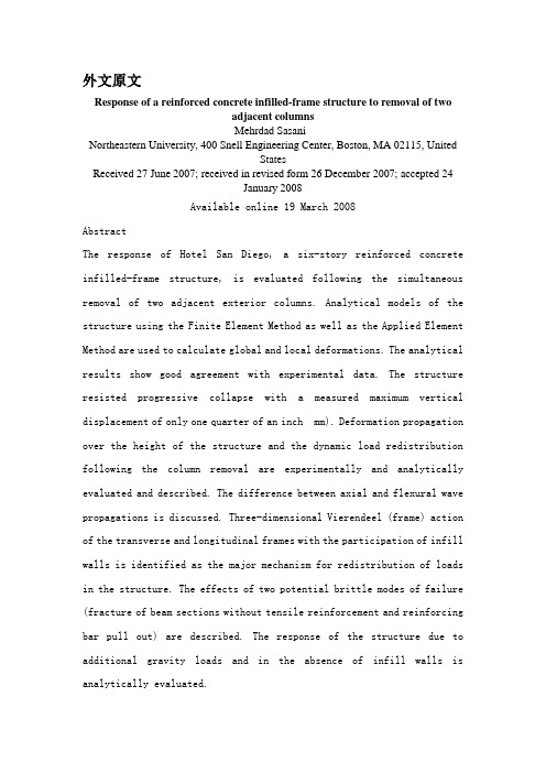
外文原文Response of a reinforced concrete infilled-frame structure to removal of twoadjacent columnsMehrdad Sasani_Northeastern University, 400 Snell Engineering Center, Boston, MA 02115, UnitedStatesReceived 27 June 2007; received in revised form 26 December 2007; accepted 24January 2008Available online 19 March 2008AbstractThe response of Hotel San Diego, a six-story reinforced concrete infilled-frame structure, is evaluated following the simultaneous removal of two adjacent exterior columns. Analytical models of the structure using the Finite Element Method as well as the Applied Element Method are used to calculate global and local deformations. The analytical results show good agreement with experimental data. The structure resisted progressive collapse with a measured maximum vertical displacement of only one quarter of an inch mm). Deformation propagation over the height of the structure and the dynamic load redistribution following the column removal are experimentally and analytically evaluated and described. The difference between axial and flexural wave propagations is discussed. Three-dimensional Vierendeel (frame) action of the transverse and longitudinal frames with the participation of infill walls is identified as the major mechanism for redistribution of loads in the structure. The effects of two potential brittle modes of failure (fracture of beam sections without tensile reinforcement and reinforcing bar pull out) are described. The response of the structure due to additional gravity loads and in the absence of infill walls is analytically evaluated.c 2008 Elsevier Ltd. All rights reserved.Keywords: Progressive collapse; Load redistribution; Load resistance; Dynamic response; Nonlinear analysis; Brittle failure1.IntroductionThe principal scope of specifications is to provide general principles and computational methods in order to verify safet y of structures. The “safety factor ”, which according t o modern trends is independent of the nature and combination of the materials used, can usually be defined as the rati o between the conditions. This ratio is also proportional to the inverse of the probability ( risk ) of failure of th e structure.Failure has to be considered not only as overall collapse o f the structure but also as unserviceability or, according t o a more precise. Common definition. As the reaching of a “limit state ”which causes the construction not to acco mplish the task it was designed for. There are two categori es of limit state :(1)Ultimate limit sate, which corresponds to the highest value of the load-bearing capacity. Examples include local buckli ng or global instability of the structure; failure of some sections and subsequent transformation of the structure intoa mechanism; failure by fatigue; elastic or plastic deformati on or creep that cause a substantial change of the geometry of the structure; and sensitivity of the structure to alte rnating loads, to fire and to explosions.(2)Service limit states, which are functions of the use and durability of the structure. Examples include excessive defo rmations and displacements without instability; early or exces sive cracks; large vibrations; and corrosion.Computational methods used to verify structures with respect to the different safety conditions can be separated into: (1)Deterministic methods, in which the main parameters are co nsidered as nonrandom parameters.(2)Probabilistic methods, in which the main parameters are co nsidered as random parameters.Alternatively, with respect to the different use of factors of safety, computational methods can be separated into:(1)Allowable stress method, in which the stresses computed un der maximum loads are compared with the strength of the mat erial reduced by given safety factors.(2)Limit states method, in which the structure may be propor tioned on the basis of its maximum strength. This strength, as determined by rational analysis, shall not be less than that required to support a factored load equal to the sum of the factored live load and dead load ( ultimate state ).The stresses corresponding to working ( service ) conditions with unfactored live and dead loads are compared with pres cribed values ( service limit state ) . From the four poss ible combinations of the first two and second two methods, we can obtain some useful computational methods. Generally, t wo combinations prevail:(1)deterministic methods, which make use of allowable stresses . (2)Probabilistic methods, which make use of limit states. The main advantage of probabilistic approaches is that, at l east in theory, it is possible to scientifically take into account all random factors of safety, which are then combine d to define the safety factor. probabilistic approaches depend upon :(1) Random distribution of strength of materials with respect to the conditions of fabrication and erection ( scatter of the values of mechanical properties through out the structu re ); (2) Uncertainty of the geometry of the cross-section sand of the structure ( faults and imperfections due to fab rication and erection of the structure );(3) Uncertainty of the predicted live loads and dead loads acting on the structure; (4)Uncertainty related to the approx imation of the computational method used ( deviation of the actual stresses from computed stresses ). Furthermore, proba bilistic theories mean that the allowable risk can be based on several factors, such as :(1) Importance of the construction and gravity of the damage by its failure; (2)Number of human lives which can be thr eatened by this failure; (3)Possibility and/or likelihood of repairing the structure; (4) Predicted life of the structure. All these factors are related to economic and social consi derations such as:(1) Initial cost of the construction;(2) Amortization funds for the duration of the construction;(3) Cost of physical and material damage due to the failure of the construction;(4) Adverse impact on society;(5) Moral and psychological views.The definition of all these parameters, for a given saf ety factor, allows construction at the optimum cost. However, the difficulty of carrying out a complete probabilistic ana lysis has to be taken into account. For such an analysis t he laws of the distribution of the live load and its induc ed stresses, of the scatter of mechanical properties of mate rials, and of the geometry of the cross-sections and the st ructure have to be known. Furthermore, it is difficult to i nterpret the interaction between the law of distribution of strength and that of stresses because both depend upon the nature of the material, on the cross-sections and upon the load acting on the structure. These practical difficulties ca n be overcome in two ways. The first is to apply different safety factors to the material and to the loads, without necessarily adopting the probabilistic criterion. The second i s an approximate probabilistic method which introduces some s implifying assumptions ( semi-probabilistic methods ) . Aspart of mitigation programs to reduce the likelihood of mass casualties following local damage in structures, the General Services Administration [1] and the Department of Defense [2] developed regulations to evaluate progressive collapse resistance of structures. ASCE/SEI 7 [3] defines progressive collapse as the spread of an initial local failure fromelement to element eventually resulting in collapse of an entire structure or a disproportionately large part of it. Following the approaches proposed by Ellinwood and Leyendecker [4], ASCE/SEI 7 [3] defines two general methods for structural design of buildings to mitigate damage due to progressive collapse: indirect and direct design methods. General building codes and standards [3,5] use indirect design by increasing overall integrity of structures. Indirect design is also used in DOD [2]. Although the indirect design method can reduce the risk of progressive collapse [6,7] estimation of post-failure performance of structures designed based on such a method is not readily possible. One approach based on direct design methods to evaluate progressive collapse of structures is to study the effects of instantaneous removal of load-bearing elements, such as columns. GSA [1] and DOD [2] regulations require removal of one load bearing element. These regulations are meant to evaluate general integrity of structures and their capacity of redistributing the loads following severe damage to only one element. While such an approach provides insight as to the extent to which the structures are susceptible to progressive collapse, in reality, the initial damage can affect more than just one column. In this study, using analytical results that are verified against experimental data, the progressive collapse resistance of the Hotel San Diego is evaluated, following the simultaneous explosion (sudden removal) of two adjacent columns, one of which was a corner column. In order to explode the columns, explosives were inserted into predrilled holes in the columns. The columns were then well wrapped with a few layers of protective materials. Therefore, neither air blast nor flying fragments affected the structure.2. Building characteristicsHotel San Diego was constructed in 1914 with a south annex added in 1924. The annex included two separate buildings. Fig. 1 shows a south view of the hotel. Note that in the picture, the first and third stories of the hotel are covered with black fabric. The six story hotel had a non-ductile reinforced concrete (RC) frame structure with hollow clay tile exterior infill walls. The infills in the annex consisted of two withes (layers) of clay tiles with a total thickness of about 8 in (203 mm). The height of the first floor was about 190–800 m). The height of other floors and that of the top floor were 100–600 m) and 160–1000 m), respectively. Fig. 2 shows the second floor of one of the annex buildings. Fig. 3 shows a typical plan of this building, whose responsefollowing the simultaneous removal (explosion) of columns A2 and A3 in the first (ground) floor is evaluated in this paper. The floor system consisted of one-way joists running in the longitudinal direction (North–South), as shown in Fig. 3. Based on compression tests of two concrete samples, the average concrete compressive strength was estimated at about 4500 psi (31 MPa) for a standard concrete cylinder. The modulus of elasticity of concrete was estimated at 3820 ksi (26 300 MPa) [5]. Also, based on tension tests of two steel samples having 1/2 in mm) square sections, the yield and ultimate tensile strengths were found to be 62 ksi (427 MPa) and 87 ksi (600 MPa), respectively. The steel ultimate tensile strain was measured at . The modulus of elasticity of steel was set equal to 29 000 ksi (200 000 MPa). The building was scheduled to be demolished by implosion. As part of the demolition process, the infill walls were removed from the first and third floors. There was no live load in the building. All nonstructural elements including partitions, plumbing, and furniture were removed prior to implosion. Only beams, columns, joist floor and infill walls on the peripheral beams were present.3. SensorsConcrete and steel strain gages were used to measure changes in strains of beams and columns. Linear potentiometers were used to measure global and local deformations. The concrete strain gages were in (90 mm) long having a maximum strain limit of ±. The steel strain gages could measure up to a strain of ±. The strain gages could operate up to a several hundred kHz sampling rate. The sampling rate used in the experiment was 1000 Hz. Potentiometers were used to capture rotation (integral of curvature over a length) of the beam end regions and global displacementin the building, as described later. The potentiometers had a resolution of about in mm) and a maximum operational speed of about 40 in/s m/s), while the maximum recorded speed in the experiment was about 14 in/sm/s).4. Finite element modelUsing the finite element method (FEM), a model of the building was developed in the SAP2000 [8] computer program. The beams and columns are modeled with Bernoulli beam elements. Beams have T or L sections with effective flange width on each side of the web equal to four times the slab thickness [5]. Plastic hinges are assigned to all possible locations where steel bar yielding can occur, including the ends of elements as well as the reinforcing bar cut-off and bend locations. The characteristics of the plastic hinges are obtained using section analysesof the beams and columns and assuming a plastic hinge length equal to half of the section depth. The current version of SAP2000 [8] is not able to track formation of cracks in the elements. In order to find the proper flexural stiffness of sections, an iterative procedure is used as follows. First, the building is analyzed assuming all elements are uncracked. Then, moment demands in the elements are compared with their cracking bending moments, Mcr . The moment of inertia of beam and slab segments are reduced by a coefficient of [5], where the demand exceeds the Mcr. The exterior beam cracking bending moments under negative and positive moments, are 516 k in kN m) and 336 k in kN m), respectively. Note that no cracks were formed in the columns. Then the building is reanalyzed and moment diagrams are re-evaluated. This procedure is repeated until all of the cracked regions are properly identified and modeled.The beams in the building did not have top reinforcing bars except at the end regions (see Fig. 4). For instance, no top reinforcement was provided beyond the bend in beam A1–A2, 12 inches away from the face of column A1 (see Figs. 4 and 5). To model the potential loss of flexural strength in those sections, localized crack hinges were assigned at the critical locations where no top rebar was present. Flexural strengths of the hinges were set equal to Mcr. Such sections were assumed to lose their flexural strength when the imposed bending moments reached Mcr.The floor system consisted of joists in the longitudinal direction (North–South). Fig. 6 shows the cross section of a typical floor. In order to account for potential nonlinear response of slabs and joists, floors are molded by beam elements. Joists are modeled with T-sections, having effective flange width on each side of the web equal to four times the slab thickness [5]. Given the large joist spacing between axes 2 and 3, two rectangular beam elements with 20-inch wide sections are used between the joist and the longitudinal beams of axes 2 and 3 to model the slab in the longitudinal direction. To model the behavior of the slab in the transverse direction, equally spaced parallel beams with 20-inch wide rectangular sections are used. There is a difference between the shear flow in the slab and that in the beam elements with rectangular sections modeling the slab. Because of this, the torsional stiffness is setequal to one-half of that of the gross sections [9].The building had infill walls on 2nd, 4th, 5th and 6th floors on the spandrel beams with some openings . windows and doors). As mentioned before and as part of the demolition procedure, the infill walls in the 1st and 3rd floors were removed before the test. The infill walls were made of hollow clay tiles, which were in good condition. The net area of the clay tiles was about 1/2 of the gross area. The in-plane action of the infill walls contributes to the building stiffness and strength and affects the building response. Ignoring the effects of the infill walls and excluding them in the model would result in underestimating the building stiffness and strength.Using the SAP2000 computer program [8], two types of modeling for the infills are considered in this study: one uses two dimensional shell elements (Model A) and the other uses compressive struts (Model B) as suggested in FEMA356 [10] guidelines.. Model A (infills modeled by shell elements)Infill walls are modeled with shell elements. However, the current version of the SAP2000 computer program includes only linear shell elements and cannot account for cracking. The tensile strength of the infill walls is set equal to 26 psi, with a modulus of elasticity of 644 ksi [10]. Because the formation ofcracks has a significant effect on the stiffness of the infill walls, the following iterative procedure is used to account for crack formation:(1) Assuming the infill walls are linear and uncracked, a nonlinear time history analysis is run. Note that plastic hinges exist in the beam elements and the segments of the beam elements where moment demand exceeds the cracking moment have a reduced moment of inertia.(2) The cracking pattern in the infill wall is determined by comparingstresses in the shells developed during the analysis with the tensile strength of infills.(3) Nodes are separated at the locations where tensile stress exceeds tensile strength. These steps are continued until the crack regions are properly modeled.. Model B (infills modeled by struts)Infill walls are replaced with compressive struts as described in FEMA 356 [10] guidelines. Orientations of the struts are determined from the deformed shape of the structure after column removal and the location of openings.. Column removalRemoval of the columns is simulated with the following procedure. (1) The structure is analyzed under the permanent loads and the internal forces are determined at the ends of the columns, which will be removed.(2) The model is modified by removing columns A2 and A3 on the first floor. Again the structure is statically analyzed under permanent loads. In this case, the internal forces at the ends of removed columns found in the first step are applied externally to the structure along with permanent loads. Note that the results of this analysis are identical to those of step 1.(3) The equal and opposite column end forces that were applied in the second step are dynamically imposed on the ends of the removed column within one millisecond [11] to simulate the removal of the columns, and dynamic analysis is conducted.. Comparison of analytical and experimental resultsThe maximum calculated vertical displacement of the building occurs at joint A3 in the second floor. Fig. 7 shows the experimental andanalytical (Model A) vertical displacements of this joint (the AEM results will be discussed in the next section). Experimental data is obtained using the recordings of three potentiometers attached to joint A3 on one of their ends, and to the ground on the other ends. The peak displacements obtained experimentally and analytically (Model A) are in mm) and in mm), respectively, which differ only by about 4%. The experimental and analytical times corresponding to peak displacement are s and s, respectively. The analytical results show a permanent displacement of about in mm), which is about 14% smaller than the corresponding experimental value of in mm).Fig. 8 compares vertical displacement histories of joint A3 in the second floor estimated analytically based on Models A and B. As can be seen, modeling infills with struts (Model B) results in a maximum vertical displacement of joint A3 equal to about in mm), which is approximately 80% larger than the value obtained from Model A. Note that the results obtained from Model A are in close agreement with experimental results (see Fig. 7), while Model B significantly overestimates the deformation of the structure. If the maximum vertical displacement were larger, the infill walls were more severely cracked and the struts were more completely formed, the difference between the results of the two models (Models A and B) would be smaller.Fig. 9 compares the experimental and analytical (Model A) displacement of joint A2 in the second floor. Again, while the first peak vertical displacement obtained experimentally and analytically are in good agreement, the analytical permanent displacement under estimates the experimental value.Analytically estimated deformed shapes of the structure at the maximumvertical displacement based on Model A are shown in Fig. 10 with a magnification factor of 200. The experimentally measured deformed shape over the end regions of beams A1–A2 and A3–B3 in the second floorare represented in the figure by solid lines. A total of 14 potentiometers were located at the top and bottom of the end regions of the second floor beams A1–A2 and A3–B3, which were the most critical elements in load redistribution. The beam top and corresponding bottom potentiometerrecordings were used to calculate rotation between the sections where the potentiometer ends were connected. This was done by first finding the difference between the recorded deformations at the top and bottom of the beam, and then dividing the value by the distance (along the height of the beam section) between the two potentiometers. The expected deformed shapes between the measured end regions of the second floor beams are shown by dashed lines. As can be seen in the figures, analytically estimated deformed shapes of the beams are in good agreement with experimentally obtained deformed shapes.Analytical results of Model A show that only two plastic hinges are formed indicating rebar yielding. Also, four sections that did not have negative (top) reinforcement, reached cracking moment capacities and therefore cracked. Fig. 10 shows the locations of all the formed plastic hinges and cracks.。
一、外文原文Talling building and Steel construction Although there have been many advancements in building construction technology in general. Spectacular archievements have been made in the design and construction of ultrahigh-rise buildings.The early development of high-rise buildings began with structural steel framing.Reinforced concrete and stressed-skin tube systems have since been economically and competitively used in a number of structures for both residential and commercial purposes.The high-rise buildings ranging from 50 to 110 stories that are being built all over the United States are the result of innovations and development of new structual systems.Greater height entails increased column and beam sizes to make buildings more rigid so that under wind load they will not sway beyond an acceptable limit.Excessive lateral sway may cause serious recurring damage to partitions,ceilings.and other architectural details. In addition,excessive sway may cause discomfort to the occupants of the building because their perception of such motion.Structural systems of reinforced concrete,as well as steel,take full advantage of inherent potential stiffness of the total building and therefore require additional stiffening to limit the sway.In a steel structure,for example,the economy can be defined in terms of the total average quantity of steel per square foot of floor area of the building.Curve A in Fig .1 represents the average unit weight of a conventional frame with increasing numbers of stories. Curve B represents the average steel weight if the frame is protected from all lateral loads. The gap between the upper boundary and the lower boundary represents the premium for height for the traditional column-and-beam frame.Structural engineers have developed structural systems with a view to eliminating this premium.Systems in steel. Tall buildings in steel developed as a result ofseveral types of structural innovations. The innovations have been applied to the construction of both office and apartment buildings.Frame with rigid belt trusses. In order to tie the exterior columns of a frame structure to the interior vertical trusses,a system of rigid belt trusses at mid-height and at the top of the building may be used. A good example of this system is the First Wisconsin Bank Building(1974) in Milwaukee.Framed tube. The maximum efficiency of the total structure of a tall building, for both strength and stiffness,to resist wind load can be achieved only if all column element can be connected to each other in such a way that the entire building acts as a hollow tube or rigid box in projecting out of the ground. This particular structural system was probably used for the first time in the 43-story reinforced concrete DeWitt Chestnut Apartment Building in Chicago. The most significant use of this system is in the twin structural steel towers of the 110-story World Trade Center building in New York Column-diagonal truss tube. The exterior columns of a building can be spaced reasonably far apart and yet be made to work together as a tube by connecting them with diagonal members interesting at the centre line of the columns and beams. This simple yet extremely efficient system was used for the first time on the John Hancock Centre in Chicago, using as much steel as is normally needed for a traditional 40-story building.Bundled tube. With the continuing need for larger and taller buildings, the framed tube or the column-diagonal truss tube may be used in a bundled form to create larger tube envelopes while maintaining high efficiency. The 110-story Sears Roebuck Headquarters Building in Chicago has nine tube, bundled at the base of the building in three rows. Some of these individual tubes terminate at different heights of the building, demonstrating the unlimited architectural possibilities of this latest structural concept. The Sears tower, at a height of 1450 ft(442m), is the world’s tallest building.Stressed-skin tube system. The tube structural system was developed for improving the resistance to lateral forces (wind and earthquake) and thecontrol of drift (lateral building movement ) in high-rise building. The stressed-skin tube takes the tube system a step further. The development of the stressed-skin tube utilizes the façade of the building as a structural element which acts with the framed tube, thus providing an efficient way of resisting lateral loads in high-rise buildings, and resulting in cost-effective column-free interior space with a high ratio of net to gross floor area.Because of the contribution of the stressed-skin façade, the framed members of the tube require less mass, and are thus lighter and less expensive. All the typical columns and spandrel beams are standard rolled shapes,minimizing the use and cost of special built-up members. The depth requirement for the perimeter spandrel beams is also reduced, and the need for upset beams above floors, which would encroach on valuable space, is minimized. The structural system has been used on the 54-story One Mellon Bank Center in Pittburgh.Systems in concrete. While tall buildings constructed of steel had an early start, development of tall buildings of reinforced concrete progressed at a fast enough rate to provide a competitive chanllenge to structural steel systems for both office and apartment buildings.Framed tube. As discussed above, the first framed tube concept for tall buildings was used for the 43-story DeWitt Chestnut Apartment Building. In this building ,exterior columns were spaced at 5.5ft (1.68m) centers, and interior columns were used as needed to support the 8-in . -thick (20-m) flat-plate concrete slabs.Tube in tube. Another system in reinforced concrete for office buildings combines the traditional shear wall construction with an exterior framed tube. The system consists of an outer framed tube of very closely spaced columns and an interior rigid shear wall tube enclosing the central service area. The system known as the tube-in-tube system , made it possible to design the world’s present tallest (714ft or 218m)lightweight concrete bu ilding( the 52-story One Shell Plaza Building in Houston) for the unit price of a traditional shear wall structure of only 35 stories.Systems combining both concrete and steel have also been developed, an examle of which is the composite system developed by skidmore, Owings &Merril in which an exterior closely spaced framed tube in concrete envelops an interior steel framing, thereby combining the advantages of both reinforced concrete and structural steel systems. The 52-story One Shell Square Building in New Orleans is based on this system.Steel construction refers to a broad range of building construction in which steel plays the leading role. Most steel construction consists of large-scale buildings or engineering works, with the steel generally in the form of beams, girders, bars, plates, and other members shaped through the hot-rolled process. Despite the increased use of other materials, steel construction remained a major outlet for the steel industries of the U.S, U.K, U.S.S.R, Japan, West German, France, and other steel producers in the 1970s.二、原文翻译高层结构与钢结构近年来,尽管一般的建筑结构设计取得了很大的进步,但是取得显著成绩的还要属超高层建筑结构设计。
土木工程专业常用英语词汇第一节普通术语3. 房屋建造工程building engineering4. 土木工程civil engineering除房屋建造外,为新建、改建或扩建各类工程的建造物、构筑物和相关配套设施等所举行的勘察、计划、设计、施工、安装和维护等各项技术工作和完成的工程实体。
5. 马路工程highway engineering10. 建造物(构筑物)construction works房屋建造或土木工程中的单项工程实体。
11. 结构structure12. 基础foundation13. 地基foundation soil; subgrade; subbase; ground14. 木结构timber structure16. 钢结构steel structure17. 混凝土(砼)结构concrete structure18. 特种工程结构special engineering structure22. 马路highway24. 高速马路freeway27. 铁路(铁道)railway; railroad28. 标准轨距铁路standard gauge railway29. 宽轨距铁路broad gauge railway第四节桥、涵洞和隧道术语1. 桥bridge2. 简支梁桥simple supported girder bridge3. 延续梁桥continuous girder bridge5. 斜拉(斜张)桥cable stayed bridge6. 悬索(吊)桥suspension bridge7. 桁架桥trussed bridge9.刚构(刚架)桥rigid frame bridge10.拱桥arch bridge13.正交桥right bridge14.斜交桥skew bridge16.高架桥viaduct17.正(主)桥main span18.引桥approach span19.弯桥curved bridge21.马路铁路两用桥combined bridge; highway and railway transit bridge 25.桥跨结构(上部结构)bridge superstructure26.桥面系bridge floor system27.桥支座bridge bearing; bridge support28.桥下部结构bridge substructure29.索塔(桥塔)bridge tower30.桥台abutment31.桥墩pier32.涵洞culvert第六节结构构件和部件术语1.构件member2.部件component; assembly parts3.截面section4.梁beam; girder5.拱arch6.板slab; plate8.柱column10.桁架truss11.框架frame12.排架bent frame13.刚架(刚构)rigid frame14.简支梁simply supported beam15.悬臂梁cantilever beam16.两端固定梁beam fixed at both ends17.延续梁continuous beam19.桩pile20.板桩sheet pile34. 钢轨rail第七节地基和基础术语1. 扩展(扩大)基础spread foundation2. 刚性基础rigid foundation3. 自立基础single footing4. 联合基础combined footing5. 条形基础strip foundation6. 壳体基础shell foundation7. 箱形基础box foundation8. 筏形基础raft foundation9. 桩基础pile foundation10. 沉井基础open caisson foundation11. 管柱基础cylinder pile foundation ; cylinder caisson foundation12. 沉箱基础caisson foundation1. 可靠性reliability2. 安全性safety3. 适用性serviceability4. 耐久性durability5. 基本变量basic variable6. 设计基准期design reference period7. 可靠概率probability of survival8. 失效概率probability of failure9. 可靠指标reliability index12. 概率设计法probabilistic method13. 容许应力设计法permissible (allowable) stresses method14. 破坏强度设计法ultimate strength method15. 极限状态设计法limit states method16. 极限状态limit states17. 极限状态方程limit state equation18. 承载能力极限状态ultimate limit states19. 正常使用极限状态serviceability limit states20. 分项系数partial safety factor21. 设计情况design situation22. 持久情况persistent situation23. 短暂情况transient situation24. 偶尔情况accidental situation1. 作用action2. 荷载load3. 线分布力force per unit length4. 面分布力force per unit area5. 体分布力force per unit volume6. 力矩moment of force7. 永远作用permanent action8. 可变作用variable action9. 偶尔作用accidental action10.固定作用fixed adtion11.自由(可动)作用. Free action12. 静态作用static action13. 动态作用dynamic action14. 多次重复作用repeated action; cyclic action16. 自重self weight17. 施工荷载site load18. 土压力earth pressure19. 温度作用temperature action20. 地震作用earthquake action22.风荷载wind load23.风振wind vibration24. 雪荷载snow load27.桥(桥梁)荷载load on bridge28.桥(桥梁)恒荷载dead load on bridge29.桥(桥梁)活荷载live load on bridge30.马路车辆荷载标准Standard highway vehicle load31.中国铁路标准活载Standard Railway Live Load Specified by the People’sRepublic of China44.作用代表值representative value of an action45.作用标准值characteristic value of an action46.作用准永远值quasi-permanent value of an action47.作用组合值combination value of actions48.作用分项系数partial safety factor for action49.作用设计值design value of an action50.作用组合值系数coeffcient for combination value of actions 51.作用效应effects of actions52.作用效应系数coefficient of effects of actions53.轴向力normal force\axial force54.剪力shear force55.弯矩bending moment57.扭矩torque58.应力stress59.正应力normal stress60.剪应力shear stress; tangential stress61.主应力principal stress62.预应力prestress63.位移displacement64.挠度deflection65.变形deformation66.弹性变形elastic deformation67.塑性变形plastic deformation70.应变strain71.线应变linear strain72.剪应变shear strain; tangential strain73.主应变principal strain74.作用效应组合combination for action effects75.作用效应基本组合fundamental combination for action effects 77.短期效应组合combination for short-term action effects 78.持久效应组合combination for long-term action effects 79.设计限值limiting design value1.抗力resistance2.强度strength3.抗压强度compressive strength4.抗拉强度tensile strength5.抗剪强度shear strength6.抗弯强度flexural strength7.屈服强度yield strength8.疲劳强度fatigue strength9.极限应变ultimate strain10.弹性模量modulus of elasticity11.剪变模量shear modulus12.变形模量modulus of deformation13.泊松比Poisson ratio14.承载能力bearing capacity15.受压承载能力compressive capacity16.受拉承载能力tensile capacity17.受剪承载能力shear capacity18.受弯承载能力flexural capacity19.受扭承载能力torsional capacity20.疲劳承载能力fatigue capacity21.刚度stiffness; rigidity22.抗裂度crack resistance23.极限变形ultimate deformation24.稳定性stability26.脆性破坏brittle failure27.延性破坏ductile failure30.材料性能分项系数partial safety factor for property of material。
土木工程专业外语词汇大全中英翻译1. 综合类大地工程geotechnical engineering1. 综合类反分析法back analysis method1. 综合类基础工程foundation engineering1. 综合类临界状态土力学critical state soil mechanics1. 综合类数值岩土力学numerical geomechanics1. 综合类土soil, earth1. 综合类土动力学soil dynamics1. 综合类土力学soil mechanics1. 综合类岩土工程geotechnical engineering1. 综合类应力路径stress path1. 综合类应力路径法stress path method2. 工程地质及勘察变质岩metamorphic rock2. 工程地质及勘察标准冻深standard frost penetration2. 工程地质及勘察冰川沉积glacial deposit2. 工程地质及勘察冰积层(台)glacial deposit2. 工程地质及勘察残积土eluvial soil, residual soil2. 工程地质及勘察层理beding2. 工程地质及勘察长石feldspar2. 工程地质及勘察沉积岩sedimentary rock2. 工程地质及勘察承压水confined water2. 工程地质及勘察次生矿物secondary mineral2. 工程地质及勘察地质年代geological age2. 工程地质及勘察地质图geological map2. 工程地质及勘察地下水groundwater2. 工程地质及勘察断层fault2. 工程地质及勘察断裂构造fracture structure2. 工程地质及勘察工程地质勘察engineering geological exploration 2. 工程地质及勘察海积层(台)marine deposit2. 工程地质及勘察海相沉积marine deposit2. 工程地质及勘察花岗岩granite2. 工程地质及勘察滑坡landslide2. 工程地质及勘察化石fossil2. 工程地质及勘察化学沉积岩chemical sedimentary rock2. 工程地质及勘察阶地terrace2. 工程地质及勘察节理joint2. 工程地质及勘察解理cleavage2. 工程地质及勘察喀斯特karst2. 工程地质及勘察矿物硬度hardness of minerals2. 工程地质及勘察砾岩conglomerate2. 工程地质及勘察流滑flow slide2. 工程地质及勘察陆相沉积continental sedimentation2. 工程地质及勘察泥石流mud flow, debris flow2. 工程地质及勘察年粘土矿物clay minerals2. 工程地质及勘察凝灰岩tuff2. 工程地质及勘察牛轭湖ox-bow lake2. 工程地质及勘察浅成岩hypabyssal rock2. 工程地质及勘察潜水ground water2. 工程地质及勘察侵入岩intrusive rock2. 工程地质及勘察取土器geotome2. 工程地质及勘察砂岩sandstone2. 工程地质及勘察砂嘴spit, sand spit2. 工程地质及勘察山岩压力rock pressure2. 工程地质及勘察深成岩plutionic rock2. 工程地质及勘察石灰岩limestone2. 工程地质及勘察石英quartz2. 工程地质及勘察松散堆积物rickle2. 工程地质及勘察围限地下水(台)confined ground water 2. 工程地质及勘察泻湖lagoon2. 工程地质及勘察岩爆rock burst2. 工程地质及勘察岩层产状attitude of rock2. 工程地质及勘察岩浆岩magmatic rock, igneous rock2. 工程地质及勘察岩脉dike, dgke2. 工程地质及勘察岩石风化程度degree of rock weathering 2. 工程地质及勘察岩石构造structure of rock2. 工程地质及勘察岩石结构texture of rock2. 工程地质及勘察岩体rock mass2. 工程地质及勘察页岩shale2. 工程地质及勘察原生矿物primary mineral2. 工程地质及勘察云母mica2. 工程地质及勘察造岩矿物rock-forming mineral2. 工程地质及勘察褶皱fold, folding2. 工程地质及勘察钻孔柱状图bore hole columnar section3. 土的分类饱和土saturated soil3. 土的分类超固结土overconsolidated soil3. 土的分类冲填土dredger fill3. 土的分类充重塑土3. 土的分类冻土frozen soil, tjaele3. 土的分类非饱和土unsaturated soil3. 土的分类分散性土dispersive soil3. 土的分类粉土silt, mo3. 土的分类粉质粘土silty clay3. 土的分类高岭石kaolinite3. 土的分类过压密土(台)overconsolidated soil3. 土的分类红粘土red clay, adamic earth3. 土的分类黄土loess, huangtu(China)3. 土的分类蒙脱石montmorillonite3. 土的分类泥炭peat, bog muck3. 土的分类年粘土clay3. 土的分类年粘性土cohesive soil, clayey soil3. 土的分类膨胀土expansive soil, swelling soil3. 土的分类欠固结粘土underconsolidated soil3. 土的分类区域性土zonal soil3. 土的分类人工填土fill, artificial soil3. 土的分类软粘土soft clay, mildclay, mickle3. 土的分类砂土sand3. 土的分类湿陷性黄土collapsible loess, slumping loess3. 土的分类素填土plain fill3. 土的分类塑性图plasticity chart3. 土的分类碎石土stone, break stone, broken stone, channery, chat, crushed stone, deritus 3. 土的分类未压密土(台)underconsolidated clay3. 土的分类无粘性土cohesionless soil, frictional soil, non-cohesive soil3. 土的分类岩石rock3. 土的分类伊利土illite3. 土的分类有机质土organic soil3. 土的分类淤泥muck, gyttja, mire, slush3. 土的分类淤泥质土mucky soil3. 土的分类原状土undisturbed soil3. 土的分类杂填土miscellaneous fill3. 土的分类正常固结土normally consolidated soil3. 土的分类正常压密土(台)normally consolidated soil3. 土的分类自重湿陷性黄土self weight collapse loess4. 土的物理性质阿太堡界限Atterberg limits4. 土的物理性质饱和度degree of saturation4. 土的物理性质饱和密度saturated density4. 土的物理性质饱和重度saturated unit weight4. 土的物理性质比重specific gravity4. 土的物理性质稠度consistency4. 土的物理性质不均匀系数coefficient of uniformity, uniformity coefficient4. 土的物理性质触变thixotropy4. 土的物理性质单粒结构single-grained structure4. 土的物理性质蜂窝结构honeycomb structure4. 土的物理性质干重度dry unit weight4. 土的物理性质干密度dry density4. 土的物理性质塑性指数plasticity index4. 土的物理性质含水量water content, moisture content4. 土的物理性质活性指数4. 土的物理性质级配gradation, grading4. 土的物理性质结合水bound water, combined water, held water4. 土的物理性质界限含水量Atterberg limits4. 土的物理性质颗粒级配particle size distribution of soils, mechanical composition of soil 4. 土的物理性质可塑性plasticity4. 土的物理性质孔隙比void ratio4. 土的物理性质孔隙率porosity4. 土的物理性质粒度granularity, grainness, grainage4. 土的物理性质粒组fraction, size fraction4. 土的物理性质毛细管水capillary water4. 土的物理性质密度density4. 土的物理性质密实度compactionness4. 土的物理性质年粘性土的灵敏度sensitivity of cohesive soil4. 土的物理性质平均粒径mean diameter, average grain diameter4. 土的物理性质曲率系数coefficient of curvature4. 土的物理性质三相图block diagram, skeletal diagram, three phase diagram4. 土的物理性质三相土tri-phase soil4. 土的物理性质湿陷起始应力initial collapse pressure4. 土的物理性质湿陷系数coefficient of collapsibility4. 土的物理性质缩限shrinkage limit4. 土的物理性质土的构造soil texture4. 土的物理性质土的结构soil structure4. 土的物理性质土粒相对密度specific density of solid particles4. 土的物理性质土中气air in soil4. 土的物理性质土中水water in soil4. 土的物理性质团粒aggregate, cumularpharolith4. 土的物理性质限定粒径constrained diameter4. 土的物理性质相对密度relative density, density index4. 土的物理性质相对压密度relative compaction, compacting factor, percent compaction, coefficient of compaction4. 土的物理性质絮状结构flocculent structure4. 土的物理性质压密系数coefficient of consolidation4. 土的物理性质压缩性compressibility4. 土的物理性质液限liquid limit4. 土的物理性质液性指数liquidity index4. 土的物理性质游离水(台)free water4. 土的物理性质有效粒径effective diameter, effective grain size, effective size4. 土的物理性质有效密度effective density4. 土的物理性质有效重度effective unit weight4. 土的物理性质重力密度unit weight4. 土的物理性质自由水free water, gravitational water, groundwater, phreatic water4. 土的物理性质组构fabric4. 土的物理性质最大干密度maximum dry density4. 土的物理性质最优含水量optimum water content5. 渗透性和渗流达西定律Darcy s law5. 渗透性和渗流管涌piping5. 渗透性和渗流浸润线phreatic line5. 渗透性和渗流临界水力梯度critical hydraulic gradient5. 渗透性和渗流流函数flow function5. 渗透性和渗流流土flowing soil5. 渗透性和渗流流网flow net5. 渗透性和渗流砂沸sand boiling5. 渗透性和渗流渗流seepage5. 渗透性和渗流渗流量seepage discharge5. 渗透性和渗流渗流速度seepage velocity5. 渗透性和渗流渗透力seepage force5. 渗透性和渗流渗透破坏seepage failure5. 渗透性和渗流渗透系数coefficient of permeability5. 渗透性和渗流渗透性permeability5. 渗透性和渗流势函数potential function5. 渗透性和渗流水力梯度hydraulic gradient6. 地基应力和变形变形deformation6. 地基应力和变形变形模量modulus of deformation6. 地基应力和变形泊松比Poisson s ratio6. 地基应力和变形布西涅斯克解Boussinnesq s solution6. 地基应力和变形残余变形residual deformation6. 地基应力和变形残余孔隙水压力residual pore water pressure6. 地基应力和变形超静孔隙水压力excess pore water pressure6. 地基应力和变形沉降settlement6. 地基应力和变形沉降比settlement ratio6. 地基应力和变形次固结沉降secondary consolidation settlement6. 地基应力和变形次固结系数coefficient of secondary consolidation6. 地基应力和变形地基沉降的弹性力学公式elastic formula for settlement calculation 6. 地基应力和变形分层总和法layerwise summation method6. 地基应力和变形负孔隙水压力negative pore water pressure6. 地基应力和变形附加应力superimposed stress6. 地基应力和变形割线模量secant modulus6. 地基应力和变形固结沉降consolidation settlement6. 地基应力和变形规范沉降计算法settlement calculation by specification6. 地基应力和变形回弹变形rebound deformation6. 地基应力和变形回弹模量modulus of resilience6. 地基应力和变形回弹系数coefficient of resilience6. 地基应力和变形回弹指数swelling index6. 地基应力和变形建筑物的地基变形允许值allowable settlement of building6. 地基应力和变形剪胀dilatation6. 地基应力和变形角点法corner-points method6. 地基应力和变形孔隙气压力pore air pressure6. 地基应力和变形孔隙水压力pore water pressure6. 地基应力和变形孔隙压力系数Apore pressure parameter A6. 地基应力和变形孔隙压力系数Bpore pressure parameter B6. 地基应力和变形明德林解Mindlin s solution6. 地基应力和变形纽马克感应图Newmark chart6. 地基应力和变形切线模量tangent modulus6. 地基应力和变形蠕变creep6. 地基应力和变形三向变形条件下的固结沉降three-dimensional consolidation settlement 6. 地基应力和变形瞬时沉降immediate settlement6. 地基应力和变形塑性变形plastic deformation6. 地基应力和变形谈弹性变形elastic deformation6. 地基应力和变形谈弹性模量elastic modulus6. 地基应力和变形谈弹性平衡状态state of elastic equilibrium6. 地基应力和变形体积变形模量volumetric deformation modulus6. 地基应力和变形先期固结压力preconsolidation pressure6. 地基应力和变形压缩层6. 地基应力和变形压缩模量modulus of compressibility6. 地基应力和变形压缩系数coefficient of compressibility6. 地基应力和变形压缩性compressibility6. 地基应力和变形压缩指数compression index6. 地基应力和变形有效应力effective stress6. 地基应力和变形自重应力self-weight stress6. 地基应力和变形总应力total stress approach of shear strength6. 地基应力和变形最终沉降final settlement7. 固结巴隆固结理论Barron s consolidation theory7. 固结比奥固结理论Biot s consolidation theory7. 固结超固结比over-consolidation ratio7. 固结超静孔隙水压力excess pore water pressure7. 固结次固结secondary consolidation7. 固结次压缩(台)secondary consolidatin7. 固结单向度压密(台)one-dimensional consolidation7. 固结多维固结multi-dimensional consolidation7. 固结固结consolidation7. 固结固结度degree of consolidation7. 固结固结理论theory of consolidation7. 固结固结曲线consolidation curve7. 固结固结速率rate of consolidation7. 固结固结系数coefficient of consolidation7. 固结固结压力consolidation pressure7. 固结回弹曲线rebound curve7. 固结井径比drain spacing ratio7. 固结井阻well resistance7. 固结曼代尔-克雷尔效应Mandel-Cryer effect7. 固结潜变(台)creep7. 固结砂井sand drain7. 固结砂井地基平均固结度average degree of consolidation of sand-drained ground7. 固结时间对数拟合法logrithm of time fitting method7. 固结时间因子time factor7. 固结太沙基固结理论Terzaghi s consolidation theory7. 固结太沙基-伦杜列克扩散方程Terzaghi-Rendulic diffusion equation7. 固结先期固结压力preconsolidation pressure7. 固结压密(台)consolidation7. 固结压密度(台)degree of consolidation7. 固结压缩曲线cpmpression curve7. 固结一维固结one dimensional consolidation7. 固结有效应力原理principle of effective stress7. 固结预压密压力(台)preconsolidation pressure7. 固结原始压缩曲线virgin compression curve7. 固结再压缩曲线recompression curve7. 固结主固结primary consolidation7. 固结主压密(台)primary consolidation7. 固结准固结压力pseudo-consolidation pressure7. 固结K0固结consolidation under K0 condition8. 抗剪强度安息角(台)angle of repose8. 抗剪强度不排水抗剪强度undrained shear strength8. 抗剪强度残余内摩擦角residual angle of internal friction8. 抗剪强度残余强度residual strength8. 抗剪强度长期强度long-term strength8. 抗剪强度单轴抗拉强度uniaxial tension test8. 抗剪强度动强度dynamic strength of soils8. 抗剪强度峰值强度peak strength8. 抗剪强度伏斯列夫参数Hvorslev parameter8. 抗剪强度剪切应变速率shear strain rate8. 抗剪强度抗剪强度shear strength8. 抗剪强度抗剪强度参数shear strength parameter8. 抗剪强度抗剪强度有效应力法effective stress approach of shear strength 8. 抗剪强度抗剪强度总应力法total stress approach of shear strength8. 抗剪强度库仑方程Coulomb s equation8. 抗剪强度摩尔包线Mohr s envelope8. 抗剪强度摩尔-库仑理论Mohr-Coulomb theory8. 抗剪强度内摩擦角angle of internal friction8. 抗剪强度年粘聚力cohesion8. 抗剪强度破裂角angle of rupture8. 抗剪强度破坏准则failure criterion8. 抗剪强度十字板抗剪强度vane strength8. 抗剪强度无侧限抗压强度unconfined compression strength8. 抗剪强度有效内摩擦角effective angle of internal friction8. 抗剪强度有效粘聚力effective cohesion intercept8. 抗剪强度有效应力破坏包线effective stress failure envelope8. 抗剪强度有效应力强度参数effective stress strength parameter8. 抗剪强度有效应力原理principle of effective stress8. 抗剪强度真内摩擦角true angle internal friction8. 抗剪强度真粘聚力true cohesion8. 抗剪强度总应力破坏包线total stress failure envelope8. 抗剪强度总应力强度参数total stress strength parameter9. 本构模型本构模型constitutive model9. 本构模型边界面模型boundary surface model9. 本构模型层向各向同性体模型cross anisotropic model9. 本构模型超弹性模型hyperelastic model9. 本构模型德鲁克-普拉格准则Drucker-Prager criterion9. 本构模型邓肯-张模型Duncan-Chang model9. 本构模型动剪切强度9. 本构模型非线性弹性模量nonlinear elastic model9. 本构模型盖帽模型cap model9. 本构模型刚塑性模型rigid plastic model9. 本构模型割线模量secant modulus9. 本构模型广义冯·米赛斯屈服准则extended von Mises yield criterion 9. 本构模型广义特雷斯卡屈服准则extended tresca yield criterion9. 本构模型加工软化work softening9. 本构模型加工硬化work hardening9. 本构模型加工硬化定律strain harding law9. 本构模型剑桥模型Cambridge model9. 本构模型柯西弹性模型Cauchy elastic model9. 本构模型拉特-邓肯模型Lade-Duncan model9. 本构模型拉特屈服准则Lade yield criterion9. 本构模型理想弹塑性模型ideal elastoplastic model9. 本构模型临界状态弹塑性模型critical state elastoplastic model9. 本构模型流变学模型rheological model9. 本构模型流动规则flow rule9. 本构模型摩尔-库仑屈服准则Mohr-Coulomb yield criterion9. 本构模型内蕴时间塑性模型endochronic plastic model9. 本构模型内蕴时间塑性理论endochronic theory9. 本构模型年粘弹性模型viscoelastic model9. 本构模型切线模量tangent modulus9. 本构模型清华弹塑性模型Tsinghua elastoplastic model9. 本构模型屈服面yield surface9. 本构模型沈珠江三重屈服面模型Shen Zhujiang three yield surface method 9. 本构模型双参数地基模型9. 本构模型双剪应力屈服模型twin shear stress yield criterion9. 本构模型双曲线模型hyperbolic model9. 本构模型松岗元-中井屈服准则Matsuoka-Nakai yield criterion9. 本构模型塑性形变理论9. 本构模型谈弹塑性模量矩阵elastoplastic modulus matrix9. 本构模型谈弹塑性模型elastoplastic modulus9. 本构模型谈弹塑性增量理论incremental elastoplastic theory9. 本构模型谈弹性半空间地基模型elastic half-space foundation model9. 本构模型谈弹性变形elastic deformation9. 本构模型谈弹性模量elastic modulus9. 本构模型谈弹性模型elastic model9. 本构模型魏汝龙-Khosla-Wu模型Wei Rulong-Khosla-Wu model9. 本构模型文克尔地基模型Winkler foundation model9. 本构模型修正剑桥模型modified cambridge model9. 本构模型准弹性模型hypoelastic model10. 地基承载力冲剪破坏punching shear failure10. 地基承载力次层(台)substratum10. 地基承载力地基subgrade, ground, foundation soil10. 地基承载力地基承载力bearing capacity of foundation soil10. 地基承载力地基极限承载力ultimate bearing capacity of foundation soil10. 地基承载力地基允许承载力allowable bearing capacity of foundation soil10. 地基承载力地基稳定性stability of foundation soil10. 地基承载力汉森地基承载力公式Hansen s ultimate bearing capacity formula10. 地基承载力极限平衡状态state of limit equilibrium10. 地基承载力加州承载比(美国)California Bearing Ratio10. 地基承载力局部剪切破坏local shear failure10. 地基承载力临塑荷载critical edge pressure10. 地基承载力梅耶霍夫极限承载力公式Meyerhof s ultimate bearing capacity formula 10. 地基承载力普朗特承载力理论Prandel bearing capacity theory10. 地基承载力斯肯普顿极限承载力公式Skempton s ultimate bearing capacity formula 10. 地基承载力太沙基承载力理论Terzaghi bearing capacity theory10. 地基承载力魏锡克极限承载力公式V esic s ultimate bearing capacity formula10. 地基承载力整体剪切破坏general shear failure11. 土压力被动土压力passive earth pressure11. 土压力被动土压力系数coefficient of passive earth pressure11. 土压力极限平衡状态state of limit equilibrium11. 土压力静止土压力earth pressue at rest11. 土压力静止土压力系数coefficient of earth pressur at rest11. 土压力库仑土压力理论Coulomb s earth pressure theory11. 土压力库尔曼图解法Culmannn construction11. 土压力朗肯土压力理论Rankine s earth pressure theory11. 土压力朗肯状态Rankine state11. 土压力谈弹性平衡状态state of elastic equilibrium11. 土压力土压力earth pressure11. 土压力主动土压力active earth pressure11. 土压力主动土压力系数coefficient of active earth pressure12. 土坡稳定分析安息角(台)angle of repose12. 土坡稳定分析毕肖普法Bishop method12. 土坡稳定分析边坡稳定安全系数safety factor of slope12. 土坡稳定分析不平衡推理传递法unbalanced thrust transmission method12. 土坡稳定分析费伦纽斯条分法Fellenius method of slices12. 土坡稳定分析库尔曼法Culmann method12. 土坡稳定分析摩擦圆法friction circle method12. 土坡稳定分析摩根斯坦-普拉斯法Morgenstern-Price method12. 土坡稳定分析铅直边坡的临界高度critical height of vertical slope12. 土坡稳定分析瑞典圆弧滑动法Swedish circle method12. 土坡稳定分析斯宾赛法Spencer method12. 土坡稳定分析泰勒法Taylor method12. 土坡稳定分析条分法slice method12. 土坡稳定分析土坡slope12. 土坡稳定分析土坡稳定分析slope stability analysis12. 土坡稳定分析土坡稳定极限分析法limit analysis method of slope stability 12. 土坡稳定分析土坡稳定极限平衡法limit equilibrium method of slope stability 12. 土坡稳定分析休止角angle of repose12. 土坡稳定分析扬布普遍条分法Janbu general slice method12. 土坡稳定分析圆弧分析法circular arc analysis13. 土的动力性质比阻尼容量specific gravity capacity13. 土的动力性质波的弥散特性dispersion of waves13. 土的动力性质波速法wave velocity method13. 土的动力性质材料阻尼material damping13. 土的动力性质初始液化initial liquefaction13. 土的动力性质地基固有周期natural period of soil site13. 土的动力性质动剪切模量dynamic shear modulus of soils13. 土的动力性质动力布西涅斯克解dynamic solution of Boussinesq13. 土的动力性质动力放大因素dynamic magnification factor13. 土的动力性质动力性质dynamic properties of soils13. 土的动力性质动强度dynamic strength of soils13. 土的动力性质骨架波akeleton waves in soils13. 土的动力性质几何阻尼geometric damping13. 土的动力性质抗液化强度liquefaction stress13. 土的动力性质孔隙流体波fluid wave in soil13. 土的动力性质损耗角loss angle13. 土的动力性质往返活动性reciprocating activity13. 土的动力性质无量纲频率dimensionless frequency13. 土的动力性质液化liquefaction13. 土的动力性质液化势评价evaluation of liquefaction potential13. 土的动力性质液化应力比stress ratio of liquefaction13. 土的动力性质应力波stress waves in soils13. 土的动力性质振陷dynamic settlement13. 土的动力性质阻尼damping of soil13. 土的动力性质阻尼比damping ratio14. 挡土墙挡土墙retaining wall14. 挡土墙挡土墙排水设施14. 挡土墙挡土墙稳定性stability of retaining wall14. 挡土墙垛式挡土墙14. 挡土墙扶垛式挡土墙counterfort retaining wall14. 挡土墙后垛墙(台)counterfort retaining wall14. 挡土墙基础墙foundation wall14. 挡土墙加筋土挡墙reinforced earth bulkhead14. 挡土墙锚定板挡土墙anchored plate retaining wall14. 挡土墙锚定式板桩墙anchored sheet pile wall14. 挡土墙锚杆式挡土墙anchor rod retaining wall14. 挡土墙悬壁式板桩墙cantilever sheet pile wall14. 挡土墙悬壁式挡土墙cantilever sheet pile wall14. 挡土墙重力式挡土墙gravity retaining wall15. 板桩结构物板桩sheet pile15. 板桩结构物板桩结构sheet pile structure15. 板桩结构物钢板桩steel sheet pile15. 板桩结构物钢筋混凝土板桩reinforced concrete sheet pile15. 板桩结构物钢桩steel pile15. 板桩结构物灌注桩cast-in-place pile15. 板桩结构物拉杆tie rod15. 板桩结构物锚定式板桩墙anchored sheet pile wall15. 板桩结构物锚固技术anchoring15. 板桩结构物锚座Anchorage15. 板桩结构物木板桩wooden sheet pile15. 板桩结构物木桩timber piles15. 板桩结构物悬壁式板桩墙cantilever sheet pile wall16. 基坑开挖与降水板桩围护sheet pile-braced cuts16. 基坑开挖与降水电渗法electro-osmotic drainage16. 基坑开挖与降水管涌piping16. 基坑开挖与降水基底隆起heave of base16. 基坑开挖与降水基坑降水dewatering16. 基坑开挖与降水基坑失稳instability (failure) of foundation pit16. 基坑开挖与降水基坑围护bracing of foundation pit16. 基坑开挖与降水减压井relief well16. 基坑开挖与降水降低地下水位法dewatering method16. 基坑开挖与降水井点系统well point system16. 基坑开挖与降水喷射井点eductor well point16. 基坑开挖与降水铅直边坡的临界高度critical height of vertical slope 16. 基坑开挖与降水砂沸sand boiling16. 基坑开挖与降水深井点deep well point16. 基坑开挖与降水真空井点vacuum well point16. 基坑开挖与降水支撑围护braced cuts17. 浅基础杯形基础17. 浅基础补偿性基础compensated foundation17. 浅基础持力层bearing stratum17. 浅基础次层(台)substratum17. 浅基础单独基础individual footing17. 浅基础倒梁法inverted beam method17. 浅基础刚性角pressure distribution angle of masonary foundation 17. 浅基础刚性基础rigid foundation17. 浅基础高杯口基础17. 浅基础基础埋置深度embeded depth of foundation17. 浅基础基床系数coefficient of subgrade reaction17. 浅基础基底附加应力net foundation pressure17. 浅基础交叉条形基础cross strip footing17. 浅基础接触压力contact pressure17. 浅基础静定分析法(浅基础)static analysis (shallow foundation)17. 浅基础壳体基础shell foundation17. 浅基础扩展基础spread footing17. 浅基础片筏基础mat foundation17. 浅基础浅基础shallow foundation17. 浅基础墙下条形基础17. 浅基础热摩奇金法Zemochkin s method17. 浅基础柔性基础flexible foundation17. 浅基础上部结构-基础-土共同作用分析structure- foundation-soil interactionanalysis 17. 浅基础谈弹性地基梁(板)分析analysis of beams and slabs on elastic foundation 17. 浅基础条形基础strip footing17. 浅基础下卧层substratum17. 浅基础箱形基础box foundation17. 浅基础柱下条形基础18. 深基础贝诺托灌注桩Benoto cast-in-place pile18. 深基础波动方程分析Wave equation analysis18. 深基础场铸桩(台)cast-in-place pile18. 深基础沉管灌注桩diving casting cast-in-place pile18. 深基础沉井基础open-end caisson foundation18. 深基础沉箱基础box caisson foundation18. 深基础成孔灌注同步桩synchronous pile18. 深基础承台pile caps18. 深基础充盈系数fullness coefficient18. 深基础单桩承载力bearing capacity of single pile18. 深基础单桩横向极限承载力ultimate lateral resistance of single pile18. 深基础单桩竖向抗拔极限承载力vertical ultimate uplift resistance of single pile18. 深基础单桩竖向抗压容许承载力vertical ultimate carrying capacity of single pile18. 深基础单桩竖向抗压极限承载力vertical allowable load capacity of single pile18. 深基础低桩承台low pile cap18. 深基础地下连续墙diaphgram wall18. 深基础点承桩(台)end-bearing pile18. 深基础动力打桩公式dynamic pile driving formula18. 深基础端承桩end-bearing pile18. 深基础法兰基灌注桩Franki pile18. 深基础负摩擦力negative skin friction of pile18. 深基础钢筋混凝土预制桩precast reinforced concrete piles18. 深基础钢桩steel pile18. 深基础高桩承台high-rise pile cap18. 深基础灌注桩cast-in-place pile18. 深基础横向载荷桩laterally loaded vertical piles18. 深基础护壁泥浆slurry coat method18. 深基础回转钻孔灌注桩rotatory boring cast-in-place pile18. 深基础机挖异形灌注桩18. 深基础静力压桩silent piling18. 深基础抗拔桩uplift pile18. 深基础抗滑桩anti-slide pile18. 深基础摩擦桩friction pile18. 深基础木桩timber piles18. 深基础嵌岩灌注桩piles set into rock18. 深基础群桩pile groups18. 深基础群桩效率系数efficiency factor of pile groups18. 深基础群桩效应efficiency of pile groups18. 深基础群桩竖向极限承载力vertical ultimate load capacity of pile groups 18. 深基础深基础deep foundation18. 深基础竖直群桩横向极限承载力18. 深基础无桩靴夯扩灌注桩rammed bulb ile18. 深基础旋转挤压灌注桩18. 深基础桩piles18. 深基础桩基动测技术dynamic pile test18. 深基础钻孔墩基础drilled-pier foundation18. 深基础钻孔扩底灌注桩under-reamed bored pile18. 深基础钻孔压注桩starsol enbesol pile18. 深基础最后贯入度final set19. 地基处理表层压密法surface compaction19. 地基处理超载预压surcharge preloading19. 地基处理袋装砂井sand wick19. 地基处理地工织物geofabric, geotextile19. 地基处理地基处理ground treatment, foundation treatment19. 地基处理电动化学灌浆electrochemical grouting19. 地基处理电渗法electro-osmotic drainage19. 地基处理顶升纠偏法19. 地基处理定喷directional jet grouting19. 地基处理冻土地基处理frozen foundation improvement19. 地基处理短桩处理treatment with short pile19. 地基处理堆载预压法preloading19. 地基处理粉体喷射深层搅拌法powder deep mixing method19. 地基处理复合地基composite foundation19. 地基处理干振成孔灌注桩vibratory bored pile19. 地基处理高压喷射注浆法jet grounting19. 地基处理灌浆材料injection material19. 地基处理灌浆法grouting19. 地基处理硅化法silicification19. 地基处理夯实桩compacting pile19. 地基处理化学灌浆chemical grouting19. 地基处理换填法cushion19. 地基处理灰土桩lime soil pile19. 地基处理基础加压纠偏法19. 地基处理挤密灌浆compaction grouting19. 地基处理挤密桩compaction pile, compacted column19. 地基处理挤淤法displacement method19. 地基处理加筋法reinforcement method19. 地基处理加筋土reinforced earth19. 地基处理碱液法soda solution grouting19. 地基处理浆液深层搅拌法grout deep mixing method19. 地基处理降低地下水位法dewatering method19. 地基处理纠偏技术19. 地基处理坑式托换pit underpinning19. 地基处理冷热处理法freezing and heating19. 地基处理锚固技术anchoring19. 地基处理锚杆静压桩托换anchor pile underpinning19. 地基处理排水固结法consolidation19. 地基处理膨胀土地基处理expansive foundation treatment19. 地基处理劈裂灌浆fracture grouting19. 地基处理浅层处理shallow treatment19. 地基处理强夯法dynamic compaction19. 地基处理人工地基artificial foundation19. 地基处理容许灌浆压力allowable grouting pressure19. 地基处理褥垫pillow19. 地基处理软土地基soft clay ground19. 地基处理砂井sand drain19. 地基处理砂井地基平均固结度average degree of consolidation of sand-drained ground 19. 地基处理砂桩sand column19. 地基处理山区地基处理foundation treatment in mountain area19. 地基处理深层搅拌法deep mixing method19. 地基处理渗入性灌浆seep-in grouting19. 地基处理湿陷性黄土地基处理collapsible loess treatment19. 地基处理石灰系深层搅拌法lime deep mixing method19. 地基处理石灰桩lime column, limepile19. 地基处理树根桩root pile19. 地基处理水泥土水泥掺合比cement mixing ratio19. 地基处理水泥系深层搅拌法cement deep mixing method19. 地基处理水平旋喷horizontal jet grouting19. 地基处理塑料排水带plastic drain19. 地基处理碎石桩gravel pile, stone pillar19. 地基处理掏土纠偏法19. 地基处理天然地基natural foundation19. 地基处理土工聚合物Geopolymer19. 地基处理土工织物geofabric, geotextile19. 地基处理土桩earth pile19. 地基处理托换技术underpinning technique19. 地基处理外掺剂additive19. 地基处理旋喷jet grouting19. 地基处理药液灌浆chemical grouting19. 地基处理预浸水法presoaking19. 地基处理预压法preloading19. 地基处理真空预压vacuum preloading19. 地基处理振冲法vibroflotation method19. 地基处理振冲密实法vibro-compaction19. 地基处理振冲碎石桩vibro replacement stone column19. 地基处理振冲置换法vibro-replacement19. 地基处理振密、挤密法vibro-densification, compacting19. 地基处理置换率(复合地基)replacement ratio19. 地基处理重锤夯实法tamping19. 地基处理桩式托换pile underpinning19. 地基处理桩土应力比stress ratio20. 动力机器基础比阻尼容量specific gravity capacity20. 动力机器基础等效集总参数法constant strain rate consolidation test20. 动力机器基础地基固有周期natural period of soil site20. 动力机器基础动基床反力法dynamic subgrade reaction method20. 动力机器基础动力放大因素dynamic magnification factor20. 动力机器基础隔振isolation20. 动力机器基础基础振动foundation vibration20. 动力机器基础基础振动半空间理论elastic half-space theory of foundation vibr ation20. 动力机器基础基础振动容许振幅allowable amplitude of foundation vibration 20. 动力机器基础基础自振频率natural frequency of foundation20. 动力机器基础集总参数法lumped parameter method20. 动力机器基础吸收系数absorption coefficient20. 动力机器基础质量-弹簧-阻尼器系统mass-spring-dushpot system21. 地基基础抗震地基固有周期natural period of soil site21. 地基基础抗震地震earthquake, seism, temblor21. 地基基础抗震地震持续时间duration of earthquake21. 地基基础抗震地震等效均匀剪应力equivalent even shear stress of earthquake 21. 地基基础抗震地震反应谱earthquake response spectrum21. 地基基础抗震地震烈度earthquake intensity21. 地基基础抗震地震震级earthquake magnitude21. 地基基础抗震地震卓越周期seismic predominant period21. 地基基础抗震地震最大加速度maximum acceleration of earthquake21. 地基基础抗震动力放大因数dynamic magnification factor21. 地基基础抗震对数递减率logrithmic decrement21. 地基基础抗震刚性系数coefficient of rigidity21. 地基基础抗震吸收系数absorption coefficient22. 室内土工试验比重试验specific gravity test22. 室内土工试验变水头渗透试验falling head permeability test22. 室内土工试验不固结不排水试验unconsolidated-undrained triaxial test22. 室内土工试验常规固结试验routine consolidation test22. 室内土工试验常水头渗透试验constant head permeability test22. 室内土工试验单剪仪simple shear apparatus22. 室内土工试验单轴拉伸试验uniaxial tensile test22. 室内土工试验等速加荷固结试验constant loading rate consolidatin test22. 室内土工试验等梯度固结试验constant gradient consolidation test22. 室内土工试验等应变速率固结试验equivalent lumped parameter method22. 室内土工试验反复直剪强度试验repeated direct shear test22. 室内土工试验反压饱和法back pressure saturation method22. 室内土工试验高压固结试验high pressure consolidation test22. 室内土工试验各向不等压固结不排水试验consoidated anisotropically undrained test 22. 室内土工试验各向不等压固结排水试验consolidated anisotropically drained test 22. 室内土工试验共振柱试验resonant column test22. 室内土工试验固结不排水试验consolidated undrained triaxial test22. 室内土工试验固结快剪试验consolidated quick direct shear test22. 室内土工试验固结排水试验consolidated drained triaxial test22. 室内土工试验固结试验consolidation test22. 室内土工试验含水量试验water content test22. 室内土工试验环剪试验ring shear test22. 室内土工试验黄土湿陷试验loess collapsibility test22. 室内土工试验击实试验22. 室内土工试验界限含水量试验Atterberg limits test22. 室内土工试验卡萨格兰德法Casagrande s method22. 室内土工试验颗粒分析试验grain size analysis test22. 室内土工试验孔隙水压力消散试验pore pressure dissipation test22. 室内土工试验快剪试验quick direct shear test22. 室内土工试验快速固结试验fast consolidation test22. 室内土工试验离心模型试验centrifugal model test22. 室内土工试验连续加荷固结试验continual loading test22. 室内土工试验慢剪试验consolidated drained direct shear test22. 室内土工试验毛细管上升高度试验capillary rise test22. 室内土工试验密度试验density test22. 室内土工试验扭剪仪torsion shear apparatus22. 室内土工试验膨胀率试验swelling rate test22. 室内土工试验平面应变仪plane strain apparatus22. 室内土工试验三轴伸长试验triaxial extension test22. 室内土工试验三轴压缩试验triaxial compression test22. 室内土工试验砂的相对密实度试验sand relative density test22. 室内土工试验筛分析sieve analysis。
土木工程翻译Civil Engineering Translation (700 words)土木工程是一门涉及设计、建造、维护和改善人类建筑环境和基础设施的工程学科。
它是为满足人们的基本需求和提供公共服务而设计的。
土木工程师负责规划、设计和监督建筑物、道路、桥梁、隧道、机场、港口、水利工程和其他基础设施的建设。
土木工程是一门广泛而多样化的学科,涵盖了很多不同的领域和技术。
土木工程的起源可以追溯到古代,当时人们开始建设井、城墙和水道系统。
随着时间的推移,土木工程越来越复杂,需要更高级的技术和专业知识来应对挑战。
现代土木工程包括使用计算机和其他先进技术来设计和建造复杂的基础设施项目。
作为土木工程师,必须具备广泛的知识和技能。
他们需要了解结构工程、水力学、土力学和材料科学等学科,并能将这些知识应用于实际项目中。
他们还需要具备计划、预算、管理和协调项目的能力。
在一项目中,土木工程师需要与建筑师、环境科学家、城市规划师和政府机构合作,确保项目能够按照要求完成。
土木工程涵盖了各种各样的项目。
道路和桥梁建设是其中最常见的项目之一。
道路的设计需要考虑交通流量、土壤条件和周围环境的影响。
桥梁的设计必须能够承受车辆和行人的重量,并抵御自然灾害和其他不可预测的因素。
水利工程是土木工程的另一个重要领域。
它涉及设计和建造大坝、水库、排水系统和污水处理厂等设施。
水利工程的目标是管理和控制水资源,确保供水和防洪措施的有效性。
土木工程也与环境保护紧密相关。
工程师需要考虑项目对环境的影响,并采取措施减少生态破坏。
例如,在道路建设中,可以采用生态通道和雨水收集系统来减少土壤侵蚀和水污染。
在建筑物设计中,可以采用节能技术和可再生材料来减少能源消耗和碳排放。
总之,土木工程是一门充满挑战和机遇的学科。
通过将科学和技术应用于实际项目中,土木工程师能够改善人们的生活质量,并为未来的可持续发展做出贡献。
毕业设计外文资料翻译原文题目:Talling building and Steel construction译文题目:高层建筑与钢结构院系名称:土木建筑学院专业班级:土木工程0806班学生姓名:刘红林学号: ************ 指导教师:弓平教师职称:副教授附件: 1.外文资料翻译译文;2.外文原文。
附件1:外文资料翻译译文高层建筑与钢结构摘要:近年来,尽管一般的建筑结构设计取得了很大的进步,但是取得显著成绩的还要属超高层建筑结构设计。
最初的高层建筑设计是从钢结构的设计开始的。
钢筋混凝土和受力外包钢筒系统运用起来是比较经济的系统,被有效地运用于大批的民用建筑和商业建筑中。
50层到100层的建筑被定义为超高层建筑。
而这种建筑在美国得到广泛的应用是由于新的结构系统的发展和创新。
关键词:高层建筑,结构设计,钢结构,发展创新,结构体系这样的高度需要增大柱和梁的尺寸,这样以来可以使建筑物更加坚固以至于在允许的限度范围内承受风荷载而不产生弯曲和倾斜。
过分的倾斜会导致建筑的隔离构件、顶棚以及其他建筑细部产生循环破坏。
除此之外,过大的摇动也会使建筑的使用者们因感觉到这样的的晃动而产生不舒服的感觉。
无论是钢筋混凝土结构系统还是钢结构系统都充分利用了整个建筑的刚度潜力,因此不能指望利用多余的刚度来限制侧向位移。
在钢结构系统设计中,经济预算是根据每平方英寸地板面积上的钢材的数量确定的。
钢结构中的体系:钢结构的高层建筑的发展是几种结构体系创新的结果。
这些创新的结构已经被广泛地应用于办公大楼和公寓建筑中。
刚性带式桁架的框架结构:为了联系框架结构的外柱和内部带式桁架,可以在建筑物的中间和顶部设置刚性带式桁架。
1974年在米望基建造的威斯康森银行大楼就是一个很好的例子。
框架筒结构:如果所有的构件都用某种方式互相联系在一起,整个建筑就像是从地面发射出的一个空心筒体或是一个刚性盒子一样。
这个时候此高层建筑的整个结构抵抗风荷载的所有强度和刚度将达到最大的效率。
这种特殊的结构体系首次被芝加哥的43层钢筋混凝土的德威特红棕色的公寓大楼所采用。
但是这种结构体系的的所有应用中最引人注目的还要属在纽约建造的100层的双筒结构的世界贸易中心大厦。
斜撑桁架筒体:建筑物的外柱可以彼此独立的间隔布置,也可以借助于通过梁柱中心线的交叉的斜撑构件联系在一起,形成一个共同工作的筒体结构。
这种高度的结构体系首次被芝加哥的John Hancock 中心大厦采用。
这项工程所耗用的刚才量与传统的四十层高楼的用钢量相当。
筒体:随着对更高层建筑的要求不断地增大。
筒体结构和斜撑桁架筒体被设计成捆束状以形成更大的筒体来保持建筑物的高效能。
芝加哥的110层的Sears Roebuck 总部大楼有9个筒体,从基础开始分成三个部分。
这些独立筒体中的终端处在不同高度的建筑体中,这充分体现出了这种新式结构观念的建筑风格自由化的潜能。
这座建筑物1450英尺(442米)高,是世界上最高的大厦。
薄壳筒体系统:这种筒体结构系统的设计是为了增强超高层建筑抵抗侧力的能力(风荷载和地震荷载)以及建筑的抗侧移能力。
薄壳筒体是筒体系统的又一大飞跃。
薄壳筒体的进步是利用高层建筑的正面(墙体和板)作为与筒体共同作用的结构构件,为高层建筑抵抗侧向荷载提供了一个有效的途径,而且可获得不用设柱,成本较低,使用面积与建筑面积之比又大的室内空间。
由于薄壳立面的贡献,整个框架筒的构件无需过大的质量。
这样以来使得结构既轻巧又经济。
所有的典型柱和窗下墙托梁都是轧制型材,最大程度上减小了组合构件的使用和耗费。
托梁周围的厚度也可适当的减小。
而可能占据宝贵空间的墙上镦梁的尺寸也可以最大程度地得到控制。
这种结构体系已被建造在匹兹堡洲的One Mellon银行中心所运用。
钢筋混凝土中的各体系:虽然钢结构的高层建筑起步比较早,但是钢筋混凝土的高层建筑的发展非常快,无论在办公大楼还是公寓住宅方面都成为刚结构体系的有力竞争对手。
框架筒:像上面所提到的,框架筒构思首次被43层的迪威斯公寓大楼所采用。
在这座大楼中,外柱的柱距为5.5英尺(1.68米)。
而内柱则需要支撑8英寸厚的无梁板。
筒中筒结构:另一种针对于办公大楼的钢筋混凝土体系把传统的剪力墙结构与外框架筒相结合。
该体系由柱距很小的外框架与围绕中心设备区的刚性剪力墙筒组成。
这种筒中筒结构(如插图2)使得当前世界上最高的轻质混凝土大楼(在休斯顿建造的独壳购物中心大厦)的整体造价只与35层的传统剪力墙结构相当。
钢结构与混凝土结构的联合体系也有所发展。
Skidmore ,Owings 和Merrill 共同设计的混合体系就是一个好例子。
在此体系中,外部的混凝土框架筒包围着内部的钢框架,从而结合了钢筋混凝土体系与钢结构体系各自的优点。
在新奥尔良建造的52层的独壳广场大厦就是运用了这种体系。
钢结构是指在建筑物结构中钢材起着主导作用的结构,是一个很宽泛的概念。
大部分的钢结构都包括建筑设计,工程技术、工艺。
通常还包括以主梁、次梁、杆件,板等形式存在的钢的热轧加工工艺。
上个世纪七十年代,除了对其他材料的需求在增长,钢结构仍然保持着对于来自美国、英国、日本、西德、法国等国家的钢材厂钢材的大量需求。
发展历史:早在Bessemer和Siemens-Marton(开放式炉)工艺出现以前,钢结构就已经有几十年的历史了。
而直到此工艺问世之后才使得钢材可以大批生产出来供结构所用。
对钢结构诸多问题的研究开始于铁结构的使用,当时很著名的研究对象是1977年在英国建造的横跨斯沃河的Coalbrook dale 大桥。
这座大桥以及后来的铁桥设计再加上蒸汽锅炉、铁船身的设计都刺激了建筑安装设计以及连接工艺的发展。
铁结构对材料的需求量较小是优胜于砖石结构的主要方面。
长久以来一直用木材制作的三角桁架也换成铁制的了。
承受由直接荷载产生的重力作用的受压构件常用铸铁制造,而承受由悬挂荷载产生的推力作用的受拉构件常用熟铁制造。
把铁加热到塑性状态,使之从卷状转化为扁平状与圆状之间的某一状态的工艺,早在1800年就得以发展了。
随后,1819年角钢问世,1894年第一个工字钢被建造出来作为巴黎火车站的顶梁。
此工字钢长17.7英尺)(5.4米)。
1851年英国的Joseph Paxtond为伦敦博览会建造了水晶宫。
据说当时他已有这样的骨架结构构思:用比较细的铁梁作为玻璃幕墙的骨架。
此建筑的风荷载抵抗力是由对角拉杆所提供的。
在金属结构的发展历史中,有两个标志性事件:首先是从木桥发展而来的格构梁由木制转化为铁制;其次是锻铁制的受拉构件与铸铁制的受压构件受热后通过铆钉连接工艺的发展。
十九世纪五六十年代,Bessemer 与 Siemens-Martin工艺的发展使钢材的生产能满足结构的需求。
钢的受拉强度与受压强度都好于铁。
这种新型的金属常被有想象力的工程师所利用,尤其倍受那些参与过英国、欧洲以及美国的道桥建设的工程师的喜爱。
其中一个很好的例子就是Eads大桥(也被称为路易斯洲大桥)(1867-1874)。
在这座大桥中,每隔500英尺(152.5米)设有由钢管加强肋形成的拱。
英国的Firth of Forth悬索桥设有管件支撑,直径大约为12英尺(3.66米),长度为350英尺(107)米。
这些大桥以及其他结构在引导钢结构的发展,规范的实施,许用应力的设计方面起到了很重要的作用。
1907年Quebec悬索大桥的偶然破坏揭露了二十世纪初期由于缺乏足够的理论知识,甚至是缺乏足够的理论研究的基础知识,而导致在应力分析方面出现了很多的不足。
但是,这样的损坏却很少出现在金属骨架的办公大楼中。
因为尽管在缺乏缜密的分析的情况下,这些建筑也表现出了很高的实用性。
在上个世纪中叶,没有经过任何特殊合金强化、硬化过的普通碳素钢已经被广泛地使用了。
在1889年巴黎召开的世界博览会上,金属结构表现出了在超高层建筑运用上的内在潜力。
在这次会上,法国著名的桥梁设计师埃非尔展示了他的杰作-300米高的露天开挖的铁塔。
无论是它的高度(比著名的金字塔的两倍还高),架设的速度-人数不多的工作人员仅用几个月的时间就完成了整个工程任务,还是很低的工程造价都使它脱颖而出。
首批摩天大厦:在刚结构发展的同时,美国的另一个是也蓬勃的发展起来了。
1884-1885年,芝加哥的工程师Maj.William Le Baron Jennny设计了家庭保险公司大厦。
这座大厦也是金属结构的,有十层高。
大厦的梁是钢制的,而柱是铸铁所制。
铸铁制的过梁支撑着窗洞口上方的砌体,同时也需要铸铁制的柱支撑着。
实心砌体的天井与界墙提供抵抗风载的侧向支撑。
不到十年的功夫,芝加哥和纽约已经有超过30座办公大楼是利用这种结构。
钢材在这些结构中起了非常大的作用。
这种结构利用铆钉把梁与柱连接在一起。
有时为了抵抗风荷载还是在竖向构件和横向构件的连接点出贴覆上节点板来加固结构。
此外,轻型的玻璃幕墙结构代替了老式的重质砌体结构。
尽管几十年来之中建筑形式主要是在美国发展的,但是它却影响着全世界钢材工业的发展。
十九世纪的最后几年,基本结构形状工字型钢的厚度已经达到20英寸(0.508米),非对称的Z字型钢和T型钢可以与有一定宽度和厚度的板相联结,使得构件具体符合要求的尺寸和强度。
1885年最重的型钢通过热轧生产出来,每英寸不到100磅(45千克)。
到二十世纪六十年代这个数字已经达到每英寸700磅(320千克)。
紧随着钢结构的发展,1988年第一部电梯问世了。
安全载客电梯诞生,以及安全经济的钢结构设计方法的发展促使建筑高度迅猛增加。
1902年在纽约建造的高286英寸(87.2米)的Flatiron大厦不断地被后来的建筑所超越。
这些建筑分别是高375英尺(115米)的时代大厦(1904),(后来改名为联合化工制品大厦)。
1908年在华尔街建造的高468英尺(143米)的城市投资公司大厦,高612 英尺(187米)的星尔大厦,以及700英尺(214米)的都市塔和780英尺高(232米)的Woll worth 大厦。
房屋高度与高宽比的不断增加也带来了许多的问题。
为了控制道路的阻塞,要对建筑的缩进设计进行限定。
侧向支撑的设置也是其中一项技术问题,例如,埃非尔铁塔所采用的对角支撑体系对于要靠太阳光来照明的办公大厦就不实用了。
而只有考虑到具体的单独梁与单独柱的抗弯能力以及梁柱相交处的刚度的框架设计才是可靠的。
随着现代内部采光体系的不断发展,抵抗风荷载的对角支撑又重新被利用起来了。
芝加哥的John Hancock 中心就是一个很显著的例子。
外部的对角支撑成为此结构立面的一个很显眼的部分。
第一次世界大战暂时中断了所谓摩天大厦(当时这个词并没有确定)的蓬勃发展,但是二十世纪二十年代又恢复了这一趋势。