操作说明-proleit 上位机操作说明
- 格式:ppt
- 大小:4.67 MB
- 文档页数:23
1、问:上位机怎么用?
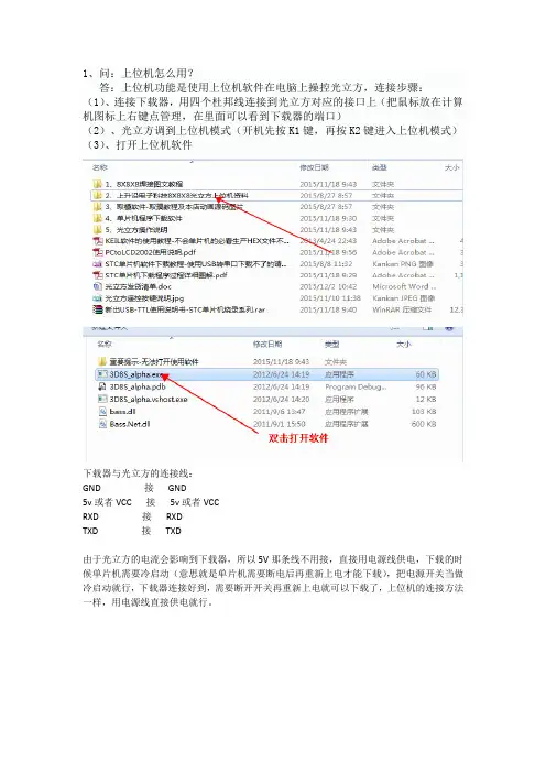
答:上位机功能是使用上位机软件在电脑上操控光立方,连接步骤:(1)、连接下载器,用四个杜邦线连接到光立方对应的接口上(把鼠标放在计算机图标上右键点管理,在里面可以看到下载器的端口)
(2)、光立方调到上位机模式(开机先按K1键,再按K2键进入上位机模式)(3)、打开上位机软件
下载器与光立方的连接线:
GND 接GND
5v或者VCC 接5v或者VCC
RXD 接RXD
TXD 接TXD
由于光立方的电流会影响到下载器,所以5V那条线不用接,直接用电源线供电,下载的时候单片机需要冷启动(意思就是单片机需要断电后再重新上电才能下载),把电源开关当做冷启动就行,下载器连接好到,需要断开开关再重新上电就可以下载了,上位机的连接方法一样,用电源线直接供电就行。

电脑控制器使用说明电脑控制器主要功能有监视压缩机运行状态,控制压缩机,保护压缩机,监控保养零件等。
电脑控制器是空压机的控制核心,对机组正常运行起关键作用,故请用户使用前详细阅读本控制器使用说明。
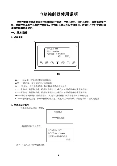
一、基本操作1、按键说明图1ON——起动键:按此键可起动电机运行OFF——停机键:按此键可停止电机运行M——设定键:修改完数据后,按此键确认数据存储输入❽——上移键:数据修改时,按此键上翻修改该数位;在菜单选择时作为选择键。
❾——下移键:数据修改时,按此键下翻修改该数位;在菜单选择时作为选择键。
❼——移位键/确认键:修改数据时,此键作为移位键;在菜单选择时作为确定键。
RT——返回键/复位键:在菜单操作时作为返回键返回上一级菜单;故障停机时,按此键复位。
2、状态显示与操作机组通电后显示如下界面:5秒后显示以下主界面:按“❾”进入以下菜单选择界面:a、运行参数查看按“❾”或“❽”移动黑色滚动条到“运行参数”菜单后,按确认键“❼”后弹出下一级菜单:再按“❼”弹出如为最后一级菜单,界面不会出现黑色滚动条,按返回键“RT”返回上级菜单或主界面。
如在某一界面停止操作,数秒钟后自动返回主界面。
用“❾”、“❽”移动键、确认键“❼”和返回键“RT”根据上述方法可完全观察到运行时间、本次运行时间、维护参数、历史故障、出厂日期、现场故障等运行参数并返回到上级菜单。
b、日历时间按“❾”或“❽”移动黑色滚动条到“日历”菜单后,按确认键“❼”后弹出在停机状态下可对日期、时间进行调整,操作方法为:按“❾”或“❽”移动黑色滚动条到需修改的参数项后按确定键“❼”后出现闪烁位,此时“❾”和“❽”键变为上翻和下翻键修改当前位,“❼”变为移位键移动修改位。
修改完毕后按“M”确认并保存,“❾”或“❽”变回移动黑色滚动条,“❼”变回返回键。
c、用户参数1)、参数修改方法══在运行状态和停机延时过程中不能修改用户参数和厂家参数══用前述运行参数查看的方法可查看和修改用户参数,如修改压力上限,操作方法如下:按“❾”或“❽”移动黑色滚动条到“用户参数”项后按确定键“❼”弹出再按确定键 “❼”弹出如不继续按确定键 “❼”即可查看用户参数。
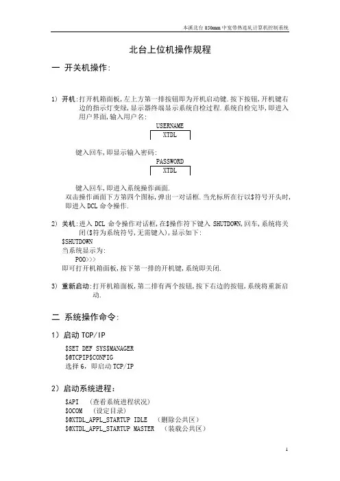
北台上位机操作规程一开关机操作:1) 开机:打开机箱面板,左上方第一排按钮即为开机启动键.按下按钮,开机键右边的指示灯变绿,显示器终端显示系统自检过程.系统自检完毕,即进入用户界面,输入用户名:键入回车,即显示输入密码:键入回车,即进入系统操作画面.双击操作画面下方第四个图标,弹出一对话框.当光标所在行以$符号开头时,即进入DCL命令操作.2) 关机:进入DCL命令操作对话框,在$操作符下键入SHUTDOWN,回车,系统将关闭($符为系统符号,无需键入),显示如下:$SHUTDOWN当系统显示为:POO>>>即可打开机箱面板,按下第一排的开机键,系统即关闭.3) 重新启动:打开机箱面板,第二排有两个按钮,按下右边的按钮,系统将重新启动.二系统操作命令:1)启动TCP/IP$SET DEF SYS$MANAGER$@TCPIP$CONFIG选择6,即启动TCP/IP2)启动系统进程:$API (查看系统进程状况)$OCOM (设定目录)$@XTDL_APPL_STARTUP IDLE (删除公共区)$@XTDL_APPL_STARTUP MASTER (装载公共区)3) 显示轧线跟踪状况:$SEEMILL显示整条轧线的检测器,区占有,CPDA等状况:上半部分:| 1 | | 2 | | 3 | | 4 | | 5 | | 6 | | 7 | | 8 | | 9 || 1 | | 0 | | 0 | | 0 | | 0 | | 0 | | 0 | | 0 | | 0 || CTB | | DTB | | R2E | | R2D | | ETB | | FM | | GTB | | CL1 | | CL2 || 0 | | 0 | | 0 | | 0 | | 0 | | 0 | | 0 | | 0 | | 0 || 9 | | 9 | | 9 | | 9 | | 9 | | 9 | | 5 | | 5 | | 8 |第一行:序列号第二行:区首检测器,1表示ON,0表示OFF第三行:区占有名称第四行: 区占有标志,1表示有钢,0表示无钢第五行:CPDA号下半部分:[--id1 --] [--id2 --] [--id3 --] [--id4 --]|11011 C11| |00011 H33| |00011 H43| |00100 FT7||00000 C14| |00000 H34| |00011 H44| |00000 H51||00000 C16| |00000 R2L| |00000 E2L| |00011 CT||00000 C17| |00011 RT2| |00000 F1L| |00000 H61||00001 LAS| |00000 H35| |00011 F2L| |00100 H62||00000 H21| |00011 H36| |00011 F3L| |00001 CL1||00011 S_L| |00000 H37| |00011 F4L| |00001 CL2||00000 EMP| |00000 FT0| |00011 F5L| |00001 UP1||00000 H31| |00100 H41| |00011 F6L| |00001 UP2||00100 H32| |00011 H42| |00000 F7L| |00011 EMP| (ID中:左边数字显示(从左到右):前两位表示检测器接通状况,1表示接通,0表示未接通;最后两位为历史记录;右边为检测器名称;)ID中:左第一位显示DPFTRUTH(mill state),左第二位显示TRKS(1,J),中间显示TRKS(2,J),第四位显示SCNFLG,第五位显示DPFOLD(millstate of last scanning)$SEEMILL1 (显示轧线检测器,负荷继电器,辊道正反转情况)4)板坯数据输入板坯原始数据及轧制规格数据,用PDI方式进行输入(PDI画面装在精轧数度主画面上)。

ProDriver使用简易说明目录一、P RO D RIVER使用概述 --------------------------------------------------------------------------------------------------------- -3-二、P RO D RIVER基本使用简介: ------------------------------------------------------------------------------------------------ -4-三、故障信息 ------------------------------------------------------------------------------------------------------------------------ -23-一、ProDriver使用概述ProDriver作为驱动器的参数设置与调试软件,主要为我们完成电机控制参数的设定,以及调试监控功能。
电机参数,通常我们都有现成的电机模板参数文件或者ProDriver中自带的电机参数库文件,完成参数DATA的Download工作。
对于一台新的驱动器,简单的电机运转测试过程:1、联机确认驱动器的型号正确2、选择正确的Motor型号。
(ProDriver、导入文件或自己根据参数设定)3、确认Power、编码器以及转速、报警等安全参数设定无误4、寻找编码器原点5、Autotuning自整定6、通过Ramp function generator运行Speed control 进行简单的电机动作测试7、回原点方式设置并运行测试(如果有使用需求的话)如果有其他的模块使用,可参见详细的ProDriver参数手册,进行相关设置。
使用提示:1、确认你点击了软件左下角的Connect按钮进行了联机。
2、注意驱动器的设定参数有保存save至EEPROM中。
目录电解循环水 (2)电解烟气 (2)空压机循环水 (3)加压泵站操作步骤 (6)江边泵站 (7)天然气调压站 (8)报警信息 (8)设备操作权限优先级别是就地操作具有最高权限,其次是上位机操作,设备运行——绿色,设备故障——黄色,设备停止——蓝色,设备操作方式有两种:就地、上位机。
启明星上位机系统操作画面由九个部分组成,它们分别是主画面、电解循环水、电解烟气、空压循环水、加压泵站、江边泵站、天然气调压站、报警、参数趋势;电解循环水1.电机运行画面2.模拟量参数趋势图电解循环水上位机操作方式设置分为系统手动和自动,控制模式分为上位机和设备现场就地;在进行设备操作前应第一确认设备是否处于远程控制,第二确认电机显示状态是否符合启动条件,第三确认画面右上角是否显示“中控模式”,第四确认上位机操作方式设置是系统手动还是系统自动;在上位机中控“手动”方式下,可以远程对一号电机、二号电机、冷却风机进行启、停操作,具体操作方法:用鼠标单击设备对应中文名称,例如“一号电机”,就会弹出一个小操作窗口,在这个窗口里设置了“启动”和“停止”按钮,发出命令之后松开鼠标小窗口会自动消失。
电解烟气1.袋滤器一系统A、B面画面;2.袋滤器二系统A、B面画面;3.袋滤器压差画面;4.排烟风机画面;5.模拟量趋势图;电解烟气排烟风机上位机操作方式设置只为排烟风机设置系统手动和系统自动停机方式,其中“手动”方式停机方式是根据生产运行的需要对风机进行远程发出停止命令,启动风机则需要到现场就地启动,在上位机中没有设置这个按钮;“自动”方式停机方式根据风机运行电流经过PLC延时2分钟之后再做出判断电流高信号是否有效,如果这个电流超出设定的范围就会立即停机;袋滤器一、二系统A、B面画面分别设置了袋滤器运行参数显示和对时间设置等功能;袋滤器压差画面主要设置24路压差信号进入PLC后,直接反映到上位机画面上,以便生产人员比较直观,便捷了解袋滤器压差情况,更方便判断滤袋是否破损。

上位机软件版本说明 u2.5版上位机分析软件版本说明: 1.在通信过程处理方面,重新改写了通信处理模块和通信错误处理模块,从而提高了通信时间及数据处理速度,在通信数据量为最大时(即采样点数为28650)的情况下,通信时间缩短为3.5分钟。
与2.0版软件相比提高了二到三倍。
并对通信错误事件增加了错误处理诊断机制,可提示通信的连接状况及出错故障信息。
2.在数据库数据处理方面,重新改写了数据库输入输出处理模式,在原2.0版的基础上,新增了另一种数据库存储处理方式,采用二种不同的处理机制对数据库数据输入输出过程进行管理,从而对数据库的操作更为快速和灵活。
3.在数据库构成方面,重编了新的数据库管理模式,将原先静态管理改写动态数据库管理,对数据库的管理更为方便,可以动态增加、删除数据库表,并在此基础上,增加了历史数据库功能,以便于日后的查询和分析钢丝绳损伤变化。
4.与原数据库相比,在数据库打开及保存时,增加了数据库压缩功能,可直接由程序内部对庞大的数据库进行压缩处理,从而使得数据库所占空间容量小的多,占用空间基本上为200多K到1M多之间。
从而可以保存大量的历史数据记录。
如果有2G容间的话,可保存几年的损伤数据。
5.放弃了2.0版软件中使用第三方控件来显示损伤曲线的方式,重新编写了损伤曲线显示代码,采用新的图形显示方式,从而对损伤曲线显示过程可自由进行控制。
在显示损伤曲线时,可显示全值曲线、正值曲线、负值曲线;X轴缩放比例和Y轴缩放比例要比原先选择范围更详细,可自由调整。
同时在调整上述任一选项时,损伤曲线动态跟随变化显示。
与原2.0版程序相比,显示曲线更快速。
6.损伤曲线显示时,新增加了鼠标动态跟随损伤曲线来显示损伤位置、损伤量值、损伤类型的指示。
不再采用2.0版软件中,损伤位置、损伤量值信息只能位于右上角固定位置显示的方式,同时修正了鼠标移动时对显示范围的控制功能。
不至于出现看不到的情形。
7.对损伤曲线的显示,专门增加了一个动态数据库功能,不影响原始损伤采样数据,并对损伤曲线数据进行了优化处理,一次只显示几百个数据,占用处理时间极小,从而可非常快速的进行曲线显示并消除了曲线显示时的闪动影响。

LEDPRORFKWHInstallation&OperatingInstruction s Dedicated PIR Light Controller c/w RF remote control for LEDPRO Floodlights Model: LEDPRORFKB – Black Model: LEDPRORFKWH – White Model: LEDPROFOB RF Remote Fob11. General InformationThese instructions should be read carefullyand retained for further reference and maintenance.2. Safety•Before installation or maintenance, ensure the mains supply to the PIR sensor is switched off and the circuit supply fuses are removed orthe circuit breaker turned off.•It is recommended that a qualified electrician is consulted or used for the installation of this PIR sensor and install in accordance with the current IEE wiring and Building Regulations.•Check that the total load on the circuit including when this PIR sensor is fitted does not exceed the rating of the circuit cable, fuse or circuit breaker.3. Technical Specifications PIR Light Controller•Operating Voltage: 230V AC 50Hz•This product is of Class I Construction and must be earthed.•Detection Angle: 180°2•Motion Detection Range:Up to 12m distance at a 2.5m mounting height •Maximum Switchable Load;140W LED Lighting1000W Halogen Lighting200W CFL Lighting500W Fluorescent tube w/o PF correction •Time ON Adjustment: 3 seconds – 18 minutes •Warm Up Period: Approximately 35 seconds •Dusk (LUX) Level Adjustment: 2 – 1000 Lux •Operating Temperature: -20°C to +40°C •Standby (W): <0.5W•Manual Override Mode:ON/OFF operation using RF Remote Fob (6 fobs max)•Sensor Head Adjustment:Pan angle = Left/right 90°, Tilt angle = Down 150°•RF Module: RX Receiver•RF Frequency: 433.92MHz•IP55 Rated suitable for restricted external applications •CE Compliant•Dimensions (H x W x D): 114 x 78 x 127mmRF Remote Fob•Battery: 3V (1x CR2032)•Battery Life:Approximately 24 months (@ 10x opt/day)•Class Rating: Class III3•Transmission and Receiving Distance:100m hand held (clear line of sight)10m when mounted inside a wall switch (recommended mounting height = 1.2m)•Total number of fobs usable per PIR: 6•Operating Temperature: -20°C to +40°C•RF Module: TX Transmitter•RF Frequency: 433.72MHz to 434.12MHz•IP44 Rated suitable for restricted external applications•CE Compliant•Dimensions (H x W x D): 60 x 38 x 15mm4. Pack contents•1x LEDPRORFKB-WH Dedicated PIR Light Controller c/w RF remote control for LEDPRO Floodlights•1x LEDPROFOB RF Remote Fob•1x Instruction Manual•1x 3V CR2032 Battery•1x Lens Sticker•2x Wire (for wall mounting a fob)5. Selecting a Location•The light controller has number of detection zones, at various vertical and horizontal angles as shown (see diagram A).4• A moving human body needs to cross/enter one of these zones to activate the light controller. The best all-round coverage is achieved with the unit mounted at the optimum height of 2.5 metres.•Careful positioning of the light controller will be required to ensure optimum performance (see diagram A detailing detection range and direction).•The light controller is more sensitive to movement ACROSS its field of vision than to movement directly TOWARDS (see diagram B). Therefore position the unit so that the light controller looks ACROSS the likely approach path.•Avoid positioning the light controller where there are any sources of heat in the detection area (extractor fans, tumble dryer exhausts etc.) including opposite any other light sources such as other security lights.•Reflective surfaces (i.e. pools of water or white painted walls) and overhanging branches may cause false activation under extreme conditions.56. Installation6.1Ensure the mains supply isswitched off and the circuitsupply fuses are removed orthe circuit breaker turned off.6.2An isolating switch should be installedto enable the power to be switched ON & OFF for maintenance purposes.•During extreme weather conditions the motion light controller may exhibit unusual behaviour. This does not indicate a fault with the lightcontroller. Once normal weather conditions return, the light controller will resume normal operation.66.3Remove the jumper plug from the floodlight.6.4Pass the 230V 50Hz mains supply and loadcables the holes provided on the PIR ensuring that a cable gland, grommet or sealingcompound is used to maintain the IP rating. 6.5Terminate the cables into the terminal blockensuring correct polarity is observed and that all bare conductors are sleeved (See section 7. Connection Diagram).6.6Ensure that all connections are secure.76.7Connect the 3 way PIR plug, by pushing theplug and socket inside the floodlight togetheruntil they lock. DO NOT FORCE. THE PLUG AND SOCKET WILL ONLY FIT TOGETHER ONE WAYAROUND (See Jumper Plug diagram).6.8Secure the PIR to the floodlight using the4 fixing screws.87. Connection Diagram•Connect the cables to the terminal block as follows;•Note: The Switch Live terminal is for additional standalone floodlights (see section 3. Technical Specifications for maximum switchable loads). Any floodlight connected to the L1 switch live terminal ‘Live Output’ will be controlled by the PIR98. Setting UpWalk Test Procedure (Test Mode)•The sensor will rotate from left to right, and will tilt downwards. Adjust the light controller to point in the required direction and angle down to limit forward range as required.•Set the two adjustment controls on the undersideof the unit to the following positions:TIME ADJUST – Fully anti-clockwiseDUSK/DAWN LEVEL ADJUST – Fully clockwise •Turn the power to the unit ON.10•The floodlight will illuminate for approximately35 seconds. This indicates the unit is wired correctly. The unit is in Test Mode when the light turns OFF.•If the detection area is too big for your requirements, try angling the PIR light controller head downwards. This will reduce the detection area should a smaller coverage be required. Setting Up for Automatic Operation(Auto Mode)•When walk tests are complete, the unit can be set into Auto Mode.•The TIME ADJUST setting controls how long the unit remains illuminated following activationand after all motion ceases.•The minimum time (fully anti-clockwise) is approx.3 seconds, whilst the maximum time (fully clockwise) is approximately 18 minutes.•Set the control to the desired setting between these limits.•The DUSK/DAWN LEVEL ADJUST control determines the level of darkness required for the unit to start operating. The DUSK adjustment knob is indicated by the ‘Moon’ and ‘Sun’ symbols).11•Set the light threshold to maximum (fully clockwise/ Sun end), then turn the control anti-clockwise about three quarters of the way round to the Moon end. This will give operation afterDUSK approximately.•For a more accurate setting of the DUSK/DAWN LEVEL ADJUST control turn it fully anti-clockwise (Moon end) and leave for at least 20 seconds for the unit to settle.•When the ambient light level reaches that required for DUSK, adjust the DUSK control a small amount clockwise pausing to try to get the unit to detect and turn the lights under control ON by movinga hand slowly backwards and forwards across the front of the detector lens for around 5 seconds.•Continue to turn the control small amounts ina clockwise direction, stopping after each adjustment to try to get the unit to detect as above.•Eventually detection will occur and the DUSK level is now set as required.12Battery•To access the battery holder,remove the back plate fromthe fob as shown inthe diagram.9. Masking the PIR Light Controller Lens•To reduce the PIR light controllers coverage,preventing detection in unwanted areas, mask the PIR light controllers lens using the lens sticker supplied.•The top section of the lens covers long range detection, the bottom covers short range. Similarly the left and right lens sections cover the left and right detection area respectively.•Mask the PIR Light controllers lens to suityour installation.13Pairing the RF Remote Fob(s) with the PIR Light ControllerNote: You must complete the Walk Test Procedure before you can pair the devices. The pairing of the fob(s) cannot be actioned with the PIR light controller set to Test Mode. Make sure the PIR light controller is functioning correctly and set for Automatic Operation (Auto Mode) before you continue.•is located on the bottom(do not press and hold forNote: once the lamp has flashed twice, the PIR sensor will no longer trigger the lamp with motion until the pairing sequence has been completed.•The lamp will turn ONOFF again, to indicateit has been registered.14Note: If you have more than one fob to pair (Up to 6 max) then press the fob buttons, one at a time, waiting for the lamp to turn ON for 3 seconds and back OFF again each time, between presses. You cannot pair a 7th fob. If attempted, the lamp will flash twice to indicate it has not been paired.•After the last fob press, wait for approximately30 seconds until the lamp flashes twice.This will indicate that your fob(s) have successfully been paired.Note: once the lamp has flashed twice, the PIR light controller will begin to trigger with motion once again.•Test your fob(s) by pressing the fob button once to turn the lamp ON, and once to turn the lamp OFF. If you are using more than fobs, you are ableto turn the lamp ON using one fob, and turnthe lamp OFF using another.15•Using 2 of the wires supplied,push them firmly into the 2 springclamp terminals. Check they areboth secure with a light tug.Erase all RF Remote Fobs from the PIR Light Controller•Press and hold the centre button, located on the bottom of the PIR light controller, for approximately 5 seconds. The lamp will flash 5 times. This indicates that un-pairing has been successful.Installing a RF Remote Fob into a Wall Switch •Remove the rubber caps fromthe bottom of the fob as shown.w/o 230V AC Potential16•Follow the wallswitch wiringimage forconnection.11. Troubleshooting Guide PROBLEM •Lamp stays ON all the time night and day.SOLUTION Check wiring connections. Wires to L and L’ terminals may be transposed.•Lamp stays ON all the time at night, or PIR keeps activating at random for no apparent reason The unit may be suffering from false activation. Cover the sensor lens completely with black PVC tape. This will prevent the sensor from ‘seeing’ anything. If the unit now switches off after the set time duration and does not re-activate, this indicated that the problem was caused by false activation. The problem may be solved by slightly adjusting the direction/angle of the sensor head (see previous section). If however, the unit continues to remain ON or to operate randomly then the unit is faulty and should be replaced.17•PIR sensorwill not operateat all.Check that the power is switched ON at thecircuit breaker/internal wall switch.Turn OFF the power to the unit and checkthe wiring connections as per the diagram(see 7. Connection Diagram).Ensure no connections are loose.Check the bulb (if it’s replaceable). If thebulb has failed, replace (do not hold thebulb directly with fingers, use a tissue orclean dry cloth).Where relevant, ensure the bulb is seatedcorrectly in the bulb holder.•The PIR sensorwill not operateat night.Refer to section 8. Setting Up for DUSKcontrol adjustment.•Unit activatesduring thedaytime.Refer to section 8. Setting Up for DUSKcontrol adjustment.You may not be allowing the unit time tocomplete its warm-up period. Stand well outof the detection range and wait (the warm-up period should never exceed 5 minutes).Occasionally, winds may activate the sensor.Sometimes passages between buildingsetc. can cause a “wind tunnel” effect.Ensure the unit is not positioned so as toallow detection of cars/people using publicthoroughfares adjacent to your property.Ensure that the unit is mounted securely,even the slightest movement can resultin a false detection.183 Year GuaranteeIn the unlikely event of this product becoming faulty due to defective material or manufacture within 3 years of the dateof purchase, please return it to your supplier in the first year with proof of purchase and it will be replaced free of charge. For the second and third years or any difficulty in the first year telephone the helpline on 020 8450 0515.Note: A proof of purchase is required in all cases. For all eligible replacements (where agreed by Timeguard) the customer is responsible for all shipping/postage charges outside of the UK. All shipping costs are to be paid in advance before a replacement is sent out.•PIR coverage ispoor/ sporadic.Unit may be poorly located. See Section5. Selecting a Location and re-locatethe unit.•Detection rangevaries from dayto day.PIR sensors are influenced by climaticconditions. The colder the ambienttemperature, the more effective the sensorwill be. You may need to make seasonaladjustments to the sensor head positionto ensure trouble-free operation all yearround.67.058.622 (Issue 2)Timeguard Limited. Victory Park, 400 Edgware Road, London NW2 6ND SalesOffice************or email csc @ For a product brochure please contact:Qualified Customer Support Coordinators will be online to assist in resolving your query.If you experience problems, do not immediately return the unit to the store. Telephone the Timeguard Customer Helpline:HELPLINE ***********or email helpline @ Zerofour – June 2018LEDPRORFKWH。

普罗名特® 多功能阀操 作 手 册P r o M i n e n t®目录1结构设计 (1)2功能描述 (1)3使用范围 (2)4安装 (3)5操作 (3)6技术参数和订货号 (4)1结构设计多功能阀通过弹簧负载的隔膜实现其每个功能。
阀的卸压机构具有保持压力恒定以及卸压的功能。
2功能描述功能- 敞口计量时,产生一个稳定的背压。
顺时针方向旋转黑色星状旋钮(1)可取消此项功能。
- 防止投加点产生负压时从药桶中抽出药液。
顺时针方向旋转黑色星状旋钮(1)可取消此项功能。
注意背压阀不能用作完全密封截止阀。
1 2如果不向投加点输送计量介质或泵的待机时间长,则必须在泵的吸入端另外安装截止阀。
- 启动泵时克服压力辅助引液,而不必松开排液管线。
旋动红色星状按钮(2)实现此项功能。
注意— 由于阀工作时,系统的药液可能通过旁路管线流出,故必须在投加点安装单向止回阀。
- 当相关系统处于待机状态(例如维修)时,用于给计量管线卸压。
- 用作溢流阀,防止由计量泵产生的不允许的超压。
通过旁路管线溢流,自动执行溢流功能。
3 使用范围指定用途用于在关闭截止阀时,防止因计量泵产生的不容许的超压。
必须连接旁路管线。
非指定用途不能用于防止除计量泵以外的其它原因产生的不容许的超压。
此阀不能用作截止阀。
如果压力系统没有安装注射阀,不能使用此阀。
如系统没有安装旁路溢流管线,不能使用此阀。
4安装安全注意事项投加点必须安装单向止回阀,因为阀工作时系统中的计量介质通过旁路可能会产生回流。
机械/液压安装多功能阀直接旋到泵的压力连接端上,阀可以360°任意转动。
使用连接用具或GF螺纹配件,将计量管线或软管固定在泵的出口端上。
出厂前,EPDM材质的O型圈已安装在泵出口的凹槽内。
对于不适用EPDM材质的情况,建议安装Viton B型的O型圈,该O型圈(棕色)同阀一起供货。
使用卡环和管接螺母紧固旁路管线,并引回药桶。
因为阀在接近于开启压力时会出现少量的溢流,故必须始终接通旁路管线。
1、主要技术参数1.1型号:研华IPC-6101.2MTBF≮60000小时2、开机前准备2.1 检查上位机机箱后部的CAN总线接口卡的连线是否正确。
2.2 检查语音报警系统的与上位机连线是否正确。
2.3 检查打印机是否连接正确。
2.4 检查UPS是否工作正常。
2.5 检查总线上各台YFC-99型槽控机的物理槽号是否设置正确,不得有重复现象。
3、开机过程3.1 打开液晶显示器。
3.2 打开工控机。
3.3 检查操作系统中各设备驱动程序是否安装正确。
3.4 如需语音报警,则打开语音报警系统。
3.5 如需打印报表,则打开打印机。
4. 运行中的具体要求4.1启动如下图4.1.1,双击桌面上接口机程序,即可启动上位机软件。
图4.1.14.2 日常监控4.2.1 主临控界面系统运行后,自动进入主监控界面,主监控界面可进行各槽槽电压,系列电流,各槽重要信息的监控,正常情况下,系统监控人员应主要监控此画面。
由上图可看出本窗口从上到下分为五个部分:(1)最上面是标题区;(2)接下来菜单条和工具条区;(3)再下来是主体信息显示区,主体信息显示区提供每台槽的槽号、实时电压(由于采用CANBUS总线来构造下位机系统,信息显示速度能达到2秒)及各种状态和故障信息;(4)再下来是重要提示信息区;(5)最下面是常用信息显示区。
注:把鼠标悬停在某槽槽号之上,就会在“重要提示信息状态栏”上边显示该槽控机的完整信息;鼠标左键点击某槽槽号,则进入该槽15分钟动态曲线画面。
鼠标停在某槽槽号上,单击鼠标右键,则进入槽控机模拟面板显示。
4.2.2 主显示窗口单击监控界面快捷按钮或点击“系统操作”菜单下的“监控界面”,快捷键“Ctrl+J”,可进入主显示窗口界面。
监控界面中,出现“效应”、“电压摆”、“槽压异常”等异常状况时,对应槽号的“工作电压”栏将以分别以“红”、“绿”、“黄”颜色标记。
“一工区”与“二工区”界面约每10秒钟自动切换一次;单击主监控界面上的大组分项,可进入相应的大组主监控画面。
ProTool组态软件的介绍与使用ProTool组态软件的使用对象:通过使用ProTool组态软件,可在组态计算机(PC或PU)的Windows操作系统中为以下操作单元创建过程可视化项目:1.文本显示(如TD 17)2.带基于文本显示的操作面板(如OP 3、OP 7、OP 17)3.带图形显示的操作面板(如OP 27、OP 37)4.触摸面板(如TP 27、TP 37)5.基于Windows的系统●Panel (TP 170A、TP 170B、OP 170B、TP 270、OP 270)●Mobile Panel (Mobile Panel 170)●Multi Panel (MP 270、MP 270B、MP 370)●OP 37/Pro●Panel PC (Panel PC 670、Panel PC 870、Panel PC IL、FI 25、FI 45)●PC6.C7单元(如C7-621/623/633/634/635OP/635TP)ProTool组态软件的版本级别:●ProTool/Pro 用于组态整个单元系列。
●ProTool 用于组态文本显示、文本和图形操作面板以及基于Windows的单元。
●ProTool/Lite 用于组态文本显示、基于文本的操作面板和基于Windows的单元TP170A、TP170B和OP170B。
ProTool组态软件的安装1.将安装光盘插入光盘驱动器。
数秒之后安装程序自动启动;2.单击“安装”;3.单击“ProTool”、“ProTool/Lite”或“ProTool/Pro”;4.按屏幕指示进行;5.按要求安装许可证。
注意:在Windows® NT、Windows® 2000和Windows® XP下进行安装要求有管理员权限。
安装后,组态软件必须由具有本地管理权限的用户启动一次,以使ProTool系统文件成功注册。
ProTool组态软件的使用步骤1.启动ProTool组态软件双击桌面上的ProTool组态软件图标。
上位机操作规程上位机操作规程1 范围本规程规定了西南管道公司上位机的操作。
本规程适用于西南管道公司Telvent OASYS上位机、Cegelec Viewstar上位机、Honeywell PKS上位机、Schneider InTouch上位机、FactoryTalk上位机、Epipeview上位机的操作。
2 规范性引用文件下列文件对于本文件的应用是必不可少的。
凡是注日期的引用文件,仅所注日期的版本适用于本文件。
凡是不注日期的引用文件,其最新版本(包括所有的修改单)适用于本文件。
Q/SY 201 油气管道监控与数据采集系统通用技术规范Q/SY 1596 油气管道监控与数据采集系统运行维护规程XNGD/CX.shch.05-2019-1/D 仪表自动化专业管理程序OASYS系统软件操作维护规程钦州-南宁成品油输油管线SCADA系统操作及维护手册Factory Talk View Studio 系统操作规程安宁首站操作手册与用户指南Epipeview4.0软件用户手册3 术语和定义下列术语和定义适用于本文件。
3.1 SCADASupervisory Control And Data Acquisition系统,全名为监视控制与数据采集系统。
3.2 OASYSTelvent 公司的上位机工程软件。
PKSProcess Knowledge System,Honeywell公司的上位机工程软件。
3.3 ViewstarCegelec公司的上位机工程软件。
3.4 InTouchSchneider公司的上位机工程软件。
3.5 FactoryTalkAB公司的上位机工程软件。
3.6 Epipeview中油龙慧自动化工程有限公司的上位机工程软件。
3.7 ESDEmergency Shut Down紧急关断系统,是故障安全型控制系统。
3.8 HMIHuman Machine Interface,人机界面。
3.9 上位机上位机也叫操作员工作站,人机界面提供给操作员一个监视过程参数和控制生产过程的操作显示窗口。
神宁炭基活性炭厂集中控制系统操作手册平顶山中选自控系统有限公司神宁炭基活性炭厂集中控制系统操作手册一、集控系统的起动与退出起动:计算机开机后,点击桌面上的“神宁炭基活性炭集中控制系统”图标(下图)来启动集中控制系统。
集控系统起动后的画面如下图示,上部是标题栏,中间是主画面显示区,下部是页面导航栏,点击导航栏按钮可以切换显示不同的画面:退出:点击集控系统画面右下角的退出图标即可退出集控系统。
二、设备的起停操作参与集控的设备有两种工作方式:集中、就地,这两种工作方式由现场控制箱上的“集中/就地”选择旋扭来选择。
集中工作方式:在“集中”工作方式下,设备的起停由PLC控制,在人机界面上,相应处于“集控”状态的设备,其设备号显示为黄色(ZF201),可通过在人机界面上点击设备号来控制设备的起停,此时,现场起车按钮无法控制起车,但停车按钮可以停车;具体操作方法:用鼠标点击需要起停设备的设备号,系统会弹出设备起停控制对话框:1、对于普通单向动作的设备,其对话框如下:根据设备的当前状态,系统会让操作员确认是否要对设备进行起停操作,操作员确认后,系统将对设备发出相应的起停控制指令。
2、对于正反转设备,其对话框如下:操作员通过点击相应的“正转”、“反转”、“停车”按钮来控制设备的“正转”、“反转”和“停车”。
“联锁”和“解锁”当设备处于“集中”工作方式时,有“联锁”和“解锁”两种工作状态,当设备处于“联锁”状态时,它的起停与其它设备之间存在联锁关系,其起停受其它设备当前开停状态影响,在人机界面上以图标:来标识;当设备处于“解锁”状态时,它的起停不受其它设备状态的影响,可以自由起停,在人机界面上以图标:来标识。
设备的“联锁/解锁”状态可通过点击设备号旁边的“联锁/解锁”图标(/)进行切换。
就地工作方式在“就地”工作方式下,设备的起停由硬接线控制,在人机界面上,相应的设备号显示为灰色(ZF201),只能通过现场控制按钮来控制设备的起停。
鼎利P i o n e e r操作手册(总4页)-CAL-FENGHAI.-(YICAI)-Company One1-CAL-本页仅作为文档封面,使用请直接删除鼎利Pioneer操作手册一、设备要求: .............................................. 错误!未指定书签。
二、Pioneer软件的安装....................................... 错误!未指定书签。
三、大唐手机驱动安装:....................................... 错误!未指定书签。
四、GPS和MOS盒安装......................................... 错误!未指定书签。
五、话音和FTP的DT设置 ..................................... 错误!未指定书签。
5.1、配置工程:......................................... 错误!未指定书签。
5.2、开始测试:......................................... 错误!未指定书签。
六、注意事项: .............................................. 错误!未指定书签。
七、鼎利技术支持联系人:..................................... 错误!未指定书签。
一、设备要求:大唐8120手机3套MOS一套贝尔金一转四一套USB GPS一部软件狗一个二、Pioneer软件的安装双击PioneerSetup3.6.1.33.exe(软件版本以实际为准),按下一步操作:点击“下一步”:选择我同意,然后点击“下一步”:点击“下一步”:安装结束后,会自动弹出如下提示,要求安装两个软件“MSXML 4.0 SP2”和“WinPcap4.0.2”,这两个软件是每次安装Pilot Pioneer软件都要重新安装的,依次点击下一步安装,直至最后点击“Finish”完成Pioneer的安装。
山东天阳碳素有限公司焙烧温控系统计算机集中监控操作手册贵阳振兴铝镁科技产业发展有限公司贵阳市金阳新区金朱路2号550081电话0851-*******贵州·贵阳2010年9月目录一、概述.......................................................................................................................................................... - 4 -1.1 系统基本情况................................................................................................................................................ - 4 -1.2 温控系统介绍................................................................................................................................................ - 4 -1.3 温控系统工作说明 ...................................................................................................................................... - 5 -1.4 名词解释 ......................................................................................................................................................... - 6 -二、操作说明 .............................................................................................................................................. - 7 -A.网络拓扑图 ................................................................................................................................................... - 8 -屏幕截图................................................................................................................................................................ - 31 -班级选择................................................................................................................................................................ - 31 -曲线修改................................................................................................................................................................ - 31 -历史数据查询...................................................................................................................................................... - 31 -查找历史报表...................................................................................................................................................... - 31 - 使能或打印........................................................................................................................................................... - 31 -B. 主画面.......................................................................................................................................................... - 31 -计算器 .................................................................................................................................................................... - 31 -系统登录................................................................................................................................................................ - 31 -系统交换................................................................................................................................................................ - 31 -C.系统监控1................................................................................................................................................... - 37 -曲线操作................................................................................................................................................................ - 31 -鼓风架显示画面 ................................................................................................................................................. - 40 -排烟架显示画面 ................................................................................................................................................. - 41 -D.系统监控2................................................................................................................................................... - 42 -E.报警画面 ....................................................................................................................................................... - 44 -报警属性................................................................................................................................................................ - 41 -F.历史趋势画面............................................................................................................................................. - 46 -燃烧架历史数据查询........................................................................................................................................ - 50 -排烟架历史数据查询........................................................................................................................................ - 50 -按炉室数据历史查询........................................................................................................................................ - 50 -G.综合数据一览 ............................................................................................................................................ - 50 -三、工控机使用和维护................................................................................................................... - 53 -一、概述1.1 系统基本情况:山东天阳碳素有限公司焙烧温控系统焙烧炉42室敞开式焙烧炉,每个炉室分别有9个火道,8个料箱,生产流程为8室运转。