压力阀PS10-30中文.pdf
- 格式:pdf
- 大小:998.55 KB
- 文档页数:2

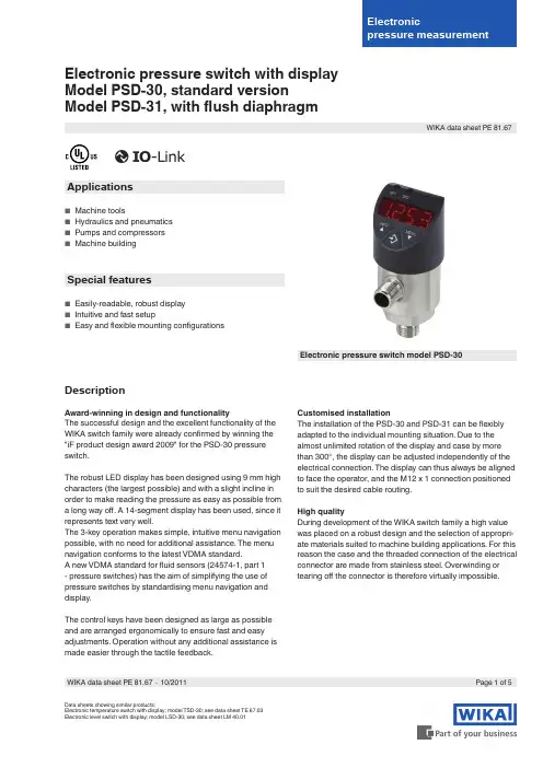
Electronic pressure switch with displayModel PSD-30, standard versionModel PSD-31, with flush diaphragmApplications■■Machine■tools■■Hydraulics■and■pneumatics■■Pumps■and■compressors■■Machine■buildingSpecial features■■Easily-readable,■robust■display■■Intuitive■and■fast■setup■■Easy■and■flexible■mounting■configurationsElectronic pressure switch model PSD-30 DescriptionAward-winning in design and functionalityThe■successful■design■and■the■excellent■functionality■of■the■WIKA■switch■family■were■already■confirmed■by■winning■the■"iF■product■design■award■2009"■for■the■PSD-30■pressure■switch.The■robust■LED■display■has■been■designed■using■9■mm■high■characters■(the■largest■possible)■and■with■a■slight■incline■in■order■to■make■reading■the■pressure■as■easy■as■possible■from■a■long■way■off.■A■14-segment■display■has■been■used,■since■it■represents■text■very■well.The■3-key■operation■makes■simple,■intuitive■menu■navigation■possible,■with■no■need■for■additional■assistance.■The■menu■navigation■conforms■to■the■latest■VDMA■standard.A■new■VDMA■standard■for■fluid■sensors■(24574-1,■part■1■-■pressure■switches)■has■the■aim■of■simplifying■the■use■of■pressure■switches■by■standardising■menu■navigation■and■display.■The■control■keys■have■been■designed■as■large■as■possible■and■are■arranged■ergonomically■to■ensure■fast■and■easy■adjustments.■Operation■without■any■additional■assistance■is■made■easier■through■the■tactile■feedback.Customised installationThe■installation■of■the■PSD-30■and■PSD-31■can■be■flexibly■adapted■to■the■individual■mounting■situation.■Due■to■the■almost■unlimited■rotation■of■the■display■and■case■by■more■than■300°,■the■display■can■be■adjusted■independently■of■the■electrical■connection.■The■display■can■thus■always■be■aligned■to■face■the■operator,■and■the■M12■x■1■connection■positioned■to■suit■the■desired■cable■routing.High qualityDuring■development■of■the■WIKA■switch■family■a■high■value■was■placed■on■a■robust■design■and■the■selection■of■appropri-ate■materials■suited■to■machine■building■applications.■For■this■reason■the■case■and■the■threaded■connection■of■the■electrical■connector■are■made■from■stainless■steel.■Overwinding■or■tearing■off■the■connector■is■therefore■virtually■impossible.Data■sheets■showing■similar■products:Electronic■temperature■switch■with■display;■model■TSD-30;■see■data■sheet■TE■67.03 Electronic■level■switch■with■display;■model■LSD-30;■see■data■sheet■LM■40.01Page■1■of■5WIKA■data■sheet■PE■81.67■∙■10/2011WIKA■data■sheet■PE■81.67Measuring rangesAbsolute pressurebar0■...■1■1)0■...■1.6■1)0■...■2.50■...■40■...■60■...■100■...■160■...■25 psi0■...■15■1)0■...■25■1)0■...■30■1)0■...■500■...■1000■...■1600■...■2000■...■300 Vacuum and +/- measuring rangebar-1■...■0■1)-1■...■0.6■1)-1■...■1.5-1■...■3-1■...■5-1■...■9-1■...■15-1■...■24 psi-14.5■...■0-14.5■...■15-14.5■...■30-14.5■...■50-14.5■...■100-14.5■...■160-14.5■...■200-14.5■...■300 1)■Not■available■for■PSD-31.Overpressure limit2■timesDisplay14-segment■LED,■red,■4-digit,■9■mm■character■size Display■can■be■turned■electronically■through■180°Update■(adjustable):■100,■200,■500,■1000■msOutput signalsAlternatively■also■available■with■an■NPN■instead■of■a■PNP■switching■output.With■the■IO-Link■option,■switching■output■1■is■always■PNP.Zero offset adjustmentmaximum■3■%■of■spanAnalogue signalCurrent■output■load:≤■500■ΩVoltage■output■load:>■10■kΩSettling■time:3■msSwitching outputSwitch■point■1■and■2■are■individually■adjustable Normally-open■and■normally-closed■function:freely■adjustable Window■and■hysteresis■function:freely■adjustable Switching■current■■without■IO-Link:maximum■250■mA■■with■IO-Link:maximum■100■mASwitching■voltage:Power■supply■-■1■VSettling■time:≤■10■ms Voltage supplyPower supplyDC■15■...■35■VThe■power■supply■for■the■pressure■transmitter■must■be■made■via■an■energy-limited■electrical■circuit■in■accordance■with■section■9.3■of■UL/EN/IEC■61010-1,■or■an■LPS■to■UL/EN/IEC■60950-1,■or■class■2■in■accordance■with■UL1310/UL1585■(NEC■or■CEC).■The■power■supply■must■be■suitable■for■operation■above■2,000■m■should■the■pressure■transmitter■be■used■at■this■altitude.Current consumptionmaximum■100■mAT otal current consumption■■without■IO-Link:max.■600■mA■including■switching■current ■■with■IO-Link:max.■500■mA■including■switching■currentAccuracyAnalogue signal≤■±■1.0■%■of■spanIncluding■non-linearity,■hysteresis,■zero-point■and■full■scale■deviations■(corresponds■to■measured■error■per■IEC■61298-2).■Calibrated■in■vertical■mounting■position■with■process■connection■facing■downwards.Non-linearity:≤■±■0.5■%■of■span■(BFSL,■IEC■61298-2) Long-term■drift:≤■±■0.2■%■of■span■(IEC■61298-2) Switching output≤■±■0.5■%■of■spanDisplay≤■±■1.0■%■of■span■±■1■digitT emperature error in rated temperature range■■typical:≤■±■1.0■%■of■span■■maximum:≤■±■2.5■%■of■spanT emperature coefficients in rated temperature range Mean■TC■zero■point:≤■±■0,2■%■of■span■/■10■K■(typical) Mean■TC■span:≤■±■0,1■%■of■span■/■10■K■(typical)WIKA■data■sheet■PE■81.67■∙■10/2011Page■2■of■5Reference conditionsT emperature:15■...■25■°CAtmospheric■pressure:950■...■1050■mbar Humidity:45■...■75■%■relativeNominal■position:Process■connection■lower■mount Power■supply:DC■24■VLoad:see■output■signalsOperating conditionsT emperatures and humidity Medium■temperature:-20■...■+85■°C Ambient■temperature:-20■...■+80■°C Storage■temperature:-20■...■+80■°C Rated■temperature■range:0■...■80■°C Permissible■humidity:45■...■75■%■relative MechanicsMounting■position:as■requiredVibration■resistance:10■g■(IEC■60068-2-27,■under■resonance)Shock■resistance:50■g■(IEC■60068-2-6,■mechanical)Service■life:10■million■load■cyclesIngress protection IP■65■and■IP■67■The■stated■ingress■protection■(per■IEC■60529)■only■applies■when■plugged■in■using■mating■connectors■that■have■the■appropriate■ingress■protection.Electrical connectionsConnections■■Circular■connector■M■12■x■1,■4-pin ■■Circular■connector■M12■x■1,■5-pin■1)1)■Only■for■version■with■two■switching■outputs■and■analogue■signalElectrical safetyShort-circuit■resistance:S+■/■SP1■/■SP2■vs.■U-Reverse■polarity■protection:U+■vs.■U-Insulation■voltage:DC■500■V Overvoltage■protection:DC■40■VProcess connectionsModel PSD-30DIN 3852-EG■1/4■A G■1/2■AEN 837G■1/4■BG■1/4■female G■1/2■BANSI / ASME B1.20.11/4■NPT1/2■NPTISO 7R■1/4KS PT■1/4-G■1/4■female■(Ermeto■compatible)Other■connections■on■request.SealingsDIN 3852-EStandard withoutOptionNBR,■FPM■/■FKMLegend:U +Positive■supply■voltage U -Negative■supply■voltage SP1■Switching■output■1SP2Switching■output■2S +Analogue■outputPage■3■of■5WIKA■data■sheet■PE■81.67■∙■10/2011Assignment U-S+SP1 24Circular■connector■M■12■x■1,■5-pinAssignment U- S+SP1 54MaterialsWetted partsProcess■connection:Stainless■steel■316L Pressure■sensor■■≤■10■bar:Stainless■steel■316L ■■>■10■bar:Stainless■steel■13-8■PH Non-wetted parts Case:Stainless■steel■304Keyboard TPE-E Display■window:PC Display■head:PC+ABS-BlendDimensions in mmApprovals, directives and certificatesStandard without OptioncULusCE conformity■■Pressure■equipment■directive■97/23/EC■■EMC■directive■2004/108/EC,■EN■61326■emission■(group■1,■class■B)■and■immunity■(industrial■application)RoHS conformity Y esWIKA Alexander Wiegand SE & Co. KG Alexander-Wiegand-Straße■3063911■Klingenberg/Germany T el.■(+49)■9372/132-0Fax■(+49)■9372/132-406E-mail■info@wika.de www.wika.deOrdering informationModel■/■Measuring■range■/■Output■signal■/■Process■connection■/■ApprovalsPage■5■of■5WIKA■data■sheet■PE■81.67■∙■10/201110/2011■G B©■2011■WIKA■Alexander■Wiegand■SE■&■Co.■KG,■all■rights■reserved.■The■specifications■given■in■this■document■represent■the■state■of■engineering■at■the■time■of■publishing.We■reserve■the■right■to■make■modifications■to■the■specifications■and■materials.。
SELECTION, INSTALLATION, OPERATION AND TROUBLESHOOTING GUIDEPRESSURE SUSTAININGNORMALLY OPEN (PSNO) VALVESVALVESIRON PSNO VALVEPVC PSNO VALVE2 ▪ PRESSURE SUSTAINING NORMALLY OPEN (PSNO) VALVESINTRODUCTION (4)Learn why a PSNO Valve will maximize flush cycleefficiency resulting in reduced maintenance, filter down-time and water use.SELECTION AND ORDERING (6)Includes guidelines for selecting the proper PSNO Valvealong with an ordering example and easy to understandordering charts.HEADLOSS CHARTS (8)Technical information for all sizes of PVC and Iron PSNOValves.COMPONENTS (9)A comprehensive listing of all the components in a PSNOValve along with illustrations, charts and model numbers.INSTALLATION AND MAINTENANCE (12)A review of installation, settings and adjustmentguidelines along with maintenance and winterizing tipsand information.3” AND 4” IRON OR PVC VALVES (13)6” PVC VALVES (15)6” IRON AND LARGER VALVES (17)Exploded drawings with components, descriptions,quantities and ordering information along with basictroubleshooting problems and solutions.PRESSURE SUSTAINING NORMALLY OPEN (PSNO) VALVES ▪ 34 ▪ PRESSURE SUSTAINING NORMALLY OPEN (PSNO) VALVESThe Netafim USA Pressure Sustaining Normally Open (PSNO) Valve is the universal solution for all types of filters. A PSNO Valve ensures that the filter will initiate a backflush cycle with the required pressure for proper cleaning. This is accomplished by maintaining the correct pressure upstream of the valve (downstream of the filter). After the backflush cycle, the filter element(s) will be thoroughly cleaned.With a PSNO Valve, Filters Flush More Efficiently Resulting in: • Less Maintenance • Less Downtime• Less Water and Energy UsedSince the filters flush less frequently and more efficiently, a PSNO Valve is ideal for all types of filters - media or disc. There is no need for a larger pump, saving capitaland operating expenses, to achieve the correct pressure during backflush.PSNO VALVES MAXIMIZE FLUSH CYCLE EFFICIENCYFOR ALL FILTERSPSNO VALVE FEATURESAccurate Stable Control of Upstream Pressure• Changes in flow do not affect the upstream pressure in the valve since the PSNO Valve pilot regulates this pressure Quick Reaction Time of PSNO Valve• Slightly before the filter starts flushing, the PSNO Valve goes into sustaining modefor quick reaction Manual Override on Solenoid for Easy Adjustments• Solenoid settings can be adjusted by simply turning a knob Hydraulic Valve with Direct Sealing Diaphragm • No stem, shaft or bearing within the water passage • Longer life with less maintenance Easy Installation and Low Maintenance• Netafim valves are the most reliable in the industry, resulting in less maintenance • They are easy to install and operatePSNO VALVE OPERATIONA PSNO Valve is always installed downstream of the filter. During standard operation, filtration mode, the PSNO Valve is fully open and flow or pressure to the field is not restricted. The solenoid is not energized at this time (See Figure 1).During the flushing mode, the solenoid is energized and the PSNO Valve partially closes in order to provide the desired pressure to the filter for proper flushing. This is referred to as the sustaining mode. During the sustaining mode, the valve maintains a “set” upstream pressure regardless of flow rate or pressure variations (See Figure 2).At the end of the flush cycle, the solenoid isde-energized and the PSNO Valve will fully open again.Figure 1: PSNO Valve Filtration Mode - valve is fully open and upstream pressure is 30 psi.Figure 2: PSNO Valve Flushing Mode - valve partiallycloses and upstream pressure raises to 40 psi (or any other adjustable set point).Flow Direction PSNO Iron Valve located downstream of a disc filter.NormallyClosedSolenoid3-WayManualSelector(Iron or PVC)4” PSNO PVC ValveControlTubingFingerFilterPRESSURE SUSTAINING NORMALLY OPEN (PSNO) VALVES ▪ 56 ▪ PRESSURE SUSTAINING NORMALLY OPEN (PSNO) VALVESSELECTION GUIDELINESWhen selecting a PSNO Valve, the following recommended flow ranges should be considered to ensure proper sizing and performance.It is recommended not to oversize the PSNO Valve. In relation to the specific flow (GPM), an oversized valve will require the diaphragm to be almost closed in the sustaining mode which can create high velocity, unstable regulation and potential cavitation.MAXIMUMORDERING EXAMPLEPipeline: 6”Required Flow Rate: 500 GPMWith a flow rate higher than 400 GPM, but lower than 600 GPM, a 4” valve is recommended. In this example, even though the pipeline is 6”, a 6” valve is not recommended.Choose the required voltage, Item and Model Numbers from the Ordering Information Charts on the next page.PRESSURE SUSTAINING NORMALLY OPEN (PSNO) VALVES ▪7PVC MATERIAL with SLIP CONNECTION3” PVC also available with threaded connection.IRON MATERIAL with FLANGED CONNECTIONNote: All PSNO Valves are also available with 12VDC and 12VDCL solenoids. Call Netafim USA Customer Service for item and model numbers. For pricing information, refer to the Agriculture Division Price List.8 ▪ PRESSURE SUSTAINING NORMALLY OPEN (PSNO) VALVESH E A D L O S S (p s i )FLOW (GPM)13247658925020035045055070012509001,75010HEADLOSS CHART - PVC VALVESH E A D L O S S (p s i )FLOW (GPM)1324765893005002007009001,5002,5004,0005,0007,00010HEADLOSS CHART - IRON VALVESPRESSURE SUSTAINING NORMALLY OPEN (PSNO) VALVE COMPONENTSA Pressure Sustaining Normally Open (PSNO) Valve ships pre-assembled by Netafim USA following strict quality standards. The PSNO Valve consists of a Basic Valve, a Normally Closed Solenoid, a Pressure Sustaining Pilot, andan Accelerator Relay (if the valve is 6” and larger).1. Basic Valve 3. PressureSustaining Pilot2. NormallyClosed Solenoid4. AcceleratorRelayPSNO Valve+++=1. BASIC VALVEThe basic valve consists of four simple parts - body, spring,diaphragm and bonnet - making it the simplest valve to operateand maintain. Installation is quick and easy with its unique inlinedesign which also creates low losses at high flow rates.• Available with two body material options - PVC or Iron• Stainless steel internal spring provides strength and long-life• Flexible reinforced direct sealing rubber diaphragm requires nobearings, guides or internal seals• Cover and body constructed of UV and corrosion resistantmaterialsBasic Valve - PVCBasic Valve - IronPRESSURE SUSTAINING NORMALLY OPEN (PSNO) VALVES ▪ 910 ▪ PRESSURE SUSTAINING NORMALLY OPEN (PSNO) VALVES1. BASIC VALVE, (con’t.)a. DiaphragmPVC and Iron valves are standard with a direct sealing natural rubber diaphragm. All Iron PSNO Valves use a high pressure diaphragm with a standard range of 10 - 230 psi. All PVC PSNO Valves use a low pressure diaphragm with a range of 2 - 60 psi.b. Hydraulic Control Tubing and FittingsHydraulic control tubing is used for various connections on the valve and the tubing size is different based on the valve size and material. Fittings are available in either Plastic or Prestolock Brass based on the valve size and material.*12mm tubing connects the Accelerator Relay of the PSNO Valve to the command filteron the Galaxy Automatic Disc-Kleen Filter.High Pressure DiaphragmHydraulic Control TubingPlastic FittingsPrestolock Brass Fittings2. SOLENOIDA solenoid valve receives an electric command from a controller and converts it into a hydraulic command to the main valve. This enables the opening and closing of the valve by allowing the passage of water into or fromthe control chamber of the main valve.Always use a Normally Closed (NC) Solenoid on all PSNO Valves. Standard solenoid is 24VAC NC. Choose from the following solenoids based on the available power source.All solenoids have a manual override feature. Turning the knob 90 degrees to the left or right will activate the solenoid and place the valve in Sustaining Mode. Latching solenoids have a three position lever for manualoverride. Turning the lever to the right or “O” position activates the solenoid and places the valve in Sustaining Mode. Left or “C” position turns the valve off. For automatic mode, the lever should be placed in the center(locked) position.SOLENOID ORDERING 24VAC Solenoid 12VDC Solenoid 12VDCL SolenoidPRESSURE SUSTAINING NORMALLY OPEN (PSNO) VALVES ▪ 113. PILOTA pilot is a mini-valve which ensures accuracy of the regulated pressure for hydraulic control valves. In PSNO valves, when the line pressure is lower than the pilot’s spring setting (the set point), the pilot permits the passage of water into the chamber of the main valve, partially closing the valve. PSNO Valves are standard with a Green Pilot Spring and a recommended set point of 45 psi.Pilot setting recommendations:• Automatic Disc-Kleen Filters Set the pilot to 40 - 45 psi • Sand Media Filters ................Set the pilot to 30 - 35 psi • Automatic Screen Filters .....Set the pilot to 30 - 35 psiPlastic PilotBronze Pilot4. ACCELERATOR RELAYAn Accelerator Relay is designed with large flow passages to allow faster reaction time of the main PSNO valve. As soon as the solenoid is energized, the relay allows larger amounts of water to flow into the main valve chamber, partially closing the valve. It is a standard component on all 6” and larger valves.ACCELERATOR RELAY Accelerator Relay12 ▪ PRESSURE SUSTAINING NORMALLY OPEN (PSNO) VALVESSETTINGS AND ADJUSTMENT GUIDELINESThe 3-Way selector must be in the A-position. The O-port is used to manually open the valve and the C-port to manually close the valve. A neutral position, not facing any of the ports, locks the water in the bonnet (used in case the pilot malfunctions).INSTALLATION GUIDELINES1. Install the valve downstream of the filter station.2. The arrow on the bonnet should match the flow direction.3. Verify that a finger filter was installed at the upstream pressure port of the valve.4. The valve can be installed in any position. When installing a 6” PVC Valve or a 12” Iron Valve, install the bonnets side by side, not one up and one down. This will allow for easier maintenance.5. For all threaded valves – use five layers of Teflon tape for proper installation.6. For all PVC slip valves – use primer and a heavy duty solvent.7. For all flanged valves – bolts should be tightened in a diagonal sequence.8. For 6” and larger iron valves, the needle valve connects to the 2” command filter on the Galaxy or main filterwith the supplied 12mm tubing. The tee fitting on the command filter will have an open end for attachment to the 12mm tubing from the needle valve.9. Connect the solenoid with the supplied 8mm tubing to the closest solenoid on the filter station by replacing theelbow fitting on the solenoid with a “T” connector.10. Wire the solenoid of the valve to the “M” (master valve) connector on the backflush controller.• For 6” Iron flanged valves and larger:- Open ball valves at the upstream and downstream ports of the valves - Close needle valve and then open it 3 full turns • Start the pump.• Make sure the lines are full and the designed pressure is reached.• Open the main valve manually and perform a backflush cycle with the controller.• The valve remains closed or opens slightly while the upstream pressure maintains a high level.• Loosen the bolt on the pilot until the upstream pressure reaches the minimum required level to backflush the filter.• Wait until the pressure stabilizes, make final adjustments and tighten the lock nut on the pilot.• If the manual override screw on the solenoid was used to manually open the valve in the previous step, turn it to the original position (automatic arrow facing base of the solenoid).• Initiate another backflush cycle from the backflush controller and make sure the valve reaches the set pressure before backflush. Measure the pressure with a pressure gauge. Adjust pre-dwell time in the controller if set pressure is not achieved before backflush.• If pressure is lower than the required set point, tighten the bolt on the pilot; every turn is approximately equivalent to 10 psi. Open the bolt if pressure is higher than set point.MAINTENANCE1. Keep the valve clear from weeds and dirt.2. Turn the handle of the 3-way selector periodically to prevent sticking.3. Verify the upstream pressure periodically, using a quality liquid filled gauge.WINTERIZINGDrain the valve by disconnecting the tubing from the access ports of the valve and at any location where water can be trapped.3” and 4” IRON/PVC VALVE COMPONENTSPRESSURE SUSTAINING NORMALLY OPEN (PSNO) VALVES ▪ 1314 ▪ PRESSURE SUSTAINING NORMALLY OPEN (PSNO) VALVESPRESSURE SUSTAINING NORMALLY OPEN (PSNO) VALVES ▪ 156” PVC VALVE COMPONENTSNotes:• 8mm tubing from the solenoid and 12mm tubing from the accelerator relay, attach to the 2” command filter of the main filter.• Solenoid ports may be labeled either P and A or 2 and 1.16 ▪ PRESSURE SUSTAINING NORMALLY OPEN (PSNO) VALVESPRESSURE SUSTAINING NORMALLY OPEN (PSNO) VALVES ▪ 176” IRON AND LARGER VALVE COMPONENTSNotes:• Solenoid ports may be labeled either P and A or 2 and 1.• 8mm tubing from the solenoid attaches upstream of the valve.• of the main filter.18 ▪ PRESSURE SUSTAINING NORMALLY OPEN (PSNO) VALVESPRESSURE SUSTAINING NORMALLY OPEN (PSNO) VALVES ▪ 19NETAFIM USA5470 E. Home Ave.Fresno, CA 93727CS 888 638 2346F 800 695 4753A080 03/12。
1. ISO 国际标准化组织EN 欧洲标准JIS 日本工业标准ANS 美国国家标准ANSI 美国标准协会SAE 美国动力机械工程师协会2. 将机械能转换为液体压力能:动力装置(泵或空压机)将液体压力能转换为机械能:执行装置液压执行元件有两种形式:实现直线往复运动的称为液压缸,实现旋转运动的称为液压马达。
3. 运动粘度的法定计量单位为m2 / s 。
以前沿用的单位St(斯)cSt(里斯)1m2 / s=104 St =106 cSt4. 按照ISO规定,采用40℃时油液的运动粘度(m2/ s)的某一中心值作为油液粘度牌号,共分为10、15、22、32、46、68、100、150等8个粘度等级。
5. 液压泵的排量是指泵每转一转,所输出的液体体积,用V表示。
其值是密封容积几何尺寸变化量。
排量可调的液压泵成为变量泵,不可调的称为定量泵。
流量是指液压泵在单位时间内输出液体的体积。
包括理论流量、实际流量和额定流量。
理论流量是根据泵密封容积几何尺寸计算而得的流量。
用q t表示。
实际流量是指泵工作时出口实际输出的流量。
用q表示,它与泄漏有关。
额定流量是指泵在正常工作条件下,按实验标准所必需保证的流量。
用q n表示。
实际流量和额定流量均小于理论流量。
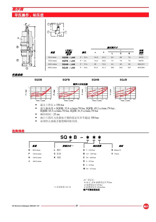
q=nV6.曲线箭头表示回转运动;斜线箭头表示可变操纵或调节措施。
7.压力的旧单位是bar(巴),1bar=0.1MPa=1.02kgf/cm28.图形符号的含义是:直通箭头表示减压阀的阀口是常开的,虚线表示出口压力与弹簧力平衡。
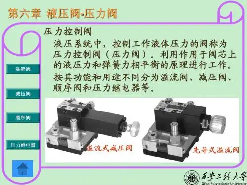
9.分类压力阀按功能和用途可分为溢流阀、减压阀、顺序阀、平衡阀等,有时把将油液压力信号转换为电信号的压力继电器也归入压力阀中。
它们所依据的基本工作原理,是利用阀芯上的液体压力对阀芯的作用力与其它作用力(主要是弹簧力)的平衡条件,来调节阀的开口量,调节压力或产生动作。
1.溢流阀在定量泵供油的液压系统中,执行元件拖动负载的速度由节流阀来控制。
由于液压泵输出的流量大于液压缸所需的流量,使节流阀前的油压升高,因此必须在系统中与泵并联一个溢流阀2.溢流阀的性能溢流阀的静态特性,是指溢流阀在稳定工作状态下的压力-流量特性、调压范围及压力稳定性等。
Materialsand ListingsOPW 301Emergency VentsThe OPW 301 Emergency Vent isLid: Cast iron with AST Phase 1 Enhanced Vapor Recovery (EVR) SystemTable 1Emergency Venting Size Selection GuideFor Horizontal Above Ground Storage TanksThe OPW AST Venting Guide is supplied to assist emergency venting selection for above ground storage tanks (AST). The table below contains common tank sizes and based on the Wetted Area of a horizontal cylindrical storage tank, the correct size OPW Emergency Vent . The following chart, was taken directly from NPFA 30 and UL 142.Horizontal AST Emergency Venting Size Guide – Table 1Capacity Diameter LengthWetted Area Required Vent Capacity OPW 301 Vent SizeGallons Liters ft. or in.Meters ft. or in.Meters sq. ft.sq. m.CFH CMHHorizontal AST Emergency Vent SelectionFor Horizontal Above Ground Storage TanksTABLE 1 is a pre-calculated chart that may have all the information needed to choose the proper emergency vent. If the tank size is not in the pre-calculated chart, use the example below as a guide to figure out the wetted area, cubic feet per hour (CFH), and proper vent selection for the particular tank.**EXAMPLE:Given: Tank capacity is 10,000 gallons; 10 feet in diameter x 17 feet long.Step 1From TABLE 1: WA = 518 sq. ft.If not in the table, do the following to calculate the wetted area:p d24p d 22Formula: WA=.75 2 + pdl =.75 + pdlWA = wetted area in square feet75% = horizontal tank factor p = 3.14d = diameter of tank end in feet l = length of tank in feet3.14 x1022WA=.75 + (3.14 x 10 x 17)WA=.75 (157.0 + 533.8) = 518 square feet rounded Step 2If the tank size is in the chart, use the supplied CFH values to determine theemergency vent size needed in TABLE 1.If not in the charts, continue the following example:Using 518 square feet, the cubic feet per hour (CFH) can be found using TABLE 1.Since 518 falls between the values of 500 and 600, interpolation is necessary as follows:See TABLE 2 for additional CFH values.600 sq. ft. 392,000 CFH -500 sq. ft. -354,000 CFH Difference: 100 sq. ft.38,000 CFH38,000 x100518-500; x =6,840 CFHTotal CFH required = 354,000 CFH + 6,840 CFH = 360,840 CFH Step 3Vent selection: using TABLE 1, find the range in which 360,840 CFH falls. The tables show that an 8" emergency vent is needed. **PEI Recommended Practices 200-96Wetted Area vesus Cubic Feet of Free Air Per Hour Table 2(14.7 PSIA and 60°)SOURCE: Flamable and Combustible Liquids Code 30, NFPA.Interpolate for immediate values.。
安全阀工艺计算1 安全阀工艺计算1.1 操作参数1.1.1 最高操作压力P(表):设备运行期间可能达到的最高压力,一般应按不同工艺过程确定。
1.1.2 安全阀定压P s:安全阀的开启压力。
安全阀定压P s(表)必须等于或稍小于设备设计压力P D(表);由不同工艺操作压力和设备设计压力确定。
当安全阀定压P s=设备设计压力时,当P≤1.8MPa(表)时,P s=P D+0.1=P+0.18+0.1当1.8<P≤4MPa(表)时,P s=P D+0.1=1.1P+0.1当4<P≤8MPa(表)时,P s=P D+0.1=P+0.4+0.1当P>8MPa(表)时,P s=P D+0.1=1.05P+0.1 (1-1)注:P D(表):设备设计压力;P s(表):安全阀定压;P D(表):设备设计压力;P(表):设备最高操作压力;1.1.3 积聚压力Pa(表):安全阀排放介质过程中,允许压力增加超过设备的设计压力的数值,可按表1.1选取表1.1 定压和积聚压极限1.1.4容许过压P h(表):容许压力增加超过定压的数值。
如果定压等于设计压力:P s=P D,则P h=P a+P D-P s如果定压小于设计压力:P s<P D,则P h=P a+P D-P s(1-2)1.1.5最高泄放压力P m(绝):安全阀达到最大泄放能力时的压力。
一般按如下计算:P m=P a+P a(1-3)1.1.6 背压P2(安全阀出口压力)背压是由于排放系统有压力而存在于安全阀出口的压力,它是迭加背压(安全阀开启前泄压总管的压力)和积聚背压(积聚背压是在安全阀开启后,由于介质流动所增加的压力)的总和。
对于普通型(非平衡型)安全阀:P2≤10%P S1.1.7 回座压差:是安全阀的定压与关闭压力的差值,以定压的百分数或压力单位表示。
P D<回座压力<P S1.1.8 安全阀的压力等级关系(即容器设计压力,安全阀容许积聚压、定压、注:1、与ASME锅炉压力容器规程和《压力容器安全技术监察规程,1990》基本一致;2、所示压力条件是安装在容器的安全阀条件;3、操作压力可高于或低于90%;4、回座和压差应参照ASME规程有关章节。
Instruction ManualPU/PI and PS10Differential PressureTransducershalstrup-walcher GmbHStegener Straße 10D-79199 KirchzartenGermanyPhone: +49 (0) 76 61/39 63–0Fax: +49 (0) 76 61/39 63–99E-Mail: *************************Internet: Document 7100.001784 Version 5.3 02/2010PU/PI and PS10 Instruction ManualTable of Contents1 Safety precautions (4)1.1 Appropriate use (4)1.2 Shipping, assembly, electrical connections and start-up (4)1.3 Troubleshooting, maintenance, repairs, disposal (4)1.4 Symbols (5)2 Instrument description (6)3 Start-up (6)3.1 Features (6)3.2 Supply voltage connections in the instrument: (7)3.3 Analog output connections in the instrument (7)4 Calibrating the zero point (8)5 Troubleshooting (9)6 Technical data (10)7 Dimension drawings (12)PU/PI and PS10 Instruction ManualPurpose of instruction manualThis instruction manual describes the features of the PU/PI and PS10 differential pressure transducers and provides guidelines for their use.Improper use of this instrument or failure to follow these instructions may cause injury or equipment damage. Every person who uses the device must therefore read the manual and understand the possible risks. The instruction manual, and in particular the safety precautions contained therein, must be followed carefully. Contact the manufacturer if you do not understand any part of this instruction manual. Handle this manual with care:∙It must be readily available throughout the lifecycle of the instrument.∙It must be provided to any individuals who assume responsibility for operating the instrument at a later date.∙It must include any supplementary materials provided by the manufacturer.The manufacturer reserves the right to continue developing this instrument model without documenting such development in each individual case. The manufacturer will be happy to determine whether this manual is up-to-date.ConformityThis instrument corresponds to the state of the art and meets all legal requirements set forth in EC directives as evidenced by the CE label.© 2005The manufacturer owns the copyright to this instruction manual. This manual contains data, instructions and drawings pertaining to the features and usage of this instrument; copying this manual in part or in full or distributing it to third parties is prohibited.PU/PI and PS10 Instruction Manual1 Safety precautions1.1 Appropriate useIn addition to differential pressure data, the PU/PI and PS10 differential pressure transducers also record positive and negative overpressures.Always observe the operating requirements—particularly the permissible supply voltage—indicated on the rating plate and in the "Technical data” section of this manual.The instrument may only be handled as indicated in this manual. Modifications to the instrument are prohibited. The manufacturer is not liable for damages caused by improper use or failure to follow these instructions. Violations of this type render all warranty claims null and void.1.2 Shipping, assembly, electrical connections and start-upDo not close the pressure inputs when shipping, as changes in barometric pressure could damage instruments with low measuring ranges.Only technical personnel who are appropriately trained and authorized by the operator of the facility may assemble the instrument and set up its electrical connections.The instrument may only be operated by appropriately trained individuals who have been authorized by the operator of the facility.Pressurized air or breath is not to be used for performance tests, as this could damage instruments with low measurement ranges.Measurement errors may occur if the instrument is not kept protected from sunlight. Specific safety precautions are given in individual sections of this manual.1.3 Troubleshooting, maintenance, repairs, disposalThe individual responsible for the electrical connections must be notified immediately if the instrument is damaged or if errors occur that cannot be corrected as indicated in section 5.This individual must take the instrument out of service until the error has been corrected and ensure that it cannot be used unintentionally.Always unplug the supply voltage before opening the instrument!This instrument requires no maintenance.Only the manufacturer may perform repairs that require the housing to be opened.PU/PI and PS10 Instruction ManualThe electronic components of the instrument contain environmentally hazardous materials and materials that can be reused. For this reason the instrument must be recycled in accordance with the environmental guidelines of the jurisdiction in question once it has been taken permanently out of service.1.4 SymbolsThe symbols given below are used throughout this manual to indicate instances when improper operation could result in the following hazards:WARNING! This warns you of a potential hazard that could lead to bodily injury up to and including death if the corresponding instructions are not followed.WARNING: This warns you of a potential hazard that could lead to significant property damage if corresponding instructions are not followed.INFORMATION This indicates that the corresponding information is important for operating the instrument properly.PU/PI and PS10 Instruction Manual2 Instrument descriptionThe PU/PI and PS10 pressure transducers are pneumatic, electronic sensors for measuring overpressures, vacuum pressures and differential pressures. Typical applications include, for instance, pressure measurements in air-conditioning and ventilation ducts. At the heart of the transducer is a pressure measurement capsule with a beryllium bronze membrane spring, which is displaced by the pressure difference between the two chambers of the measurement capsule. Inductive displacement transducers measure membrane deflection without contacting the membrane. The instrument has no frictional parts or parts subject to mechanical wear.3 Start-up3.1 FeaturesAlthough the PU/PI and PS 10 pressure transducers are highly robust, they are nevertheless precision instruments and should be handled with care. Avoid mounting the instruments in the direct vicinity of any sources of radiation or heat, such as heaters, as this could result in measurement errors. Ideally, the instrument should be mounted vertically on a wall not subject to vibration. Pressure (+) and vacuum (-) ports should be pointing down in order to prevent any condensation from entering the measurement cell.When connecting pressure to the transducer, use the following table to ensure that the sign of the pressure (+ or -) is correct.PU/PI and PS10 Instruction Manual3.2Supply voltage connections in the instrument:Figure 1: Configuration of circuit board: (not all components are shown)P0Observe the required supply voltage (see rating plate) as well as the connection diagram located on the housing cover / circuit board mount. 3.3Analog output connections in the instrumentThe transducer outputs are protected from short circuits. Instruments supplied with direct current are also protected from reverse polarityPU/PI and PS10 Instruction ManualDisplay-connector4 Calibrating the zero pointPlease remember that it takes roughly 30 to 60 minutes for the pressuretransducer to warm up after it is switched on. The output signal may notremain stable during this period.It is recommended that the zero point after a long operating time(approximately 6 months) is checked and if necessary calibrate it again.The wiring of the current outputmakes it impossible to enter a negative current.As a result, operators cannot turn the zero-point potentiometer beyond the0.0 mA mark when calibrating the zero point. Were this not the case, thenegative component, which cannot be displayed, would interfere with theoutput signal.After the pressure transducer has warmed up, the operator may calibrate the zeropoint using the P0 trimmer (see figure 1). The following table may be used to look up the value to which the analog output must be set when the ports are open; this value is dependent upon both the measurement range and the output signal.PU/PI and PS10 Instruction Manual 5 TroubleshootingPU/PI and PS10 Instruction Manual 6 Technical dataPU/PI and PS10 Instruction ManualAppendix A: Parts in contact with measurement medium∙ Beryllium bronze CuBe2 ∙ Araldite CY236 / HY988∙ Mu metal (nickel alloy) ∙ Loctite 242e∙ Brass CuZn39Pb3 ∙ Carbonyl iron∙ Aluminum AlCuMgPb / AlMg3 ∙ KEL (FPM: fluorinated rubber) ∙ Silicon (tubing) optional: Viton ∙ Vepuran Vu 4457/51∙ Crastin (PTBP) ∙ UHU-Plus endfest 300 binder。