ULN2003纯中文资料
- 格式:pdf
- 大小:326.28 KB
- 文档页数:8
These versatile devices are useful for driving a wide range of loads including solenoids, relays DC motors, LED displays filament lamps, thermal printheads and high power buffers.
ULN2003资料
ULN2001A-ULN2002A
®
ULN2003A-ULN2004A
SEVEN DARLINGTON ARRAYS
. SEVEN DARLINGTONS PER PACKAGE . OUTPUT CURRENT 500mA PER DRIVER
(600mA PEAK)
. OUTPUT VOLTAGE 50V . INTEGRATED SUPPRESSION DIODES FOR
The ULN2001A/2002A/2003A and 2004A are supplied in 16 pin plastic DIP packages with a copper leadframe to reduce thermal resistance. They are available also in small outline package (SO-16) as ULN2001D/2002D/2003D/2004D.
INDUCTIVE LOADS
. OUTPUTS CAN BE PARALLELED FOR HIGHER CURRENT
. TTL/CMOS/PMOS/DTL COMPATIBLE INPUTS . INPUTS PINNED OPPOSITE OUTPUTS TO
SIMPLIFY LAYOUT
DIP16 ORDERING NUMBERS: ULN2001A/2A/3A/4A
Input Current Input Voltage
DC Forward Current Gain Input Capacitance Turn-on Delay Time Turn-off Delay Time Clamp Diode Leakage Current Clamp Diode Forward Voltage
inch TYP. MAX.
a1 0.51
0.020
B 0.77
1.65 0.030
0.065
b
0.5
0.020
b1
0.25
0.010
D
20
0.787
E
8.5
0.335
e
2.54
0.100
e3
17.78
0.700
F
7.1
0.280
I
5.1
0.201
L
3.3
0.130
Z
1.27
0.050
OUTLINE AND MECHANICAL DATA
DIP16
6/8
ULN2001A - ULN2002A - ULN2003A - ULN2004A
mm DIM.
inch
MIN. TYP. MAX. MIN. TYP. MAX.
A
1.75
0.069
a1 0.1
0.25 0.004
0.009
a2
1.6
0.063
b 0.35
0.46 0.014
0.018
THERMAL DATA
Symbol Rth j-amb
Parameter Thermal Resistance Junction-ambient
Value
Unit
50
V
30
V
500
mA
25
mA
– 20 to 85
°C
– 55 to 150
°C
150
°C
Max.
DIP16 70
SO16 120
Unit °C/W
300
D96IN454
Tj=25˚C Max
200
TYPICAL 100
0 0
100 200 300 400 500 Ib(µA)
200 TYPICAL
100
0
0.0
0.5
1.0
1.5 Vce(sat)
Figure 10: Peak Collector Current versus Duty Cycle
7/8
ULN2001A - ULN2002A - ULN2003A - ULN2004A
Information furnished is believed to be accurate and reliable. However, STMicroelectronics assumes no responsibility for the consequences of use of such information nor for any infringement of patents or other rights of third parties which may result from its use. No license is granted by implication or otherwise under any patent or patent rights of STMicroelectronics. Specification mentioned in this publication are subject to change without notice. This publication supersedes and replaces all information previously supplied. STMicroelectronics products are not authorized for use as critical components in life support devices or systems without express written approval of STMicroelectronics.
Series ULN-2002A (each driver)
Series ULN-2003A (each driver)
Series ULN-2004A (each driver)
ABSOLUTE MAXIMUM RATINGS
Symbol Vo Vin Ic Ib Tamb Tstg Tj
Parameter Output Voltage Input Voltage (for ULN2002A/D - 2003A/D - 2004A/D) Continuous Collector Current Continuous Base Current Operating Ambient Temperature Range Storage Temperature Range Junction Temperature
Figure 8: Collector Current versus Input Current
Figure 9: Collector Current versus Saturation Voltage
Ic (mA) 500
400
300
Tj=25˚C Max
D96IN453
Ic (mA) 500
400
DESCRIPTION
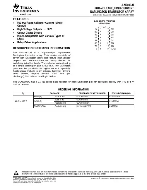
The ULN2001A, ULN2002A, ULN2003 and ULN2004A are high voltage, high current darlington arrays each containing seven open collector darlington pairs with common emitters. Each channel rated at 500mA and can withstand peak currents of 600mA. Suppression diodes are included for inductive load driving and the inputs are pinned opposite the outputs to simplify board layout.
February 2002
SO16 ORDERING NUMBERS: ULN2001D/2D/3D/4D
PIN CONNECTION
1/8
ULN2001A - ULN2002A - ULN2003A - ULN2004A
SCHEMATIC DIAGRAM
Series ULN-2001A (each driver)
Test Conditions
VCE = 50V Tamb = 70°C, VCE = 50V
Min. Typ.
VCE(sat) Ii(on)
Ii(off) Vi(on)
hFE Ci tPLH tPHL IR VF
Collector-emitter Saturation Voltage Input Current
2/8
ULN2001A - ULN2002A - ULN2003A - ULN2004A
ELECTRICAL CHARACTERISTICS (Tamb = 25oC unless otherwise specified)
Symbol ICEX
Parameter Output Leakage Current
2
V7
3/8
ULN2001A - ULN2002A - ULN2003A - ULN2004A
TEST CIRCUITS Figure 1a.