Autotrol产品手册(总-简单)
- 格式:doc
- 大小:7.98 MB
- 文档页数:17
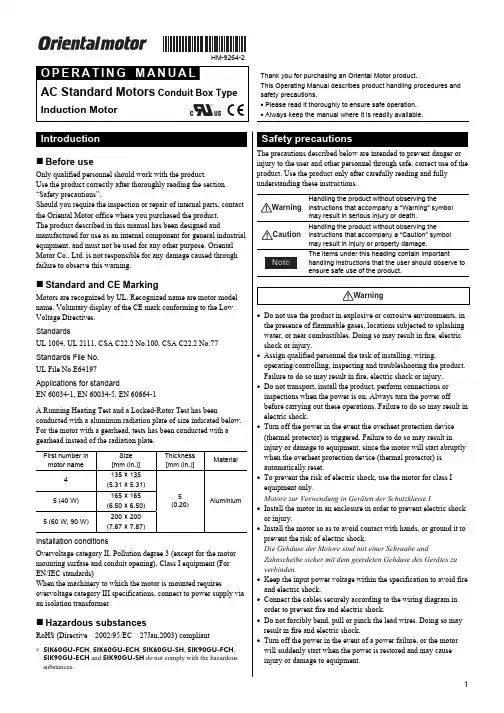
HM-9264-2AC Standard Motors Conduit Box TypeInduction MotorThank you for purchasing an Oriental Motor product.This Operating Manual describes product handling procedures and safety precautions.• Please read it thoroughly to ensure safe operation. • Always keep the manual where it is readily available.Before useOnly qualified personnel should work with the product.Use the product correctly after thoroughly reading the section “Safety precautions”.Should you require the inspection or repair of internal parts, contact the Oriental Motor office where you purchased the product. The product described in this manual has been designed andmanufactured for use as an internal component for general industrial equipment, and must not be used for any other purpose. Oriental Motor Co., Ltd. is not responsible for any damage caused through failure to observe this warning.Standard and CE MarkingMotors are recognized by UL. Recognized name are motor model name. Voluntary display of the CE mark conforming to the Low Voltage Directives. StandardsUL 1004, UL 2111, CSA C22.2 No.100, CSA C22.2 No.77 Standards File No. UL File No.E64197 Applications for standardEN 60034-1, EN 60034-5, EN 60664-1A Running Heating Test and a Locked-Rotor Test has beenconducted with a aluminum radiation plate of size indicated below. For the motor with a gearhead, tests has been conducted with a gearhead instead of the radiation plate.First number in motor nameSize [mm (in.)] Thickness [mm (in.)]Material4 135 × 135 (5.31 × 5.31) 5 (40 W) 165 × 165 (6.50 × 6.50) 5 (60 W, 90 W)200 × 200 (7.87 × 7.87)5 (0.20)AluminiumInstallation conditionsOvervoltage category II, Pollution degree 3 (except for the motor mounting surfase and conduit opening), Class I equipment (For EN/IEC standards)When the machinery to which the motor is mounted requiresovervoltage category III specifications, connect to power supply via an isolation transformer.Hazardous substancesRoHS (Directive 2002/95/EC 27Jan.2003) compliant∗ 5IK60GU-FCH , 5IK60GU-ECH , 5IK60GU-SH , 5IK90GU-FCH , 5IK90GU-ECH and 5IK90GU-SH do not comply with the hazardous substances.The precautions described below are intended to prevent danger or injury to the user and other personnel through safe, correct use of the product. Use the product only after carefully reading and fully understanding these instructions.WarningHandling the product without observing theinstructions that accompany a “Warning” symbol may result in serious injury or death.CautionHandling the product without observing theinstructions that accompany a “Caution” symbol may result in injury or property damage.NoteThe items under this heading contain importanthandling instructions that the user should observe to ensure safe use of the product.Warning• Do not use the product in explosive or corrosive environments, in the presence of flammable gases, locations subjected to splashing water, or near combustibles. Doing so may result in fire, electric shock or injury.• Assign qualified personnel the task of installing, wiring,operating/controlling, inspecting and troubleshooting the product. Failure to do so may result in fire, electric shock or injury. • Do not transport, install the product, perform connections or inspections when the power is on. Always turn the power offbefore carrying out these operations. Failure to do so may result in electric shock.• Turn off the power in the event the overheat protection device (thermal protector) is triggered. Failure to do so may result in injury or damage to equipment, since the motor will start abruptly when the overheat protection device (thermal protector) is automatically reset.• To prevent the risk of electric shock, use the motor for class I equipment only.Motore zur Verwendung in Geräten der Schutzklasse I.• Install the motor in an enclosure in order to prevent electric shock or injury.• Install the motor so as to avoid contact with hands, or ground it to prevent the risk of electric shock.Die Gehäuse der Motore sind mit einer Schraube undZahnscheibe sicher mit dem geerdeten Gehäuse des Gerätes zu verbinden.• Keep the input power voltage within the specification to avoid fire and electric shock.• Connect the cables securely according to the wiring diagram in order to prevent fire and electric shock.• Do not forcibly bend, pull or pinch the lead wires. Doing so may result in fire and electric shock.• Turn off the power in the event of a power failure, or the motor will suddenly start when the power is restored and may cause injury or damage to equipment.• Do not touch the connection terminal of the capacitor immediately after the power is turned off (for a period of 30 seconds). Theresidual voltage may cause electric shock.• Do not disassemble or modify the motor. This may cause electric shock or injury.Caution• Do not use the motor beyond its specifications, or electric shock, injury or damage to equipment may result.• Do not touch the motor during operation or immediately after stopping. The surface is hot and may cause a burn.• Do not hold the motor output shaft or motor lead wires. This may cause injury.• Keep the area around the motor free of combustible materials in order to prevent fire or a burn.• To prevent the risk of damage to equipment, leave nothing around the motor that would obstruct ventilation.• To prevent bodily injury, do not touch the rotating parts (output shaft, cooling fan) of the motor during operation.• When an abnormality is noted, turn off the power immediately, or fire, electric shock or injury may occur.• The motor’s surface temperature may exceed70 °C, even under normal operating conditions. Ifa motor is accessible during operation, post thewarning label shown in the figure in aconspicuous position to prevent the risk of skinburn(s).Warning label• To dispose of the motor, disassemble it into parts and components as much as possible and dispose of individual parts/components as industrial waste.Checking the productVerify that the items listed below are included. Report any missing or damaged items to the branch or sales office from which you purchased the product.• Motor...............................................1 unit• OPERATING MANUAL................1 copyChecking the model nameCheck the model number against the number indicated on the product.Model Model Model4IK25GN-FCH 4IK25GN-ECH 4IK25GN-SH4IK25AA-FCH 4IK25AA-ECH 4IK25AA-SH5IK40GN-FCH 5IK40GN-ECH 5IK40GN-SH5IK40AA-FCH 5IK40AA-ECH 5IK40AA-SH5IK60GE-FCH 5IK60GE-ECH 5IK60GE-SH5IK60A-FCH 5IK60A-ECH 5IK60A-SH5IK60GU-FCH 5IK60GU-ECH 5IK60GU-SH5IK90GE-FCH 5IK90GE-ECH 5IK90GE-SH5IK90A-FCH 5IK90A-ECH 5IK90A-SH5IK90GU-FCH 5IK90GU-ECH 5IK90GU-SH Location for installationThe motor is designed and manufactured for installation in equipment.Install it in a well-ventilated location that provides easy access for inspection. The location must also satisfy the following conditions: • Inside an enclosure that is installed indoors (provide vent holes) • Operating ambient temperature−10 to +40 °C (+14 to +104 °F) (non-freezing)−10 to +50 °C (+14 to +122 °F) for three-phase 200 V• Operating ambient humidity 85%, maximum (non-condensing) • Area that is free from an explosive atmosphere or toxic gas (such as sulfuric gas) or liquid• Area not exposed to direct sun• Area free of excessive amount dust, iron particles or the like• Area not subject to splashing water (storms, water droplets), oil (oil droplets) or other liquids• Area free of excessive salt• Area not subject to continuous vibration or excessive shocks• Area free of excessive electromagnetic noise (from welders,power machinery, etc.)• Area free of radioactive materials, magnetic fields or vacuum• 1000 m (3300 ft.) or less above sea levelHow to install the motor• Round shaft typeDrill holes on the mounting plate and fix the motor on the plateusing screws, nuts, and washers (not supplied). Be careful there is nogap between the motor installation surface and the bracket.First number inmotor modelScrew size Tightening torque [N·m (lb-in)]4 M5 2.5(22)5 M6 3.0(26)Do not insert the motor into the mounting hole at anangle or force it in, as this may scratch the flange pilotsection and damage the motor.• Pinion shaft typeDrill holes on the mounting plate and fix the motor and gearhead on the plate using screws supplied with the gearhead. Be careful there is no gap between the motor flange and the gearhead.For details of installation, see the operating manual provided with the gearhead, which is sold separately.Use the gearhead with pinion shaft which is identicalwith one of motor.• Motor with cooling fanWhen installing a motor with cooling fan onto a device, leave10 mm (0.39 in.) or more behind the fan cover or open a ventilation hole so that the cooling inlet on the back of the motor cover is not blocked.Insulate all the wire connections, such as the connection between the motor and the capacitor connection.When the single-phase motor is run in only one direction, unused lead wires should be insulated.Ground the motor using a Protective Earth lead wire (green/yellow). The direction of motor rotation is as viewed from the side of the motor’s output shaft. The motor rotates in a clockwise (CW) and counterclockwise (CCW) direction.• Insulation class of this motor is B. Make sure that themotor case temperature does not exceed 90 °C(194 °F) during operation of the motor. Operationexceeding case temperature 90 °C (194 °F) maysignificantly deteriorate the coils and ball bearings ofthe motor and shorten the motor’s life span. Motorcase temperature can be measured by fixing athermometer on the motor surface. It can also bemeasured using thermo tape or a thermocouple.• To change rotation direction of the single-phasemotor, wait until the motor completely stops.Otherwise its direction may not change or may takemuch time to change.Rotating direction of the gearhead output shaftThe rotating direction of the gearhead output shaft may be opposite that of the motor shaft, depending on the gear ratio. For the rotating direction of the output shaft of a specific gearhead used, refer to the operating manual for the gearhead. Connection method to a terminal box• Open the terminal box and connect wires.• Use applicable cable ground and conduit for conduit opening. • After connecting, close the terminal box with the terminal cover. • Terminal cover screws tightening torqueSingle-phase 25 W, 40 W/Three-phase: 0.3 N·m (2.6 lb-in) Single-phase 60 W, 90 W: 1 N·m (8.8 lb-in)• Single-phase 25 W, 40 W/Three-phase••Connect the motor according to the figure.The connection method will vary, depending on the directionClockwiseLNCounterclockwiseLN∗ NC: Not connect. Three-phase motorsConnect the motor according to the figure.When connected according to the connection diagram, the motor will operate in the clockwise direction (CW) as viewed from the motor’s output shaft. To change the direction of rotation, change any two connections between U, V and W.ClockwiseL2 (S)L1 (R)L3 (T)Motors have a continuous rating.This motor is equipped with the feature listed below to prevent the motor from burning out as a result of abnormal heating which maybe caused by misapplication.• Thermal protection“TP” is stamped on the motor nameplate. The motor has an “auto reset” type thermal protector built into its motor coil. When themotor reaches a predetermined temperature, the internal thermal protector is activated and the motor is stopped.Always turn the power off before performing inspections.Thermal protector activation rangePower is turned off at 130±5 °C (266±9 °F)Power is turned back on at 82±15 °C (180±27 °F)When the motor cannot be operated correctly, refer to the contents provided in this section and take appropriate action. If the problem persists, contact your nearest office.Phenomena CheckitemsMotor does not rotate or rotates slowly. • Check the power supply voltage.• Connect the power supply and the motor correctly.• If terminal blocks or crimp terminals are used, check them for poor connection. • Keep the load at or below the allowable value.Motor sometimes rotates and stops. • Connect the power supply and the motor correctly.• If terminal blocks or crimp terminals are used, check them for poor connection.The motor rotates in the direction opposite to the specified direction. • Connect correctly by referring to “Wiring diagram.”• The rotating direction of the motor output shaft may be different from that of the gearhead output shaft depending on the gear ratio of the gearhead. See the operating manual for the gearhead.• The rotating direction is indicated as viewed from the motor output shaft. Check the reference direction.Motor temperature abnormally high [Motor case temperature exceeds 90 °C (194 °F)] • Check the power supply voltage. • Review the ventilation condition.Noisy operation • Assemble the motor and gearheadcorrectly by referring to the operatingmanual for the gearhead.• Assemble a gearhead of the same piniontype as the motor.• Unauthorized reproduction or copying of all or part of thismanual is prohibited.• Oriental Motor shall not be liable whatsoever for any problems relating to industrial property rights arising from use of anyinformation, circuit, equipment or device provided orreferenced in this manual.• Characteristics, specifications and dimensions are subject tochange without notice.• While we make every effort to offer accurate information in the manual, we welcome your input. Should you find uncleardescriptions, errors or omissions, please contact the nearestoffice.• is a registered trademark or trademark ofOriental Motor Co., Ltd., in Japan and other countries.© Copyright ORIENTAL MOTOR CO., LTD. 2008Printed on Recycled Paper • Please contact your nearest Oriental Motor office for further information.Headquarters Tokyo, JapanTel:(03)3835-0684 Fax:(03)3835-1890Tel:01 47 86 97 50 Fax:01 47 82 45 16Tel:(02)8228-0707 Fax:(02)8228-0708 Technical Support Tel:(800)468-39828:30 A.M. to 5:00 P.M., P.S.T. (M-F)7:30 A.M. to 5:00 P.M., C.S.T. (M-F)E-mail:*****************************Headquarters and Düsseldorf Office Tel:0211-52067-00 Fax:0211-52067-099 Munich Office Tel:089-3181225-00 Fax:089-3181225-25 Hamburg Office Tel:040-76910443 Fax:040-76910445Tel:01256-347090 Fax:01256-347099Tel:02-93906346 Fax:02-93906348Tel:(6745)7344 Fax:(6745)9405KOREATel:(032)822-2042~3 Fax:(032)819-8745Tel:(03)22875778 Fax:(03)22875528Tel:66-2-254-6113 Fax:66-2-254-6114。
HIROSS恒温恒湿机房精密空调操作手册HIMOD系列北京****科技有限公司技术部2009年01月01日目录第一章HIMOD系列海洛斯空调概述 (2)型号多 (3)控制技术先进 (3)制冷系统 (3)送风系统 (3)加湿系统 (3)加热系统 (4)1.7其它 (4)第二章HIMOD系列海洛斯空调型号含义 (4)第三章有关空调的一些资料 (5)气流组织方式(详见下图) (5)盖板纽开启方式(详见下图) (5)空调重量(单位:Kg) (5)机组尺寸及维护空间 (6)第四章制冷循环管路示意图 (7)风冷却(A型) (7)水冷却(W型) (8)双冷源(D型) (9)单系统(C型) (10)双系统(C型) (10)第五章调速风机调速接线示意图 (11)第六章MICROF ACE概述 (12)概述 (12)面板简介液晶显示屏 (13)液晶显示屏介绍 (13)第七章MICROF ACE面板的操作 (13)第八章控制器的使用 (14)控制器(HIROMATIC)概述 (14)控制器的操作 (15)菜单结构 (17)第九章日常维护及特殊维护 (18)日常维护 (18)特殊维护 (19)第十章常见报警及处理 (20)低压报警 (20)高压报警 (21)加湿报警 (21)失风报警 (21)电加热过热报警 (22)显示器发黑 (22)空调不制冷 (22)附录1:参数列表 (22)附录2:报警内容列表 (26)附录3:各菜单项含义: (28)第一章HIMOD系列海洛斯空调概述HIMOD系列海洛斯空调(HIMOD空调)是当今世界上最先进的机房专用恒温恒湿机房专用精密空调。
随着IT业的突飞猛进的发展,各种布局、面积差别很大的机房如雨后春笋般纷纷出现了,使用环境也不一而同。
为适应各种不同要求的机房,新开发的海洛斯HIMOD系列空调应运而生。
她是在保留她的前一代产品HIRANGE系列机房空调的优点,又应用了当今世界上提高了的制冷技术及制冷部件制造工艺,使用当今最先进的模块化设计理念生产出来的高科技机房空调产品。
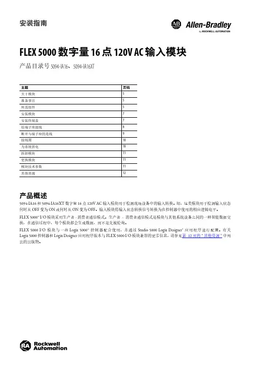
安装指南FLEX 5000 数字量 16 点 120V AC 输入模块产品目录号 5094-IA16、5094-IA16XT产品概述5094-IA16 和 5094-IA16XT 数字量 16 点 120V AC 输入模块用于检测现场设备中的输入转换。
即,这类模块用于检测输入状态何时从 OFF 变为 ON 或何时从 ON 变为 OFF 。
输入模块将输入状态转换信号转换为在控制器中使用的相应逻辑电平。
FLEX 5000™ I/O 模块采用生产者 - 消费者通信模式。
生产者-消费者通信模式是模块与其他系统设备之间的一种智能数据交换,在通信过程中,每个模块都会生成数据,而不是先被轮询。
FLEX 5000 I/O 模块与一些 Logix 5000™ 控制器配合使用,并通过 Studio 5000 Logix Designer® 应用程序进行配置。
有关Logix 5000 控制器和 Logix Designer 应用程序版本与 FLEX 5000 I/O 模块兼容的更多信息,请参见第12页的“其他资源”中列出的出版物。
主题页码关于模块5准备事宜5所需组件5安装模块7安装终端盖7给端子座接线8断开与端子座的连线9接线图10为系统供电10拆卸模块11更换模块11模块技术参数11其他资源122罗克韦尔自动化出版物 5094-IN025A-ZH-P - 2019 年 12 月FLEX 5000 数字量 16 点 120V AC 输入模块 安装指南ATTENTION:Read this document and the documents listed in the Additional Resources section about installation, configuration and operation of this equipment before you install, configure, operate or maintain this product. Users are required to familiarize themselves with installation and wiring instructions in addition to requirements of all applicable codes, laws, and standards.Activities including installation, adjustments, putting into service, use, assembly, disassembly, and maintenance are required to be carried out by suitably trained personnel in accordance with applicable code of practice. If this equipment is used in a manner not specified by the manufacturer, the protection provided by the equipment may be impaired.注意:在安装、配置、操作和维护本产品前,请阅读本文档以及“其他资源”部分列出的有关设备安装、配置和操作的相应文档。
Autotrol控制器总览:控制器是用来根据设定好的流程控制阀门的动作的器件,Autotrol的控制器是可以与阀门完全分离开的,这样更便于维护和调整。
Autotrol的控制器主要有:400系列:440、450、460、480、480QC900系列:940、942、950、960、964、966、962、962M+S700(Logix)系列:740、742、760、762按功能特征主要可分为时间型、脉冲型和流量型三大类,一般情况下,三位数中间为4的为时间型,中间一位为5的为脉冲型,其他的为流量型。
时间型:440、440i、940和942型控制器是操作简便的机械式程序控制器,其再生步骤是固定不变的。
用户可以选择哪一个或多个星期天进行再生程序,一旦选择了某天,当控制器到了预先指定的时间(440、440i型为2:30am;940和942型为2:00am),再生程序便自动启动。
控制器本身也备有再生旋钮,用户可以选择随时启动再生程序。
电子流量型控制器460i、960、962备有自动统计水量的功能,用户只需要输入进水总硬度、软水器总交换能力等资料后,控制器在每天的凌晨2:00计算过去7天的用水量而得到一个平均值作为接下来一天的用水量,然后比较剩余的产水能力是不是足够供应一天的需求,如果设备剩余的产水容量不够,便自动引发一次再生;控制器也可以提供“处理水量达到某个预先输入的参数时,立即启动再生程序”的模式,以便软化器随时进行再生程序。
460i型控制器的再生步骤是固定不变的,可以配合255和268系列多路阀使用,960型控制器只适用于255和268系列多路阀,962型适用于273、278、180和Magnum系列多路阀,其每个再生步骤都是可调的。
964型控制器是一用一备型的,其特点是在运行时可以看到瞬间的产水流量和剩余的产水能力,当再生时可以看到剩余的再生时间。
另外,964型控制器可以看到过去7天的用水量等参数。
目录1 AutoPlant软件简介 (2)2 AutoPlant软件二次开发成果 (3)2.1 元件库 (3)2.2 等级库 (4)2.3 单管图配置 (4)2.4 报表格式RPT文件 (4)2.5 非标设备及管件的定制成果 (4)3 AutoPlant软件二次开发成果的使用 (4)3.1 元件库的使用 (4)3.2 等级库的使用 (5)3.3 单管图配置的修改 (6)3.4 报表格式RPT文件的配置 (7)3.5 非标设备及管件的使用 (10)4 问题及建议 (13)AutoPlant数据库使用简明手册1A UTO P LANT软件简介AutoPlant产品由美国BENTLEY公司(原属美国REBIS公司,为AUTOCAD 平台全球第一大开发商)出品,运行在AutoCAD2000-2008平台上的工厂设计软件。
该软件可在真实的三维环境下进行设计,模型建立过程智能性强,符合设计人员思维习惯。
建模完成后,可对模型进行碰撞检查和实时漫游,最大程度地减少设计中的错、漏、碰、缺现象,并可迅速地生成平、立、剖面图,全自动地生成单管图和精确的材料统计表等设计资料。
AutoPlant工厂设计软件的产品,主要包括以下程序模块:序号名称描述1 Bentley Plant P&ID 智能工艺流程设计系统2 Data Manager 工艺数据管理器3 AutoPLANT Piping 三维管道设计系统4 AutoPLANT Equipment 三维设备建模系统5 AutoPLANT Structural 三维钢结构建模系统6 ProjectWise Navigator 实时漫游浏览7 AutoPIPE 管道应力分析1)P&ID智能工艺流程设计系统工艺软件包为用户制作智能工艺图表提供了一套独特的工具。
工艺软件包中的模块均应用工业的标准技术,比如:AutoCAD、 MS Office以及ODBC的数据库驱动。

支持服务产品系列适用范围无论您的业务目标是什么,罗克韦尔自动化支持服务均能帮助您挖掘运营潜能。
借助每一份支持协议带来的高价值工具以及我们训练有素的专家团队,您能够减少维护时间及成本,并提高整体设备效率。
了解更多信息生命周期服务咨询我们的工程师在罗克韦尔自动化软件门户网站购买的软件包括一份独立的支持合同,其终止日期与 TechConnect 协议的签署周年日期保持一致。
在罗克韦尔自动化商业网站上续订所购软件时,将提供单独的协议。
标准产品产品系列 (例如自动化控制系统) 中列出的全部产品均可得到支持。
自动化控制系统可编程控制器 — Compact GuardLogix®、CompactLogix™、ControlLogix® (1756 系列), GuardLogix®, SmartGuard™ 600 SoftLogix™ 5800操作员界面— DTAM™ 2707、工业计算机、InView™、PanelView 5500、PanelView Plus、MobileView™ (仅包括 2711T)分布式 I/O — Block I/O™、Expansion I/O、Flex™ I/O、POINT I/O™ 以及远程 I/O网络 — ControlNet、DeviceNet、DH+™、DH-485、EtherNet/IP、9300 (电缆和 9300-ENA)、1784 板卡 (不包括 ISA 或 PCMCIA 板卡)网络安全与基础设施 — Stratix® 交换机传感器与开关 — 无线射频识别 (RFID)相关软件 — FactoryTalk Echo、FactoryTalk® View ME、RSLinx® Lite、RSNetWorx™、RSLogix™ 5000、Studio 5000® 状态监测 — 集成式机器状态监测模块 (包括 1444)、ESAFE 状态监测软件、便携式数据采集器、保护模块 (包括 XM 模块) 以及状态监测传感器电力监测仪 — PowerMonitor™ 500、PowerMonitor 1000 以及 PowerMonitor 5000电能 —RSPower™低压变频器和启动器ArmorConnect® 电源介质 (280-PWRM)、ArmorStart® 控制器 (280、281、284、290、291、294)、PowerFlex® 4M、4、40、40P、400、523、525、527、753、755、755TL/ TR/TM 以及 755 On-Machine、755TS、753TS 变频器、20S SCR 母线电源、电源调节产品 1321、变频器通信卡 (20 comm、20-750-comm) DriveExecutive™、DriveExplorer™、Connected Components Workbench™ 软件、MegaDySC® 1608M、MiniDySC ® 1608N 和ProDySC® 1608P Armor PowerFlex 35S、35P、PFDC 20P 中压变频器和启动器857、865、1500-1599、1900-1999、7000A-RPDTD、7000L-RPDTD 7000L-R18TX、7000A-RPTX、7000L-RPTX、7000A-RPTXI、7000-RPTX、7000-R18TX、7000-RPTXI、7760、7761、7762、7703电机控制中心 (MCC) IntelliCENTER®、CENTERLINE® 2100 和 CENTERLINE® 2500独立推车技术 (ICT) MagneMotion® iTRAK® 5730/5750、MagneMover®、QuickStick® 100、QuickStick® HT™工业运动控制基于机架的运动控制产品 —ControlLogix 运动控制模块 (1756-M02AE、M08SE、M16SE、M03SE、M02AE、M02AS、HYD02 和 1758M04SE)伺服驱动器和电机 — Kinetix® 驱动器 (3、300、350、2000、5100、5300、5500、5700、5800、6000、6200、6500 和 7000)、Ultra™ 3000 (2098DSD) 和 Kinetix VP、TLP、MP-Series™ 电机 (旋转电机和直线电机系列)编程软件 — MotionView、RSLogix Motion Commands、UltraWARE组件级产品北美以外地区:• 一个工作日内免费回电支持,24x7 全天候响应• 电话或实时聊天支持:上午 8:00 至下午 5:00,可升级至 24x7 全天候响应北美地区:• 上午 8:00 至下午 5:00 免费支持• 24x7 全天候服务 (需签署支持协议)计算机与操作员界面 — PanelView Component 和 PanelView 800工控产品1可编程控制器 — Micro800® 控制系统安全、传感器、连接系统商业产品软件 — Connected Component Workbench 软件过程安全需要签署过程安全支持合同。
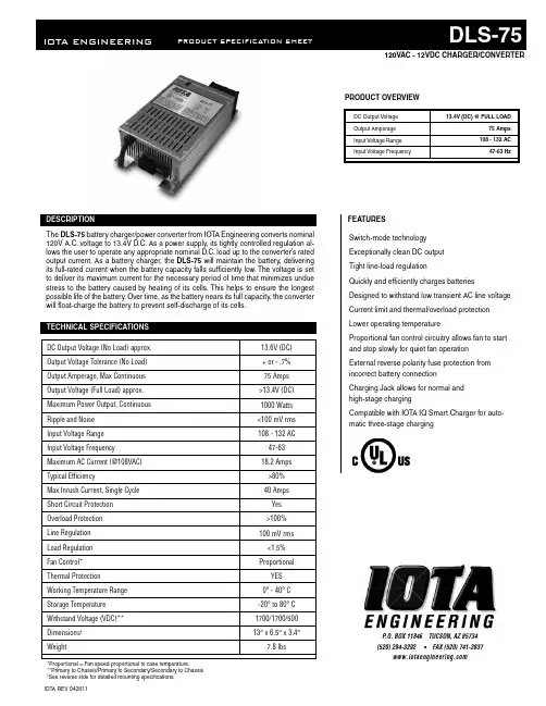
IOTA REV 042811P .O. BOX 11846 TUCSON, AZ 85734 (520) 294-3292 • FAX (520) 741-2837FEATURESPRODUCT OVERVIEWSwitch-mode technology Exceptionally clean DC output Tight line-load regulationQuickly and efficiently charges batteriesDesigned to withstand low transient AC line voltage Current limit and thermal/overload protection Lower operating temperatureProportional fan control circuitry allows fan to start and stop slowly for quiet fan operation External reverse polarity fuse protection from incorrect battery connectionCharging Jack allows for normal and high-stage chargingCompatible with IOT A IQ Smart Charger for auto-matic three-stage chargingDC Output Voltage Output Amperage Input Voltage Range Input Voltage Frequency13.4V (DC) @ FULL LOAD75 Amps 108 - 132 AC47-63 HzDC Output Voltage (No Load) approx.Output Voltage Tolerance (No Load)Output Amperage, Max Continuous Output Voltage (Full Load) approx.Maximum Power Output, Continuous Ripple and Noise Input Voltage Range Input Voltage Frequency Maximum AC Current (@108VAC)Typical EfficiencyMax Inrush Current, Single Cycle Short Circuit Protection Overload Protection Line Regulation Load Regulation Fan Control*Thermal Protection Working Temperature Range Storage Temperature Withstand Voltage (VDC)**Dimensions † Weight13.6V (DC)+ or - .7%75 Amps >13.4V (DC)1000 Watts <100 mV rms 108 - 132 AC 47-6318.2 Amps >80%40 AmpsYes >100%100 mV rms <1.5%ProportionalYES 0° - 40° C -20° to 80° C 1700/1700/50013″ x 6.5″ x 3.4″7.8 lbsThe DLS-75 battery charger/power converter from IOTA Engineering converts nominal120V A.C. voltage to 13.4V D.C. As a power supply, its tightly controlled regulation al-lows the user to operate any appropriate nominal D.C. load up to the converter’s rated output current. As a battery charger, the DLS-75 will maintain the battery, delivering its full-rated current when the battery capacity falls sufficiently low. The voltage is set to deliver its maximum current for the necessary period of time that minimizes undue stress to the battery caused by heating of its cells. This helps to ensure the longest possible life of the battery. Over time, as the battery nears its full capacity, the converter will float-charge the battery to prevent self-discharge of its cells. 120VAC - 12VDC CHARGER/CONVERTER*Proportional = Fan speed proportional to case temperature.**Primary to Chassis/Primary to Secondary/Secondary to Chassis †See reverse side for detailed mounting specifications.The DLS Series Battery Charger/Power Converter is warranted from defects in ma-terials or workmanship for two years from date of retail purchase, and limits the rem-edies to repair or replacement. This warranty is valid only in the continental United States and Canada. For complete warranty details, contact Customer Service or visit .IOT A REV 042811WARRANTYDLS-75BATTERY CHARGER/POWER CONVERTERMOUNTING FOOTPRINTDisconnect the positive side of the battery before installation. Connect the positive (red) and negative (black) terminal lugs to battery or load. Always use the proper size wire based on the amperage of the converter and the battery. When connecting to a battery, a breaker should be installed within 18″ of the battery, connecting the battery positive to the line side of the breaker, and the DLS to the load side. Connect “Chassis Bonding Lug” on the DLS to vehicle chassis or other grounding source.Plug the DLS A.C. input cord into a 120 volt 3-wire grounded source. See chart for maximum current draw and required input voltages. For complete installation guidelines, refer to the installation manual.IOTA ENGINEERING PO BOX 11846 TUCSON, AZ 85734 TEL: 1-800-866-IOTA (4682) FAX: (520) 741-2837 WEB: DUAL VOLTAGE JACKThe DLS-75 is equipped with a Dual Voltage Jack and Dual Voltage Plug that allows manual switching from a long-term float voltage of 13.6vdc to 14.2vdc. When the Dual Voltage Plug is in-serted in the jack, the voltage increases to 14.2vdc for occasional fast charging. When the plug is removed, the voltage drops to 13.6vdc to reduce battery water loss.The Dual Voltage Jack also allows for easy installation of an external IQ4 Smart Charger for automatic 3-stage charging (optional). If the unit is equipped with an internal IQ4 smart charger, two-step charging is not needed and the Dual Voltage Jack is disabled. For details on 3-stage charging voltages, refer。
高德威产品手册解决方案HUA system office room 【HUA16H-TTMS2A-HUAS8Q8-HUAH1688】终端服务器:终端服务器×11.6.1标清独立处理单元车牌识别方案1.6.1.1 主要特性独立工作的处理单元,独立处理图像采集与处理,通过以太网或串口接口方式与计算机通讯,独立性强,系统性能稳定可靠。
1.6.1.2 订货型号GW-PR-9902T- VPD ⅡAD1.6.1.3 硬件接口1. 通信:LAN 网络接口,RS232串行接口;2. 触发:车辆检测器输出存在式、进入脉冲式—转换继电器触点;3. 电源:AC220V 。
1.6.1.4 技术参数抓拍图像及号牌识别时间: ≤200毫秒; 号牌定位率: ≥98%;整牌识别率: ≥90%(包括汉字、字母、数字、颜色); 允许车辆行驶速度: 0-160公里/小时;抓拍单立柱单牌照定位用闪光灯 智能补光闪光灯万向头抓拍图像格式:720×288,JPEG存储图像格式: 360×288,JPEG;≤40K号牌彩色图像:压缩后≤500字节号牌二值化图像:尺寸(长×宽): 112×20像素,≤280字节;号牌信息内容:颜色、汉字、字母、数字,长度:≤14字节;平均修复时间:MTTR≤30分钟;平均无故障连续运行时间: MTBF≥20000小时;专用摄像机的快门速度可达: 1/500000秒;智能补光灯寿命:≥100万次;设备接口:10/100M以太网口,RS232串口;支持平台: WINDOWS 98/2000/XP;通信协议:GW-PR-9902T牌照识别器通讯接口动态链接库;电源适应性: AC220V±44V,50Hz±2Hz;功耗: <50W;工作温度: -10℃— +85℃(处理单元),-40℃— +85℃(采集单元);相对湿度: < 95%,无凝结;防护等级: IP66;处理单元尺寸:180mm(长)×115mm(宽)×48mm(高);抓拍单元尺寸:总高度:1300mm或780mm;防护罩(长×宽×高):500㎜×168㎜×148㎜;立柱尺寸:高度:1050mm或525mm;底座:φ234mm。
目录1 AutoPlant软件简介 (2)2 AutoPlant软件二次开发成果 (3)2.1 元件库 (3)2.2 等级库 (4)2.3 单管图配置 (4)2.4 报表格式RPT文件 (4)2.5 非标设备及管件的定制成果 (4)3 AutoPlant软件二次开发成果的使用 (4)3.1 元件库的使用 (4)3.2 等级库的使用 (5)3.3 单管图配置的修改 (6)3.4 报表格式RPT文件的配置 (7)3.5 非标设备及管件的使用 (10)4 问题及建议 (13)AutoPlant数据库使用简明手册1A UTO P LANT软件简介AutoPlant产品由美国BENTLEY公司(原属美国REBIS公司,为AUTOCAD 平台全球第一大开发商)出品,运行在AutoCAD2000-2008平台上的工厂设计软件。
该软件可在真实的三维环境下进行设计,模型建立过程智能性强,符合设计人员思维习惯。
建模完成后,可对模型进行碰撞检查和实时漫游,最大程度地减少设计中的错、漏、碰、缺现象,并可迅速地生成平、立、剖面图,全自动地生成单管图和精确的材料统计表等设计资料。
AutoPlant工厂设计软件的产品,主要包括以下程序模块:1)P&ID智能工艺流程设计系统工艺软件包为用户制作智能工艺图表提供了一套独特的工具。
工艺软件包中的模块均应用工业的标准技术,比如:AutoCAD、 MS Office以及ODBC的数据库驱动。
应用该软件包,用户可在很短的时间内就可以设计方案,而不需要研究大量的图纸以及三维模型。
2)Data Manager工艺数据管理器外部资料库的管理系统,具有资料输入、编辑及报表生成功能。
这种转换工具减少了项目的启动时间,提供了更准确的项目数据和便于维护的环境。
3)Piping三维配管模块Piping作为三维工厂设计系列中最重要的模块,运行在AutoCAD图形平台上,采用最新的Object-ARX面向对象技术,全面支持Visual BASIC、C++以及Visual LISP技术。
- ii -版权申明本手册内容,包括文字、图表、标志、标识、商标、产品型号、软件程序、版面设计等,均受《中华人民共和国著作权法》、《中华人民共和国商标法》、《中华人民共和国专利法》及与之适用的国际公约中有关著作权、商标权、专利权或其他财产所有权法律的保护,为北京和利时机器控制技术有限公司专属所有或持有。
本手册仅供商业用户阅读、查询,在未得到和利时公司特别授权的情况下,无论出于何种原因和目的,均不得用任何电子或机械方法,以任何形式复制和传递本手册的内容。
否则本公司将依法追究法律责任。
我们已核对本手册中的内容、图表与所述硬件设备相符,但误差难以避免,并不能保证完全一致,还恳请广大用户批评指正。
同时,我们会定期对手册的内容、图表进行检查、修改和维护,恕不另行通知。
本手册的说明、图表、简单程序及应用实例完全出于举例说明的目的,我们对其都进行了测试,但因为软件版本的更新和各种应用有许多未知的变化和要求,我们不承担根据本手册或本手册中的实例而构成的实际应用产生的责任。
和利时公司保留全部权利。
2008 Copyright HollysysHOLLiAS 、HollySys 、和利时、 的字样和徽标均为北京和利时机器控制技术有限公司的商标或注册商标。
Microsoft 、Windows 和WindowsNT 是微软公司在美国和/或其他国家分支机构的商标或注册商标。
手册中涉及到的其他商标或注册商标属于他们各自的拥有者。
本手册适用于Autothink V3.1.1B1版本软件使用重要信息在本手册中,使用以下标识明确相应信息:用来帮助用户深入理解系统的技术问题。
用来明确使用系统的相关习惯或安全注意事项。
用来明确使用系统的相关限制行为或安全注意事项。
目录第1章AutoThink软件概述 11.1功能概述 (1)1.2软件安装 (2)1.3软件卸载 (7)第2章AutoThink软件快速入门 92.1AutoThink编程的简要流程 (9)2.2硬件配置 (17)2.3示例说明 (17)2.4程序编写 (18)2.5编译程序 (22)2.6通讯设置 (23)2.7下装程序 (24)2.8在线调试 (25)2.9仿真调试 (27)第3章AutoThink软件的编程环境 283.1软件启动 (28)3.2界面概述 (30)3.3标题栏 (32)3.4菜单栏 (32)3.5工具栏 (33)3.6工程管理 (35)3.7工作区域 (36)3.8库管理器窗口 (44)3.9设备库窗口 (56)3.10状态栏 (59)第4章AutoThink软件的编程基础 604.1数据 (60)4.1.1数据的含义 (60)4.1.2数据的存储区 (61)4.1.3数据的存储格式和地址 (66)4.1.4数据的类型 (67)4.2变量 (74)4.2.1变量的类型划分 (74)4.2.2变量的声明规范 (76)4.2.3变量的声明格式 (78)4.2.4变量的声明方法 (83)4.2.5变量的访问 (87)4.3指令 (88)4.3.1IEC运算指令 (88)4.3.2库指令 (90)4.3.3指针运算 (91)第5章AutoThink软件的编程语言 955.1AutoThink软件的梯形图编程 (95)5.1.1LD编辑器 (95)5.1.2 LD元素 (96)5.1.3 LD操作说明 (97)5.1.4 LD编程举例 (124)5.2AutoThink软件的结构化文本编程 (128)5.2.1ST编辑器 (128)5.2.2ST操作符 (130)5.2.3ST语句 (130)5.2.4ST编程举例 (132)5.3AutoThink软件的连续功能图编程 (134)5.3.1CFC编辑器 (134)5.3.2CFC元件 (134)5.3.3CFC操作说明 (137)5.3.4CFC编程举例 (151)第6章AutoThink软件的程序组织单元 1546.1程序组织单元概述 (154)6.1.1程序组织单元的类型 (154)6.1.2程序组织单元的调用关系 (155)6.2程序组织单元的创建 (156)6.3程序组织单元的操作 (160)6.3.1程序块的操作 (160)6.3.2程序组织单元的操作 (161)6.4程序组织单元的调用 (164)6.4.1程序调用功能块 (164)6.4.2程序调用程序 (176)6.4.3程序调用函数 (180)6.5程序组织单元的触发 (184)第7章硬件配置 1877.1硬件配置文件 (187)7.2硬件配置窗口 (187)7.3硬件配置方式 (190)7.3.1配置CPU模块 (190)7.3.2配置IO模块 (192)7.3.3模块信息 (193)7.3.4通道信息 (195)7.4平台切换功能 (196)7.4.1平台切换的触发方式 (196)7.4.2平台切换后工程的变化 (199)第8章编译和调试 2008.1编译 (200)8.1.1编译目的 (200)8.1.2编译结果 (200)8.2下装 (201)8.2.1通讯设置 (201)8.2.2下装步骤 (202)8.2.3异常处理 (203)8.3调试 (203)第9章高级功能 2089.1工程管理 (208)9.2打印功能 (230)9.3工程编辑 (232)9.4工具向导 (249)第10章网络与通讯 27010.1数据通讯技术简介 (270)10.1.1串行通信接口标准 (270)10.2LE系列PLC串口通讯技术 (272)10.2.1Modbus RTU概述 (272)10.2.2Modbus RTU通讯功能 (272)10.2.3Modbus RTU通讯举例(LE作从站) (273)10.2.4Modbus RTU通讯举例(LE作主站) (274)10.2.5串口自由协议通讯举例 (281)10.3以太网通讯 (284)10.3.1Modbus TCP通讯功能 (284)10.3.2Modbus TCP通讯举例 (284)10.4附:LE扩展模块诊断信息 (285)10.4.1.数字量扩展模块诊断信息 (285)10.4.2.模拟量扩展模块诊断信息 (285)10.4.2.1 模拟量输入模块 (285)10.4.2.2 模拟量输出模块 (286)10.4.2.3 模拟量混合模块 (287)10.4.2.4 热电偶模块 (287)10.4.2.5 热电阻模块 (288)10.4.2.6 DP通讯模块 (288)10.4.2.7 以太网通讯模块 (289)10.4.2.8 GPRS通讯模块 (289)第1章 AutoThink软件概述本章简要介绍AutoThink软件的基本功能,并说明AutoThink软件的安装和卸载方法。
提供动力。
探索今天的伊顿。
我们提供:• 方案• • •动及动力总成解决方案马达控制设备命令和控制设备终端保护产品自动化和驱动产品134MOEM 市场综合样本目录2马达和线路控制设备伊顿拥有超过百年的接触器研发和制造经验,为用户提供至3185A 的线路控制解决方案,并提供不同系列的产品以满足用户的的多种要求Xstart 系列接触器:全球化的产品,提供包括UL 在内的主流认证,最高达3185安培(AC-1)的产品:• 独特的CT 型励磁机构,功耗更小;• 115A 以上集成电子线路板,降低功耗同时工作电压幅度更宽;• 580A 以上真空灭弧,应对严苛使用环境,业界最长预期寿命;• 提供本地化的XstartC 系列(认证情况请咨询当地销售办事处)。
D 系列接触器:本地化的产品,提供最高到500A 的高效控制和保护方案,应用于泵、风机、压缩机等场合,提供功能全面的辅助触点和宽幅的控制线圈电压选项。
• 齐全的线圈控制电压,185A 以上更提供交直流通用产品;• 全系列内置辅助触点• 百万次以上电气寿命• 使用温度-20 °C ~ +55 °CE 系列接触器:全球最小的电磁接触器之一,有效地利用空间,可靠性增强,材料使用更高效。
E 系列接触器额定值可至AC-3, 95A@400V ,最高工作电压高达660V ,体积小巧,却提供强大的性能。
• 百万次以上电气寿命• 690V 绝缘额定值• 最多可加装6个辅助触点模块• 常用交流控制电压及直流24VDC 线圈1马达控制设备目录电机控制产品 xStart C 接触器式继电器DILA..C 接触器DILM..C 过载继电器ZB..C电动机保护断路器PKZMC 电机控制产品 D 系列接触器 XTCD 热过载继电器 XTOD 电气行业解决方案 Eline 控制继电器 XTRG 接触器 XTCG热过载继电器 XTOD/XTOG电机控制产品 xStart C电机控制产品 D 系列电气行业解决方案Eline1接触器式继电器DILA..C目录系统概览 . . . . . . . . . . . . . . . . . . . . . . . . . . . . . . . . . . . . . . . . . . . . . . . . . . . . . . . . . . . . . . . . . . . . .本体DILA..C . . . . . . . . . . . . . . . . . . . . . . . . . . . . . . . . . . . . . . . . . . . . . . . . . . . . . . . . . . . . . . . . . .辅助触点模块 . . . . . . . . . . . . . . . . . . . . . . . . . . . . . . . . . . . . . . . . . . . . . . . . . . . . . . . . . . . . . . . .附件 . . . . . . . . . . . . . . . . . . . . . . . . . . . . . . . . . . . . . . . . . . . . . . . . . . . . . . . . . . . . . . . . . . . . . . . . .操作电压 . . . . . . . . . . . . . . . . . . . . . . . . . . . . . . . . . . . . . . . . . . . . . . . . . . . . . . . . . . . . . . . . . . . . .特性曲线,触点行程图 . . . . . . . . . . . . . . . . . . . . . . . . . . . . . . . . . . . . . . . . . . . . . . . . . . . . . . . .技术数据 . . . . . . . . . . . . . . . . . . . . . . . . . . . . . . . . . . . . . . . . . . . . . . . . . . . . . . . . . . . . . . . . . . . . .尺寸 . . . . . . . . . . . . . . . . . . . . . . . . . . . . . . . . . . . . . . . . . . . . . . . . . . . . . . . . . . . . . . . . . . . . . . . . .4极触点多种组合约定发热电流(I th )16A 交流与直流操作的产品尺寸相同直流操作的产品内置浪涌抑制器••••接触器式继电器DILA..C35791112131911接触器式继电器DILA..C说明121接触器式继电器DILA..C系统概览31接触器式继电器DILA..C系统概览4系统概览本体AC 或DC 操作电磁系统AC DC 可以扩展到8对触点反向互锁触点模块化系统螺钉连接和卡装手指接触防护螺钉端子第5页起抑制电路用于直流操作接触器式继电器的保护电路(所有直流型均内置)用于交流操作接触器式继电器的保护电路第32页起辅助触点模块23, 42或4极反向互锁触点第7页起124 – 400V, 50, 60, 50/60 Hz0.8 – 1.1 × U c 24 VA/3.4 VA 24 – 220 V DC0.8 – 1.1 × U c 于24 V :0.7 – 1.3 × U c 无附加辅助触点模块环境温度+40°C 3W/3W1接触器式继电器DILA..C本体5接线方式:螺钉端子触点N/O = 常开N/C = 常闭带反向互锁触点的本体额定工作电流AC – 15220 V230 V240 VI e约定发热电流,敞开,于60°CI th代码序号触点序号380 V400 V415 VI e1本体DILAC-XHI(V)...DILAC-XHI(V)...DILAC-XHI(V)...DILA-40C(220-230V50Hz)114842DILA-31C(220-230V50Hz)114852DILA-22C(220-230V50Hz)114862DILA-40C(24VDC)114847DILA-31C(24VDC)114857DILA-22C(24VDC)1148671件1件1件可以组合辅助触点模块标准包装说明AC 操作型号订货号操作电压220-230V50HzDC 操作型号订货号操作电压24VDC附件1 抑制器2 辅助触点模块操作电压页数32711触点编号,符合EN 50011线圈端子标记,符合EN 50005直流操作的接触器式继电器具有一个内置的保护电路。