五轴版PM智能深孔钻教材2017
- 格式:docx
- 大小:5.55 MB
- 文档页数:29
| ROMI DCM 620-5X | ROMI DCM 620-5FINNOVACIÓNMecanizado y Fabricación aditiva en un solo equipoCOMPENSACIÓNTÉRMICAA través de los sensores instalados en lugares estratégicos del equipo, algoritmos matemáticos hacen la corrección de la posición de los ejes en tiempo real. De esta forma se obtienen resultados dimensionales estables, durante largos periodos de trabajo.ŸCNC Siemens 840D sl con pantallacolorida 19" (ROMI DCM 620-5X)ŸCNC Siemens 828D con pantallacolorida 15.6" (ROMI DCM 620-5F)ŸCobertura completa contra virutas ysalpicaduras ŸCompensación térmicaŸDocumentación completa del producto ROMIŸDos ejes rotatorios con encoder directo(B y C) (ROMI DCM 620-5X)ŸGuía linear de rodillos en los ejes X, Y, Z Notas:(A) Seleccionar obligatoriamente (B) Venta obligatoria del opcional "Cierre de la zona de mecanizado"(C) Se recomienda la venta del accesorio "Sistema de extrator de niebla".(D) Venta obligatoria del accessorio "Sistema para medición/inspección de piezas"ŸInstalación eléctrica disponible para la siguiente tensión/frecuencias: 380VCA / 50-60Hz ŸJuego de llaves principales para operación de la máquina ŸJuego de tornillos y tuercas de nivelación ŸJunta rotativa para refrigeración interna ŸEquipo de iluminación fluorescente selado ŸCojinete para apoyo de la mesa ŸPanel de operación auxiliar manual(handwheel), con funciones de manivela y JOG para ejes ŸPainel elétrico com climatização centrífuga e pressão positiva ŸPistola de lavado (Wash gun)ŸPuerta principal con traba eléctrica de seguridad ŸSistema de lubricación centralizada ŸSistema de resfriamento do cabeçote ŸSistema de refrigeración de corte con bomba de 5bar y tanque (capacidad de 240 litros) ŸSistemas hidráulico y neumático completos ŸSistema neumático para limpieza del cone del husillo ŸSistema de lavado del área de trabajo ŸSistema de limpieza de la base ŸSistema hidráulico para extracción de la herramienta ŸCambiador de herramientas con brazo automático (ATC), con capacidad para 30 herramientas (BT/BBT 40) ŸPintura estándar: Esmalte Epoxy Texturizado Azul Munsell 10B-3/4 e Tinta Epoxy Texturizada Gris Claro RAL 7035ŸTransportador de virutas longitudinalde cinta articulada metálica (TCE) (A)ŸTransportador de virutas longitudinal de cinta de arrastre (TCA) (A)ŸAire acondicionado para armario eléctrico ŸAutotransformador para red 200 hasta 250VAC / 50-60Hz o red 360 hasta 480VAC / 50-60Hz ŸBomba de alta presión para refrigeración por el centro del husillo7, 20 o 70 bar (B)ŸApagado automático de la máquina luego del fin del turno (auto power off) ŸEsfera de Calibración (D)ŸCierre de la zona de mecanizado (C) ŸInterfaz para diagnóstico remoto por cable ŸPintura especial ŸSeparador de aceite / refrigerante (Oil skimmer)ŸSistema de extractor de niebla (B)ŸSistema para medición / inspección de piezas con palpador RMP60ŸSistema para seteado de herramientas con láser Renishaw NC4ŸSistema de limpieza neumática durante el mecanizado ŸTransductor linear de posición (regla optica) eje X/Y/Z ŸJuego adicional de manuales del producto ROMI ŸEncoder para ejes giratorios B y C (ROMI DCM 620-5F) ŸColumna luminosa indicadora de operación (3 colores)Detalle de la Ranura ‘'T''18 H7+0,020 18 H12(Ranura Central) (Otras Ranuras)1,5 x 45° (2x)16+230+201 2 1。
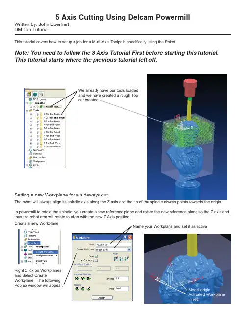
5 Axis Cutting Using Delcam PowermillWritten by: John Eberhart DM Lab TutorialThis tutorial covers how to setup a job for a Multi-Axis Toolpath speci fi cally using the Robot.Note: You need to follow the 3 Axis Tutorial First before starting this tutorial.This tutorial starts where the previous tutorial left off.We already have our tools loaded and we have created a rough Top cut created.Setting a new Workplane for a sideways cutThe robot will always align its spindle axis along the Z axis and the tip of the spindle always points towards the origin.In powermill to rotate the spindle, you create a new reference plane and rotate the new reference plane so the Z axis and thus the robot arm will rotate to align with the new Z Axis position.Create a new WorkplaneRight Click on Workplanes and Select CreateWorkplane. The followingPop up window will appear.Name your Workplane and set it as activeAdjusting the Workplane using the pop up window.Using the pop up window, you can move theposition and Rotation of the active workplaneby inputting a value in millimeters and clickingon the appropriate translation or rotation button.Using the input Box, I rotated the Workplane sothe Z axis, and thus the tool is pointing towardsthe back. I also have the workplane’s X and Yaxis so they are on the surface and to the backof the box.If these axes were in the middle the tool wouldstart at the middle of your piece.Note: If the block is moving with the tool, thenyou forgot to lock down the block. To do thisopen the block settings and click the lock button.(See the 3 Axis tutorial on how to do this)Perform a Rough Cut on the back of the piece.Click on the machining strategies button, and using the same settings in the 3 Axis tutorial, I generated a rough cut on the back of the model. In addition, I limited the depth of the cut using the Limit Toolpath method. To limit the toolpath, right click on the toolpath, and select Edit>LimitCompleted ToolpathLimited Toolpath.Note: remember to reset your safe Z heights beforecalculating the tool path.Roughing the Front of the Piece:To rough the front of the model, we are going to create a new Workplane, then move and rotate the workplane so that the tool is pointing to the front of the model. Make sure none of the workplanes you already created are active. if they are, right click and uncheck activate.New Workplane (Rough Front)Active the new workplane Using the Move and RotateControls Position the new workplane to the front of the model, and make sure the tool is pointing towards the model.position in RedNote: remember to reset your safe Z heights beforecalculating the tool path.Completed Toolpath Limited Toolpath.Setting up Tool moves to control the Robot Arm from the Back to the Front:Robots by de fi nitions are very stupid. Currently if we were to cut this job, the robot would fi nish the back, and then take the shortest path to the front of the model and start cutting the front. That means the robot’s arm and spindle would move through the part destroying it in the process.If you simulate the toolpaths, there will be a hole in the middle of the model where the bit passed.Hole in model when bit passed through the model moving from the back to the frontCut in model when bit moved from top to backIn order to control how the arm moves around your model, you need to create a series of workplanes and thoseworkplanes are then placed in the correct move order in the NC program.Crate a new Workplane. Right click onWorkplanes and right click and select CreateWorkplane.I called this workplane “Toolmove 1” and made it active.Using my Move and Rotate controls, I positioned the workplane to the top front and left side of the model.Note: DO NOT create a workplane from an existing workplane, AlWAYS deactive any workplanes fi rst. If you create a workplane from an existing workplane, the robot will not follow the connecting move correctly and could result in hitting your workpiece, the fl oor, or the table.Repeat the process and Create another toolmove workplane for the front of the modelTool Move 1Tool Move 2Settings for tool move2 reference planeLoading the ‘tool Move” reference Planes into the NC program:Drag and drop theworkplanes in to the NC program in the proper order.In the Powermill window you will see blue connection lines stitching the toolpaths and workplanes together. The Arrows indicate the direction of the connection moves.Tool Move 1Tool Move 2Activate the NC program by right clicking and select activate.Simulate your job, verify that you have no collisions and post your Job!5 Axis Finish CutsPowermill Allows you to perform a number of different types of fi nish cuts. To perform a fi nish type cut, click on the toolpath strategies Icon and select a fi nish cut from the library of cuts.Click the Finishing tab for thefi nishing librarySelect a Finishing Strategy and apreview of how the cut will workappearsMost of the Toolpath Strategiesare for very specifi c uses. Youshould spend some time goingthrough the various types offi nish strategies.Raster Finishing is most like thefi nishing strategy in Madcam orSurfacm.Corner Pencil Finishing isthe same as the Pencil cut inmadcam.Applying a 5 Axis Finish Cut.Activate the front rough Workplane and click on the toolpath strategies button.Note: remember to reset your safe Z heights beforecalculating the tool path.The Raster Finishing settings window appears.Choose the bit you want to use. In this case I am using a 1/2” dia ball nosed bit.Leave our tolerance at 0.1Your offset thickness should be at 0.0Stepover will be determined by the fi nish quality. Smaller the stepover, the smoother the fi nish, but it takes longer.I recommend you do a stepover of 1-3mmThis sets the lead in and lead out controls we will get into this in more detail.Leave tool axis on vertical for now, we will get into this as well.Name your toolpath (Finish planar)Choose a starting corner.You can adjust the ordering of the passes. If you are cutting wood, you want to choose one way. If you are cutting foam, both ways is fi ne.Clicking draw and preview will show a rough idea of how the toolpath will look.Previewed ToolpathHit Apply to calculate the toolpathactual cutting moves, blue and red lines arelead in and lead outs. This particular toolpathhas a lot of wasted moves. We can correct thisby adjusting the Lead in and lead out moves.To do this right click on the fi nish planartoolpath, and choose settingsIn powermill, you can pull upa completed toolpath settingswindow and recycle the job,allowing you to adjust thejob.Click on the recycle buttonto reactivate the toolpathsettings.Click on the Leads and Links setting button. The above popup window will appear. Click on the links tab. Under the Short,options, choose Skim. For the Long and default choose Skim.This will make the bit follow along the surface when it ismoving from one cutting line to another. Click the Apply linksButton and then accept.Click Accept again to recalculate the toolpath.Resulting revised Links.Projected Point Full 5 Axis Finishing:Note: remember to reset your safe Z heights beforecalculating the tool path.Click on Toolpath Strategies, then select Projection Plane FinishingSet your toolSet your StepoverSet your Lead in and Lead outs to Skimand on SurfaceClick on draw and Preview Anchor point sets the beginning of the plane Azimuth and Elevations sets the 3D orientation of the plane. Move the sliders and watch the plane rotateDirection sets the direction ofthe projection. You want thedirection arrows on the planeto point toward the model.Pattern direction sets eitherhorizontal or vertical passesHeight and Width sets thesize of the projected plane. Previewed model. The plane with the horizontal linesis the projected plane. The stepover sets the densityof the horizontal lines.Click Apply to calculate the projected plane.This toolpath is fi ne, but the bit will always stay vertical off of the piece. With a 5 Axis mill you can tip the bit back and forth to allow you to get into tight areas. To do this recycle the Projected Plane Toolpath.With the toolpath recycled, click on the Tool Axis Icon. At the popup window .Choose Toward Point. This willpoint the axis of the tool toward asingle point.That point is specifi ed by XY andZ coordinates.If you view your model in aorthogonal view, you can geta reading on the XY and Zcoordinates.Check Draw tool Axis and AutoCollision AvoidanceThen Click the CollisionAvoidance Tab.You can specify Special tool axistilts in this drop downYou can set a clearance distancefrom your shank and HolderClick Accept when done andrecalculate your toolpath.The tool is leaning as the Bit Cuts the surface.。
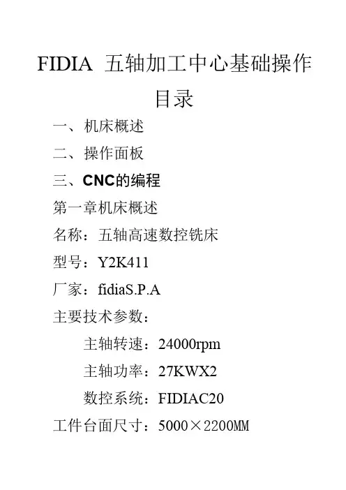
FIDIA五轴加工中心基础操作目录一、机床概述二、操作面板三、CNC的编程第一章机床概述名称:五轴高速数控铣床型号:Y2K411厂家:fidiaS.P.A主要技术参数:主轴转速:24000rpm主轴功率:27KWX2数控系统:FIDIAC20工件台面尺寸:5000×2200MM工作台最大载重:20000KG实际加工尺寸:X轴4200mm、Y轴110mm、Z轴1000mm A轴(主机床)95°~-110°(附机床)-95°~110°C轴±180°第二章操作面板一、启动和关闭1、启动:打开主机电源后进入windows见面,点击“开始”选择“程序”再选择FidiaUtility文件,然后点击Userinterface进入用户界面。
2、关闭:从File菜单上选择关闭Exit,关闭CNC的命令页面(其它相关的系统界面先关闭,主界面才会关闭)。
最后关闭电脑再关闭总电源。
二、应用窗口界面在CNC命令界面被执行后,在显示器上显示出一个窗口,它占有了整个桌面,其组成如下:A菜单条B显示和工作区域陈列,取决于上下文,位置值,对话窗口,图,目录以及使用者输入值或其它数据的参数或命令窗口C一个按时间顺序显示CNC信息的盒子D垂向软件键条E横向软件键条F日期和时刻1、横向软件键条:RES T·RESTCNC:机床恢复ZERO·RQ:各轴自动顺序回机床零点(Z、A、C、Y、X)·X、Y、Z、A、C:单独轴选择回零点SETCOMMAND:设置命令屏幕显示:F进给S转速UNIT公/英制单位RCTP(五轴连动)OF/ONTOOLCOORD刀具坐标轴OF/ONROTO当前原点坐标的旋转角度SETCOMMAND·SETORIGIN:设置加工原点坐标(1-10个)机床的原点为零号坐标系,是不能更改的。
·SAVEORIGIN:记录坐标数据·RSETORIGIN:恢复坐标数据·CQAHADWH:手轮调节偏移量OF/ONSAVERESTORE:SAVE记录·TOOLTABLE刀具表RESTORE恢复·TOOLTABLE刀具表2、竖向软件键条:CNC环境·PARCNC(参数)·SWITCH使能/禁止阅读被编程的功能·AXIS各轴开关·FSC各轴镜像·MDCNC选择零件程序的执行模式·CQA各轴偏移量·ROTANG·ROTANG以坐标系旋转·ROTCEN以中心旋转·PROGLIM程序限位·AXISLIM轴限位·SAFETYLIM安全限位·TOOLTABLE:刀具表(0号为当前主轴无刀,1-41号为可自动/手动换刀,42号为测头专用刀位,43-100号为自定义刀号)Type1–圆柱平刀具Type2–圆柱圆角刀具Type3–球状刀具Type4–球状刀具,带一个圆周嵌入件Type5–圆柱圆角刀具,带两个圆周嵌入件Type6–圆柱圆角刀具,带两个方嵌入件Type7–锥状刀具,带平刀尖Type8–锥状刀具,带圆角刀尖Type9–镗刀Type10–带刀尖的刀具类型1圆柱体刀具类型2复合型刀具类型3球头刀具类型4带一个嵌入件的球头刀具类型5带两个圆形嵌入件的复合型刀具类型6带方形嵌入件的复合型刀具类型7带平端头的锥体刀具类型8带复合型端头的锥体刀具CNC环境·EXECUTE执行窗口·EXECUTEFILE执行一个零件程序。
五轴加工中心培训课程五轴加工中心培训课程多轴(四、五轴)加工技术培训课程是三轴数控加工技术课程的补充和提高,符合国家职业标准对于高级工和技师的要求.二、培训目标通过学习数控多轴(四、五轴)加工技术,使学员能够了解多轴加工的基础知识,会操作五轴机床.在专业技能上达到完成零件加工工艺制定、编制多轴加工程序、利用多轴仿真软件实现产品加工的安全保证、能使用多轴(四、五轴)机床加工复杂零件的能力。
三、培训时间:2个月四、课程内容:(一)软件部分1、UG NX多轴编程2、MasterCAM多轴编程(二)机床部分1、四、五轴加工介绍,机床结构与运动关系,各种机床的加工特点,运用场合及优势;2、定轴加工(3+2)在模具及零件加工中的应用;3、NX软件刀具轴的控制方法;4、四、五轴实例分析及案例讲解;5、机床仿真;6、(可变轴铣、外形轮廓铣);(1)多种刀轴设置(2)插补刀轴设置(3)垂直于部件17、四、五轴联动工件铣削;18、四、五轴机床的仿真加工;19、独立完成加工与编程。
课程特点:(1)同时学习到四轴与五轴加工中心的编程与加工技术,课程更超值,学习效率更高;(2)采用流行的数控编程软件,Mastercam、UG、PM等,方便已有软件基础的学员进行学习;多轴(五轴)加工培训大纲一、培训课程性质多轴(五轴)加工是数控加工技巧中很重要的一个部分,该项技巧在航空航天、汽车、船舶、医疗、模具、轻工、高精密仪器等制作领域得到广泛利用。
随着对产品的要求千锤百炼:产品的结构形势日趋复杂,生产效率不断前进,数控机床的更新换代,控制数控多轴加工技巧已经突显出它的重要作用。
然由于受到机床硬件前提和师资力量不足的限制,职业院校开设的数控加工课程内容多仅限于三轴加工、理论性比较强,很少涉及数控多轴加工的内容,实战内容比较少,所以使得很多学生不得不在参加工作以后才接触到多轴设备和实战经验。
从而影响了他们的工作效率和企业的生产定单.为了满足企业加工需求,在数控教学、培训中开设数控多轴(五轴)加工技巧课程已是迫在眉睫。
五轴深孔钻安全操作及保养规程前言五轴深孔钻是一种用于加工深孔的机床。
在使用五轴深孔钻时,应注意安全操作和正确保养,以确保操作安全和延长设备的使用寿命。
安全操作规程1. 操作前必须进行检查在操作五轴深孔钻前,必须进行以下检查:1.检查设备连接电源和气源是否正常。
2.检查机床外观是否完好无损,如有影响安全的故障应及时排除。
3.检查工作台、工件、刀具等是否固定良好。
4.检查紧急停车按钮是否正常。
如出现故障应立即通知维修人员进行处理。
2. 操作中注意安全在操作五轴深孔钻时,应注意以下安全事项:1.操作人员必须经过专业培训和授权,了解机床的工作原理和操作规程。
2.在操作机床时,应穿戴符合标准的工作服、防护鞋和耳塞等安全防护装备。
3.禁止在机床悬挂或放置禁止物品,如电缆、工具等。
4.机床门必须保持关闭状态,避免操作人员靠近。
3. 发现问题及时处理在机床操作中如果发现以下问题,应及时停车处理:1.机床出现异常声响、振动等情况。
2.刀具或工件固定不良。
3.刃具损坏或失效。
4.系统故障、液压油温过高等异常情况。
4. 安全操作的注意事项在使用五轴深孔钻时还需要注意以下事项:1.禁止在操作过程中手动调整刀具或工件,以免造成伤害。
2.禁止长时间单人操作,应定时交替换班。
3.不得捏住工件表面,应使用合适的夹具固定工件。
4.操作时应注意清除加工区域内异物,并做到及时清理切屑和边角料。
保养规程定期保养五轴深孔钻需要进行定期保养以确保机床的正常运行。
定期保养包括:1.外观清洁:每周对机床的外观进行一次清洗,并对油污和灰尘进行清除。
2.液压系统:每1000小时换一次液压油,并定时清洗油箱。
3.电器系统:每周对电路进行检查,确保电器元件连接牢固。
4.空气冷却系统:每月对空气过滤器进行清洗。
日常保养除定期保养外,机床每日还需要进行日常保养:1.使用适量液压油和润滑剂,以确保机床的顺畅运转。
2.加工过程中定时清理切屑和边角料,以避免对刀具和加工质量的影响。
PowerMILL 5轴加工教材内容提要1. 简介2. 5轴加工选项3. 5轴笔式精加工和清角精加工4. 5轴轮廓加工5. 5轴SWARF 加工6. 径向和轴向余量7. 刀具路径间的刀具移动控制8. 3 + 2 轴加工和钻孔9. PowerSHAPE 在5轴加工中的应用10. 附录简介5轴加工时,床头或工作台除沿三维坐标系做线性移动外也同时做旋转移动。
PowerMILL提供了多个有效的刀具定位方法。
5轴加工可通过一次装夹加工完毕使用3轴加工需多次装夹才能加工的零件。
使用5轴控制器可重新定位刀具,以加工沿Z轴无法直接加工的陡峭表面或是底切区域。
5轴加工时,必须确保选取了合适的切入切出和连接及三维限界,并仔细检查可能导致过切的区域,确保刀具路径无过切。
所有产生的刀具路径在运用于加工前,请确保其已进行过计算机仿真模拟加工检查。
5轴加工选项PowerMILL刀轴的缺省设置为供3轴加工使用的垂直选项。
5轴加工的刀轴定位可通过点击主工具栏或是精加工表格刀轴域(下图左图所示)中的图标来进行。
前倾/侧倾前倾角为刀具沿刀具路径方向的给定角度;侧倾角为和刀具路径方向垂直方向的给定角度。
如果这两个角度的设置均为零,则刀具方向将为刀具路径的法向。
刀具路径的法向为刀具路径产生过程中将其投影到曲面数据上时的方向。
对参考线精加工而言,此方向始终为垂直的;对投影精加工而言,其方向随局部投影方向的变化而变化。
从目录five_axis/3plus2b_as_5axis 装载模型3plus2b.dgk 。
∙按零件尺寸产生毛坯。
∙定义一直径为15mm 的球头刀(bn15)。
∙输入安全Z高度185 ,开始Z高度180。
∙在刀具开始点表格中,设置方式:固定;位置:绝对并输入坐标值:X-100 Y0 Z190。
∙在精加工表格中选取平面投影选项,在刀轴选项中,将前倾和侧倾角均设置为0。
这将迫使刀具方向和加工策略的投影方向一致。
∙切入切出和连接的设置如下:∙Z高度: ------ 掠过15 下切5∙切入/切出: ------ 垂直圆弧: 角度90 半径6∙连接: ------ 短/长: 刀轴掠过安全: 刀轴安全Z高度。
JDPaint V5.5 多轴加工方法(版本0.01)北京精雕科技有限公司2007.08前言本文档从多轴基本知识、控制系统及控制软件(EN3D)设定及加工、JDPAINT5.5五轴编程模块等方面介绍一些常用的多轴加工技术,用以帮助使用者了解多轴加工操作和设定,减少多轴路径编程时间,改善多轴刀具路径质量。
本文档主要以实例的方式来介绍多轴编程加工,在阅读时可以结合实例来学习,可以达到更好的效果。
不同的人有不同的思路,因此请不要把本文档中介绍的一些技术视为多轴加工的基本原理,多轴加工技术内容相当丰富,不是薄薄一本手册可以覆盖的。
同时需要进行大量的实际加工,从中体会多轴加工的不同之处,灵活运用我们现有的编程功能,才能对五轴加工有一定的领悟。
阅读文档的读者应具备以下几方面的背景知识:1、对三轴精雕机有一定了解;2、具备一些模型的三轴加工经验;3、具备一些三维建模(或者曲面造型)经验者更佳。
第一章绪论在过去模具加工很少使用五轴加工,问题在于多轴机床的价格昂贵及人员培训与技术上的困难,大家皆敬而远之。
近年来因模具交期紧迫及价格压缩,五轴机床标准化产量,价格逐年下降,使五轴加工渐渐的受到模具业重视,多轴机床将是继高速加工机后另一个有效的加工工具。
1.1 五轴加工与三轴加工比较五轴加工与三轴加工比较,有以下几方面的优点:1) 减少工件非加工时间,可以提高加工效率五轴加工的一个主要优点是仅需经过一次装夹即可完成复杂形状零件的加工。
和多次装夹相比,它可极大地提高加工和生产能力,显著缩短产品加工周期及加工成本,并且提高了加工精度。
2) 刀具可以摆到更好的位置来加工曲面五轴加工完成一些三轴加工无法完成的加工,比如有负角的曲面零件加工,刀具可以摆到更好的位置来加工曲面,如图1-1所示。
图1-1 刀具可以摆到更好的位置来加工曲面图1-2 缩短加工时间, 改善表面加工质量3) 可以缩短曲面加工时间,改善曲面表面的加工质量五轴加工可通过将刀具倾斜一定角度,例如用铣刀侧刃进行铣削等,缩短加工时间;另外路径间距相同的情况下,用五轴加工工件表面的残留量要比三轴加工小得多,有利于改善加工曲面的表面光洁度,如图1-2所示。
五轴深孔钻机工作原理
五轴深孔钻机是一种专用于进行深孔钻削的加工设备。
它通过沿垂直轴向深入工件内部进行钻孔,使得工件获得所需的孔径和深度。
工作原理如下:
1. 工件固定:首先将待加工的工件夹紧在工作台上,确保其稳定固定于机床上。
2. 五轴定位:深孔钻机具有五个轴向的定位能力,分别是X 轴、Y轴、Z轴、W轴和B轴。
通过这五个轴的协调运动,钻头可以在三个方向上进行平移和旋转。
3. 主轴旋转:启动主轴电机,使其以高速旋转。
主轴是用来传递动力给钻头的关键部件。
4. 切削液供给:将切削液通过切削液泵送到钻头切削区域,起到冷却和润滑的作用,同时也带走钻孔时产生的废渣。
5. 钻削过程:根据设定的加工程序和参数,通过五轴协调运动,将钻头准确地导引到工件内部,进行钻削。
同时,切削液的喷洒也起到冷却切削点和带走废渣的作用。
6. 完成加工:根据加工要求,通过控制五轴的动作收缩钻头,同时还可以进行镦孔、铰孔等后续加工步骤,最终完成所需的深孔钻削加工。
值得注意的是,五轴深孔钻机具有加工精度高、效率高、灵活性强等优点,广泛应用于汽车行业、航空航天工业、机械加工等领域。
PowerMILL 10 5轴内容章页Day 11. 3+2 轴加工和钻孔 1.1 - 1.302. 定位刀具移动 2.1 - 2.83. 5轴刀轴调整 3.1 - 3.264. 曲面投影精加工 4.1 - 4.145. 5轴参考线精加工 5.1 - 5.126. 镶嵌参考线精加工 6.1 - 6.4Day 27. 5轴 Swarf 加工7.1 - 7.168. 刀轴光顺8.1 - 8.49. 刀轴限界9.1 - 9.1810. 自动碰撞避让10.1 - 10.611. 机床仿真11.1 - 11.612. 刀轴编辑12.1 - 12.613. 4轴旋转加工13.1 - 13.614. 技巧和提示14.1 - 14.415. 管道加工15.1 -15.1016. 叶盘加工16.1 - 16.8PowerMILL Five Axis 1. 3+2 轴加工1. 3 + 2 轴加工和钻孔简介3 + 2 轴加工时,进行标准X Y Z变换前,可首先对主轴和/或工作台进行分度处理,重新对齐定位刀具。
分度可通过手工实现或是通过CNC控制器实现。
没有PowerMILL Multi-Axis授权的用户也可产生3+2轴加工策略,只要通过使用独立的用户坐标系来控制刀轴方向,并经NC参数选择表格,将表格中自动刀具对齐定位设置为关输出NC数据即可。
然而,如果具备多轴授权,产生3 + 2 轴刀具路径会更快,更简便,因为多轴授权提供了比非多轴授权多很多的选项,它不太依赖各个独立的用户坐标系。
无论使用那种方法,PowerMILL都可使通常需要进行多次单独3轴操作的零部件加工仅通过一次装夹即可完成,甚至可直接加工倒勾形面特征或是加工比最大刀具长度深的侧壁。
在3+2轴加工中必须应用合适的刀具路径切入切出和连接以及延伸,以防止和避免出现过切。
3 + 2 轴加工范例•输入只读项目:-D:\users\training\PowerMILL_Data\five_axis\3plus2_as_5axis\3Plus2-ex1-Start.•保存项目为:-D:\users\training\COURSEWORK\PowerMILL-Projects\3Plus2-ex1(随后的Swarf 加工一章中还将用到此项目)。
PM智能深孔钻编程软件
2017五轴版小飞哥软件技术工作室
知识改变命运技能成就未来
教程学习资料
仅用于内部学生培训
禁止向外部流通宣传
版权所有违者必究
2017年9月11日
前言
近年来,模具结构越来越复杂,不在局限于最开始的直来直去的孔,为了给模具有更好的效果,斜水路、斜顶杆之类的斜孔相继诞生了。
怎么更好的去加工这些斜孔,单斜孔三轴还能勉强应付,如果是要求比较高的一些双斜孔三轴机床做起来就比较吃力了。
2016年市场上越来越多的五轴机床出现了,对于深孔加工来说,编程是一个比较麻烦的事情,不仅仅要会三轴深孔编程也要会五轴深孔编程,怎么样简单快速的程序出图是一个问题。
PM深孔钻编程软件当然也有五轴版本,不仅仅是市场上大家所熟悉的三轴软件,五轴软件应市场而生,解决了五轴深孔钻编程难的问题。
简介
《PM智能深孔钻编程软件》
本软件由王自波先生主导开发,2009年于黄岩首次开发,当时王自波先生从事高速铣编程和深孔钻编程,当时市场没有任何外挂。
2007年王自波自主研发了高速铣外挂,在编程界轰动一时,2010年自主研发了《PM深孔钻编程软件》,当时只是他个人用于编程使用,2010年走上商业用途,从2010年至今,软件经历了8个年头,其中版本的更新研发更是高达12个版本,每个版本都是呕心沥血,汲取客户的经验不停更新。
《PM深孔钻编程软件》广泛应用于深孔钻机床的编程工作,解决了编程速度慢、编程出错等编程难题,在提高编程速度的同时也提高了编程质量,减少了编程人员,为各大企业节省了大笔的编程资金,为每一个使用此软件的编程提高了编程率提高了工资水平。
未来将研发一键编程,以此为最终目标,为中国软件行业做出了卓越的贡献。
购买正版软件请认准《PM智能深孔钻编程软件》
目录
1.软件使用流程 (006)
2.坐标系的创建与使用 (007)
3.铣平台 (008)
4.边界 (010)
5.粗加工参数 (012)
6.孔加工 (019)
7.攻螺纹 (023)
8.卡簧圈 (025)
PM五轴智能深孔钻编程软件操作流程
1.创建世界坐标系(分中坐标系)
2.点击创建post坐标系按钮(自动创建post坐标系重合于世界坐标系)
3.产生刀路的用户坐标系
4.产生刀具路径
5.检查刀具路径的合理化(碰撞检查,安全高度检查)
6.选择post坐标系为输出坐标系(后处理坐标系)
7.确定post坐标系是激活状态
8.点击全部刀具路径写为NC程序按钮,把所有的刀具路径输出为NC程序
9.或者使用单独处理刀具路径的方法输出NC程序
10.单独输出为NC程序的步骤:①右键某一个刀具路径NC程序里面有
参数了②点击写入当前已有的全部NC程序。
这就是单独输出NC程序的方法
坐标系的使用与创建
首先创建分中的坐标系一般是先在分中的点上创建一个世界坐标系,然后再创建一个post 坐标系
1.普通3+2
坐标系创建的方法
以此图为例 铣斜顶杆盘平台 五轴深孔钻
以3+2方式加工 一般坐标系的创建 和快速创建坐标系 对于这种平台 角度很多
要创建好多坐标系
这是3+2坐标系常用方法
对于这种平台下面有孔的情况下
我们可以使用孔特征的坐标系进行加工
平台这样可以更省时间提高编程效率。