Chapter 9, Object DesignSpecifying Interfaces
- 格式:ppt
- 大小:1.06 MB
- 文档页数:16
Static and Dynamic Contract Verifiers For Java Hongming Liu,Lizhang Qin,Jing Wang,Naveen Vemuri,Xiaoping JiaSchool of Computer Science,Telecommunication and Information SystemsDePaul UniversityChicago,Illinois,USAABSTRACTDesign By Contract(DBC)is a systematic ap-proach to specifying and implementing object-oriented software systems.DBC has been proved to greatly benefit software development.However,Java does not natively support DBC.We have developed a compre-hensive solution to bring DBC into Java.The static and dynamic contract verifier is the most crucial part of the solution.We have developed a toolset support DBC using these two verifiers.This paper presents details of their design and implimentation.The tool used for dynamic contract verifier is ContractChecker, which generates test code into original Java code,thus enables runtime validation.Static contract verifica-tion is done by Static Contract Verifier,which uses an automated theorem prover to verify contract. KEYWORDSDesign By Contract,Java,Dynamic Contract Verifier,Static Contract Verifier1IntroductionDesign by Contract(DBC)wasfirst introduced by Bertrand Meyer as part of the Eiffel Project.Un-der the DBC theory,a software system is viewed as a set of communicating components whose interaction is based on precisely defined specifications of the mu-tual obligations:contracts[1].DBC provides a formal way to incorporate specification information,which is obtained from comments,into the code.By doing this, the codes implicit contracts are transformed into ex-plicit requirements that must be satisfied.DBC can be viewed as a systematic approach to specifying and implementing object-oriented software systems.Meyer enumerates the primary benefits of this approach[2]:•A better understanding of object-oriented soft-ware construction in general•A systematic approach to building correct soft-ware systems•An effective framework for quality assurance•A method for documenting software•Better control of the inheritance mechanism•A technique for dealing with abnormal cases,lead-ing to a proper use of exception handling mecha-nismsThe three key elements of DBC are method pre-conditions,method postconditions and class invariant. Method preconditions are conditions that the client must meet before a method is invoked.Method post-condtions are conditions that a method must meet af-ter its execution.Class invariant are consistency con-ditions of objects,which must hold for all instances.Java itself does not support DBC,though the as-sert statement introduced in JDK1.4does represent a step in this direction.Assert provides a mean for pro-grammers to provide runtime checking for their pro-grams.Assert,however,does not provide contract in-formation to indicate the functionality of a method or class such as method preconditions,postconditions and class invariant,which are emphasized by DBC.In this paper we present techniques for both static and dynamic contract verification,which is the key part of a comprehensive solution for bringing DBC into Java.Our static contract verification technique is theorem proving based.The theorem prover helps in evaluating the implications of conditions defined in the program.The dynamic contract verification is im-plemented by generating test code into original Java code,therefore enables runtime validation.The rest of the paper is organized as follows:Sec-tion two discusses the technique we used for static con-tract verification.Section three discusses the details of dynamic contract verification technique.We compare our techniques with other DBC tools in section four. Finally we conclude and discuss our future work in sectionfive.2Overview of DBC Toolset Compo-nentsTo demonstrate our solution for bringing DBC into java,we develop a DBC toolset,which is designed to incorporate DBC capability into the Java language, not only providing the conventions for DBC specifica-tion,but also consisting of three major components: ContractChecker,Static Contract Verifier and Doc-Gen,which are intended to make use of the DBC infor-mation in the programs.Figure1shows the overview of these components.ponents of Our DBC toolsetContractChecker does runtime checking for the contracts by generating new pieces of code and insert-ing them into the original code,so when executing the new code,any violations against the contract informa-tion programmer provide will be reported and avoid further severe exceptions.Static Contract Verifier statically analyzes the program for potential null pointer and array out of bounds exceptions and also incorporates contract ver-ification for each Java class and method.Contract ver-ification indicates whether a specific method is able to satisfy the postconditions if the methods preconditions are assumed to be true.If the postconditions are not guaranteed given satisfied preconditions the contract is invalid.DocGen is a Java doclet developed on the basis of the standard doclet.It is able to extract and display any contract,including any inherited contract that is documented in a formal comment unit,as long as the documentation follows a certain format.DocGen has several major features that make it different from other similar tools:1)It is based on the newest version of Java doclet,2)It automatically processes all inher-ited contracts;3)It allows some degree offlexibility in terms of where the contract should be documented.In this paper,we will focus on discussing Con-tractChecker and Static Contract Verifier which pro-vide the dynamic and static contract verification.3Notations for Specifying Contracts The essential issue to incorporate DBC support to Java is to introduce the notations to specify contract information.In our convention,any contract has to be commented according to a certain specification. Briefly,besides the Java documentation convention, the following rules must be followed:•The contract should only be placed in a formal Java comment unit,which is wrapped by/**and*/.Any information in other comment form will be ignored.•Certain custom tags are used to express these con-tracts.•Different contracts are placed at specific levels of the source code.Contracts that are placed in the wrong place will be ignored.The advantage of denoting DBC information in com-ment form instead of within normal code(such as by creating a DBC API,for example)is that DBC en-abled Java code with comment-based contract infor-mation is backwards-compatible with any Java com-piler.All contract information starts with a custom tag which indicates the type of this contract,such as method precondition,method postcondition,or class invariant.The custom tag is followed by a boolean expression which specifies the condition to be held.In our project,we are using an extended form of Java expression syntax to describe contract expres-sions.The only valid expression following with a cus-tom tag is a boolean expression.To be able to express more complicated conditions,several new syntaxes are introduced to specify quantified expressions,the re-turn value of a method,and the post-stage value of an object along with more operators.Operators In ExpressionAll normal Java operators are valid for describing contract conditions.Two additional operators are also allowed to add more capability for logical expression.•=>operator is used to specify logical implication between two predicates,such as P=>Q•<=>operator is used to specify logical equiva-lence between two predicates,such as P<=>Q Quantified ExpressionsTwo kinds of quantified expressions are intro-duced:forall and exists.With the use of forall and ex-ists the programmer can express properties that must be valid for all elements of andfinite set of assertions for one element of this set.Syntax of forall and exists is given in Appendix.Return Value of a MethodAt times it is necessary to refer to the return value of a method as a type of method postcondition.We have a new syntax to express the return value given a method with name m!,where m!refers to the return value of method m.Post-stage Value of an ObjectA mutable object may change its value within a method.It is also desirable to be able to express the post-stage value of an object.We use the following syntax:obj where obj is the name of the object.For example,o is the post-stage value of object o.Note that the post-stage value can only be applied to anobject.The correct way to specify the post-stage value of afield of a object is:obj.field,where obj is the name of the object andfield is the name of thefield.Figure2shows an example of a Java class with de-sign by contract information.The source code includes precondition,postcondition and invariant contracts./***@invariant x>10*/public class A{int x;/***@pre val>20*@post this’.x==this.x+val*/public void setX(int val){x=x+val;}/***@post getX!==x*/public int getX(){return x;}}Figure2.Example of a Java class using DBCMore custom tags and syntax details are provide in Appendix.4Dynamic Contract VerifierContractChecker is a tool that checks the DBC con-tracts at runtime.It consists of two modules:Contract Extraction Module and Code Generation Module.By running ContractChecker on Java source code,mod-ified code will be generated with the addition of the test code.The generated code is compiled and exe-cuted in a same way as the original code.If a contract is violated,exceptions will be raised and recorded in a tracefile.Contract Extraction Module handles all of the ex-tended custom tags.It extracts and parses the con-tract elements while Code Generation Module gener-ates the test code.The generated code used to verify contracts are inserted at different levels of the original Java source code.The new code will be compiled and executed,and adds the ability to detect any contract violations.Custom ExceptionsIn order to indicate a particular violation,four runtime exceptions have been defined.•PreconditionException are thrown when precon-ditions of a method are violated.•PostconditionException are thrown when post-conditions of a method are violated.•InvariantException are thrown when invariant ofa class are violated.•ContractCannotBeCheckedException are thrown when elements in a contract can not be tested.For example,if an object is not cloneable,it cannot be preserved.Thus the postcondition that containsa post-stage value of that object cannot be tested. No specific exceptions are defined for violation of fact, assert or loopInvariant,since they are instrumented as assert statement.Check PointsIt is important to know when the contract ele-ments are checked.The contracts indicated by@fact, @assert and@loopInvariant are checked immediately before the corresponding statement.Class Invariants are checked at instance method entry,exit and con-structor exit.Method precondition is checked at in-stance method entry,constructor entry and private or static method entry.Method postcondition is checked at instance method exit,constructor exit and private or static method exit.Any code generated from the precondition for a constructor is placed right after a super()or this()call, possibly before the rest of the statements.The java compiler forces this convention.In addition,the class invariant will not be enforced for any private methods, since a private method may temporarily modify the fields.Contract InheritanceClass hierarchies include class extension,interface implementation,interface extension and innerclasses. ContractChecker supports the propagation of class in-variants,method preconditions and postconditions in class hierarchies.The class invariant of a sub-class are the conjunction of the class invariants of its super-classes or interfaces.The postconditions of a method in a subclass or subtype are the conjunction of the postconditions of the corresponding method in its su-perclass or interface.The preconditions of a method of a subclass,or subtype,are the disjunction of the pre-conditions of the corresponding method in its super-class or interface.The same rule applies to an inner-class and its enclosing class.The example show in Figure3further demon-strate how contract inheritance is handles by Contract Checker.InstrumentationInstrumentation is only performed for concrete classes or non-abstract methods in abstract classes./***@invariant length()>0*/public interface Line{public int length();/***@pre amount>0*@post cut!>0*/public int cut(int amount);}/***@invariant length()<10*/class ShortLine implements Line{public int length(){}/***@pre amount>-10*@post cut!<50*/public int cut(int amount){}}/***@invariant length()>0&&length()<10*/class ShortLine implements Line{public int length(){}/***@pre amount>-10||amount>0*@post cut!<50&&cut!>0*/public int cut(int amount){}}Figure3.Exmaple for Contract Inheritance@assert,@fact and@loopInvariant are simply trans-formed into assert statements at their existing loca-tion.@pre,@post and@invariant are transformed into if-else statements.If the contract is violated,an excep-tion will be thrown and the violation will be reported to the trace.txtfile.If a postcondition contains the pre-stage/after-stage value of an object,a temporary variable is in-troduced to preserved the original value.However, if the object is not cloneable,a ContractCannot-BeCheckedException will be thrown.If a postcondi-tion contains the return value a temporary variable will also be introduced before the return statement to represent the return value.The return statement will simply return the value of that variable.For example,if we have a Contract specification for invariant:@invariant exp(For class c)The generated checking codes for entry and exit point of public method in class c is showing in Figure4.//Entry point for each public method in class cif(!exp){Contract contract=Contract.getInstance();contract.reportViolation(new InvariantException(...)); }//Exit point for each public method in class cif(!exp){Contract contract=Contract.getInstance();contract.reportViolation(new InvariantException(...)); }Figure4.Instrumentation Sample Code15Static Contract Verifier5.1Static Contract VerificationThe static contract verification is one of the function-ality of Static Contract Verifier component in our DBC toolset.The goal of static analysis and this DBC tool is to replace runtime analysis as much as pos-sible.Static analysis,unlike software testing,does not depend on the comprehensibility and completeness of specific test cases.Software testing using test cases has two primary drawbacks,thefirst of which is that preparing test cases can be a time-consuming process, and the second of which is that a series of test cases can only show program correctness for those specific cases according to specific coverage criteria.Static analysis, which does not rely on test cases,goes much further to-wards proving overall program correctness and adher-ence to a contract than software testing does.Unfor-tunately,static analysis cannot at this time completely replace software testing because in complex systems, static analysis becomes too inefficient.The static contract verification functionality uti-lizes the DBC tags(Appendix A).This functionality will analyze specific methods and throw an InvalidCon-tract exception if the implementation does not conform to the specification.The violation will be reported in the trace.txtfile.The Static Contract Verifier makes use of the@assert,@fact,and@loopInvariant tags that may be included in the method body,but will attempt the analysis even without this information, the whole verification process can be conduct just us-ing contractual interfaces like precondition,postcondi-tions and invariant.5.2Our ApproachOur approach is based on the concept of weakest pre-condition as defined by[3].The technique attempts to formulate certain global program properties from the class under examination and evaluates them with a theorem prover.These properties are classified asclass invariant.The class invariant are combined with the precondition for a variable under examination to evaluate the post condition.This way of formulating obligations inferred from the static properties of the program under examination and evaluating against a theorem prover shows the benefit of mathematically verifying the expected postcondition against the pre-vailing preconditions for each program property un-der examination.The theorem prover partially assists in checking the conditions used to control the logical flow of a program by evaluating the proof obligations formed from the path under examination.The basic contract verification process comes from the well known Hoare Triple[4]as follows: {P}S;{Q}where S is a segment of statements;P is the al-ready known precondition(s)which holds before exe-cution of S;Q is the expected postcondition(s)which are to hold after execution of S In the above triple, the proof obligation to insure the correctness of the statement isP=>wp(S,Q)where wp(S,Q)is a predefined function.By given a segment of statements S,and a postcondition Q to be held,wp(S,Q)returns the weakest precondition that need to held in order to make Q true after executing SIn order to construct proof obligation,P,S,Q and the function wp()must be available.Much research has been done about the wp()function[11]and the calculation in Java semantics[5][6][7].Code segment S is explicitly given by the source code,{P}and{Q}are given by contract specification.6Comparison with Other DBC Tools Since the concept of DBC wasfirst introduced,many DBC tools have been created.Among them iContract, Eiffel,and JMSAssert are more commonly ing specified syntax with quantifier support are the com-mon functionality provided by these tools including our toolset.However,using static analysis in contract verification is provided only by our toolset.The fol-lowing is more detailed comparison of these tools.Specification ExpressivenessThe DBC toolset in our project brings a rich set of syntax.It supports not only the three key elements of DBC,but also extensions like the@assert,@fact and@loopInvariant.This is a highlighted feature com-pared with some DBC tools,such as JMSAssert[8]. Our toolset also has specific syntax for quantified ex-pressions,which greatly improves the expressiveness. Support of inter-method and inter-classThe DBC toolset in our project provides support for inter-method and inter-class contract verification. Class InheritanceThe DBC toolset in our project provides an ex-tensive JavaDoc support:the DocGen.Other DBC tools,such as JASS[9]or iContract[10]may also have JavaDoc support,but do not capture the inher-ited DBC information.There are also separate doclets that support DBC tags,such as iDoclet,but most are developed based on JDK version1.3or lower.Doc-Gen,on the other hand,fully supports the inheritance of the contracts.It can be used separately,as well as with the ContractChecker.Static Contract VerificationStatic analysis,and particularly static contract verification,is perhaps the most important benefit of our DBC toolset when compared to other DBC ing automated theorem prover to verify the contract specification,runtime violations can be ef-fectively detect in static checking.iContract does not include static analysis while JMSAssert contains a util-ity called JStyle that does do limited static anomaly detect,which serves as more of an automatic code re-view than an analysis of code correctness.JStyle helps to catch problems such as class or member naming conventions,class section ordering,and unsafe excep-tion handling[10].This can be a useful utility,but it does not provide as much value as static contract verification,which can statically analyze whether the implementation conforms to the specification or not. 7Conclusions and Future WorkDesign by Contract yields great benefits in software development.Our DBC toolset brings DBC into Java, and provides both dynamic and static contract verifi-cation which makes it possible to formalize the DBC information,and to utilize DBC during for both run-time and static checking.Dynamic contract verifier ContractChecker cre-ates test code based on the DBC information.The test code is inserted into the original code.This process is independent of compiling and executing the code.At runtime,if a contract is violated,a particular excep-tion is thrown and reported to alert the programmer.Static contract verifier Static Contract Verifier checks for null pointer and array out of bounds errors and utilizes Design by Contract information to check the correctness of a written contract.If a contract is not assured of fulfilled postconditions given satisfied preconditions Static Contract Verifier will identify this and alert the programmer of the problem.Despite the advantages of our DBC toolset,it does has some limitations.For example,the test fails ifa recursive call occurs during the check.This problem can be solved by using a registerfile or stack,to track the occurrence of checks,and make to sure thatfinite number of checks is performed.Although the syn-tax of quantified expressions are specified,the toolset does not generate correct code for them.In the future, this can be achieved by introducing a loop statement through the range of the target variable.Our future work will be focus on eliminating these limitations. References[1]B.Meyer Applying Design by Contract Computer,October vol25,no10,pp.40-51.1992[2]B.Meyer Building bug-free O-O software:An in-troduction to Design by Contract,Object Cur-rents,SIGS Publication,Vol.1,No.3,March1996 [3]D.Gries The science of Programming.Springer-Verlag,1981[4]A.Hoare An Axiomatic Basis for Computermunications of ACM,12(10), pp576-580,1969[5]B.Jacobs,E.Poll,A Logic for the Java ModelingLanguage JML[6]B.Jacobs,Weakest Precondition Reasoning forJava Programs with JML Annotations.[7]S.Skevoulis A Light-weight Approach to ApplyingFormal Methods in Software Development,Tech-nical Report,DePaul University,1999[8]S.Skevoulis,X.Jia Generic Invariant-BasedStatic Analysis Tool for Detection of Runtime Er-rors in Java Programs,[9]R.Kramer,Examples of Design by Contract inJava,Object World Berlin99,Berlin,May1999[10]K.Rangaraajan Invasive Testing of JavaTMClasses,Man Machine Systems[11]E.Dijkstra,Guarded Commands em Nondeter-minacy and Formal Derivation of -munications of ACM,18(8),pp453-458,1975 [12]C.Fischer,Combination and Implementation ofProcesses and Data:from CSP-OZ to Java PhD Thesis,University of Oldenburg,2000[13]B.Meyer Object-Oriented Software ConstructionPrentice Hall,1988[14]B.Meyer,Toward More expressive contracts,Journal of OO Programming(JOOP),July-August2000,pp.39-43.[15]G.Pomberger,G.Blaschek Object-Orientationand Prototyping in Software Engineering,Pren-tice Hall,The object-oriented series,HemelHempstead,1996[16]K.Rangaraajan Critiquing Java Source CodeA Syntax for ExpressionQuantified ExpressionsForall and exists expressions are produced through the following EBNF.forallExpression::=forall{variableDeclaration(;variableDeclaration)* (:expression)?@expression} existsExpression::=exists{variableDeclaration(;variableDeclaration)* (:expression)?@expression}B Custom TagsIn the traditional DBC world,the three well known kinds of contracts are method precondition,method postcondition and class invariant.They correspondto these custom tags:@pre,@post and@invariant Method preconditions and postconditions are allowed only before the method to which they apply.A class invariant applies to a Java class as a whole,so it is al-lowed before a Java class.In practice,however,most class invariants contain information about the class fields.For programmers convenience,an invariant tagis also allowed to appear before afield.In addition to these standard tags,we expand the family of custom tags used to specify the contract in-formation.Three more tags are introduced.These tags are@assert,@fact,and@loopInvariant.@assert and@fact are allowed before a statement.@loopIn-variant is allowed before a loop.。

For Windows® and Linux®Worldwide WebSupport/Contents/Services/Technical-Support/Contact-Technical-Support.aspxDisclaimerThis documentation, as well as the software described in it, is furnished under license and may be used only in accordance with the terms of such license.MSC Software Corporation reserves the right to make changes in specifications and other information contained in this document without prior notice.The concepts, methods, and examples presented in this text are for illustrative and educational purposes only, and are not intended to be exhaustive or to apply to any particular engineering problem or design. MSC Software Corporation assumes no liability or responsibility to any person or company for direct or indirect damages resulting from the use of any information contained er Documentation: Copyright © 2020 MSC Software Corporation. Printed in U.S.A. All Rights Reserved.This notice shall be marked on any reproduction of this documentation, in whole or in part. Any reproduction or distribution of this document, in whole or in part, without the prior written consent of MSC Software Corporation is prohibited.This software may contain certain third-party software that is protected by copyright and licensed from MSC Software suppliers. Additional terms and conditions and/or notices may apply for certain third party software. Such additional third party software terms and conditions and/or notices may be set forth in documentation and/or at /thirdpartysoftware (or successor website designated by MSC from time to time). Portions of this software are owned by Siemens Product Lifecycle Management, Inc. © Copyright 2020The MSC Software logo, MSC, MSC Adams, MD Adams, Adams and Easy5 are trademarks or registered trademarks of MSC Software Corporation and/or its subsidiaries in the United States and other countries. Hexagon and the Hexagon logo are trademarks or registered trademarks of Hexagon AB and/or its subsidiaries. NASTRAN is a registered trademark of NASA. FLEXlm and FlexNet Publisher are trademarks or registered trademarks of Flexera Software. Parasolid is a registered trademark of Siemens Product Lifecycle Management, Inc. All other trademarks are the property of their respective owners.Use, duplicate, or disclosure by the U.S. Government is subjected to restrictions as set forth in FAR 12.212 (Commercial Computer Software) and DFARS 227.7202 (Commercial Computer Software and Commercial Computer Software Documentation), as applicable.February 12, 2020Corporate Europe, Middle East, AfricaMSC Software Corporation MSC Software GmbH 4675 MacArthur Court, Suite 900Am Moosfeld 13Newport Beach, CA 9266081829 Munich, Germany Telephone: (714) 540-8900Telephone: (49) 89 431 98 70TollFreeNumber:185****7638Email :**********************Email :********************************Japan Asia-PacificMSC Software Japan Ltd.MSC Software (S) Pte. Ltd.Shinjuku First West 8F 100 Beach Road 23-7 Nishi Shinjuku #16-05 Shaw Tower 1-Chome, Shinjuku-Ku Singapore 189702Tokyo 160-0023, JAPAN Telephone: 65-6272-0082Telephone: (81) (3)-6911-1200Email :****************************Email :***************************Documentation FeedbackAt MSC Software, we strive to produce the highest quality documentation and welcome your feedback. If you have comments or suggestions about our documentation, write to us at: documentation-************************.Please include the following information with your feedback:⏹Document name⏹Release/Version number⏹Chapter/Section name⏹Topic title (for Online Help)⏹Brief description of the content (for example, incomplete/incorrect information, grammaticalerrors, information that requires clarification or more details and so on).⏹Your suggestions for correcting/improving documentationYou may also provide your feedback about MSC Software documentation by taking a short 5-minute survey at:.The above mentioned e-mail address is only for providing documentation specificfeedback. If you have any technical problems, issues, or queries, please contact TechnicalSupport.C o n t e n t sReference ManualPrefaceConventions Used in This Guide . . . . . . . . . . . . . . . . . . . . . . . . . . . . . . . . . . . . . . . . . . . . . . . . . . . . . . . . . . . xviii1 Reference Manual TopicsOverview . . . . . . . . . . . . . . . . . . . . . . . . . . . . . . . . . . . . . . . . . . . . . . . . . . . . . . . . . . . . . . . . . . . . . . . . . . . . 5 Accelerator Keys . . . . . . . . . . . . . . . . . . . . . . . . . . . . . . . . . . . . . . . . . . . . . . . . . . . . . . . . . . . . . . . . . . . . . . 5 Adding Components. . . . . . . . . . . . . . . . . . . . . . . . . . . . . . . . . . . . . . . . . . . . . . . . . . . . . . . . . . . . . . . . . . . . 6 Add Components Window. . . . . . . . . . . . . . . . . . . . . . . . . . . . . . . . . . . . . . . . . . . . . . . . . . . . . . . . . . . . . 6Adding Components to the Schematic . . . . . . . . . . . . . . . . . . . . . . . . . . . . . . . . . . . . . . . . . . . . . . . . . . . 9Add Components by Name Reference. . . . . . . . . . . . . . . . . . . . . . . . . . . . . . . . . . . . . . . . . . . . . . . . . . . . 10 Analyses. . . . . . . . . . . . . . . . . . . . . . . . . . . . . . . . . . . . . . . . . . . . . . . . . . . . . . . . . . . . . . . . . . . . . . . . . . . . . 11 Nonlinear Analyses. . . . . . . . . . . . . . . . . . . . . . . . . . . . . . . . . . . . . . . . . . . . . . . . . . . . . . . . . . . . . . . . . . 11Linear Analyses . . . . . . . . . . . . . . . . . . . . . . . . . . . . . . . . . . . . . . . . . . . . . . . . . . . . . . . . . . . . . . . . . . . . 12 Analysis Data Form. . . . . . . . . . . . . . . . . . . . . . . . . . . . . . . . . . . . . . . . . . . . . . . . . . . . . . . . . . . . . . . . . . . . . 12 Analysis Data Form Header. . . . . . . . . . . . . . . . . . . . . . . . . . . . . . . . . . . . . . . . . . . . . . . . . . . . . . . . . . . . 13Analysis Data Form. . . . . . . . . . . . . . . . . . . . . . . . . . . . . . . . . . . . . . . . . . . . . . . . . . . . . . . . . . . . . . . . . . 14 Auxiliary Input File . . . . . . . . . . . . . . . . . . . . . . . . . . . . . . . . . . . . . . . . . . . . . . . . . . . . . . . . . . . . . . . . . . . . . 15 Analysis Title . . . . . . . . . . . . . . . . . . . . . . . . . . . . . . . . . . . . . . . . . . . . . . . . . . . . . . . . . . . . . . . . . . . . . . 15Time of the Analysis. . . . . . . . . . . . . . . . . . . . . . . . . . . . . . . . . . . . . . . . . . . . . . . . . . . . . . . . . . . . . . . . . 16Initial Operating Point. . . . . . . . . . . . . . . . . . . . . . . . . . . . . . . . . . . . . . . . . . . . . . . . . . . . . . . . . . . . . . . . 16Model Explorer “Pickable” Fields . . . . . . . . . . . . . . . . . . . . . . . . . . . . . . . . . . . . . . . . . . . . . . . . . . . . . . . 17Auxiliary Input File . . . . . . . . . . . . . . . . . . . . . . . . . . . . . . . . . . . . . . . . . . . . . . . . . . . . . . . . . . . . . . . . . . 18Creating an Auxiliary Input File. . . . . . . . . . . . . . . . . . . . . . . . . . . . . . . . . . . . . . . . . . . . . . . . . . . . . . . . . 18Using an “auxfile” To Enter Blocks of Data. . . . . . . . . . . . . . . . . . . . . . . . . . . . . . . . . . . . . . . . . . . . . . . . 19Specifying a Label in an Auxiliary Input File . . . . . . . . . . . . . . . . . . . . . . . . . . . . . . . . . . . . . . . . . . . . . . . 20 Auxiliary Input File Data Format . . . . . . . . . . . . . . . . . . . . . . . . . . . . . . . . . . . . . . . . . . . . . . . . . . . . . . . . . . . 21 PARAMETER VALUES Command. . . . . . . . . . . . . . . . . . . . . . . . . . . . . . . . . . . . . . . . . . . . . . . . . . . . . . . . 22Scalar Parameter Data . . . . . . . . . . . . . . . . . . . . . . . . . . . . . . . . . . . . . . . . . . . . . . . . . . . . . . . . . . . . . . . 22Array Parameter Data. . . . . . . . . . . . . . . . . . . . . . . . . . . . . . . . . . . . . . . . . . . . . . . . . . . . . . . . . . . . . . . . 23Tabular Data. . . . . . . . . . . . . . . . . . . . . . . . . . . . . . . . . . . . . . . . . . . . . . . . . . . . . . . . . . . . . . . . . . . . . . . 25“Analysis Only” Mode. . . . . . . . . . . . . . . . . . . . . . . . . . . . . . . . . . . . . . . . . . . . . . . . . . . . . . . . . . . . . . . . . . . 28 Operations Allowed. . . . . . . . . . . . . . . . . . . . . . . . . . . . . . . . . . . . . . . . . . . . . . . . . . . . . . . . . . . . . . . . . . 29viReference ManualDisabled Functionality . . . . . . . . . . . . . . . . . . . . . . . . . . . . . . . . . . . . . . . . . . . . . . . . . . . . . . . . . . . . . . . 29Creating a “Locked Configuration” Model for Distribution Purposes . . . . . . . . . . . . . . . . . . . . . . . . . . . . . 30Using a Locked Configuration Easy5 Model . . . . . . . . . . . . . . . . . . . . . . . . . . . . . . . . . . . . . . . . . . . . . . . 31 Background Processes. . . . . . . . . . . . . . . . . . . . . . . . . . . . . . . . . . . . . . . . . . . . . . . . . . . . . . . . . . . . . . . . . . 31C Component. . . . . . . . . . . . . . . . . . . . . . . . . . . . . . . . . . . . . . . . . . . . . . . . . . . . . . . . . . . . . . . . . . . . . . . . . 33Adding C Code. . . . . . . . . . . . . . . . . . . . . . . . . . . . . . . . . . . . . . . . . . . . . . . . . . . . . . . . . . . . . . . . . . . . . 34Example C Code Component . . . . . . . . . . . . . . . . . . . . . . . . . . . . . . . . . . . . . . . . . . . . . . . . . . . . . . . . . . 35Adding C Declarations . . . . . . . . . . . . . . . . . . . . . . . . . . . . . . . . . . . . . . . . . . . . . . . . . . . . . . . . . . . . . . . 37C Code Files and Structure. . . . . . . . . . . . . . . . . . . . . . . . . . . . . . . . . . . . . . . . . . . . . . . . . . . . . . . . . . . . 37Code Components . . . . . . . . . . . . . . . . . . . . . . . . . . . . . . . . . . . . . . . . . . . . . . . . . . . . . . . . . . . . . . . . . . . . . 38Command Line Options . . . . . . . . . . . . . . . . . . . . . . . . . . . . . . . . . . . . . . . . . . . . . . . . . . . . . . . . . . . . . . . . . 39 Option Examples . . . . . . . . . . . . . . . . . . . . . . . . . . . . . . . . . . . . . . . . . . . . . . . . . . . . . . . . . . . . . . . . . . . 42 Compiling External Code . . . . . . . . . . . . . . . . . . . . . . . . . . . . . . . . . . . . . . . . . . . . . . . . . . . . . . . . . . . . . . . . 42 Default Compiler Options . . . . . . . . . . . . . . . . . . . . . . . . . . . . . . . . . . . . . . . . . . . . . . . . . . . . . . . . . . . . . 43Obtaining Current Compiler Options. . . . . . . . . . . . . . . . . . . . . . . . . . . . . . . . . . . . . . . . . . . . . . . . . . . . . 43Setting Debug Compiler Options. . . . . . . . . . . . . . . . . . . . . . . . . . . . . . . . . . . . . . . . . . . . . . . . . . . . . . . . 44User Specified Compiler Options . . . . . . . . . . . . . . . . . . . . . . . . . . . . . . . . . . . . . . . . . . . . . . . . . . . . . . . 44Examples of Compiling External Code. . . . . . . . . . . . . . . . . . . . . . . . . . . . . . . . . . . . . . . . . . . . . . . . . . . . 44Compiling and Linking Mixed Code. . . . . . . . . . . . . . . . . . . . . . . . . . . . . . . . . . . . . . . . . . . . . . . . . . . . . . 45 Components. . . . . . . . . . . . . . . . . . . . . . . . . . . . . . . . . . . . . . . . . . . . . . . . . . . . . . . . . . . . . . . . . . . . . . . . . . 50 Component Basics. . . . . . . . . . . . . . . . . . . . . . . . . . . . . . . . . . . . . . . . . . . . . . . . . . . . . . . . . . . . . . . . . . 50Blocks . . . . . . . . . . . . . . . . . . . . . . . . . . . . . . . . . . . . . . . . . . . . . . . . . . . . . . . . . . . . . . . . . . . . . . . . . . . 53Standard Components . . . . . . . . . . . . . . . . . . . . . . . . . . . . . . . . . . . . . . . . . . . . . . . . . . . . . . . . . . . . . . . 53Code Components . . . . . . . . . . . . . . . . . . . . . . . . . . . . . . . . . . . . . . . . . . . . . . . . . . . . . . . . . . . . . . . . . . 54User-defined Library Components . . . . . . . . . . . . . . . . . . . . . . . . . . . . . . . . . . . . . . . . . . . . . . . . . . . . . . 55Extension Components. . . . . . . . . . . . . . . . . . . . . . . . . . . . . . . . . . . . . . . . . . . . . . . . . . . . . . . . . . . . . . . 56Dimensioned Components . . . . . . . . . . . . . . . . . . . . . . . . . . . . . . . . . . . . . . . . . . . . . . . . . . . . . . . . . . . . 57 Component Data Table. . . . . . . . . . . . . . . . . . . . . . . . . . . . . . . . . . . . . . . . . . . . . . . . . . . . . . . . . . . . . . . . . . 59 Documentation/Configuration Tab . . . . . . . . . . . . . . . . . . . . . . . . . . . . . . . . . . . . . . . . . . . . . . . . . . . . . . 59States Tab . . . . . . . . . . . . . . . . . . . . . . . . . . . . . . . . . . . . . . . . . . . . . . . . . . . . . . . . . . . . . . . . . . . . . . . . 64Variables Tab. . . . . . . . . . . . . . . . . . . . . . . . . . . . . . . . . . . . . . . . . . . . . . . . . . . . . . . . . . . . . . . . . . . . . . 65Version Tab . . . . . . . . . . . . . . . . . . . . . . . . . . . . . . . . . . . . . . . . . . . . . . . . . . . . . . . . . . . . . . . . . . . . . . . 66User-Comments Tab . . . . . . . . . . . . . . . . . . . . . . . . . . . . . . . . . . . . . . . . . . . . . . . . . . . . . . . . . . . . . . . . 66 Connecting Components . . . . . . . . . . . . . . . . . . . . . . . . . . . . . . . . . . . . . . . . . . . . . . . . . . . . . . . . . . . . . . . . 66 Rules for Connecting Components . . . . . . . . . . . . . . . . . . . . . . . . . . . . . . . . . . . . . . . . . . . . . . . . . . . . . . 67Default Connections. . . . . . . . . . . . . . . . . . . . . . . . . . . . . . . . . . . . . . . . . . . . . . . . . . . . . . . . . . . . . . . . . 67Port Connections . . . . . . . . . . . . . . . . . . . . . . . . . . . . . . . . . . . . . . . . . . . . . . . . . . . . . . . . . . . . . . . . . . . 69Default Port Connection Points. . . . . . . . . . . . . . . . . . . . . . . . . . . . . . . . . . . . . . . . . . . . . . . . . . . . . . . . . 70Custom Connections . . . . . . . . . . . . . . . . . . . . . . . . . . . . . . . . . . . . . . . . . . . . . . . . . . . . . . . . . . . . . . . . 71Making a Branch Connection . . . . . . . . . . . . . . . . . . . . . . . . . . . . . . . . . . . . . . . . . . . . . . . . . . . . . . . . . . 73Connecting Incompatibly Vectorized Components. . . . . . . . . . . . . . . . . . . . . . . . . . . . . . . . . . . . . . . . . . . 74 Connection Lines . . . . . . . . . . . . . . . . . . . . . . . . . . . . . . . . . . . . . . . . . . . . . . . . . . . . . . . . . . . . . . . . . . . . . . 75 Moving Connection Line Endpoints. . . . . . . . . . . . . . . . . . . . . . . . . . . . . . . . . . . . . . . . . . . . . . . . . . . . . . 75viiContentsMoving Connection Line Segments. . . . . . . . . . . . . . . . . . . . . . . . . . . . . . . . . . . . . . . . . . . . . . . . . . . . . . 76 Changing an Anchored Connection Back to an Autoroute Connection . . . . . . . . . . . . . . . . . . . . . . . . . . . . 77 Customized Line Routing . . . . . . . . . . . . . . . . . . . . . . . . . . . . . . . . . . . . . . . . . . . . . . . . . . . . . . . . . . . . . 77 Defining Connection Line Labels and Attributes . . . . . . . . . . . . . . . . . . . . . . . . . . . . . . . . . . . . . . . . . . . . 79 Connection Line Navigation. . . . . . . . . . . . . . . . . . . . . . . . . . . . . . . . . . . . . . . . . . . . . . . . . . . . . . . . . . . . 82 Submodel Connection Labels . . . . . . . . . . . . . . . . . . . . . . . . . . . . . . . . . . . . . . . . . . . . . . . . . . . . . . . . . . 83 Connection Label Options. . . . . . . . . . . . . . . . . . . . . . . . . . . . . . . . . . . . . . . . . . . . . . . . . . . . . . . . . . . . . 83 Moving Submodel Connection Nodes . . . . . . . . . . . . . . . . . . . . . . . . . . . . . . . . . . . . . . . . . . . . . . . . . . . . 84 Connection Line Color Dots. . . . . . . . . . . . . . . . . . . . . . . . . . . . . . . . . . . . . . . . . . . . . . . . . . . . . . . . . . . . 85 Copying Components and Models. . . . . . . . . . . . . . . . . . . . . . . . . . . . . . . . . . . . . . . . . . . . . . . . . . . . . . . . . . 86 Copying Components within a Model . . . . . . . . . . . . . . . . . . . . . . . . . . . . . . . . . . . . . . . . . . . . . . . . . . . . 86 Copying Components From or To Another Model. . . . . . . . . . . . . . . . . . . . . . . . . . . . . . . . . . . . . . . . . . . . 87 Copying Components With User-defined Names. . . . . . . . . . . . . . . . . . . . . . . . . . . . . . . . . . . . . . . . . . ..87 Data Display. . . . . . . . . . . . . . . . . . . . . . . . . . . . . . . . . . . . . . . . . . . . . . . . . . . . . . . . . . . . . . . . . . . . . . . . . . 87 Data Types. . . . . . . . . . . . . . . . . . . . . . . . . . . . . . . . . . . . . . . . . . . . . . . . . . . . . . . . . . . . . . . . . . . . . . . . . . . 91 States. . . . . . . . . . . . . . . . . . . . . . . . . . . . . . . . . . . . . . . . . . . . . . . . . . . . . . . . . . . . . . . . . . . . . . . . . . . . 92 Variables . . . . . . . . . . . . . . . . . . . . . . . . . . . . . . . . . . . . . . . . . . . . . . . . . . . . . . . . . . . . . . . . . . . . . . . . . 92 Parameters. . . . . . . . . . . . . . . . . . . . . . . . . . . . . . . . . . . . . . . . . . . . . . . . . . . . . . . . . . . . . . . . . . . . . . . . 92 Tables . . . . . . . . . . . . . . . . . . . . . . . . . . . . . . . . . . . . . . . . . . . . . . . . . . . . . . . . . . . . . . . . . . . . . . . . . . . 92 Debugging the Model and Analysis. . . . . . . . . . . . . . . . . . . . . . . . . . . . . . . . . . . . . . . . . . . . . . . . . . . . . . . . . 93 Example of Using the Symbolic Debugger on Windows. . . . . . . . . . . . . . . . . . . . . . . . . . . . . . . . . . . . . . . 93 Example of Using the Symbolic Debugger on a Linux Platform . . . . . . . . . . . . . . . . . . . . . . . . . . . . . . . . . 96 Deleting Components and Connections. . . . . . . . . . . . . . . . . . . . . . . . . . . . . . . . . . . . . . . . . . . . . . . . . . . . . . 99 Deleting Components. . . . . . . . . . . . . . . . . . . . . . . . . . . . . . . . . . . . . . . . . . . . . . . . . . . . . . . . . . . . . . . . 99 Deleting Connections . . . . . . . . . . . . . . . . . . . . . . . . . . . . . . . . . . . . . . . . . . . . . . . . . . . . . . . . . . . . . . . . 100 Discrete (Digital) System Analysis. . . . . . . . . . . . . . . . . . . . . . . . . . . . . . . . . . . . . . . . . . . . . . . . . . . . . . . . . . 101 Operating Point Considerations. . . . . . . . . . . . . . . . . . . . . . . . . . . . . . . . . . . . . . . . . . . . . . . . . . . . . . . . . 101 Linear Analysis Considerations. . . . . . . . . . . . . . . . . . . . . . . . . . . . . . . . . . . . . . . . . . . . . . . . . . . . . . . . . 101 Integration Method Considerations . . . . . . . . . . . . . . . . . . . . . . . . . . . . . . . . . . . . . . . . . . . . . . . . . . . . . . 102 Discrete (Digital) System Modeling . . . . . . . . . . . . . . . . . . . . . . . . . . . . . . . . . . . . . . . . . . . . . . . . . . . . . . . . . 102 Digital Models. . . . . . . . . . . . . . . . . . . . . . . . . . . . . . . . . . . . . . . . . . . . . . . . . . . . . . . . . . . . . . . . . . . . . . 102 Hybrid Models . . . . . . . . . . . . . . . . . . . . . . . . . . . . . . . . . . . . . . . . . . . . . . . . . . . . . . . . . . . . . . . . . . . . . 103 Discrete System Modeling Using Fortran, C and LIbrary Components . . . . . . . . . . . . . . . . . . . . . . . . . . . . 104 Matching TAU Method (obsolete). . . . . . . . . . . . . . . . . . . . . . . . . . . . . . . . . . . . . . . . . . . . . . . . . . . . . . . 105 Documenting and Printing the Model . . . . . . . . . . . . . . . . . . . . . . . . . . . . . . . . . . . . . . . . . . . . . . . . . . . . . . . 108 Generating a Model Document File. . . . . . . . . . . . . . . . . . . . . . . . . . . . . . . . . . . . . . . . . . . . . . . . . . . . . . 108 Exporting an Easy5 Model as a MAT EMX Function. . . . . . . . . . . . . . . . . . . . . . . . . . . . . . . . . . . . . . . . . . . . . 110 MAT function “ezmodel”. . . . . . . . . . . . . . . . . . . . . . . . . . . . . . . . . . . . . . . . . . . . . . . . . . . . . . . . . . . . . . 110 Easy5 Window . . . . . . . . . . . . . . . . . . . . . . . . . . . . . . . . . . . . . . . . . . . . . . . . . . . . . . . . . . . . . . . . . . . . . . . . 110 Description Lines . . . . . . . . . . . . . . . . . . . . . . . . . . . . . . . . . . . . . . . . . . . . . . . . . . . . . . . . . . . . . . . . . . . 111 Model Info . . . . . . . . . . . . . . . . . . . . . . . . . . . . . . . . . . . . . . . . . . . . . . . . . . . . . . . . . . . . . . . . . . . . . . . . 112viiiReference ManualMenu Bar. . . . . . . . . . . . . . . . . . . . . . . . . . . . . . . . . . . . . . . . . . . . . . . . . . . . . . . . . . . . . . . . . . . . . . . . . 112Tool Bar. . . . . . . . . . . . . . . . . . . . . . . . . . . . . . . . . . . . . . . . . . . . . . . . . . . . . . . . . . . . . . . . . . . . . . . . . . 112Dockable Add Component WIndow. . . . . . . . . . . . . . . . . . . . . . . . . . . . . . . . . . . . . . . . . . . . . . . . . . . . . . 112Scroll Bars. . . . . . . . . . . . . . . . . . . . . . . . . . . . . . . . . . . . . . . . . . . . . . . . . . . . . . . . . . . . . . . . . . . . . . . . 112Message Line. . . . . . . . . . . . . . . . . . . . . . . . . . . . . . . . . . . . . . . . . . . . . . . . . . . . . . . . . . . . . . . . . . . . . . 113Schematic Window . . . . . . . . . . . . . . . . . . . . . . . . . . . . . . . . . . . . . . . . . . . . . . . . . . . . . . . . . . . . . . . . . 113Working with Easy5 Windows. . . . . . . . . . . . . . . . . . . . . . . . . . . . . . . . . . . . . . . . . . . . . . . . . . . . . . . . . . 113 Eigenvalue Sensitivity Analysis. . . . . . . . . . . . . . . . . . . . . . . . . . . . . . . . . . . . . . . . . . . . . . . . . . . . . . . . . . . . 115 Setting up an Eigenvalue Sensitivity Analysis . . . . . . . . . . . . . . . . . . . . . . . . . . . . . . . . . . . . . . . . . . . . . . 115 Eigenvalue Sensitivity Analysis Method . . . . . . . . . . . . . . . . . . . . . . . . . . . . . . . . . . . . . . . . . . . . . . . . . . . . . 116Executable Model. . . . . . . . . . . . . . . . . . . . . . . . . . . . . . . . . . . . . . . . . . . . . . . . . . . . . . . . . . . . . . . . . . . . . . 117 Create Executable . . . . . . . . . . . . . . . . . . . . . . . . . . . . . . . . . . . . . . . . . . . . . . . . . . . . . . . . . . . . . . . . . . 118Link External Object. . . . . . . . . . . . . . . . . . . . . . . . . . . . . . . . . . . . . . . . . . . . . . . . . . . . . . . . . . . . . . . . . 119Solve Implicit Loops. . . . . . . . . . . . . . . . . . . . . . . . . . . . . . . . . . . . . . . . . . . . . . . . . . . . . . . . . . . . . . . . . 119Force Explicit Typing . . . . . . . . . . . . . . . . . . . . . . . . . . . . . . . . . . . . . . . . . . . . . . . . . . . . . . . . . . . . . . . . 119Check for Duplicate Names . . . . . . . . . . . . . . . . . . . . . . . . . . . . . . . . . . . . . . . . . . . . . . . . . . . . . . . . . . . 119Debug Mode . . . . . . . . . . . . . . . . . . . . . . . . . . . . . . . . . . . . . . . . . . . . . . . . . . . . . . . . . . . . . . . . . . . . . . 119Stop Create Executable . . . . . . . . . . . . . . . . . . . . . . . . . . . . . . . . . . . . . . . . . . . . . . . . . . . . . . . . . . . . . . 120 Executable Output Files . . . . . . . . . . . . . . . . . . . . . . . . . . . . . . . . . . . . . . . . . . . . . . . . . . . . . . . . . . . . . . . . . 120 Create Executable Process. . . . . . . . . . . . . . . . . . . . . . . . . . . . . . . . . . . . . . . . . . . . . . . . . . . . . . . . . . . . 120Model Generation Listing File. . . . . . . . . . . . . . . . . . . . . . . . . . . . . . . . . . . . . . . . . . . . . . . . . . . . . . . . . . 121Executable Source File. . . . . . . . . . . . . . . . . . . . . . . . . . . . . . . . . . . . . . . . . . . . . . . . . . . . . . . . . . . . . . . 121Executable Error File . . . . . . . . . . . . . . . . . . . . . . . . . . . . . . . . . . . . . . . . . . . . . . . . . . . . . . . . . . . . . . . . 123 External (Environment) Variables . . . . . . . . . . . . . . . . . . . . . . . . . . . . . . . . . . . . . . . . . . . . . . . . . . . . . . . . . . 123Fortran Component . . . . . . . . . . . . . . . . . . . . . . . . . . . . . . . . . . . . . . . . . . . . . . . . . . . . . . . . . . . . . . . . . . . . 128 Forced Explicit Typing . . . . . . . . . . . . . . . . . . . . . . . . . . . . . . . . . . . . . . . . . . . . . . . . . . . . . . . . . . . . . . . 128Using Integer or Logical Variables in Fortran Code . . . . . . . . . . . . . . . . . . . . . . . . . . . . . . . . . . . . . . . . . . 129Adding Nonexecutable Fortran Statements. . . . . . . . . . . . . . . . . . . . . . . . . . . . . . . . . . . . . . . . . . . . . . . . 130Reserved Fortran Unit Numbers . . . . . . . . . . . . . . . . . . . . . . . . . . . . . . . . . . . . . . . . . . . . . . . . . . . . . . . . 131Adding Comments to Fortran Code. . . . . . . . . . . . . . . . . . . . . . . . . . . . . . . . . . . . . . . . . . . . . . . . . . . . . . 131Easy5 Reserved Words. . . . . . . . . . . . . . . . . . . . . . . . . . . . . . . . . . . . . . . . . . . . . . . . . . . . . . . . . . . . . . . 131Calculating Initial Condition Values in a User-Code Component. . . . . . . . . . . . . . . . . . . . . . . . . . . . . . . . . 133Easy5 Matrix Operations. . . . . . . . . . . . . . . . . . . . . . . . . . . . . . . . . . . . . . . . . . . . . . . . . . . . . . . . . . . . . . 133Sorting Fortran Component Code . . . . . . . . . . . . . . . . . . . . . . . . . . . . . . . . . . . . . . . . . . . . . . . . . . . . . . . 134 Function Scan Analysis . . . . . . . . . . . . . . . . . . . . . . . . . . . . . . . . . . . . . . . . . . . . . . . . . . . . . . . . . . . . . . . . . 134 Setting up a Function Scan Analysis. . . . . . . . . . . . . . . . . . . . . . . . . . . . . . . . . . . . . . . . . . . . . . . . . . . . . 135Function Scan with Two Independent Values . . . . . . . . . . . . . . . . . . . . . . . . . . . . . . . . . . . . . . . . . . . . . . 137 Function Scan Analysis Method . . . . . . . . . . . . . . . . . . . . . . . . . . . . . . . . . . . . . . . . . . . . . . . . . . . . . . . . . . . 138Graphic Files, EMFs, and PostScript. . . . . . . . . . . . . . . . . . . . . . . . . . . . . . . . . . . . . . . . . . . . . . . . . . . . . . . . 138 Generating the Schematic Block Diagram EMF Graphics File . . . . . . . . . . . . . . . . . . . . . . . . . . . . . . . . . . 138Generating Plotter EMF Graphics File . . . . . . . . . . . . . . . . . . . . . . . . . . . . . . . . . . . . . . . . . . . . . . . . . . . . 140Using EMF Graphics. . . . . . . . . . . . . . . . . . . . . . . . . . . . . . . . . . . . . . . . . . . . . . . . . . . . . . . . . . . . . . . . . 140Overriding Hard copy and EMF Plot Curve and Grid Widths. . . . . . . . . . . . . . . . . . . . . . . . . . . . . . . . . . . . 141ixContentsExporting Plot Files. . . . . . . . . . . . . . . . . . . . . . . . . . . . . . . . . . . . . . . . . . . . . . . . . . . . . . . . . . . . . . . . . . 141 Importing a PostScript File Into a Document . . . . . . . . . . . . . . . . . . . . . . . . . . . . . . . . . . . . . . . . . . . . . . . 143 Icon Editor . . . . . . . . . . . . . . . . . . . . . . . . . . . . . . . . . . . . . . . . . . . . . . . . . . . . . . . . . . . . . . . . . . . . . . . . . . . 143 Implicit Model. . . . . . . . . . . . . . . . . . . . . . . . . . . . . . . . . . . . . . . . . . . . . . . . . . . . . . . . . . . . . . . . . . . . . . . . . 144 Definition of an Implicit Model. . . . . . . . . . . . . . . . . . . . . . . . . . . . . . . . . . . . . . . . . . . . . . . . . . . . . . . . . . 145 Example of an Implicit Model . . . . . . . . . . . . . . . . . . . . . . . . . . . . . . . . . . . . . . . . . . . . . . . . . . . . . . . . . . 145 How to Break Implicit Loops. . . . . . . . . . . . . . . . . . . . . . . . . . . . . . . . . . . . . . . . . . . . . . . . . . . . . . . . . . . 148 Initial Condition Calculation. . . . . . . . . . . . . . . . . . . . . . . . . . . . . . . . . . . . . . . . . . . . . . . . . . . . . . . . . . . . . . . 150 Initialization Statement. . . . . . . . . . . . . . . . . . . . . . . . . . . . . . . . . . . . . . . . . . . . . . . . . . . . . . . . . . . . . . . . . . 151 Integration Methods . . . . . . . . . . . . . . . . . . . . . . . . . . . . . . . . . . . . . . . . . . . . . . . . . . . . . . . . . . . . . . . . . . . . 152 The Integration Method. . . . . . . . . . . . . . . . . . . . . . . . . . . . . . . . . . . . . . . . . . . . . . . . . . . . . . . . . . . . . . . 152 Integration Methods Available. . . . . . . . . . . . . . . . . . . . . . . . . . . . . . . . . . . . . . . . . . . . . . . . . . . . . . . . . . 153 Definition of Terms. . . . . . . . . . . . . . . . . . . . . . . . . . . . . . . . . . . . . . . . . . . . . . . . . . . . . . . . . . . . . . . . . . 154 The BCS Gear Method. . . . . . . . . . . . . . . . . . . . . . . . . . . . . . . . . . . . . . . . . . . . . . . . . . . . . . . . . . . . . . . . 156 The Runge-Kutta Methods . . . . . . . . . . . . . . . . . . . . . . . . . . . . . . . . . . . . . . . . . . . . . . . . . . . . . . . . . . . . 156 The Huen Method. . . . . . . . . . . . . . . . . . . . . . . . . . . . . . . . . . . . . . . . . . . . . . . . . . . . . . . . . . . . . . . . . . . 156 The Euler Method. . . . . . . . . . . . . . . . . . . . . . . . . . . . . . . . . . . . . . . . . . . . . . . . . . . . . . . . . . . . . . . . . . . 156 The Adams Method. . . . . . . . . . . . . . . . . . . . . . . . . . . . . . . . . . . . . . . . . . . . . . . . . . . . . . . . . . . . . . . . . . 157 The User-defined Method. . . . . . . . . . . . . . . . . . . . . . . . . . . . . . . . . . . . . . . . . . . . . . . . . . . . . . . . . . . . . 157 Integration Method Selection Guidelines. . . . . . . . . . . . . . . . . . . . . . . . . . . . . . . . . . . . . . . . . . . . . . . . . . . . . 159 Guidelines for Setting Error Controls. . . . . . . . . . . . . . . . . . . . . . . . . . . . . . . . . . . . . . . . . . . . . . . . . . . . . 160 Interactive Simulation. . . . . . . . . . . . . . . . . . . . . . . . . . . . . . . . . . . . . . . . . . . . . . . . . . . . . . . . . . . . . . . . . . . 162 Linear Model Generation Analysis. . . . . . . . . . . . . . . . . . . . . . . . . . . . . . . . . . . . . . . . . . . . . . . . . . . . . . . . . . 162 Types of Linear Model Generation Analysis. . . . . . . . . . . . . . . . . . . . . . . . . . . . . . . . . . . . . . . . . . . . . . . . 162 Setting up a Linear Model Generation Analysis . . . . . . . . . . . . . . . . . . . . . . . . . . . . . . . . . . . . . . . . . . . . . 164 Controlling the Calculation . . . . . . . . . . . . . . . . . . . . . . . . . . . . . . . . . . . . . . . . . . . . . . . . . . . . . . . . . . . . 167 Saving the Linear Model System Matrices. . . . . . . . . . . . . . . . . . . . . . . . . . . . . . . . . . . . . . . . . . . . . . . . . 167 Linear Model Generation Method . . . . . . . . . . . . . . . . . . . . . . . . . . . . . . . . . . . . . . . . . . . . . . . . . . . . . . . . . . 167 Continuous Systems. . . . . . . . . . . . . . . . . . . . . . . . . . . . . . . . . . . . . . . . . . . . . . . . . . . . . . . . . . . . . . . . . 167 Stability Analysis for Sampled-Data Systems . . . . . . . . . . . . . . . . . . . . . . . . . . . . . . . . . . . . . . . . . . . . . . 174 Linking External Code. . . . . . . . . . . . . . . . . . . . . . . . . . . . . . . . . . . . . . . . . . . . . . . . . . . . . . . . . . . . . . . . . . . 174 Linking Routines Using the Build Menu. . . . . . . . . . . . . . . . . . . . . . . . . . . . . . . . . . . . . . . . . . . . . . . . . . . 175 Linking Routines Using the EASY5_OBJECT Variable. . . . . . . . . . . . . . . . . . . . . . . . . . . . . . . . . . . . . . . . . 176 Linking Routines Using an Object Library . . . . . . . . . . . . . . . . . . . . . . . . . . . . . . . . . . . . . . . . . . . . . . . . . 177 Linking Library Component Routines. . . . . . . . . . . . . . . . . . . . . . . . . . . . . . . . . . . . . . . . . . . . . . . . . . . . . 178 Library Component Code . . . . . . . . . . . . . . . . . . . . . . . . . . . . . . . . . . . . . . . . . . . . . . . . . . . . . . . . . . . . . . . . 179 Using Variable Dimensions in Library Component Code. . . . . . . . . . . . . . . . . . . . . . . . . . . . . . . . . . . . . . . 179 Using Integer or Logical Variables in Library Component Code . . . . . . . . . . . . . . . . . . . . . . . . . . . . . . . . . 180 Configurations . . . . . . . . . . . . . . . . . . . . . . . . . . . . . . . . . . . . . . . . . . . . . . . . . . . . . . . . . . . . . . . . . . . . . 181 Component Libraries . . . . . . . . . . . . . . . . . . . . . . . . . . . . . . . . . . . . . . . . . . . . . . . . . . . . . . . . . . . . . . . . 181 Matrix Operations. . . . . . . . . . . . . . . . . . . . . . . . . . . . . . . . . . . . . . . . . . . . . . . . . . . . . . . . . . . . . . . . . . . . . . 182。


Get Started with the Intel® oneAPI DPC ++ LibraryGet Started with the Intel® oneAPI DPC++ LibraryContentsChapter 1: Get Started with the Intel® oneAPI DPC++ Library 2Get Started with the Intel® oneAPI DPC++ Library 1Intel® oneAPI DPC++ Library (oneDPL) works with the Intel® oneAPI DPC++/C++ Compiler to provide high-productivity APIs to developers, which can minimize SYCL* programming efforts across devices for high performance parallel applications.oneDPL consists of the following components:•Parallel API•API for SYCL Kernels•MacrosFor general information about oneDPL, visit the oneDPL GitHub* repository, or visit the Intel® oneAPI DPC++ Library Guide and the Intel® oneAPI DPC++ Library main page.Quick StartInstallationVisit the oneDPL Release Notes page for:•Where to Find the Release•Overview•New Features•Fixed Issues•Known Issues and LimitationsInstall the Intel® oneAPI Base Toolkit (Base Kit) to use oneDPL.To use Parallel API, include the corresponding header files in your source code.All oneDPL header files are in the oneapi/dpl directory. Use #include <oneapi/dpl/…> to include them. oneDPL uses the namespace oneapi::dpl for most its classes and functions.To use tested C++ standard APIs, you need to include the corresponding C++ standard header files and use the std namespace.pkg-config SupportThe pkg-config program is used to retrieve information about your installed libraries, and to compile and link against one or more libraries.Use pkg-config with oneDPLUse pkg-config with the --cflags flag to get the include path to the oneDPL directory:dpcpp test.cpp $(pkg-config --cflags dpl)The --msvc-syntax flag is required when you use a Microsoft Visual C++* compiler. This flag converts your compiling and linking flags to the appropriate form:dpcpp test.cpp $(pkg-config --msvc-syntax --cflags dpl)NOTE Use the pkg-config tool to get rid of large hard-coded paths and make compilation moreportable.Usage Examples31 Get Started with the Intel® oneAPI DPC++ LibraryoneDPL sample code is available from the oneAPI GitHub samples repository. Each sample includes a readme with build instructions.<oneapi/dpl/random> Header Usage ExampleThis example illustrates oneDPL random number generator usage. The sample below shows you how to create an random number generator engine object (the source of pseudo-randomness), a distribution object (specifying the desired probability distribution), and how to generate the random numbers themselves. Random number generation is performed in a vectorized manner to improve the speed of your computations. This example performs its computations on your default SYCL device. You can set the SYCL_DEVICE_TYPE environment variable to CPU or GPU.template<int VecSize>void random_fill(float* usmptr, std::size_t n) {auto zero = oneapi::dpl::counting_iterator<std::size_t>(0);std::for_each(oneapi::dpl::execution::dpcpp_default,zero, zero + n/VecSize,[usmptr](std::size_t i) {auto offset = i * VecSize;oneapi::dpl::minstd_rand_vec<VecSize> engine(seed, offset);oneapi::dpl::uniform_real_distribution<sycl::vec<float, VecSize>> distr;auto res = distr(engine);res.store(i, sycl::global_ptr<float>(usmptr));});}Pi Benchmark Usage ExampleThis example uses a Monte Carlo method to estimate the value of π. The basic idea is to generate random points within a square, and to check what fraction of these random points lie in a quarter-circle inscribed within that square. The expected value is the ratio of the areas of the quarter-circle and the square (π/4). You can take the observed fraction of points in the quarter-circle as an estimate of π/4.This example shows you how to create an random number generator engine object (the source of pseudo-randomness), a distribution object (specifying the desired probability distribution), generate the random numbers themselves, and then perform a reduction to count quantity of points that fit into the square S. Random number generation is performed in scalar manner to simplify your code.4Get Started with the Intel® oneAPI DPC++ Library 1float estimated_pi;{sycl::queue q(sycl::gpu_selector{});auto policy = oneapi::dpl::execution::make_device_policy(q);float sum = std::transform_reduce( policy,oneapi::dpl::counting_iterator<int>(0),oneapi::dpl::counting_iterator<int>(N),0.0f,std::plus<float>{},[=](int n){float local_sum = 0.0f;oneapi::dpl::minstd_rand engine(SEED, n * ITER * 2);oneapi::dpl::uniform_real_distribution<float> distr;for(int i = 0; i < ITER; ++i) {float x = distr(engine);float y = distr(engine);if (x * x + y * y <= 1.0)local_sum += 1.0;}return local_sum / (float)ITER;});estimated_pi = 4.0f * (float)sum / N;}Find More51 Get Started with the Intel® oneAPI DPC++ Library6。
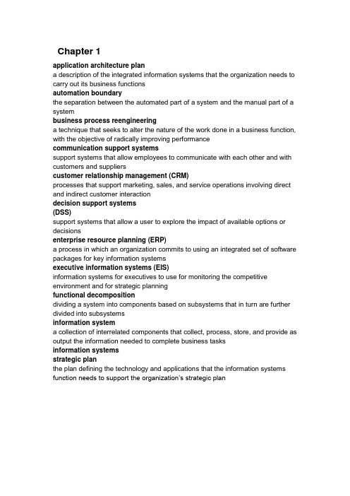
Chapter 1application architecture plana description of the integrated information systems that the organization needs to carry out its business functionsautomation boundarythe separation between the automated part of a system and the manual part of a systembusiness process reengineeringa technique that seeks to alter the nature of the work done in a business function, with the objective of radically improving performancecommunication support systemssupport systems that allow employees to communicate with each other and with customers and supplierscustomer relationship management (CRM)processes that support marketing, sales, and service operations involving direct and indirect customer interactiondecision support systems(DSS)support systems that allow a user to explore the impact of available options or decisionsenterprise resource planning (ERP)a process in which an organization commits to using an integrated set of software packages for key information systemsexecutive information systems (EIS)information systems for executives to use for monitoring the competitive environment and for strategic planningfunctional decompositiondividing a system into components based on subsystems that in turn are further divided into subsystemsinformation systema collection of interrelated components that collect, process, store, and provide as output the information needed to complete business tasksinformation systemsstrategic planthe plan defining the technology and applications that the information systems function needs to support the organization’s strategic planmanagement informationsystems (MIS)information systems that take information captured by transaction processing systems and produce reports that management needs for planning and control office support systemssupport systems that help employees create and share documents, including reports, proposals, and memosstrategic planninga process during which executives try to answer questions about the company such as where the business is now, where they want the business to be, and what they have to do to get theresubsystema system that is part of a larger systemsupersystema larger system that contains other systemssupply chain management (SCM)a process that seamlessly integrates product development, product acquisition, manufacturing, and inventory managementsystema collection of interrelated components that function together to achieve some outcomesystem boundarythe separation between a system and its environment that inputs and outputs must crosssystems analysisthe process of understanding and specifying in detail what the information system should dosystems analysta business professional who uses analysis and design techniques to solve business problems using information technologysystems designthe process of specifying in detail how the many components of the information system should be physically implementedtechniquesstrategies for completing specific system development activitiestechnology architecture plana description of the hardware, software, and communications networks required to implement planned information systemstoolssoftware products used to help develop analysis and design specifications and completed system componentstransaction processing systems (TPS)information systems that capture and record information about the transactions that affect the organizationChapter 2analysis phasethe phase of the SDLC whose objective is to understand the user needs and develop requirementsapplicationthe portion of the new information system that satisfies the user’s needs in the problem domainCASE toola computer-aided system engineering tool designed to help a systems analyst complete development tasksclass diagrama graphical model used in the object-oriented approach to show all of the classes of objects in the systemdata flow diagram (DFD)a graphical model showing the inputs, processes, storage, and outputs of a system produced in structured analysisdesign phasethe phase of the SDLC during which the system and programs are designed entity-relationship diagram (ERD)a graphical model of the data needed by a system, including things about which information is stored and the relationships among them, produced in structured analysis and information engineeringhelp deskthe availability of support staff to assist users with any technical or processing problem associated with an information systemimplementation phasethe phase of the SDLC during which the new system is programmed and installed incremental developmenta development approach that completes parts of a system in one or more iterations and puts them into operation for usersinformation engineeringa traditional system development methodology thought to be more rigorous and complete than the structured approach, because of its focus on strategic planning, data modeling, and automated toolsmodel 模型a representation of an important aspect of the real worldobject 对象a thing in the computer system that can respond to messagesobject-oriented analysis (OOA) 面向对象分析defining all of the types of objects that do the work in the system and showing what user interactions are required to complete tasksobject-oriented approach 面向对象方法an approach to system development that views an information system as a collection of interacting objects that work together to accomplish tasksobject-oriented design (OOD) 面向对象设计defining all of the types of objects necessary to communicate with people and devices in the system, showing how objects interact to complete tasks, and refining the definition of each type of object so it can be implemented with a specific language or environmentobject-oriented programming (OOP)writing statements in a programming language to define what each type of object does, including the messages that the objects send to each otherphaserelated system development activities, which are grouped into categories of project planning, analysis, design, implementation, and supportplanning phasethe initial phase of the SDLC, whose objective is to identify the scope of the new system and plan the projectproblem domainthe area of the user’s business for which a system is being developedprojecta planned undertaking that has a beginning and an end, and that produces a desired result or productrepositorya database that stores information about the system in a CASE tool, including models, descriptions, and references that link the various models togethersociotechnical systemsinformation systems that include both social and technical subsystems designed to work well togetherstructure charta graphical model showing the hierarchy of program modules produced by the structured design techniquestructured analysisa technique that helps the developer define what the system needs to do (the processing requirements), what data the system needs to store and use (data requirements), what inputs and outputs are needed, and how the functionswork together as a whole to accomplish tasksstructured approachsystem development using structured analysis, structured design, and structured programming techniquesstructured designa technique providing guidelines for deciding what the set of programs in an IS should be, what each program should accomplish, and how the programs should be organized into a hierarchystructured programa program or program module that has one beginning and one ending, and for which each step in the program execution consists of sequence, decision, or repetition constructssupport phasethe phase of the SDLC whose objective is to keep the system running productively after it is installedsystem development methodologycomprehensive guidelines to follow for completing every activity in the systems development life cycle, including specific models, tools, and techniquessystems development life cycle (SDLC)a project management framework organized into phases and activities techniquea collection of guidelines that help an analyst complete a system development activity or tasktoolsoftware support that helps create models or other components required in the projecttop-down programmingdividing more complex programs into a hierarchy of program modulesUnified Process (UP)an object-oriented system development methodology offered by Rational Softwarewaterfall approach 瀑布法an approach to executing an SDLC in which one phase leads (falls) sequentially into the next phaseChapter 3breakeven point 盈亏平衡点the point in time where the dollar benefits have offset the dollar costs business benefitsthe benefits that accrue to the organization; often measured in monetary terms client 顾客the person or group who funds the projectcontext diagrama data flow diagram (DFD) showing the scope of a systemcost/benefit analysis 盈亏分析the analysis to compare costs and benefits to see whether investing in the development of a new system will be beneficialcritical patha sequence of tasks that cannot be delayed without causing the project to be completed lateGantt chart 甘特图a bar chart that represents the tasks and activities of the project schedule intangible benefitsbenefits that accrue to the organization but which cannot be measured quantitatively or estimated accuratelynet present value (NPV)the present value of dollar benefits and costs for an investment such as a new systemoversight committeeclients and key managers who review and direct the projectpayback period 回收期the time period where the dollar benefits have offset the dollar costsPERT/CPMa technique for scheduling a project based on individual tasks or activities return on investment (ROI) 投资收益率a measure of the percentage gain from an investment such as a new systemproject managementorganizing and directing other people to achieve a planned result within a predetermined schedule and budgetproof of concept prototypea very preliminary prototype built to illustrate that a solution to a business need is feasiblesystem scope documenta document—containing description, business benefits, and system capabilities—to help define the scope of a new systemtangible benefitsbenefits that can be measured or estimated in terms of dollars and that accrue to the organizationtracking Gantt chart 跟踪甘特图a type of Gantt chart that indicates the current date and percentage of work completed for each taskuser 用户the person or group of persons who will use the new systemweighted scoringa method to prioritize projects based on criteria with unequal weightswork breakdown structure (WBS) 工作分解结构the hierarchy of phases, activities, and tasks of a project; one method to estimate and schedule the tasks of a projectChapter 4activity diagrama type of workflow diagram that describes the user activities and their sequential flowclosed-ended questions 封闭式问题questions that have a simple, definitive answerfunctional requirement 功能需求a system requirement that describes an activity or process that the system must performgroup support system (GSS)a computer system that enables multiple people to participate with comments at the same time, each on the user’s own computerjoint application design (JAD)a technique to define requirements or design a system in a single session by having all necessary people participatelogical modelany model that shows what the system is required to do without committing to any one technologymock-upan example of a final product that is for viewing only, and not executableopen-ended questions 可修整式问题questions that require discussion and do not necessarily have a simple, short answerperformance requirementa system requirement that describes an operational characteristic related to workload measures, such as throughput and response timephysical modelany model that shows how the system will actually be implementedprototype 原型a preliminary working model of a larger systemreliability requirementa system requirement that describes the dependability of a system, such as service outages, incorrect processing, and error detection and recoverysecurity requirementa system requirement that describes user access to certain functions and the conditions under which access is grantedstakeholders 社众all the people who have an interest in the success of a new systemstructured walkthrougha review of the findings from your investigation and of the models built based on those findingsswimlanea rectangular area on an activity diagram representing the activities done by a single agentsynchronization bara symbol in an activity diagram to control the splitting or uniting of sequential paths system requirements 系统需求specifications that define the functions to be provided by a systemtechnical requirement 技术需求a system requirement that describes an operational characteristic related to an organization’s environment, hardware, and softwaretransactiona single occurrence of a piece of work or an activity done in an organization usability requirementa system requirement that describes an operational characteristic related to users, such as the user interface, work procedures, on-line help, and documentation workflowa sequence of steps to process a business transactionChapter 5abstract classa class that cannot be instantiated (no objects can be created), existing only to allow subclasses to inherit its attributes, methods, and associationsactivitybehavior that the system performs when an event occurs (similar to a use case) aggregationwhole-part relationship between an object and its partsassociation class 关联类a class that represents a many-to-many relationship between two other classes associative entitya data entity that represents a many-to-many relationship between two other data entitiesattributeone piece of specific information about a thingcardinality 集的势the number of associations that occur among specific things, such as a customer places many orders and an employee works in one departmentclass 类the type or classification to which all similar objects belongcompositionwhole-part relationship in which the parts cannot be dissociated from the object concrete class 实体类a class that can be instantiated (objects can be created)data entitiesthe things the system needs to store information about in the traditional approach to information systemsdescriptive modelnarrative memos, reports, or lists that describe some aspect of a systemdomain model 版图a class diagram without methods, which is created as a requirements modelencapsulation 封装covering or protecting each object so that it contains values for attributes and methods for operating on those attributes, making the object a self-contained (and protected) unitevent 事件an occurrence at a specific time and place that can be described and is worth rememberingevent tablea table that lists events in rows and key pieces of information about each event in columnsexternal event 外部事件an event that occurs outside the system, usually initiated by an external agent or actorgeneralization/specialization hierarchieshierarchies that structure or rank classes from the more general superclass to the more specialized subclasses; sometimes called inheritance hierarchies graphical modeldiagrams and schematic representations of some aspect of a systemidentifier (key) 标识符an attribute that uniquely identifies a thinginheritancea concept that allows subclasses to share characteristics of their superclasses mathematical model 数学模型a series of formulas that describe technical aspects of a systemmethodsthe behaviors all objects of the class are capable of doingmultiplicity 多样性a synonym for cardinality (used with the object-oriented approach)n-ary relationshipa relationship among n (any number of) different types of thingsperfect technology assumptionthe assumption that events should be included during analysis only if the system would be required to respond under perfect conditionsrelationship 关系a naturally occurring association among specific things, such as an order is placed by a customer and an employee works in a departmentresponsean output, produced by the system, that goes to a destinationsource 来源an external agent or actor that supplies data to the systemstate event 状态事件an event that occurs when something happens inside the system that triggers the need for processingsystem controlschecks or safety procedures put in place to protect the integrity of the system temporal eventan event that occurs as a result of reaching a point in timeternary relationshipa relationship among three different types of thingstriggera signal that tells the system that an event has occurred, either the arrival of data needing processing or a point in timeunary (recursive) relationship 一元关系a relationship among two things of the same type, such as one person being married to another personuse casea series of actions that a system performs that result in a defined outcome (similar to an activity)whole-part hierarchieshierarchies that structure classes according to their associated componentsChapter 6 不考activity-location matrixa table that describes the relationship between processes and the locations in which they are performedactivity-data matrixa table that describes stored data entities, the locations from which they are accessed, and the nature of the accessesbalancingequivalence of data content between data flows entering and leaving a process and data flows entering and leaving a process decomposition DFDblack holea process or data store with a data input that is never used to produce a data outputcontext diagrama DFD that summarizes all processing activity within the system in a single process symbolCRUDacronym of create, read, update, and deletedata dictionarya repository for definitions of data flows, data elements, and data storesdata flowan arrow on a DFD that represents data movement among processes, data stores, and external agentsdata flow definitiona textual description of a data fl ow’s content and internal structuredata flow diagram (DFD)a diagram that represents system requirements as processes, external agents, data flows, and data storesdata storea place where data are held pending future access by one or more processes decision tablea tabular representation of processing logic containing decision variables, decision variable values, and actions or formulasdecision treea graphical description of process logic that uses lines organized like branches of a treeDFD fragmenta DFD that represents the system response to one event within a single process symbolevent-partitioned system model, or diagram 0a DFD that models system requirements using a single process for each event in a system or subsystemexternal agenta person or organization, outside the system boundary, that supplies data inputs or accepts data outputsInformation Engineering (IE)a system development methodology that focuses on strategic planning, data modeling, and automated tools, and is thought to be more rigorous and complete than the structured approachinformation overloaddifficulty in understanding that occurs when a reader receives too much information at one timelevel of abstractionany modeling technique that breaks the system into a hierarchical set of increasingly more detailed modelslocation diagrama diagram or map that identifies all of the processing locations of a system minimization of interfacesa principle of model design that seeks simplicity by limiting the number of connections among model componentsmiraclea process or data store with a data element that is created out of nothing processa symbol on a DFD that represents an algorithm or procedure by which data inputs are transformed into data outputsprocess decomposition diagrama model that represents the hierarchical relationship among processes at different levels of abstractionprocess dependency diagrama model that describes the ordering of processes and their interaction with stored entitiesrule of 7 ± 2the rule of model design that limits the number of model components or connections among components to no more than ninestructured Englisha method of writing process specifications that combines structured programming techniques with narrative EnglishChapter 7domain model class diagram, or domain modela class diagram that focuses on the user’s problem domain classes, describing the basic structure of classes and the conceptual data modelinteraction diagrameither a collaboration diagram or a sequence diagram that shows the interactions between objectslifeline, or object lifelinethe vertical line under an object on a sequence diagram to show the passage of time for the objectmessagethe communication between objects within a use caseprecondition 前置条件a set of criteria that must be true prior to the initiation of a use case postcondition 后置条件a set of criteria that must be true upon completion of the execution of a use case scenario, or use case instance 场景a particular sequence of steps within a use case; a use case may have several different scenariosstatechart diagrama diagram showing the life of an object in states and transitionssystem sequence diagrama diagram showing the sequence of messages between an external actor and the system during a use case or scenariotrue/false conditionpart of a message between objects that is evaluated prior to the message being sent to determine whether the message can be sentuse case diagrama diagram to show the various user roles and how those roles use the systemChapter8application deployment environmentthe configuration of computer equipment, system software, and networks for the new systembenchmarkan evaluation of a system against some standarddevelopment environmentthe programming languages, CASE tools, and other software used to develop application softwarefacilities managementthe outsourcing of all data processing and information technology to an outside vendorpackaged softwaresoftware that is already built and can be purchased as a packagerequest for proposal (RFP) 建议请求a formal document, containing details on the system requirements, sent to vendors to request that they bid on supplying hardware, software, and/or support servicesturnkey systema complete system solution, including software and hardware, that can be turned over to the purchasing organizationChapter 9architectural design 构架设计broad design of the overall system structure; also called general design or conceptual designbusiness logic layer 业务逻辑层the part of three-layer architecture that contains the programs that implement the business rules of the applicationcentralized architecturearchitecture that locates all computing resources in a central locationclient 客户机程序a process, module, object, or computer that requests services from one or more serversclustered architecturea group of computers of the same type that share processing load and act as a single large computer systemcomputer networka set of transmission lines, equipment, and communication protocols to permit sharing of information and resourcesdata layerthe part of three-layer architecture that interacts with the databasedetail designlow-level design that includes the design of specific program detailsdistributed architecturearchitecture that deploys computing resources in multiple locations connected by a computer networkextranet 外部网an intranet that has been extended outside the organization to facilitate the flow of informationinterface designersspecialists in user-interface design; also called usability consultants or human factors engineersInternet 因特网a global collection of networks that use the same networking protocol— TCP/IPintranet 内部网a private network that is accessible to a limited number of users, but which uses the same TCP/IP protocol as the Internetlocal area network (LAN) 局域网a computer network in which the distances are local, such as within the same buildingmiddlewarecomputer software that implements communication protocols on the network and helps different systems communicatemulticomputer architecturea group of dissimilar computers that share processing load through specialization of functionmultitier architecturearchitecture that distributes application related software or processing load across multiple computer systemsnetwork diagrama model that shows how application layers are distributed across locations and computer systemsrouternetwork equipment that directs information within the networkserver 服务器a process, module, object, or computer that provides services over a netwo rk single-computer architecturearchitecture that employs a single computer system executing allapplication-related softwarethree-layer architecture 三层构架a client-server architecture that divides an application into the view layer, business logic layer, and data layerview layer 观察层the part of three-layer architecture that contains the user interfacevirtual organizationa loosely coupled group of people and resources that work together as though they were an organizationvirtual private network (VPN)a network with security and controlled access for a private group but built on top of a public network such as the Internetwide area network (WAN)a computer network spread across large distances, such as a city, state, or nation World Wide Web (WWW), or Weba collection of resources such as files and programs that can be accessed over the Internet using standard protocolsChapter 10不考afferent data flowthe incoming data flow from a sequential set of DFD processescentral transformset of DFD processes that are located between the input and output processes computer programan executable entity made up of a set of modulesdata couplesthe individual data items that are passed between modules in a program call efferent data flowthe outgoing data flow in a sequential set of DFD processesmodulean identifiable component of a computer program that performs a defined function module cohesiona measure of the internal strength of a modulemodule couplingthe manner in which modules relate to each other; the preferred method is data couplingprogram callthe transfer of control from a module to a subordinate module to perform a requested servicepseudocodestructured-programming-like statements that describe the logic of a module structure charta hierarchical diagram showing the relationships between the modules of a computer programsystem flowcharta diagram that describes the overall flow of control between computer programs in a systemtransaction analysisthe development of a structure chart based on a DFD that describes the processing for several types of transactions。
Package‘mitools’October13,2022Title Tools for Multiple Imputation of Missing DataVersion2.4Author Thomas LumleyDescription Tools to perform analyses and combine results frommultiple-imputation datasets.Maintainer Thomas Lumley<********************.nz>Suggests RODBC,foreignImports DBI,methods,statsLicense GPL-2NeedsCompilation noRepository CRANDate/Publication2019-04-2605:00:03UTCR topics documented:imputationList (2)MIcombine (3)MIextract (4)pisamaths (5)smi (7)with.imputationList (8)withPV (9)Index1112imputationList imputationList Constructor for imputationList objectsDescriptionCreate and update imputationList objects to be used as input to other MI routines.UsageimputationList(datasets,...)##Default S3method:imputationList(datasets,...)##S3method for class characterimputationList(datasets,dbtype,dbname,...)##S3method for class imputationListupdate(object,...)##S3method for class imputationListrbind(...)##S3method for class imputationListcbind(...)Argumentsdatasets a list of data frames corresponding to the multiple imputations,or a list of names of database tables or viewsdbtype"ODBC"or a database driver name for DBI::dbDriver()dbname Name of the databaseobject An object of class imputationList...Arguments tag=expr to update will create new variables tag by evaluating expr in each imputed dataset.Arguments to imputationList()are passed tothe database driverDetailsWhen the arguments to imputationList()are character strings a database-based imputation list is created.This can be a database accessed through ODBC with the RODBC package or a database with a DBI-compatible driver.The dbname and...arguments are passed to dbConnect()or odbcConnect()to create a database connection.Data are read from the database as needed.For a database-backed object the update()method creates variable definitions that are evaluated as the data are read,so that read-only access to the database is sufficient.ValueAn object of class imputationList or DBimputationListMIcombine3 Examples##Not run:##CRAN doesn t like this exampledata.dir<-system.file("dta",package="mitools")files.men<-list.files(data.dir,pattern="m.\\.dta$",full=TRUE)men<-imputationList(lapply(files.men,foreign::read.dta))files.women<-list.files(data.dir,pattern="f.\\.dta$",full=TRUE)women<-imputationList(lapply(files.women,foreign::read.dta))men<-update(men,sex=1)women<-update(women,sex=0)all<-rbind(men,women)all<-update(all,drinkreg=as.numeric(drkfre)>2)all##End(Not run)MIcombine Multiple imputation inferenceDescriptionCombines results of analyses on multiply imputed data sets.A generic function with methods for imputationResultList objects and a default method.In addition to point estimates and variances, MIcombine computes Rubin’s degrees-of-freedom estimate and rate of missing information.UsageMIcombine(results,...)##Default S3method:MIcombine(results,variances,call=sys.call(),plete=Inf,...)##S3method for class imputationResultListMIcombine(results,call=NULL,plete=Inf,...)Argumentsresults A list of results from inference on separate imputed datasetsvariances If results is a list of parameter vectors,variances should be the correspond-ing variance-covariance matricescall A function call for labelling the resultsplete Complete-data degrees of freedom...Other arguments,not used4MIextractDetailsThe results argument in the default method may be either a list of parameter vectors or a list of objects that have coef and vcov methods.In the former case a list of variance-covariance matrices must be supplied as the second argument.The complete-data degrees of freedom are used when a complete-data analysis would use a t-distribution rather than a Normal distribution for confidence intervals,such as some survey ap-plications.ValueAn object of class MIresult with summary and print methodsReferences~put references to the literature/web site here~See AlsoMIextract,with.imputationListExamplesdata(smi)models<-with(smi,glm(drinkreg~wave*sex,family=binomial()))summary(MIcombine(models))betas<-MIextract(models,fun=coef)vars<-MIextract(models,fun=vcov)summary(MIcombine(betas,vars))MIextract Extract a parameter from a list of resultsDescriptionUsed to extract parameter estimates and standard errors from lists produced by with.imputationList. UsageMIextract(results,expr,fun)Argumentsresults A list of objectsexpr an expressionfun a function of one argumentDetailsIf expr is supplied,it is evaluated in each element of results.Otherwise each element of results is passed as an argument to fun.ValueA listSee Alsowith.imputationList,MIcombineExamplesdata(smi)models<-with(smi,glm(drinkreg~wave*sex,family=binomial()))betas<-MIextract(models,fun=coef)vars<-MIextract(models,fun=vcov)summary(MIcombine(betas,vars))pisamaths Maths Performance Data from the PISA2012survey in New ZealandDescriptionData on maths performance,gender,some problem-solving variables and some school resource variables.This is actually a weighted survey:see withPV.survey.design in the survey package for a better analyis.Usagedata("pisamaths")FormatA data frame with4291observations on the following26variables.SCHOOLID School IDCNT Country id:a factor with levels New ZealandSTRATUM a factor with levels NZL0101NZL0102NZL0202NZL0203OECD Is the country in the OECD?STIDSTD Student IDST04Q01Gender:a factor with levels Female MaleST14Q02Mother has university qualifications No YesST18Q02Father has university qualifications No YesMATHEFF Mathematics Self-Efficacy:numeric vectorOPENPS Mathematics Self-Efficacy:numeric vectorPV1MATH,PV2MATH,PV3MATH,PV4MATH,PV5MATH’Plausible values’(multiple imputations)for maths performanceW_FSTUWT Design weight for studentSC35Q02Proportion of maths teachers with professional development in maths in past yearPCGIRLS Proportion of girls at the schoolPROPMA5A Proportion of maths teachers with ISCED5A(math major)ABGMATH Does the school group maths students:a factor with levels No ability grouping between any classes One of these forms of ability grouping between classes for s One of theseforms of ability grouping for all classesSMRATIO Number of students per maths teacherW_FSCHWT Design weight for schoolcondwt Design weight for student given schoolSourceA subset extracted from the PISA2012lite R package,https:///pbiecek/PISA2012liteReferencesOECD(2013)PISA2012Assessment and Analytical Framework:Mathematics,Reading,Science, Problem Solving and Financial Literacy.OECD Publishing.Examplesdata(pisamaths)means<-withPV(list(maths~PV1MATH+PV2MATH+PV3MATH+PV4MATH+PV5MATH),data=pisamaths, action=quote(by(maths,ST04Q01,mean)),rewrite=TRUE)meansmodels<-withPV(list(maths~PV1MATH+PV2MATH+PV3MATH+PV4MATH+PV5MATH),data=pisamaths, action=quote(lm(maths~ST04Q01*PCGIRLS)),rewrite=TRUE)summary(MIcombine(models))smi7smi Multiple imputationsDescriptionAn imputationList object containingfive imputations of data from the Victorian AdolescentHealth Cohort Study.Usagedata(smi)FormatThe underlying data are in a data frame with1170observations on the following12variables.id a numeric vectorwave a numeric vectormmetro a numeric vectorparsmk a numeric vectordrkfre a factor with levels Non drinker not in last wk<3days last wk>=3days last wkalcdos a factor with levels Non drinker not in last wk av<5units/drink_day av=>5units/drink_day alcdhi a numeric vectorsmk a factor with levels non/ex-smoker<6days6/7dayscistot a numeric vectormdrkfre a numeric vectorsex a numeric vectordrinkreg a logical vectorSourceCarlin,JB,Li,N,Greenwood,P,Coffey,C.(2003)"Tools for analysing multiple imputed datasets"The Stata Journal3;3:1-20.Examplesdata(smi)with(smi,table(sex,drkfre))model1<-with(smi,glm(drinkreg~wave*sex,family=binomial()))MIcombine(model1)summary(MIcombine(model1))8with.imputationList with.imputationList Evaluate an expression in multiple imputed datasetsDescriptionPerforms a computation of each of imputed datasets in dataUsage##S3method for class imputationListwith(data,expr,fun,...)Argumentsdata An imputationList objectexpr An expressionfun A function taking a data frame argument...Other arguments,passed to funDetailsIf expr is supplied,evaluate it in each dataset in data;if fun is supplied,it is evaluated on each dataset.If all the results inherit from"imputationResult"the return value is an imputationResultList object,otherwise it is an ordinary list.ValueEither a list or an imputationResultList objectSee AlsoimputationListExamplesdata(smi)models<-with(smi,glm(drinkreg~wave*sex,family=binomial()))tables<-with(smi,table(drkfre,sex))with(smi,fun=summary)withPV Analyse plausible values in surveysDescriptionRepeats an analysis for each of a set of’plausible values’in a data set,returning a list suitable for MIcombine.That is,the data set contains some sets of columns where each set are multiple imputations of the same variable.With rewrite=TRUE,the action is rewritten to reference each plausible value in turn;with coderewrite=FALSE a new data set is constructed for each plausible value,which is slower but more general.UsagewithPV(mapping,data,action,rewrite=TRUE,...)##Default S3method:withPV(mapping,data,action,rewrite=TRUE,...)Argumentsmapping A formula or list of formulas describing each variable in the analysis that has plausible values.The left-hand side of the formula is the name to use in theanalysis;the right-hand side gives the names in the dataset.data A data frame.Methods for withPV dispatch on this argument,so can be written for,eg,survey designs or out-of-memory datasets.action With rewrite=TRUE,a quoted expression specifying the analysis,or a function taking a data frame as its only argument.With rewrite=FALSE,A functiontaking a data frame as its only argument,or a quoted expression with.DATAreferring to the newly-created data frame to be used.rewrite Rewrite action before evaluating it(versus constructing new data sets)...For methodsValueA list of the results returned by each evaluation of action,with the call as an attribute.NoteI would be interested in seeing naturally-occurring examples where rewrite=TRUE does not work See Alsopisamathswith.imputationListExamplesdata(pisamaths)models<-withPV(list(maths~PV1MATH+PV2MATH+PV3MATH+PV4MATH+PV5MATH),data=pisamaths, action=quote(lm(maths~ST04Q01*(PCGIRLS+SMRATIO)+MATHEFF+OPENPS,data=.DATA)),rewrite=FALSE)summary(MIcombine(models))##equivalentlymodels2<-withPV(list(maths~PV1MATH+PV2MATH+PV3MATH+PV4MATH+PV5MATH),data=pisamaths, action=quote(lm(maths~ST04Q01*(PCGIRLS+SMRATIO)+MATHEFF+OPENPS)),rewrite=TRUE)summary(MIcombine(models2))Index∗datasetspisamaths,5smi,7∗htestMIcombine,3∗manipimputationList,2MIcombine,3MIextract,4with.imputationList,8cbind.imputationList(imputationList),2 dim.imputationList(imputationList),2 dimnames.imputationList(imputationList),2 imputationList,2,8MIcombine,3,5MIextract,4,4pisamaths,5,9print.imputationList(imputationList),2 print.MIresult(MIcombine),3rbind.imputationList(imputationList),2 smi,7summary.MIresult(MIcombine),3update.imputationList(imputationList),2vcov.MIresult(MIcombine),3with.imputationList,4,5,8,9withPV,911。
软件设计师-计算机专业英语(四)(总分30, 做题时间90分钟)综合知识试题It should go without saying that the focus of UML is modeling. However, what that means, exactly, can be an open-endedquestion. (1) is a means to capture ideas,relationships,decisions, and requirements in a well-defined notation that can be applied to many different domains. Modeling not only means different things to different people, but also it can use different pieces of UML depending on what you are trying to convey. In general, a UML model is made up of one or more (2) . A diagram graphically represents things, and the relationships between these things. These (3) can be representations of realworldobjects,pure software constructs, or a description of the behavior of some other objects. It is common for an individual thing to show up on multiple diagrams; each diagram represents a particular interest, or view, of the thing being modeled. UML 2.0 divides diagrams into two categories: structural diagrams and behavioraldiagrams. (4) are used to capture the physical organization of the things in your system, i.e., how one object relates toanother. (5) focus on the behavior of elements in a system. For example, you can use behavioral diagrams to capture requirements, operations, and internal state changes for elements.SSS_SINGLE_SEL1.A ProgrammingB AnalyzingC DesigningD ModelingSSS_SINGLE_SEL2.A viewsB diagramsC userviewsD structurepicturesSSS_SINGLE_SEL3.A thingsB picturesC languagesD diagramsSSS_SINGLE_SEL4.A ActivitydiagramsB Use-casediagramsC StructuraldiagramsD BehavioraldiagramsSSS_SINGLE_SEL5.A Activity diagramsB Use-case diagramsC Structural diagramsD BehavioralObject-oriented analysis (OOA) is a semiformal specification technique for the object-oriented paradigm. Object-oriented analysis consists ofthree steps. The first step is (6) . It determines how the various results **puted by the product and presents this information in the form of a (7) and associated scenarios. The second is (8) , which determines the classes and their attributes, then determines the interrelationships and interaction among the classes. The last step is (9) , which determines the actions performed by or to each class or subclass and presents this information in the form of (10) .SSS_SINGLE_SEL6.A use-casemodelingB classmodelingC dynamic modelingD behavioralmodelingSSS_SINGLE_SEL7.A collaborationdiagramB sequencediagramC use-case diagramD activity diagramSSS_SINGLE_SEL8.A use-casemodelingB classmodelingC dynamicmodelingD behavioralmodelingSSS_SINGLE_SEL9.A use-casemodelingB classmodelingC dynamicmodelingD behavioralmodelingSSS_SINGLE_SEL10.A activity diagramB component diagramC sequence diagramD state diagramPeople are indulging in an illusion whenever they find themselves explaining at a cocktail(鸡尾酒 ) party, say, that they are "in computers," or " in **munications," or "in electronic funds transfer". The implication is that they are part of the high-tech world. Just between us, they usually aren't. The researchers who made fundamental breakthroughs in those areas are in a high-tech business. The rest of us are (11) of their work. We **puters and other new **ponents to develop our products or to organize our affairs. Because we go about this work in teams and projects and other tightly knit working group(紧密联系在一起的工作小组 ), we are mostly in the**munication business. Our successes stem from good humaninteractions by all participants in the effort, and our failures stem from poor human interactions.The main reason we tend to focus on the (12) rather than the human side of work is not because it's more (13) , but because it's easier to do. Getting the new disk drive installed is positively **pared to figurine out why Horace is in a blue funk(恐惧)or why Susan is dissatisfied with **pany aver only a few months. Human interactions **plicated and never very crisp(干脆的,干净利落的) and clean in their effects, but they matter more than any other aspect of the work.If you find yourself concentrating on the (14) rather than the (15) , you're like the vaudeville character(杂耍人物)wholoses his Keys on a dark street and looks for them on the adjacent street because, as he explains, "The light is better there!\SSS_SINGLE_SEL11.A creatorsB innovatorsC appliersD inventorsSSS_SINGLE_SEL12.A technicalB classicalC socialD societalSSS_SINGLE_SEL13.A trivialB crucialC minorD insignificantSSS_SINGLE_SEL14.A technologyB sociologyC physiologyD astronomySSS_SINGLE_SEL15.A technologyB sociologyC physiologyD astronomyObserve that for the programmer, as for the chef, the urgency of the patron(顾客)may govern the **pletion of the task, but it cannot govern the **pletion. An omelette(煎鸡蛋 ), promised in two minutes, may appear to be progressing nicely. But when it has not set in two minutes, the customer has two choices—waits or eats it raw. Software customers have had (16) choices.Now I do not think software (17) have less inherent courage and firmness than chefs, nor than other engineering managers. But false (18) to match the patron's desired date is much **mon in our discipline than elsewhere in engineering. It is very (19) to make a vigorous, plausible, and job risking defense of an estimate that is derived by no quantitative method, supported by little data, and certified chiefly by the hunches of the managers.Clearly two solutions are needed. We need to develop and publicize productivity figures, bug-incidence figures, estimating roles, and so on. The whole profession can only profitfrom (20) such data. Until estimating is on a sounder basis, individual managers will need to stiffen their backbones and defend their estimates with the assurance that their poor hunches are better than wish derived estimates.SSS_SINGLE_SEL16.A noB the sameC otherD lots ofSSS_SINGLE_SEL17.A TestersB constructorsC managersD architectsSSS_SINGLE_SEL18.A TasksB jobsC WorksD schedulingSSS_SINGLE_SEL19.A easyB difficultC simpleD painlessSSS_SINGLE_SELA sharingB excludingC omittingD ignoringWhy is (21) fun? What delights may its practitioner expect as his reward? First is the sheer joy of making things. As the child delights in his mud pie, so the adult enjoys building things, especially things of his own design. Second is the pleasure of making things that are useful to other people. Third is the fascination of **plex puzzle-like objects of interlocking moving parts and watching them work in subtle cycles, playing out the consequences ofprinciples built in from the beginning. Fourth is the joy of always learning, which springs from the(22) nature of the task. In one way or another the problem is ever new, and its solver learns something:sometimes (23) , sometimes theoretical, and sometimes both. Finally, there is the delight of working in such a tractable medium. The (24) , like the poet, works only slightly removed from pure thought-stuff. Few media of creation are so flexible, so easy to polish and rework, so readily capable of realizing grand conceptual structures.Yet the program (25) , unlike the poet's words, is real in the sense that it moves and works, producing visible outputs separate from the construct itself. It prints results, draws pictures, produces sounds, moves arms. Programming then is fun because it gratifies creative longings built deep within us and delights sensibilities we have in common with all men.SSS_SINGLE_SEL21.A programmingB composingC workingD writingSSS_SINGLE_SEL22.A repeatingB basicC non-repeatingD advanceSSS_SINGLE_SELA semanticB practicalC lexicalD syntacticalSSS_SINGLE_SEL24.A poetB architectC doctorD programmerSSS_SINGLE_SEL25.A constructB codeC sizeD scaleFor nearly ten years, the Unified Modeling Language (UML) has been the industry standard for visualizing, specifying, constructing, and documenting the (26) of a software-intensive system. Asthe (27) standard modeling language, the UML **munication and reduces confusion among project (28) The recent standardization of UML 2.0 has further extended the language's scope andviability.Its inherent expressiveness allows users to(29) everything from enterprise information systems and distributed Web-based applications to real-time embedded systems. The UML is not limited to modeling software. In fact, it is expressive enough to model (30) systems, such as workflow in the legal system, the structure and behavior of a patient healthcare system, software engineering in **bat systems, and the design of hardware. To understand the UML, you need to form a conceptual model of the language, and this requires learning three major elements: the UML's basic building blocks, the rules that dictate how those building blocks may be put together, and **mon mechanisms that apply throughout the UML.SSS_SINGLE_SEL26.A classesB componentsC sequencesD artifactsSSS_SINGLE_SEL 27.A realB legalC de factoD illegalSSS_SINGLE_SEL 28.A investorsB developersC designersD stakeholdersSSS_SINGLE_SEL 29.A modelB codeC testD modifySSS_SINGLE_SEL 30.A non-hardwareB non-softwareC hardwareD software1。