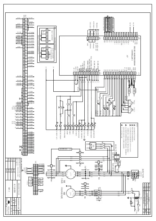
阿特拉斯GA 90-315 空压机电路图.
- 格式:doc
- 大小:238.50 KB
- 文档页数:2


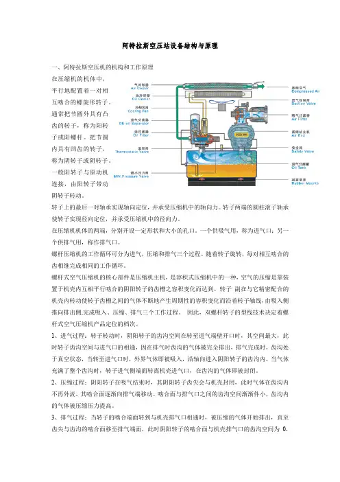
阿特拉斯空压站设备结构与原理一、阿特拉斯空压机的机构和工作原理在压缩机的机体中,平行地配置着一对相互啮合的螺旋形转子。
通常把节圆外具有凸齿的转子,称为阳转子或阳螺杆。
把节圆内具有凹齿的转子,称为阴转子或阴转子。
一般阳转子与原动机连接,由阳转子带动阴转子转动。
转子上的最后一对轴承实现轴向定位,并承受压缩机中的轴向力。
转子两端的圆柱滚子轴承使转子实现径向定位,并承受压缩机中的径向力。
在压缩机机体的两端,分别开设一定形状和大小的孔口。
一个供吸气用,称为进气口;另一个供排气用,称作排气口。
螺杆压缩机的工作循环可分为进气,压缩和排气三个过程。
随着转子旋转,每对相互啮合的齿相继完成相同的工作循环。
螺杆式空气压缩机的核心部件是压缩机主机,是容积式压缩机中的一种,空气的压缩是靠装置于机壳内互相平行啮合的阴阳转子的齿槽之容积变化而达到。
转子副在与它精密配合的机壳内转动使转子齿槽之间的气体不断地产生周期性的容积变化而沿着转子轴线,由吸入侧推向排出侧,完成吸入、压缩、排气三个工作过程。
因此,双螺杆转子的型线技术决定着螺杆式空气压缩机产品定位的档次。
1、进气过程:转子转动时,阴阳转子的齿沟空间在转至进气端壁开口时,其空间最大,此时转子齿沟空间与进气口的相通,因在排气时齿沟的气体被完全排出,排气完成时,齿沟处于真空状态,当转至进气口时,外界气体即被吸入,沿轴向进入阴阳转子的齿沟内。
当气体充满了整个齿沟时,转子进气侧端面转离机壳进气口,在齿沟的气体即被封闭。
2、压缩过程:阴阳转子在吸气结束时,其阴阳转子齿尖会与机壳封闭,此时气体在齿沟内不再外流。
其啮合面逐渐向排气端移动。
啮合面与排气口之间的齿沟空间渐渐件小,齿沟内的气体被压缩压力提高。
3、排气过程:当转子的啮合端面转到与机壳排气口相通时,被压缩的气体开始排出,直至齿尖与齿沟的啮合面移至排气端面,此时阴阳转子的啮合面与机壳排气口的齿沟空间为0,即完成排气过程,在此同时转子的啮合面与机壳进气口之间的齿沟长度又达到最长,进气过程又再进行。

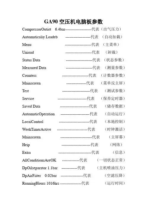
GA90空压机电脑板参数CompressorOutiet 6.4bar--------------------代表(出气压力)Automaticaliy Loadeb -------------------代表(自动加栽)Menu --------------------代表(主菜单)Unioad --------------------代表(卸栽)Status Data --------------------代表(状态参数)Measured Data --------------------代表(测量参数)Counters --------------------代表(计数器参数)Mainscreen ---------------代表(菜单反主屏)Test ---------------------代表(测试参数)Service ----------------------代表(保养定时器)Saved Data ----------------------代表(储存数据)AutomaticOperation ----------------------代表(自动运行)LocaiControl -----------------------代表(本地控制)WeekTimerActive -----------------------代表(时钟激活)Mainscreen ------------------------代表(主屏幕)Heip ----------------------代表(网络)Extra -------------------------代表(信息)AllConditionsAreOK -------------代表(一切状态正常)DpOilseparator 1.1bar ------------代表(主机喷油压力)DpAirFiiter 0.02bar -----------------代表(空滤压降)RunningHours 1016hrs ----------------代表(运行时间)LoadedHours 980hrs -------------代表(加栽时间)MotorStarts 945number ------代表(电机启动次数)DisplaiayTest --------------代表(不测试)SafetyValveTest -----------代表(安全测试)Menu ------------代表(安全阀)Parameters ------------代表(界限)Protections -----------代表(保护值)Service Plan --------代表(保养时间) Last Shutdown 1 -----------代表(上次故障停机) Loading Pressure ---------代表(加载压力) Unloading Pressure -------代表(卸载压力) Clock Function ------代表(时钟功能) Configuration --------------------代表(配置) Time ----------------------代表(时间) Date ----------------------------代表(日期) Date Domat DD/MMYY ---代表(日期格式) Elementoutlet-------------代表(头出口温度)Shutdwarnmax--------------代表(故障停机报警最大值) Servicerequire-------------代表(需要保养) Emergencystop-----------代表(紧急停机)Hightemperaturealarm -------代表(温度报警)LengGanmachinedewpoinetemptrature代表(干机露点温度)Oilgasseparatordifferenialpressure----代表(油气分离器压差)Fanoverload ----------------------------代表(风机过载)Hoseoverload ----------------------------代表(主机过载)Remotelyseule -------------------------代表(远程启动)Pressuresensorfauit-----------------------代表(压力传感器故障)The eemperaeuresensor------------------代表(温度传器故障)。
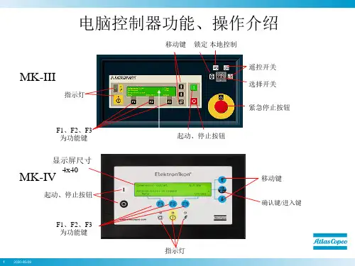
阿特拉斯螺杆空压机说明书一. 控制屏(图1.1)电脑显示屏/按钮/键代号名称功能1 停机按钮按此键停止空气压缩机,显示屏退出.空压机将空载运行大约30秒后停机.2 启动按钮按此按键启动空压机.显示屏显示调节器的运行状态.显示屏退出(如果空压机手动调为空载时)3 显示器显示出空压机的运转状态,协助需求或故障4 翻业按键在显示屏上翻页5 横移按键用水平箭头选择显示参数,只有向右的箭头对应的参数才能修改6 LED上的电压显示开关开启时的电压7 LED总报警当维护器警告或停机警告条件存在时或传感器不受控制时报警灯亮8 LED总在传感器的停机功能消失或紧急停机后的情况下报警灯会闪烁.9 功能键控制并执行程序.S3 紧急停机按钮在紧急情况下立即停止空压机,在修复后.将此按钮拔出.10 报警符号11 自动运行符号12 电源指示灯(1.1)二. 功能键使用的功能键:手动调节空压机的负荷调出或设定程序重新设定电动机的过负荷,停机,维护器信息或紧急停机.进入调节器所收集的数据.功能键都根据显示菜单的不同而不同.实际上都缩写并显示有关键的最底部一行,普通的缩写如下:缩写名称功能Add 增加指令用来增加空压机的自动启动/停机(日期)Back 返回指令返回到的选择或菜单Canc 取消当设定参数有误时.用来取消已设定的数dle 删除用来删除空压机的自动启动/停机时间Help 帮助帮助寻找Atlas Copco的内部地址Lim 上下限显示允许设定的上下极限数据Load 负载手动操作空压机负载Main 回到主目录从任一画面回到主目录Menu 菜单从主画面开始可进入子目录Menu 菜单从任一子目录返回到先前的目录Mod 修改修改设定参数Prog 编写输入将新的设定数据编写输入Rset 重新设定重新设定计时器及信息Rtrn 回归回归到前一页或前一目录Unld 空载手动操作空压机空载Xtra 额外的找寻调节器的构造模式三. 控制程序的功能程序/功能说明主屏幕简单地显示空压机的运转状态,是进入所有功能画面的出入口状态数据调出空压机的维护功能状况:停机.停机警告,维修期限快到的警告以及警告的数据,也可重新设定停机参数,马达超载和维修条件的数据.测量数据可调出:实际测量数据,还有如马达的超负荷保护这样一些输入数据计数器可调出:运行时间,带负荷运转小时数,马达开启次数,电脑运行时间数,负荷循环次数.试验试验显示屏修改设定修改以下设定:参数(如空载和负载时的压力)保护(如停机温度)维护计划.维护器调出维护计划并重新设定计时器已存数据调出上次关机,紧急停机时已存的数据1.5.2 主屏幕当开启电源开关时,主屏幕自动简单地显示空压机的操作状况.Delivery Air(输送空气)Bar(压力) 7.0 ↓Auto Loaded(自动负载)Menu(菜单) Unld(空载)F1 F2 F3如果功能键或↓几分钟不用的话显示屏就自动返回到主屏幕.无论在哪个子目录,只要按:Main就会返回到主目录.1.5.3 调出其他子菜单.从主目录开始: 用↓可快速浏览空压机的实际状态(见1.5.4节) .按Menu键(F1),供选择的数据就会跟在水平箭头后面:也可按横向移动箭头5来选择这个菜单或用↓来翻页到带有水平箭头的子目录为止,然后按水平键来选择这个菜单.1.5.4 迅速查看空压机的实际状态步骤1.从主目录开始(见1.5.2节),按↓键,就会显示相似下面的一个画面:Auto Operation(自动运转)Local Control(负荷控制)Tiner Active(激活计时器)Main (主画面) Help Xtra ↓F1 F2 F3图1.11所示为空压机实际状态显示第一行指出调节器的运行是自动还是手动的:<Auto Operation>表示调节器自动调节空压机的运转.如:Local(负载),Unlocal(空载),根据程序参数Sotp(停机)和 Restart(重启).<Man Operation>表示手动操作,如果在主屏幕上按了”Unload”键后调节器的自动压力控制就被打断了.第二行指出调节器是现场控制方式(Local control)还是远程控制方式(Remote control): <Local control>表示Start/Stop,load/unload(即开启/停止,负载/空载)的按钮是激活状态,可直接按.<Remote control>表示功能键是远方控制的,就地操作无效.第三行表示为计时器的开机停机命令是否在激活状态,见(1.15.13)2. 按↓键可以获得其它数据(如空压机的实际运行条件)1.5.5 状态数据菜单状态数据子目录给出了有关空压机保护功能的状态信息(如停机 .停机警告,维护器警告和一般警告)以及重新设定停止,马达超载和服务条件.步骤:从主屏幕开始(见1.5.2)按Menu(F1),用水平箭头选择状态数据.按横向移动键(LED中的5)1.5.5.1无信息存在在这种情况下,LED的7不存在,显示屏的信息表明所有条件正常(Fig1.12)All conditionsAre OKMenuF1 F2 F3图1.12状态数据屏的实例1.5.5.2 有停机信息存在在空压机停止时,LED中7会闪光.如果是由于空压机的出口温度过高导致的停机,就会显示以下屏幕: Element outletC 122Shd Max 120Menu** **RsetF1 F2 F3图1.13状态数据屏的实例1. 指示器(**)会闪光.屏幕显示传感器(空压机的出口)的实际可读温度(122℃),及空压机停机(Shd)设定(120℃).2. 可以继续翻页到其它菜单,检查其它参数值.当返回到数据菜单时,可供选择的(“Shutdowns”会闪光,按横向移动键5返回到停机屏幕来选择(“Shutdowns”).重新设定停机参数1. 关闭电源开关后处理问题,在修复完毕并且停机显示消失后,开启电源开关,按Rset(重新设定)键.2. 按Menu和 Main键返回主屏幕并按I键重新启动空压机.马达超载之重设1. 关闭电源开关并处理问题,过负荷继电器(F2)冷却后会自动重新设定,但冷却风扇的断路器(Q15)必须重置.开启电源开关,按Rset(重新设定)键.2. 按Menu和Main键返回主屏幕并重启空压机.1.5.5.3存在停机警告信息1.如有停机警告出现,LED上的7灯亮,会出现类似下面的屏幕:Delivery airBar 7.0*Shutd Warn*Menu** **UnldF1 F2 F3图1.14停机报警的实例2指示器(**)闪光和信息*Shutd Warn*会交替出现,无论空压机是空载还是带负载运行.3. 按Menu和横向移动键5来选择状态数据菜单:保护(Protection)会闪光.4. 按横向移动键5来选择报警闪光项.屏幕显示如下:Element outletC 116Shdw Max 110Menu** **F1 F2 F3图1.15停机报警的实例屏幕上说明空压机温度太高(116℃),参照第六节修复问题.5. 如有需要,按O键直到空压机停止为止.6. 关闭电源开关,检查并修复空压机.7. 当报警条件除去时,报警信号也会消失.1.5.5.4出现维护器报警信号1.LED上的7灯亮,会出现类似下面的屏幕,如图1.16所示:Delivery airBar 7.0*Serv Requir*Menu** **UnldF1 F2 F3图1.16报警屏幕的实例2指示器(**)闪光和维护器报警信号会交替出现,无论空压机是空载运行还是带负荷运行.3. 按Menu和横向移动键5来选择状态菜单:维护器项(Service),闪光4. 翻页并按横向移动键5来选择下面二报警闪光项:<Inputs>:如果维护器超出了预设的报警标准(如油分的最高压力露点).见8.2节.<Plans>:如果维护计划时间间隔超限.5. 停止空压机并关闭电源6. 如果维护器信息为上述的<Inputs>(油分故障):就更换分离器.开启电源,翻到状态数据菜单的<Inputs>并按Rset键,重新设定维护信息.7. 如果维护器信息为上述的<Plans>:执行有关指示计划的维修动作,重新设定1.5.15节里记述的有关计划的计时器.1.5.5.5 出现报警信号及处理1. LED上的7灯亮,在屏幕上会出现一个报警信息.2. 指示器(**)闪光和服务报警信号会交替出现,无论空压机是空载运行还是负荷运行.此警告指出:空压机的冷却水,冷却水的出口温度超过了设计报警温度.内置干燥机(配有干燥机的空压机),露点温度超出了报警温度.3. 停机4. 关闭电源,检查并修复空压机.1.5.6 测量数据菜单功能:按Menu(F1) 按↓到 Measured data 画面按横向移动箭头5激活菜单Delivery airBar 7.0Menu ↓F1 F2 F3图1.17状态数据屏的实例2按↓可见一组实际测量数据(见图1.9)3. 如果有一个传感器连接到了停机,维护器或报警功能上面的话,只要按横向移动箭头5就可以调出与其有关的实际测量数据.1.5.7 计数器菜单功能: 允许操作员调出:运行时间带负荷时间马达启动次数电脑运行时间步骤1. 从主屏幕开始(见1.5.2) 按Menu(F1)按↓到Counters画面按横向移动箭头5激活此菜单2. 按↓就可见到上面提到的数据.(也可见图1.9)1.5.8 试验菜单功能可修改图1.9提到的许多数据.步骤1. 从主屏幕开始(见1.5.2) 按Menu(F1)按↓到Modify setting画面,按横向移动箭头5激活菜单2. 水平箭头将指向Display test选项.3. 按→←第一条(负载压力)及它的设定都会出现4. 使用↓翻到水平箭头指向的已修改的参数.1.5.10.1 空/负载上下限压力修改压力段如果合适的话,操作员可以随空/负载压力的不同而设定二个压力段(1段和2段).1段的设定指示为:<Loading pressure>及<Unloading pressure>,2段的设定指示为:<Loading pressure2>及<Unloading pressure2>.例如:1 段压力设定:Loading pressur: 6.4barUnloading pressur: 7.0bar2 段压力设定:Loading pressur: 4.0barUnloading pressur: 6.0bar步骤1. 负载压力参数的设定1) 参照上节选择负载压力参数:Loading pressBar 6.0Menu Mod ↓F1 F2 F3图1.18为修改参数菜单3).Lim(F2)键可查看参数的上下限,用↓或↑调整压力参数值.4).按Prong(F1)编写输入新设定值,或按Canc(F3)取消修改操作.2. 修改空载压力的设定同上.3. 如果需要修改空/负载压力段2的话,则重复上述步骤..1.5.11 修改保护设定功能1. 修改保护设定停机保护(<Shd>)由于出口温度的问题停机警告(<Shdw>)由于出口温度的问题警告(<Warn>),如:冷却水回路或露点警告维护器报警(<Serv>),如:DP油分故障(最大压力降)2. 检查空压机的一些情况,如:马达超载通讯的状态.图1.9所示的参数表.注意:有些参数不能修改步骤1. 从主屏幕开始(见1.5.2)按Menu(F1)按↓到Modify setting画面,按横向移动箭头5激活此菜单2. 用↓翻页,水平箭头将指向Protection选项.3. 按→←第一条(Delivery air)及它的值都会出现.4. 使用↓翻到水平箭头指向的已修改的参数.1.5.11.1 温度上下限之设定修改1.参阅上节选择出口温度参数(Element outet):Element OutletC 94 →Shd Max 120Menu Mod ↓F1 F2 F3图1.20为修改参数菜单2.上屏幕显示的是正常温度94℃及停机温度120℃.按MOD(F2),数字120闪动,如图1.21所示: Element OutletC 120(闪动)Prog Lim Canc ↓F1 F2 F3图1.21为修改参数菜单3. Lim(F2)键可查看参数的上下限。
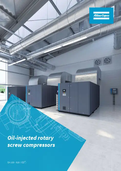
Oil-injected rotary screw compressors GA 180 - 315 (VSD+)Highest reliability, lowestoperating costsThe shortest route to maximize your profitability is to minimize youroperational costs. With up to 80% of a compressor lifecycle cost coming fromthe energy it consumes, this should be a clear focus. Atlas Copco's GAcompressors with SmartInjection enabled compression elements and IE4 orbetter class motors are designed to achieve significant energy savings whileproviding long and trouble-free life even in the harshest environmentalconditions.GA 180 – 315 (VSD+)EfficiencyAt the heart of the GA compressors are state-of-the-artcompression elements with SmartInjection technologyand high efficiency oil cooled IE4 or better class motors.This highly efficient drive train coupled with generouscooling capacity, low internal pressure drops and precisecontrol from the Elektronikon®Touch ensures optimumefficiency.ReliabilityThe GA compressor's drive train is IP66 rated protecting itcompletely from environmental dust and moistureensuring it can operate reliably in the toughest conditionsand at ambient temperatures up to 55°C/131°F.ServiceabilityService time is reduced to a minimum with all serviceparts grouped together for ease of access and, if greateraccess is required, the patented portal design enables fullaccess to all components. Each component has also beendesigned for serviceability, halving the time required toservice compared to traditional designs.3It's important to have high quality air, because contaminated air creates extra costs. It is better to avoid system contamination rather than deal with the consequences such as product spoilage, maintenance costs, replacing pipe work or leakages. Atlas Copco offers a range of quality air solutions.Clean air reduces operating costs.The GA 180-315 VSD+ is designed to deliver quality air.• Multiple smaller cartridges simplify and reduce service times and minimize oil carry over.• The GA full feature comes with an integrated dryer for greater air quality.• Guaranteed dewpoint of 3°C/37°F• Continuously monitored dew point.• New oil separator vessel with filter cartridges.Integrated air quality GA 180 – 315 (VSD+)Air dryersOur range of air dryers protect your systems and processes in a reliable, energy-efficient and cost-effective way.Protecting your systems and processesTreated air helps prevent pipework corrosion, product spoilage and premature failure of pneumatic equipment.Maintaining the quality of your end productA complete range of products with dew points from +3 to -70 °C to ensure the correct air quality for your application.Energy-efficient air dryersAll our air dryers are designed to perform in the most energy-efficient and environmentally friendly way.5Over 80% of a compressor’s lifecycle cost is taken up by the energy it consumes. Moreover, the generation of compressed air can account for more than 40% of a plant’s total electricity bill. To cut your energy costs, Atlas Copco pioneered Variable Speed Drive (VSD) technology in the compressed air industry. VSD leads to major energy savings, while protecting the environment for future generations. Thanks to continual investments in this technology, Atlas Copco offers the widest range of integrated VSD compressors on the market.LegendA =LossesB =Speed1 =Total losses traditional element2 =Total losses AC elementVariable Speed Drive (VSD)Atlas Copco's VSD technology closely follows the air demand by automatically adjusting the motor speed. This results in large energy savings of up to 35%. The Life Cycle Cost of a compressor can be cut by an average of 22%. In addition, lowered system pressure with VSD minimizes energy use across your production dramatically. Legend42% =Energy35% =Energy savings with VSD12% =Investment11% =MaintenanceVSD savings GA 180 – 315 (VSD+)Most production processes create fluctuating levels of demand which, in turn, can create energy waste in low use periods. Using the Elektronikon®unit controller, you can manually or automatically switch between two different setpoints to optimize energy use and reduce costs at low use times. In addition, the sophisticated algorithm runs the drive motor only when needed. As the desired setpoint is maintained while the drive motor’s run time is minimized, energy consumption is kept to a minimum.LegendA =Power consumptionB =TimeC =Energy SavingDual set-point and automatic stop• SmartInjection provides exact amount of oil required to element ensuring it always works at peak efficiency.• High efficiency IE4 (Fixed Speed) and IE5 (VSD+) motor.• Integrated energy recovery system recovers up to 78% of energy from integrated motor and element oil circuit.• Dual speed or VSD fan for energy efficiency in lower temperatures.Components designed for efficiencyThe Elektronikon®unit controller is specially designed to maximizethe performance of your compressors and air treatment equipmentunder a variety of conditions. Our solutions provide you with keybenefits such as increased energy efficiency, lower energyconsumption, reduced maintenance times and less stress… lessstress for both you and your entire air system.Elektronikon Mk5 touch7Monitor your compressed air installation with SMARTLINK Knowing the status of your compressed air equipment at all times is the surest way to achieve optimal efficiency and maximum availability.Go for energy efficiencyCustomized reports on the energy efficiency of your compressor room.Increase uptimeAll components are replaced on time, ensuring maximum uptime. Save moneyEarly warnings avoid breakdowns and production loss.SMARTLINKMinimizing Excess PressureOptimizer 4.0 minimizes the generation of excess compressed air bystarting and stopping compressors. Its user friendly interfaceenables you to set multiple pressure bands, allowing you tooptimize your compressor installation for varying circumstances,such as non-productive hours.Full VSD BenefitsWith Optimizer 4.0 you can realize the full energy saving potential ofVSD (Variable Speed Drive). It regulates the VSD to ensure that thecompressed air output is proportional to the demand, preventinghigher pressures than required, excess unloaded running, andspiraling energy costs.Improving UptimeOptimizer 4.0 effectively eliminates production downtime causedby unexpected system pressure drops, because it regulates thesystem pressure instead of the compressor output pressure.This means Optimizer 4.0 will automatically adjust the systempressure to compensate for pressure drops due to filters, piping anddryers for example.We also provide additional functionality and services on Optimizer4.0 to ensure that your energy savings will stand the test of time.Even when your installation needs adaptations or your demandchanges.Optimizer 4.0GA 180 – 315 (VSD+)• Service parts grouped together for ease of access.• Reduced service time for greater uptime.• Portable design enables full access to all components.• All components designed for serviceability.• Oil cooled motors require no service interventions.Designed for serviceabilityEase of maintenanceEvery type of compressor and vacuum pump needs a specific oil to achieve maximum uptime, performance and lifetime. Our compressed air fluids and lubricants cover all your needs.Unique mix of additivesTailored to the specific needs of your equipment.Anti-oxidationThe high-quality oil ensures maximum protection.Prevent foamingAnti-foaming improves your air pressor oils, lubricants and fluids9Reduce your total cost of ownership and benefit from optimal performanceSave costsOptimal maintenance will reduce the operational cost of your compressed air and vacuum system.Increase operational efficiencyOur maintenance expertise makes life easier when it comes to resource management.High uptime and performanceSpecialist service keeps your equipment running as it should, protecting your investment.Maximize your resources with a Service Plan GA 180 – 315 (VSD+)Reliable and continuous operation of the compressor in hot and humid environments up to :– max. 55°C ( 131°F ) for fixed speed pack – max. 50°C ( 121°F ) for VSD packHigh ambient temperature variantContinuous SPM “Shock Pulse Measurement” monitoring system of the compressor element & motor bearings. The sensors are connected to the Elektronikon ®which is showing the individual vibration levels.Alarm and/or shutdown levels can be programmed during commissioning of the compressor. With this monitoring system, the compressor can run longer, since overhaul can be done when needed and preventive maintenance can be organized.Shock pulse monitoringThe energy recovery system consists of a build-in stainless steel heat exchanger and thermostatic controlled system to recover the heat from the compressor in the form of warm water or hot water without any adverse influence on the compressor performance.Energy recovery11Factory visit and witnessing of the standard performance test of the compressor. The compressor is tested following the Atlas Copco standard test procedure in accordance to the ISO 1217: 2009, annex “C” and “E” (4th edition) for full transparency and peace of mind.Witness and performance testThe option “Roto-Foodgrade oil” allows you to operate the compressor in industries like packaging, pharmaceutical and food and beverage industry, where occasional contact is allowed in and around food processing areas.Food grade oilIn a GA Full Feature compressor the refrigeration dryer is fully integrated in the compressor unit. This “all-in-one”feature not only reduces the space requirement for installing the compressor but also provides savings on piping installation cost.Typical dew point of a refrigerant dryer is +3°C (37.4°F) at reference conditions.Integrated dryerFive (PT-1000) temperature sensors are installed in the main motor of which 2 sensors are monitoring the bearings and 3sensors are monitoring the windings.The relevant temperatures are shown on the Elektronikon ®display and alarms and shutdowns are programmed to protect the compressor motor.Motor thermal protectionGA 180 – 315 (VSD +)13Having a central controller reduces the average pressure band.It also reduces the operating pressure of your machines.• By reducing the pressure by 1 bar (or 14.5 psi), your energy usage lowers by 7%.• By reducing the pressure by 1 bar (or 14.5 psi) decreases air leakages by 13%.Multiple embedded functions in the Optimizer 4.0 in which pressure, capacity and speed can be regulated.LegendA =Net pressureB =Average pressureC =Min. system pressureAll smart AIR solutions start with picking the correctcomponents in the correct combination. Choosing energy efficient compressors, paying special attention to the mix of compressors will be a major contributor to a smart AIR solution.Our sound proof design contributes to a better working environment around the compressors.Our compressors have been designed with maintenance in mind, reducing the downtime of machines and improving availability of compressed air.Compressed air demand of most applications varies widely. Adding one or multiple VSD compressors to the installation will greatly help to improve energy efficiency of the total installation, stability of compressed airpressure and reliability, thanks to more stable regime of each machine.Compressors generate heat. Adequate evacuation of this heat will ensure favorable working conditions for compressors and dryers alike.Even with a Variable Speed Drive compressor, having an appropriately sized buffer tank for compressed air will help smoothening the variation in demand and allow compressors to work in more stable operating conditions,thus helping both energy efficiency and reliability.Atlas copco has a wide air treatment portfolio thatmatches your needs. Our portfolio ranges from removing water, oil and dust from your compressed air togenerating Oxygen and Nitrogen on site.1.Central controllers2.Energy efficient and reliable compressors3.Variable Speed Drive (VSD)compressors4.Ventilation5.Air receiver6.Air treatment portfolioGA 180 – 315 (VSD +)The air is drawn into the compressor through the inlet filter and is compressed in the oil injected rotary screw compression element via the air intake (load-unload) valve. Lubrication fluid is injected during the compression phase into the air. This not only reduces the wear of the elements but also cools them.The compressed air/oil mixture passes through a non-return valve to the oil separator element to separate the oil from the air.The wet compressed air, represented by the dark blue/ gree then passes through a minimum pressure valve and is cooled by an air-cooled aftercooler.Low noise axial cooling fans provide cooling air to the oil cooler and after cooler, ensuring satisfactory running temperatures as well as ventilating the compressor enclosure.1.Filtration & compression2.Air & oil separation3.Cooling15The condensed moisture is removed by a low pressure drop moisture separator and electronic condensate drain.This results in dry compressed air is that can be used in your application.Lubrication fluid contained in the oil receiver flows under differential pressure to a thermostatic bypass valve, air cooled oil cooler, high efficiency oil filter and oil stop valve before being injected into the compression element where it cools, seals and lubricates the compression process.The high efficiency oil filter provides superior filtration compared to conventional filters resulting in cleaner lubricant. The thermostatic bypass valve ensures that the compressor quickly reaches optimum operating temperature on start-up and maintains temperature during periods of low load by allowing cold lubricant tobypass the oil cooler.4.Moisture separator5.Oil flowGA 180 – 315 (VSD +)GA 180 - 315 (VSD+) (50 Hz)GA 180 - 5.5 bar 5.580 5.37769041.4146218070570012566640014110GA 180 - 7.5 bar7.51097.310658535.1124070GA 180 - 8.5 bar8.51238.312055833.5118267630013889 GA 180 - 10 bar101459.814251030.6108168GA 200 - 5.5 bar 5.580 5.377833.250.0176522071590013007650014330GA 200 - 7.5 bar7.51097.310672943.7154574 GA 200 - 8.5 bar8.51238.312068641.2145470 GA 200 - 10 bar101459.814262437.4132270GA 250 - 5.5 bar 5.580 5.37798559.1208726476600013228670014771GA 250 - 7.5 bar7.51097.310686852.1183975 GA 250 - 8.5 bar8.51238.312081749.0173171 GA 250 - 10 bar101459.814275445.2159871GA 315 - 7.5 bar7.510973106103662.2207232073620013669680014991GA 315 - 8.5 bar8.51238.312097858.7207273 GA 315 - 10 bar101459.814291154.7193070GA 200 VSD+ 8.5 bar8.51238.3120195-72512-43.5413-153622073500011023570012566GA 200 VSD+ 10 bar101459.8142193-66511.5-40409-140967510011244560012346GA 250 VSD+ 8.5 bar8.51238.3120195-86512-51.9413-183326471520011464580012787GA 250 VSD+ 10 bar101459.8142193-78211.5-47409-165775520011464580012787GA 315 VSD+ 8.5 bar8.51238.3120195-103212-61.9413-218732077520011464590013007GA 315 VSD+ 10 bar101459.8142193-95511.5-57.3409-202377520011464590013007 FAD(1) is measured at the following working pressures:5.5 bar (75 psi) version at 5 bar (73 psi)7.5 bar (100 psi) version at7 bar (100 psi)8.5 bar (125 psi) version at8 bar (125 psi)10 bar (150 psi) version at9.5 bar (150 psi)17Technical specifications GA 180 - 315 (VSD+) (60 Hz)GA 180 - 75 psi 5.580 5.37762237.3131824074600013228680014991GA 180 - 100 psi7.41077.210459635.8126376620013669 GA 180 - 125 psi9.11328.912953632.2113673GA 180 - 150 psi10.915810.715547928.7101575GA 200 - 75 psi 5.580 5.37783650.2177129577570012566640014110GA 200 - 100 psi7.41077.210473544.1155776 GA 200 - 125 psi9.11328.912966039.6139876 GA 200 - 150 psi10.915810.715559135.5125275GA 250 - 75 psi 5.580 5.37799159.5210035578590013007650014330GA 250 - 100 psi7.41077.210487952.7186277 GA 250 - 125 psi9.11328.912979147.5167674 GA 250 - 150 psi10.915810.715570142.1148575GA 315 - 100 psi7.41077.2104104362.6221043076600013228670014771GA 315 - 125 ps9.11328.912995057.0201376 GA 315 - 150 psi10.915810.715587352.4185076GA 200 VSD+ 125 psi9.11328.9129194-70611.6-42.3411-149629572500011023570012566GA 200 VSD+ 150 psi10.915810.7155190-63011.4-37.8403-133569GA 250 VSD+ 125 psi9.11328.9129194-84011.6-50.4411-178035570520011464580012787GA 250 VSD+ 150 psi10.915810.7155190-75511.4-45.3403-160073GA 315 VSD+ 125 psi9.11328.9129194-100411.6-60.2411-212743076530011684590013007GA 315 VSD+ 150 psi10.915810.7155190-91011.4-54.6403-192876(1) Unit performance measured according to ISO 1217, Annex C, Edition 4 (2009)Reference conditions:- Absolute inlet pressure 1 bar (14.5 psi).- Intake air temperature 20°C (68°F).(2) A-weighted emission sound pressure level at the work station, Lp WSA (re 20 μPa) dB (with uncertainty 3 dB).Values determined according to noise level test code ISO 2151 and noise measurement standard ISO 9614.(3) Integrated dryer (FF) : compressed air pressure dewpoint at dryer reference conditions 3°C (37°F).FAD(1) is measured at the following working pressures:75 psi version at73 psi73 psi100 psi version at100 psi100 psi125 psi version at125 ps125 psi150 psi version at150 psi150 psi Dimensionsmm inch mm inch mm inch GA 180 - 315 (VSD+) Pack (Air cooled)4390173209082202079 GA 180 - 315 (VSD+) Full Feature (Air cooled)5020198209082202079 GA 180 - 315 (VSD+) Pack (Water cooled)3130123209082202079 GA 180 - 315 (VSD+) Full Feature (Water cooled)3760148209082202079GA 180 – 315 (VSD+)Notes19Atlas Copco AB(publ) SE-105 23 Stockholm, Sweden Phone: +46 8 743 80 00Reg. no: 556014-2720 2935768©222,AtlasCopcoAirpowerNV,Belgium.Allrightsreserved.Designsandspecificationsaresubjecttochangewithoutnoticeorobligation.Readallsafetyinstructionsinthemanualbeforeusage.。