
1MBH75D-060S
- 格式:pdf
- 大小:4.40 MB
- 文档页数:14


T h e i n f o r m a t i o n p r o v i d e d i n t h i s d o c u m e n t a t i o n c o n t a i n s g e n e r a l d e s c r i p t i o n s a n d /o r t e c h n i c a l c h a r a c t e r i s t i c s o f t h e p e r f o r m a n c e o f t h e p r o d u c t s c o n t a i n e d h e r e i n .T h i s d o c u m e n t a t i o n i s n o t i n t e n d e d a s a s u b s t i t u t e f o r a n d i s n o t t o b e u s e d f o r d e t e r m i n i n g s u i t a b i l i t y o r r e l i a b i l i t y o f t h e s e p r o d u c t s f o r s p e c i f i c u s e r a p p l i c a t i o n s .I t i s t h e d u t y o f a n y s u c h u s e r o r i n t e g r a t o r t o p e r f o r m t h e a p p r o p r i a t e a n d c o m p l e t e r i s k a n a l y s i s , e v a l u a t i o n a n d t e s t i n g o f t h e p r o d u c t s w i t h r e s p e c t t o t h e r e l e v a n t s p e c i f i c a p p l i c a t i o n o r u s e t h e r e o f .N e i t h e r S c h n e i d e r E l e c t r i c I n d u s t r i e s S A S n o r a n y o f i t s a f f i l i a t e s o r s u b s i d i a r i e s s h a l l b e r e s p o n s i b l e o r l i a b l e f o r m i s u s e o f t h e i n f o r m a t i o n c o n t a i n e d h e r e i n .Product data sheetCharacteristicsATV61HD22N4ZSPEEDDRIVE 30HP,460V,ATV61LEDKEYPADMainRange of product Altivar 61Product or component typeVariable speed driveProduct specific appli-cationPumping and ventilation machine Component name ATV61Motor power kW 22 kW 3 phases at 380...480 V Motor power hp 30 hp 3 phases at 380...480 V Power supply voltage 380...480 V (- 15...10 %)Supply number of phases 3 phasesLine current 50 A for 380 V 3 phases 22 kW / 30 hp 42 A for 480 V 3 phases 22 kW / 30 hp EMC filter Level 3 EMC filterVariant Without remote graphic terminal Assembly style With heat sinkApparent power 32.9 kVA for 380 V 3 phases 22 kW / 30 hp Maximum prospective line Isc22 kA 3 phases Maximum transient cur-rent57.6 A for 60 s 3 phases Nominal switching fre-quency12 kHzSwitching frequency 12...16 kHz with derating factor 1...16 kHz adjustableAsynchronous motor controlVoltage/Frequency ratio, 2 points Voltage/Frequency ratio, 5 pointsFlux vector control without sensor, standardVoltage/Frequency ratio - Energy Saving, quadratic U/fSynchronous motor control profile Vector control without sensor, standard Communication port protocolCANopen ModbusType of polarization No impedance for ModbusOption cardProfibus DP V1 communication card Profibus DP communication card Multi-pump cardModbus/Uni-Telway communication card Modbus TCP communication card Modbus Plus communication card METASYS N2 communication card LonWorks communication card Interbus-S communication card I/O extension cardFipio communication cardEthernet/IP communication card DeviceNet communication cardController inside programmable card CC-Link communication card BACnet communication cardAPOGEE FLN communication cardComplementaryProduct destination Asynchronous motorsSynchronous motorsPower supply voltage limits323...528 VPower supply frequency50...60 Hz (- 5...5 %)Power supply frequency limits47.5...63 HzContinuous output current48 A at 12 kHz, 380 V 3 phases40 A at 12 kHz, 460 V 3 phasesSpeed drive output frequency0.1...599 HzSpeed range 1...100 in open-loop mode, without speed feedbackSpeed accuracy+/- 10 % of nominal slip for 0.2 Tn to Tn torque variation without speed feedback Torque accuracy+/- 15 % in open-loop mode, without speed feedbackTransient overtorque130 % of nominal motor torque, +/- 10 % for 60 sBraking torque30 % without braking resistor<= 125 % with braking resistorRegulation loop Frequency PI regulatorMotor slip compensation AdjustableAutomatic whatever the loadCan be suppressedNot available in voltage/frequency ratio (2 or 5 points)Diagnostic 1 LED red presence of drive voltageOutput voltage<= power supply voltageElectrical isolation Between power and control terminalsType of cable for mounting in an enclosure Without mounting kit : 1-strand IEC cable at 45 °C, copper 90 °C XLPE/EPRWithout mounting kit : 1-strand IEC cable at 45 °C, copper 70 °C PVCWith UL Type 1 kit : 3-strand UL 508 cable at 40 °C, copper 75 °C PVCWith an IP21 or an IP31 kit : 3-strand IEC cable at 40 °C, copper 70 °C PVC Electrical connection L1/R, L2/S, L3/T, U/T1, V/T2, W/T3, PC/-, PO, PA/+, PA, PB terminal 50 mm² /AWG 1/0AI1-/AI1+, AI2, AO1, R1A, R1B, R1C, R2A, R2B, LI1...LI6, PWR terminal 2.5mm² / AWG 14Tightening torque L1/R, L2/S, L3/T, U/T1, V/T2, W/T3, PC/-, PO, PA/+, PA, PB 12 N.m / 106.2 lb.inAI1-/AI1+, AI2, AO1, R1A, R1B, R1C, R2A, R2B, LI1...LI6, PWR 0.6 N.m Supply Internal supply 24 V DC (21...27 V), <= 200 mA for overload and short-circuit pro-tectionInternal supply for reference potentiometer (1 to 10 kOhm) 10.5 V DC +/- 5 %, <=10 mA for overload and short-circuit protectionExternal supply 24 V DC (19...30 V), 30 WAnalogue input number2Analogue input type AI2 software-configurable voltage 0...10 V DC, input voltage 24 V max,impedance 30000 Ohm, resolution 11 bitsAI2 software-configurable current 0...20 mA, impedance 242 Ohm, resolution 11bitsAI1-/Al1+ bipolar differential voltage +/- 10 V DC, input voltage 24 V max, resolu-tion 11 bits + signSampling time Discrete input LI6 (if configured as logic input) 2 ms, +/- 0.5 msDiscrete input LI1...LI5 2 ms, +/- 0.5 msAnalog output AO1 2 ms, +/- 0.5 msAnalog input Al2 2 ms, +/- 0.5 msAnalog input AI1-/Al1+ 2 ms, +/- 0.5 msAbsolute accuracy precision AO1 +/- 1 % for a temperature variation 60 °CAI2 +/- 0.6 % for a temperature variation 60 °CAI1-/Al1+ +/- 0.6 % for a temperature variation 60 °CLinearity error AO1 +/- 0.2 %AI2 +/- 0.15 % of maximum valueAI1-/Al1+ +/- 0.15 % of maximum valueAnalogue output number1Analogue output type AO1 software-configurable logic output 10 V, <= 20 mAAO1 software-configurable voltage, analogue output range 0...10 V DC,impedance 470 Ohm, resolution 10 bitsAO1 software-configurable current, analogue output range 0...20 mA, impedance500 Ohm, resolution 10 bitsDiscrete output number2Discrete output type(R2A, R2B) configurable relay logic NO, electrical durability 100000 cycles(R1A, R1B, R1C) configurable relay logic NO/NC, electrical durability 100000 cy-clesMaximum response time R2A, R2B <= 7 ms, tolerance +/- 0.5 msR1A, R1B, R1C <= 7 ms, tolerance +/- 0.5 ms<= 100 ms in STO (Safe Torque Off)Minimum switching current Configurable relay logic 3 mA at 24 V DCMaximum switching current R1, R2 on resistive load, 5 A at 30 V DC, cos phi = 1, L/R = 0 msR1, R2 on resistive load, 5 A at 250 V AC, cos phi = 1, L/R = 0 msR1, R2 on inductive load, 2 A at 30 V DC, cos phi = 0.4, L/R = 7 msR1, R2 on inductive load, 2 A at 250 V AC, cos phi = 0.4, L/R = 7 ms Discrete input number7Discrete input type(PWR) safety input, 24 V DC, voltage limits <= 30 V, impedance 1500 Ohm(LI6) switch-configurable PTC probe, 0...6, impedance 1500 Ohm(LI6) switch-configurable, 24 V DC, voltage limits <= 30 V, with level 1 PLC,impedance 3500 Ohm(LI1...LI5) programmable, 24 V DC, voltage limits <= 30 V, with level 1 PLC,impedance 3500 OhmDiscrete input logic LI6 (if configured as logic input) positive logic (source), < 5 V (state 0), > 11 V(state 1)LI6 (if configured as logic input) negative logic (sink), > 16 V (state 0), < 10 V(state 1)LI1...LI5 positive logic (source), < 5 V (state 0), > 11 V (state 1)LI1...LI5 negative logic (sink), > 16 V (state 0), < 10 V (state 1) Acceleration and deceleration ramps Automatic adaptation of ramp if braking capacity exceeded, by using resistorLinear adjustable separately from 0.01 to 9000 sS, U or customizedBraking to standstill By DC injectionProtection type Motor thermal protectionMotor power removalMotor motor phase breakDrive thermal protectionDrive short-circuit between motor phasesDrive power removalDrive overvoltages on the DC busDrive overheating protectionDrive overcurrent between output phases and earthDrive line supply undervoltageDrive line supply overvoltageDrive input phase breaksDrive break on the control circuitDrive against input phase lossDrive against exceeding limit speedInsulation resistance> 1 mOhm at 500 V DC for 1 minute to earthFrequency resolution Display unit 0.1 HzAnalog input 0.024/50 HzType of connector Male SUB-D 9 on RJ45 for CANopen1 RJ45 for Modbus on terminal1 RJ45 for Modbus on front facePhysical interface2-wire RS 485 for ModbusTransmission frame RTU for ModbusTransmission rate20 kbps, 50 kbps, 125 kbps, 250 kbps, 500 kbps, 1 Mbps for CANopen9600 bps, 19200 bps for Modbus on front face4800 bps, 9600 bps, 19200 bps, 38.4 Kbps for Modbus on terminalData format8 bits, odd even or no configurable parity for Modbus on terminal8 bits, 1 stop, even parity for Modbus on front faceNumber of addresses 1...247 for Modbus1...127 for CANopenMethod of access Slave for CANopenMarking CEOperating position Vertical +/- 10 degreeProduct weight30 kgWidth240 mmHeight420 mmDepth236 mmEnvironmentNoise level59.9 dB conforming to 86/188/EECDielectric strength5092 V DC between control and power terminals3535 V DC between earth and power terminalsElectromagnetic compatibility Voltage dips and interruptions immunity test conforming to IEC 61000-4-11Radiated radio-frequency electromagnetic field immunity test conforming to IEC61000-4-3 level 3Electrostatic discharge immunity test conforming to IEC 61000-4-2 level 3Electrical fast transient/burst immunity test conforming to IEC 61000-4-4 level 4Conducted radio-frequency immunity test conforming to IEC 61000-4-6 level 3 Standards EN 55011 class A group 2EN 61800-3 environments 1 category C3EN 61800-3 environments 2 category C3EN/IEC 61800-3EN/IEC 61800-5-1IEC 60721-3-3 class 3C1IEC 60721-3-3 class 3S2UL Type 1Product certifications CSAC-TickDNVGOSTNOM 117ULPollution degree 3 conforming to UL 8403 conforming to EN/IEC 61800-5-1Degree of proctection IP54 on lower part conforming to EN/IEC 61800-5-1IP54 on lower part conforming to EN/IEC 60529IP41 on upper part conforming to EN/IEC 61800-5-1IP41 on upper part conforming to EN/IEC 60529IP21 conforming to EN/IEC 61800-5-1IP21 conforming to EN/IEC 60529IP20 on upper part without blanking plate on cover conforming to EN/IEC61800-5-1IP20 on upper part without blanking plate on cover conforming to EN/IEC 60529 Vibration resistance 1.5 mm peak to peak (f = 3...13 Hz) conforming to EN/IEC 60068-2-61 gn (f = 13...200 Hz) conforming to EN/IEC 60068-2-6Shock resistance15 gn for 11 ms conforming to EN/IEC 60068-2-27Relative humidity 5...95 % without dripping water conforming to IEC 60068-2-35...95 % without condensation conforming to IEC 60068-2-3Ambient air temperature for operation50...60 °C with derating factor-10...50 °C without deratingAmbient air temperature for storage-25...70 °COperating altitude1000...3000 m with current derating 1 % per 100 m<= 1000 m without deratingOffer SustainabilitySustainable offer status Green Premium productRoHS (date code: YYWW)Compliant - since 0946 -Schneider Electric declaration of conformity REACh Reference contains SVHC above the threshold -go to CaP for more details Product environmental profile Available Download Product EnvironmentalProduct end of life instructions Available Download End Of Life ManualProduct data sheetATV61HD22N4Z Dimensions DrawingsVariable Speed Drives without Graphic Display TerminalDimensions without Option CardDimensions in mmDimensions in in.Dimensions with 1 Option Card (1)Dimensions in mmDimensions in in.(1) Option cards: I/O extension cards, communication cards or "Controller Inside” programmable card.Dimensions with 2 Option Cards (1)Dimensions in mmDimensions in in.(1) Option cards: I/O extension cards, communication cards or "Controller Inside” programmable card.Product data sheetATV61HD22N4ZMounting and ClearanceMounting RecommendationsDepending on the conditions in which the drive is to be used, its installation will require certain precautions and the use of appropriate accessories.Install the unit vertically:●Avoid placing it close to heating elements●Leave sufficient free space to ensure that the air required for cooling purposes can circulate from the bottom to the top of the unit. ClearanceMounting TypesType A MountingType B MountingType C MountingBy removing the protective blanking cover from the top of the drive, the degree of protection for the drive becomes IP 20.The protective blanking cover may vary according to the drive model (refer to the user guide).Specific Recommendations for Mounting the Drive in an EnclosureVentilationTo ensure proper air circulation in the drive:●Fit ventilation grilles.●Ensure that there is sufficient ventilation. If there is not, install a forced ventilation unit with a filter. The openings and/or fans must providea flow rate at least equal to that of the drive fans (refer to the product characteristics).●Use special filters with IP 54 protection.●Remove the blanking cover from the top of the drive.Dust and Damp Proof Metal Enclosure (IP 54)The drive must be mounted in a dust and damp proof enclosure in certain environmental conditions: dust, corrosive gases, high humidity with risk of condensation and dripping water, splashing liquid, etc.This enables the drive to be used in an enclosure where the maximum internal temperature reaches 50°C.Product data sheetATV61HD22N4ZConnections and SchemaWiring Diagram Conforming to Standards EN 954-1 Category 1, IEC/EN 61508 Capacity SIL1, in Stopping Category 0 According to IEC/EN 60204-1Three-Phase Power Supply with Upstream Breaking via ContactorA1ATV61 driveKM1ContactorL1DC chokeQ1Circuit-breakerQ2GV2 L rated at twice the nominal primary current of T1Q3GB2CB05XB4 B or XB5 A pushbuttonsS1,S2T1100 VA transformer 220 V secondary(1)Line choke (three-phase); mandatory for ATV61HC11Y…HC80Y drives (except when a special transformer is used (12-pulse)).(2)For ATV61HC50N4, ATV61HC63N4 and ATV61HC50Y…HC80Y drives, refer to the power terminal connections diagram.(3)Fault relay contacts. Used for remote signalling of the drive status.(4)Connection of the common for the logic inputs depends on the positioning of the SW1 switch. The above diagram shows the internalpower supply switched to the “source” position (for other connection types, refer to the user guide).(5)There is no PO terminal on ATV61HC11Y…HC80Y drives.(6)Optional DC choke for ATV61H•••M3, ATV61HD11M3X…HD45M3X and ATV61H075N4…HD75N4 drives. Connected in place of thestrap between the PO and PA/+ terminals. For ATV61HD55M3X…HD90M3X, ATV61HD90N4…HC63N4 drives, the choke is supplied with the drive; the customer is responsible for connecting it. For ATV61W•••N4 and ATV61W•••N4C drives, the DC choke is integrated.(7)Software-configurable current (0…20 mA) or voltage (0…10 V) analog input.(8)Reference potentiometer.NOTE: All terminals are located at the bottom of the drive. Fit interference suppressors on all inductive circuits near the drive or connected on the same circuit, such as relays, contactors, solenoid valves, fluorescent lighting, etc.Wiring Diagram Conforming to Standards EN 954-1 Category 1, IEC/EN 61508 Capacity SIL1, in Stopping Category 0 According to IEC/EN 60204-1Three-Phase Power Supply with Downstream Breaking via Switch DisconnectorA1ATV61 driveL1DC chokeQ1Circuit-breakerQ2Switch disconnector (Vario)(1)Line choke (three-phase), mandatory for ATV61HC11Y…HC80Y drives (except when a special transformer is used (12-pulse)).(2)For ATV61HC50N4, ATV61HC63N4 and ATV61HC50Y…HC80Y drives, refer to the power terminal connections diagram.(3)Fault relay contacts. Used for remote signalling of the drive status.(4)Connection of the common for the logic inputs depends on the positioning of the SW1 switch. The above diagram shows the internalpower supply switched to the “source” position (for other connection types, refer to the user guide).(5)There is no PO terminal on ATV61HC11Y…HC80Y drives.(6)Optional DC choke for ATV61H•••M3, ATV61HD11M3X…HD45M3X and ATV61H075N4…HD75N4 drives. Connected in place of thestrap between the PO and PA/+ terminals. For ATV61HD55M3X…HD90M3X, ATV61HD90N4…HC63N4 drives, the choke is supplied with the drive; the customer is responsible for connecting it. For ATV61W•••N4 and ATV61W•••N4C drives, the DC choke is integrated.(7)Software-configurable current (0…20 mA) or voltage (0…10 V) analog input.(8)Reference potentiometer.NOTE: All terminals are located at the bottom of the drive. Fit interference suppressors on all inductive circuits near the drive or connected on the same circuit, such as relays, contactors, solenoid valves, fluorescent lighting, etc.Wiring Diagram Conforming to Standards EN 954-1 Category 3, IEC/EN 61508 Capacity SIL2, in Stopping Category 0 According to IEC/EN 60204-1Three-Phase Power Supply, Low Inertia Machine, Vertical MovementA1ATV61 drive A2Preventa XPS AC safety module for monitoring emergency stops and switches. One safety module can manage the “Power Removal”function for several drives on the same machine. In this case, each drive must connect its PWR terminal to its + 24 V via the safety contacts on the XPS AC module. These contacts are independent for each drive.F1Fuse L1DC choke Q1Circuit-breaker S1Emergency stop button with 2 contacts S2XB4 B or XB5 A pushbutton (1)Power supply: 24 Vdc or Vac, 115 Vac, 230 Vac.(2)S2: resets XPS AC module on power-up or after an emergency stop. ESC can be used to set external starting conditions.(3)Requests freewheel stopping of the movement and activates the “Power Removal” safety function.(4)Line choke (three-phase), mandatory for and ATV61HC11Y…HC80Y drives (except when a special transformer is used (12-pulse)).(5)The logic output can be used to signal that the machine is in a safe stop state.(6)For ATV61HC50N4, ATV61HC63N4 and ATV61HC50Y…HC80Y drives, refer to the power terminal connections diagram.(7)Fault relay contacts. Used for remote signalling of the drive status.(8)Connection of the common for the logic inputs depends on the positioning of the SW1 switch. The above diagram shows the internal power supply switched to the “source” position (for other connection types, refer to the user guide).(9)Standardized coaxial cable, type RG174/U according to MIL-C17 or KX3B according to NF C 93-550, external diameter 2.54 mm /0.09 in., maximum length 15 m / 49.21 ft. The cable shielding must be earthed.(10)There is no PO terminal on ATV61HC11Y…HC80Y drives.(11)Optional DC choke for ATV61H•••M3, ATV61HD11M3X…HD45M3X and ATV61H075N4…HD75N4 drives. Connected in place of the strap between the PO and PA/+ terminals. For ATV61HD55M3X…HD90M3X, ATV61HD90N4…HC63N4 drives, the choke is supplied with the drive; the customer is responsible for connecting it. For ATV61W•••N4 and ATV61W•••N4C drives, the DC choke is integrated.(12)Software-configurable current (0…20 mA) or voltage (0…10 V) analog input.(13)Reference potentiometer.NOTE: All terminals are located at the bottom of the drive. Fit interference suppressors on all inductive circuits near the drive or connected on the same circuit, such as relays, contactors, solenoid valves, fluorescent lighting, etc.Wiring Diagram Conforming to Standards EN 954-1 Category 3, IEC/EN 61508 Capacity SIL2, in Stopping Category 1 According to IEC/EN 60204-1Three-Phase Power Supply, High Inertia MachineA1ATV61 drive A2(5)Preventa XPS ATE safety module for monitoring emergency stops and switches. One safety module can manage the "Power Removal”safety function for several drives on the same machine. In this case the time delay must be adjusted on the drive controlling the motor that requires the longest stopping time. In addition, each drive must connect its PWR terminal to its + 24 V via the safety contacts on the XPS ATE module. These contacts are independent for each drive.F1Fuse L1DC choke Q1Circuit-breaker S1Emergency stop button with 2 contacts S2XB4 B or XB5 A pushbutton (1)Power supply: 24 Vdc or Vac, 115 Vac, 230 Vac.(2)Requests controlled stopping of the movement and activates the “Power Removal” safety function.(3)Line choke (three-phase), mandatory for ATV61HC11Y…HC80Y drives (except when a special transformer is used (12-pulse)).(4)S2: resets XPS ATE module on power-up or after an emergency stop. ESC can be used to set external starting conditions.(5)The logic output can be used to signal that the machine is in a safe state.(6)For stopping times requiring more than 30 seconds in category 1, use a Preventa XPS AV safety module which can provide a maximum time delay of 300 seconds.(7)For ATV61HC50N4, ATV61HC63N4 and ATV61HC50Y…HC80Y drives, refer to the power terminal connections diagram.(8)Fault relay contacts. Used for remote signalling of the drive status.(9)Connection of the common for the logic inputs depends on the positioning of the SW1 switch. The above diagram shows the internal power supply switched to the “source” position (for other connection types, refer to the user guide).(10)Standardized coaxial cable, type RG174/U according to MIL-C17 or KX3B according to NF C 93-550, external diameter 2.54 mm/0.09 in., maximum length 15 m/49.21 ft. The cable shielding must be earthed.(11)Logic inputs LI1 and LI2 must be assigned to the direction of rotation: LI1 in the forward direction and LI2 in the reverse direction.(12)There is no PO terminal on ATV61HC11Y…HC80Y drives.(13)Optional DC choke for ATV61H•••M3, ATV61HD11M3X…HD45M3X and ATV61H075N4…HD75N4 drives. Connected in place of the strap between the PO and PA/+ terminals. For ATV61HD55M3X…HD90M3X, ATV61HD90N4…HC63N4 drives, the choke is supplied with the drive; the customer is responsible for connecting it. For ATV61W•••N4 and ATV61W•••N4C drives, the DC choke is integrated.(14)Software-configurable current (0…20 mA) or voltage (0…10 V) analog input.(15)Reference potentiometer.NOTE: All terminals are located at the bottom of the drive. Fit interference suppressors on all inductive circuits near the drive or connected on the same circuit, such as relays, contactors, solenoid valves, fluorescent lighting, etc.Product data sheet Performance Curves ATV61HD22N4ZDerating CurvesThe derating curves for the drive nominal current (In) depend on the temperature, the switching frequency and the mounting type (A, B or C).For intermediate temperatures (e.g. 55°C), interpolate between 2 curves.X Switching frequencyNOTE: Above 50ºC, the drive should be fitted with a control card fan kit.。

Installation and Service Instructions for 1-056-X00* Series (all revisions)Manual Adjust BrakesTypical NameplateImportantPlease read these instructions carefully before installing, operating, or servicing your Stearns Brake. Failure to comply with these instructions could cause injury to personnel and/or damage to property if the brake is installed or operated incorrectly. For definition of limited warranty/lia-bility, contact Rexnord Industries, LLC, Stearns Division, 5150 S. International Dr., Cudahy, WI 53110, (414) 272-1100.CautionInstallation and servicing must be made1. in compliance with all local safety codes including Occupational Safety and Health Act (OSHA). All wiring and electrical con-nections must comply with the National Electric Code (NEC) and local electric codes in e of this brake in atmospheres contain-2. ing explosive gases and dusts must be in accordance with NEC article 501. this brake is not suitable for use in certain atmospheres containing explosive gases and dusts. HazLoc inspection authorities are responsible for verifying and authorizingthe use of suitable designed and installed HazLoc equipment. When questions arise consult local A uthority H aving J urisdiction (AHJ).To prevent an electrical hazard, disconnect3. power source before working on the brake. If power disconnect point is out of sight, lock disconnect in the off position and tag to prevent accidental application of power.Make certain power source conforms to4. the requirements specified on the brake nameplate.Be careful when touching the exterior of an5. operating brake. Allow sufficient time for brake to cool before disassembly. Surfaces may be hot enough to be painful or cause injury.Do not operate brake with housing6. removed. All moving parts should be guarded.Installation and servicing should be per-7. formed only by qualified personnel familiar with the construction and operation of the brake.For proper performance and operation, only 8. genuine Stearns parts should be used for repairs and replacements.After usage, the brake interior will contain9. burnt and degraded friction material dust.This dust must be removed before servic-ing or adjusting the brake.DO NOT BLOW OFF DUST using an airhose. It is important to avoiddispersing dust into the air or inhaling it, as this may be dangerous to your health.a) Wear a filtered mask or a respirator while removing dust from the inside of a brake.b) Use a vacuum cleaner or a soft brush to remove dust from the brake. When brush-ing, avoid causing the dust to become air-borne. Collect the dust in a container, such as a bag, which can be sealed off.10. Caution! While the brake is equipped witha manual release to allow manual shaft rotation, the motor should not be run with the manual release engaged, to avoid over-heating the friction disc(s).General DescriptionThese series of brakes are spring-set, elec-trically released. They contain one or more rotating friction discs (4) driven by a hub (16) mounted on the motor or other shaft.Note: Fan-guard mounted brakes requiring IP54 & IP55 protection may require additional sealing measures beyond seals provided with this brake. Pressurized sprays aimed at the fan and brake hub surfaces can result in fluid migration along the motor shaft and keyway, and into the brake. The use of an appropri-ate sealant such as RTV or a forsheda seal is advised.Operating PrincipleThese series contain one or more friction discs (4) assembled alternately between the endplate (2) friction surface, stationary disc(s) (3) and pressure plate (also called stationary disc) (3). The stationary disc(s) are restrained from rotat-ing by being keyed into the endplate. With the brake released, all disc pack components are free to slide axially and the friction disc(s) to rotate.Brake release occurs when the solenoid coil is electrically energized, causing the solenoid plunger to travel a specified distance and through a lever system, overcoming the pres-sure spring force. This action releases the clamping force on the disc pack, thereby allow-ing the friction disc(s) and brake hub to rotate.Brake sets and torque is produced when electric current to the solenoid coil is interrupted, there-by collapsing the solenoid magnetic field. Thesolenoid plunger returns to its original de-ener-gized position allowing the lever arm to move forward by virtue of the compressed torquesprings. This action compresses the disc pack components which applies a retarding torque to the brake hub and ultimately restores the brake to a spring-set static condition.*T his sheet includes Series 1-056,000; 1-056,100; 1-056,200; 1-056,300; 1-056,400; 1-056,500; 1-056,600 and 1-056,900. For other series consult factory.1-056-1001-056-6001-056-2001-056-9001-056-300For replacement parts refer to sheets: Series Sheet Part No.1-056-000 8-078-906-001-056-100 8-078-906-011-056-200 8-078-906-021-056-300 8-078-906-031-056-400 8-078-906-041-056-500 8-078-906-051-056-600 8-078-906-061-056-900 8-078-906-09Also available at Position hub on shaft as shown.Place hub on motor shaft.Tighten set screws to motor shaft.Remove brake housing.Housings vary by series number.See page 1.AC coils are 50/60 Hz, single phase rated. Power supply to coil must not have current or frequency limiting output that is less then the coil requirement.- Connect leadwires to power source. Verify voltage rating* per nametag on coil.- Keep wiring away from pinch points and moving components.Slide endplate over hub noting position of stabilizer clips, if used. (Refer to Friction DiscReplacement, view 3 and 3A.) Tighten mounting screws.counter-clockwise* F or DC voltages see sheet 8-078-950-00..188” (4.77mm)BRAKE MOUNTING (Manual Adjust) 1-056-X00* F or vertical assembly of 20 & 25lb-ft brakes, refer to page 3.clockwiseReplace brake housing and tighten to torque specified below: FRICTION DISC REPLACEMENT SERIES 1-056-X002Remove support plate screws and lift support from brakeInstall new friction disc(s) and stationary disc(s) as shown.Remove and discard old friction disc.counter-clockwiseBrake series Torque 1-056-000 1-056-3001-056-400 1-056-5008 lb-in1-056-100 1-056-2001-056-600 1-056-90012 lb-inReposition support plate on endplate and tighten mounting screws to 55 lb-in.clockwiseNote: Stabilizer clips should never be located over the set screws of the hub.Single disc brakes always use two stabilizer clips, locate at 90° from each other.Double disc brakes typically will not require stabilizer clips, how-ever there are some special modifications that will use them.Rev A & B may have these clips may have these clips located 1 per disc, and should never be positioned in line with each other.Rev C will have only one clip, used on the inner-most disc. No clip will be used on the outer-most disc.Three disc brakes will never use stabilizer clips on friction discs.Note : Friction discs can wear to 1/2 their original thicknes, or .093”Lift plunger/solenoid lever assembly out of coil.Remove plunger guide.A) Re-insert plunger into coil; drop pivot pin into cradle of support plate.B) Remove screwdriver.A) Insert new coil. (Lead wires in same position as old coil.)B) Insert plunger guide.Insert screwdriver between support plate and lever arm and pry forward.ABABRemove housing and disconnect power and wiring to coil.Discard coil.Vertical Brake AssemblySingle disc brakes are universal mount and do not require separator springs. Double disc brakes are universal mount but require separator springs which are preassembled to the stationary disc. These discs are inserted spring first into the brake. Refer to figure 5A below.Installation Procedure for 20 and 25 lb-ft brakes if mounted vertical to motor shaft (These brakes arefactory assembled for horizontal operation.)Remove support plate by loosening the three mounting screws.Remove stationary discs and friction ing the spring kit provided with thisbrake, insert three springs of identical color into each stationary disc hole. Springs are inserted from the side opposite the indent mark (see Figure 5B). Stationary disc should be placed on a clean flat surface with a clearance hole to allow the tip of the spring to extend through the bottom side of the stationary plate. Using the 1/8” pin Mount support plate and torque screws evenly to 55 lb-in.Reconnect coil and replace housing per installation instructions, page 2.3COIL REPLACEMENT SERIES 1-056-X003/16 hex wrenchclockwiseAIR GAP ADJUSTMENT 1-056-X00VERTICAL SPRING ASSEMBLY 1-056-X00Figure 5BFigure 5CFigure 5A3/16 hex wrench, or flat screwdriver on older models.Min/Max.38” - .69”.45” - .69”.50” - .69”56,X00 Series Air Gap (REV A & B)Min/Max .45” - .69”.50” - .69”56,X00 Series Air Gap (REV C)Maximum gap should not exceed .69”3/16 hex wrenchcounter-clockwise111110 10Figure 6COIL FAILURESUPPLY VOLTAGE CORRECTIONReduce voltage or replace withReplace rectifier or replace withIncrease current rating of powerWIRING CORRECTIONEXCESSIVE WEAR / OVERHEATING AIR GAP CAUSELow solenoid air gapDisc pack draggingCYCLE RATE CAUSEBrake “jogging” exceeding coilcycle rateTROUBLESHOOTINGRexnord Industries, LLC, Stearns Division, 5150 S. International Dr., Cudahy, WI 53110, (414) 272-1100 Fax: (414) 277-4364 TORQUE ADJUSTMENT。
英国密析尔MICHELL 仪表制造商露点变送器,dewpointmeters ,冷/冷镜湿度计,相对湿度传感器,过程水分测定仪,碳氢露点分析仪,液体分析仪中的水分和氧气分析仪,是一家国际领先的高精度传感与结束在该领域有30多年的经验。
我们的产品范围的高精度电容湿度传感器,帮助客户测量微量水分,在其过程中的应用,而我们的相对湿度变送器,相对湿度和温度传感器被广泛应用于HV AC 应用,药品储存等生产流程控制的环境条件是至关重要的。
,再加上我们的参考露点湿度计,湿度校准系统使客户能够进行校准便携式湿度计和相对湿度的仪器内部的,节省费用和停机时间。
我们提供高速测量中的应用范围,包括发电站,燃烧优化控制CO 2的水平啤酒厂,清洁气体的过程,如硅片生产和纯气体生成氧气。
天然气行业和发电厂的客户节省数百万美元的维修和停机时间,通过使用我们的康达迈科Condumax II 烃露点分析仪,以确保传输的天然气质量在贸易交接,防止燃气燃烧器故障,延长寿命过程的设备。
我们在烃类液体中的水分分析仪适用于防爆,本质安全和实验室版本,并允许范围广泛的烃类液体,包括变压器油,液压油,石油馏分和纯烃中的水分含量的连续测量。
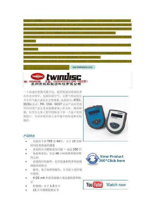
一个高速的便携式露点仪,提供快速的现场检查在许多应用中,包括压缩空气,天然气和高电压开关淬气露点或水分含量测量。
这款轻巧,ATEX ,IECEx 认证,FM ,CSA ,GOST 认证产品比其他任何同类产品让更多的测量每工作小时。
硬质耐磨,但符合人体工程学的情况下和一个易于使用的接口,可以在恶劣的工业环境中的舒适和实际操作。
产品特点∙ 在低压下从T95至-60℃,小于15分钟时间反复快速的测量∙ 更高的压力测量成为可能 - 高达350巴 ∙ 电池寿命长:长达48小时的典型使用费用之间∙ 直观的应用套件,允许快速和简单的连接到您的采样点∙ 耐用,易于处理和操作:专为在工业环境中使用∙ 4-20 mA 外部设备输入变送器校准和验证∙ 轻量级:小于1.5公斤 ∙13点可溯源校准证书MDM300的MDM300采样选项MDM300 MDM300要获得最佳性能,它是为您的测量点有适当的样品调节至关重要。