EMCCloudBoost磁盘阵列扩展盘架安装指引-戴尔易安信
- 格式:pdf
- 大小:1.51 MB
- 文档页数:28

DELL服务器磁盘阵列的扩容这里我们讨论服务器硬盘空间不足时,我们有什么方法可以扩充原有虚拟磁盘的空间,而无需删除上面的数据。
简介我们可通过扩充容量和/ 或改变RAID 级别的方式来重新配置联机虚拟磁盘。
注:跨接式虚拟磁盘(如RAID 10、50 和60)无法重新配置。
注:重新配置虚拟磁盘时一般会对磁盘性能有所影响,直到重新配置完成后为止。
联机容量扩充(OCE) 可通过两种方法实现。
∙如果磁盘组中只有一个虚拟磁盘,而且还有可用空间可供使用,则可在可用空间的范围内扩充虚拟磁盘的容量。
∙如果已创建虚拟磁盘,但虚拟磁盘使用的空间未达到该磁盘组大小的上限,则剩有可用空间通过Replace Member (更换成员)功能使用较大的磁盘更换磁盘组的物理磁盘时也可以获得可用空间。
虚拟磁盘的容量也可以通过执行OCE 操作来增加物理磁盘的数量进行扩充。
RAID 级别迁移(RLM) 是指更改虚拟磁盘的RAID 级别。
RLM 和OCE 可同时实现,这样虚拟磁盘可同时更改RAID 级别并增加容量。
完成RLM/OCE 操作后,不需要重新引导。
要查看RLM/OCE 操作可行性列表,请参阅下表。
源RAID 级别列表示执行RLM/OCE 操作之前的虚拟磁盘RAID 级别,目标RAID 级别列表示操作完成后的RAID 级别。
注:如果控制器包含的虚拟磁盘数目已达最大值,则不能再对任何虚拟磁盘进行RAID 级别迁移或容量扩充。
注:控制器将所有正在进行RLM/OCE 操作的虚拟磁盘的写入高速缓存策略更改为直写式,直到RLM/OCE 完成。
RAID级别迁移:下面,我们来演示一下两种情形下磁盘的扩容:联机容量扩充(OCE)实验的情景是:有一台R620服务器,两个硬盘驱动器。
Drive C:是RAID1的阵列,安装操作系统;Drive D:是10GB的RAID1阵列,装有数据文件。
如图:我们重启服务器,按CTRL-R进入PERC BIOS 管理界面查看一下RAID的配置:其中10GB的虚拟磁盘建立在一个总容量278GB的RAID1阵列上,该阵列还留有268GB的剩余空间。
Cisco Nexus 9504Switch Configuration Guide for Dell EMC SC Series andDell PS Series SANsAbstractThis document illustrates how to configure the Cisco® Nexus® 9504chassis with Dell EMC™ SC Series or Dell PS Series storage using DellEMC best practices.July 2018RevisionsRevisionsDate DescriptionJune 2016 Initial releaseJuly 2018 Combined steps for PS Series and SC Series storageThe information in this publication is provided “as is.” Dell Inc. makes no representations or warranties of any kind with re spect to the information in this publication, and specifically disclaims implied warranties of merchantability or fitness for a particular purpose.Use, copying, and distribution of any software described in this publication requires an applicable software license.© 2016–2018 Dell Inc. or its subsidiaries. All Rights Reserved. Dell, EMC, Dell EMC and other trademarks are trademarks of Dell Inc. or its subsidiaries. Other trademarks may be trademarks of their respective owners.Dell believes the information in this document is accurate as of its publication date. The information is subject to change without notice.Table of contentsTable of contents Revisions (2)1Introduction (4)1.1Document conventions (4)1.2Audience (4)1.3Switch details (4)1.4Cabling diagram (5)1.4.1PS Series cabling diagram (5)1.4.2SC Series cabling diagram (6)2Dell EMC recommended switch configuration (7)2.1Hardware configuration (7)2.2Delete startup configuration (7)2.3Run basic system configuration (8)2.4Enable Jumbo frames (9)2.5Enable LLDP (9)2.6Disable Data Center Bridging (9)2.7Enable link-level flow control (802.3x) (10)2.8Configure portfast on edge ports (10)2.9Enable switch ports (10)2.10Save configuration (10)A Technical support and resources (11)A.1Related resources (11)1 IntroductionThis document illustrates how to configure a Cisco® Nexus® 9504 chassis for use with Dell EMC™ SC Seriesor Dell™ PS Series storage using Dell EMC best practices. The recommended configuration when using asingle chassis is to configure two I/O modules.1.1 Document conventionsTable 1 lists the formatting conventions used in this document.Document conventionsItem Convention ExampleCode samples Monospace System configuration has been modified.Parameters Italic Dell(profile-name)#Command-line commands Bold OS#show versionBold, italic, brackets <vlan-id>Command-line user-suppliedvariables1.2 AudienceThis switch configuration guide describes an optimal configuration following Dell EMC best practices for anSC Series or PS Series iSCSI SAN and is intended for storage or network administrators and deploymentpersonnel.1.3 Switch detailsTable 2 provides an overview of the switch configuration.Cisco Nexus 9504Switch vendor CiscoSwitch model Nexus 9504Switch NX-OS 7.0(3)I1(2)Note: For proper functionality, the switch must be at the NX-OS version shown in Table 2 before proceedingwith this configuration. Using previous NX-OS versions may have unpredictable results.Note: The latest NX-OS updates and documentation can be found at: . This site requires alogin credential.1.4 Cabling diagramRefer to one of the following cabling sections that is applicable to your storage system: PS Series (section1.4.1) or SC Series (section 1.4.2).1.4.1 PS Series cabling diagramThe cabling diagram shown in Figure 1 represents the Dell EMC recommended method for deploying serversand PS Series storage arrays.PS Series cabling diagram1.4.2 SC Series cabling diagramThe cabling diagram shown in Figure 2 represents the Dell EMC recommended method for deploying serversand SC Series storage arrays.SC Series cabling diagram2 Dell EMC recommended switch configurationThe steps in this section show how to configure a single Cisco Nexus 9504 chassis with two I/O modules thatare installed in slot 1 and slot 2.Note: The configuration steps in this section are only recommended when the switch is used as a dedicatedSAN for iSCSI traffic (not shared with LAN traffic).2.1 Hardware configurationNote: Do not connect any server NIC or storage controller cables to the switch before performing thefollowing configuration steps.1. Power on the chassis.2. Connect a serial cable to the active supervisor management port.3. Using PuTTY or another terminal utility, open a serial connection session to the switch.4. Open the terminal emulator and configure it to use the serial port (COM1, COM2). Configure serialcommunications for 9600 N, 8, 1, and no flow control.5. Perform all CLI steps in sections 2.2 to 2.10.6. Connect all server NIC and storage controller cables to the switch. See section 1.4 for examplecabling diagrams.2.2 Delete startup configurationNote: This example assumes a switch at its default configuration settings. Using the write erase commandsets the startup configuration file to its default settings. Always back up your configuration settings prior toperforming any configuration changes.switch#write eraseWarning: This command will erase the startup-configurationDo you wish to proceed anyway ? (y/n) [n] yswitch# reloadThis command will reboot the systemDo you want to continue? (y/n) [n] yNote: The switch will reboot.2.3 Run basic system configurationThe following steps use the setup utility to configure connectivity for basic management of the system.After the switch fully reboots, the following prompts appear:Abort Power On Auto Provisioning and continue with normal setup ?(yes/no)[n]: y---- System Admin Account Setup ----Do you want to enforce secure password standard (yes/no): yesEnter the password for "admin": <password>Confirm the password for "admin": <password>---- Basic System Configuration Dialog VDC: 1 ----This setup utility will guide you through the basic configuration ofthe system. Setup configures only enough connectivity for managementof the system.Please register Cisco Nexus9000 Family devices promptly with yoursupplier. Failure to register may affect response times for initialservice calls. Nexus9000 devices must be registered to receiveentitled support services.Press Enter at anytime to skip a dialog. Use ctrl-c at anytimeto skip the remaining dialogs.Would you like to enter the basic configuration dialog (yes/no): yesCreate another login account (yes/no) [n]: nConfigure read-only SNMP community string (yes/no) [n]: nConfigure read-write SNMP community string (yes/no) [n]: nEnter the switch name : <switch name>Continue with Out-of-band (mgmt0) management configuration? (yes/no) [y]: yMgmt0 IPv4 address : <IP address>Mgmt0 IPv4 netmask : <netmask>Configure the default gateway? (yes/no) [y]: yIPv4 address of the default gateway : <gateway>Configure advanced IP options? (yes/no) [n]:nEnable the telnet service? (yes/no) [n]: yEnable the ssh service? (yes/no) [y]: nConfigure the ntp server? (yes/no) [n]: nConfigure default interface layer (L3/L2) [L2]: L2Configure default switchport interface state (shut/noshut) [shut]: shutConfigure CoPP system profile (strict/moderate/lenient/dense/skip) [strict]:skip The following configuration will be applied:<Your settings displayed here>Would you like to edit the configuration? (yes/no) [n]: nUse this configuration and save it? (yes/no) [y]: y[########################################] 100%Copy complete.Log in to the switch using the credentials you created.Note: You must perform port configurations for each individual port that is connected to a storage controller ora host server interface port, or you can specify a range of ports to configure. This example assumes all 48ports on linecard modules 1 and 2.2.4 Enable Jumbo framesswitch#configureswitch(config)#system jumbomtu 9216switch(config)#interface ethernet 1/1-48 , ethernet 2/1-48switch(config-if-range)#mtu 9216switch(config-if-range)#exitNote: By default, Data Center Bridging (DCB) is enabled. This document provides steps to disable DCB insection 2.6. Perform all operations during a maintenance window due to the temporary loss of communicationbetween host servers and storage arrays that may occur.2.5 Enable LLDPswitch(config)#feature lldpswitch(config)#interface ethernet 1/1-48 , ethernet 2/1-48switch(config-if-range)#lldp receiveswitch(config-if-range)#lldp transmitswitch(config-if-range)#exitswitch(config)#exit2.6 Disable Data Center BridgingAll steps in this section are required to properly disable Data Center Bridging (DCB). When upgrading fromprevious firmware versions to version 7.0(3)I1(2), DCB must be disabled.switch# configureswitch(config)#lldp tlv-select dcbxpswitch(config)#copy running-config startup-configswitch(config)#no lldp tlv-select dcbxpswitch(config)#exitswitch#copy running-config startup-configNote: The prior steps are required due to Cisco bug number, “CSCuo63486 LLDP - link err-disabled uponr eload when dcbx tlv is disabled”.2.7 Enable link-level flow control (802.3x)Perform this step for each individual port that is connected to a storage controller or a host server interfaceport, or specify a range of ports to configure.switch#configureswitch(config)#interface ethernet 1/1-48 , ethernet 2/1-48switch(config-if-range)#priority-flow-control mode offswitch(config-if-range)#flowcontrol send offswitch(config-if-range)#flowcontrol receive onswitch(config-if-range)#exit2.8 Configure portfast on edge portsswitch(config)#interface ethernet 1/1-48 , ethernet 2/1-48switch(config-if-range)#spanning-tree port type edgeWarning: edge port type (portfast) should only be enabled on ports connected toa single host. Connecting hubs, concentrators, switches, bridges, etc… to thisinterface when edge port type (portfast) is enabled, can cause temporarybridging loops. Use with CAUTION.Edge Port Type (Portfast) will be configured in 96 interfaces due to the rangecommend but will only have effect when the interfaces are in a non-trunkingmode.switch(config-if-range)#exit2.9 Enable switch portsThe following example enables a range of ports. If preferred, enable individual ports as needed.switch(config)# interface ethernet 1/1-48 , ethernet 2/1-48switch(config-if-range)# shutdownswitch(config-if-range)# no shutdownswitch (config-if-range)# exit2.10 Save configurationswitch#copy running-config startup-configswitch#reloadTechnical support and resourcesA Technical support and resources/support is focused on meeting customer needs with proven services and support.Storage Solutions Technical Documents provides expertise that helps to ensure customer success on DellEMC storage platforms.A.1 Related resourcesSee the following referenced or recommended Dell publications:•Dell PS Series Configuration Guide•Dell EMC Storage Compatibility Matrix11 Cisco Nexus 9504 Switch Configuration Guide for Dell EMC SC Series and Dell PS Series SANs | SCG3251。
Dell EMC Data Domain Hardware Features and Specifications Guide版本 6.2302-004-902修订版 02版权所有© 2018 Dell Inc. 或其子公司。
保留所有权利。
发布日期: 2018年 12 月戴尔确信本出版物在发布之日内容准确无误。
本出版物中的信息可随时更改而不另行通知。
本出版物的内容按“原样”提供。
戴尔对本出版物的内容不提供任何形式的陈述或担保,明确拒绝对有特定目的的适销性或适用性进行默示担保。
使用、复制或分发本出版物所描述的任何戴尔软件都要有相应的软件许可证。
Dell、EMC 和其他商标为 Dell Inc. 或其子公司的商标。
其他商标可能是其各自所有者的资产。
中国印刷。
易安信电脑系统(中国)有限公司中国北京朝阳区霄云路 38 号现代汽车大厦 15 层邮编:100027电话:(8610)8438 6000 传真:(8610)8453 8174 售前服务热线:400 650 6006/zh-cn/index.htm2Data Domain Hardware Features and Specifications Guide6.2913DD220017DD2200 系统功能 (18)DD2200 系统规格 (18)DD2200 存储容量.......................................................................................19前面板........................................................................................................20磁盘驱动器....................................................................................20前端 LED 指示灯............................................................................20后面板.........................................................................................................21电源单元........................................................................................21板载接口和 LED.. (22)I/O 模块和插槽分配 (24)FC I/O 模块选项............................................................................24以太网 I/O 模块选项......................................................................24内部系统组件..............................................................................................24冷却风扇. (25)DIMM 模块 (25)DD250027DD2500 系统功能 (28)DD2500 系统规格 (28)DD2500 存储容量.......................................................................................29前面板........................................................................................................30磁盘驱动器....................................................................................30前端 LED 指示灯............................................................................30后面板.........................................................................................................31电源单元........................................................................................31板载接口和 LED.. (32)I/O 模块和插槽分配 (33)FC I/O 模块选项............................................................................33以太网 I/O 模块选项......................................................................33内部系统组件..............................................................................................33冷却风扇. (34)DIMM 模块 (34)DD330035DD3300 系统功能 (36)DD3300 系统规格 (36)DD3300 存储容量.......................................................................................38前面板........................................................................................................38左侧控制面板.................................................................................39右侧控制面板.................................................................................41正面磁盘........................................................................................43服务标签. (43)图表第1章第2章第3章目录Data Domain Hardware Features and Specifications Guide 6.2 3后面板...........................................................................................44后面板........................................................................................................49产品序列号标签 (PSNT)................................................................51后端 SSD. (51)NIC 指示灯....................................................................................52电源指示灯 (52)DD420055DD4200 系统功能 (56)DD4200 系统规格 (57)DD4200 存储容量.......................................................................................58前面板........................................................................................................58电源单元........................................................................................59交流电源扩展模块.........................................................................59冷却风扇........................................................................................60固态驱动器....................................................................................60前端 LED 指示灯............................................................................60后面板.. (63)I/O 模块 LED.................................................................................63管理模块和接口.. (63)I/O 模块和插槽分配...................................................................................65插槽添加规则................................................................................65内部系统组件. (67)DIMM 模块 (67)DD450069DD4500 系统功能 (70)DD4500 系统规格 (71)DD4500 存储容量.......................................................................................72前面板........................................................................................................72电源单元........................................................................................73交流电源扩展模块..........................................................................73冷却风扇........................................................................................74固态驱动器....................................................................................74前端 LED 指示灯............................................................................74后面板 (77)I/O 模块 LED.................................................................................77管理模块和接口.. (77)I/O 模块和插槽分配....................................................................................79插槽添加规则.................................................................................79内部系统组件. (81)DIMM 模块 (81)DD630083DD6300 系统功能 (84)DD6300 系统规格 (84)DD6300 存储容量 (85)DD6300 前面板..........................................................................................86前端 LED 指示灯............................................................................87后面板.. (88)DD6300 后端固态驱动器...............................................................88背面 LED 指示灯. (88)I/O 模块 (91)第4章第5章第6章目录4Data Domain Hardware Features and Specifications Guide 6.2I/O 模块填充规则..........................................................................92内部系统组件.............................................................................................94DIMM 概述....................................................................................94DD680097DD6800 系统功能.......................................................................................98DD6800 系统规格.......................................................................................99DD6800 存储容量.......................................................................................99DD6800 前面板.........................................................................................100前端 LED 指示灯..........................................................................100后面板.......................................................................................................102背面 LED 指示灯..........................................................................102I/O 模块....................................................................................................105I/O 模块填充规则.........................................................................106内部系统组件............................................................................................108DIMM 概述...................................................................................108DD7200111DD7200 系统功能......................................................................................112DD7200 系统规格......................................................................................113DD7200 存储容量......................................................................................114前面板.......................................................................................................114电源单元.......................................................................................115交流电源扩展模块.........................................................................115冷却风扇.......................................................................................116固态驱动器...................................................................................116前端 LED 指示灯...........................................................................116后面板.......................................................................................................119I/O 模块 LED................................................................................119管理模块和接口............................................................................119I/O 模块和插槽分配...................................................................................121插槽添加规则................................................................................121内部系统组件............................................................................................123DIMM 模块...................................................................................123DD9300125DD9300 系统功能.....................................................................................126DD9300 系统规格......................................................................................127DD9300 存储容量......................................................................................127DD9300 前面板.........................................................................................128前端 LED 指示灯..........................................................................128后面板.......................................................................................................130背面 LED 指示灯..........................................................................130I/O 模块....................................................................................................133I/O 模块填充规则.........................................................................134内部系统组件............................................................................................136DIMM 概述...................................................................................136DD9500139系统功能 (140)系统规格....................................................................................................141DD9500 存储容量. (142)前面板.......................................................................................................144第7章第8章第9章第10章目录Data Domain Hardware Features and Specifications Guide 6.2 5前端 LED 指示灯...........................................................................144固态驱动器...................................................................................147后面板.......................................................................................................148电源单元......................................................................................148管理模块......................................................................................149背面 LED 指示灯..........................................................................150可用 I/O 模块................................................................................151以太网 I/O 模块选项....................................................................152光纤通道 I/O 模块........................................................................152SAS I/O 模块...............................................................................152I/O 模块插槽分配......................................................................................152插槽添加规则...............................................................................154内部系统组件.. (155)DIMM 模块...................................................................................157冷却风扇.. (157)DD9800159DD9800 系统功能.....................................................................................160DD9800 系统规格......................................................................................161DD9800 存储容量.....................................................................................162DD9800 前面板.........................................................................................164前端 LED 指示灯..........................................................................164固态驱动器...................................................................................167后面板.......................................................................................................168电源单元......................................................................................168管理模块......................................................................................169背面 LED 指示灯...........................................................................170可用 I/O 模块................................................................................171以太网 I/O 模块选项.....................................................................172光纤通道 I/O 模块 (172)SAS I/O 模块................................................................................172I/O 模块插槽分配......................................................................................172插槽添加规则...............................................................................174内部系统组件.. (175)DIMM 模块...................................................................................177冷却风扇 (177)ES30179ES30 概述.................................................................................................180ES30 现场要求..........................................................................................180ES30 硬件规格..........................................................................................181前面板.......................................................................................................181后面板.......................................................................................................183端口. (185)DS60187DS60 概述.................................................................................................188DS60 现场要求..........................................................................................188DS60 硬件规格..........................................................................................189DS60 前面板 ............................................................................................190后面板.......................................................................................................191磁盘存储模块内部 .....................................................................................191扩展盘架缆线.. (195)第11章第12章第13章目录6Data Domain Hardware Features and Specifications Guide 6.2端口 (196)FS15197FS15 SSD 驱动器概述...............................................................................198现场要求...................................................................................................198FS15 硬件规格...........................................................................................199FS15 前面板.............................................................................................200后面板.......................................................................................................201状态 LED.. (204)第14章目录Data Domain Hardware Features and Specifications Guide 6.27目录8Data Domain Hardware Features and Specifications Guide6.2前面板组件.................................................................................................................20磁盘 LED 和系统 LED.................................................................................................20显示亮起的系统电源 LED 的挡板................................................................................21机箱背面的功能部件...................................................................................................21电源单元 LED.............................................................................................................22板载接口和 LED..........................................................................................................22SP 模块系统俯视图....................................................................................................25已卸下空气导管的 SP 模块的俯视图..........................................................................25前面板组件.................................................................................................................30磁盘 LED 和系统 LED.................................................................................................30显示亮起的系统电源 LED 的挡板................................................................................31机箱背面的功能部件...................................................................................................31电源单元 LED.............................................................................................................32板载接口和 LED..........................................................................................................32SP 模块系统俯视图.....................................................................................................34已卸下空气导管的 SP 模块的俯视图...........................................................................34前面板........................................................................................................................39左侧控制面板.............................................................................................................40右侧控制面板..............................................................................................................42磁盘 LED 指示灯.........................................................................................................43服务标签.....................................................................................................................44后面板........................................................................................................................442 个 10 GbE 模块........................................................................................................454 个 16 Gbps FC 模块..................................................................................................46PSNT 位置..................................................................................................................46磁盘 LED 指示灯.........................................................................................................47NIC 指示灯..................................................................................................................47电源 LED 指示灯.........................................................................................................48后面板........................................................................................................................492 个 10 GbE 模块........................................................................................................504 个 16 Gbps FC 模块.................................................................................................50PSNT 位置..................................................................................................................51磁盘 LED 指示灯.........................................................................................................51NIC 指示灯.................................................................................................................52电源 LED 指示灯.........................................................................................................53前面板组件.................................................................................................................59系统 LED 指示灯.........................................................................................................60系统 LED 图例标签......................................................................................................61电源 LED.....................................................................................................................61风扇和 SSD LED.........................................................................................................62机箱背面的功能部件...................................................................................................63管理模块上的接口......................................................................................................64已卸下 SP 盖板的 SP 模块的俯视图...........................................................................67前面板组件.................................................................................................................73系统 LED 指示灯.........................................................................................................74系统 LED 图例标签.....................................................................................................75电源 LED....................................................................................................................75风扇和 SSD LED.........................................................................................................76机箱背面的功能部件...................................................................................................77管理模块上的接口.......................................................................................................78已卸下 SP 盖板的 SP 模块的俯视图............................................................................81前端 LED 指示灯.........................................................................................................87背面 LED 指示灯 (88)1234567891011121314151617181920212223242526272829303132333435363738394041424344454647484950515253图Data Domain Hardware Features and Specifications Guide 6.2 9I/O 模块电源/服务 LED 位置......................................................................................90板载网络端口 LED.......................................................................................................91I/O 模块插槽编号........................................................................................................91CPU 和内存的位置.....................................................................................................94前端 LED 指示灯........................................................................................................101背面 LED 指示灯.......................................................................................................102I/O 模块电源/服务 LED 位置....................................................................................104板载网络端口 LED.....................................................................................................105I/O 模块插槽编号......................................................................................................105CPU 和内存的位置....................................................................................................108前面板组件................................................................................................................115系统 LED 指示灯........................................................................................................116系统 LED 图例标签.....................................................................................................117电源 LED....................................................................................................................117风扇和 SSD LED........................................................................................................118机箱背面的功能部件..................................................................................................119管理模块上的接口.....................................................................................................120已卸下 SP 盖板的 SP 模块的俯视图..........................................................................123前端 LED 指示灯.......................................................................................................129背面 LED 指示灯.......................................................................................................130I/O 模块电源/服务 LED 位置.....................................................................................132板载网络端口 LED.....................................................................................................133I/O 模块插槽编号......................................................................................................133CPU 和内存的位置....................................................................................................136前面板组件................................................................................................................144服务 LED...................................................................................................................145电源按钮...................................................................................................................146前端 LED...................................................................................................................146SSD 驱动器...............................................................................................................147机箱背面的功能部件.................................................................................................148序列号标签位置.........................................................................................................148四个电源...................................................................................................................149管理模块...................................................................................................................1491000BaseT 以太网端口.............................................................................................150后端 LED 指示灯.......................................................................................................150电源 LED....................................................................................................................151NVRAM 和 I/O 模块的位置.......................................................................................153SP 模块 ....................................................................................................................156释放内存扩展板 ........................................................................................................156打开风扇托架............................................................................................................157前面板组件................................................................................................................164服务 LED...................................................................................................................165电源按钮...................................................................................................................166前端 LED...................................................................................................................166SSD 驱动器...............................................................................................................167机箱背面的功能部件.................................................................................................168序列号标签位置.........................................................................................................168四个电源...................................................................................................................169管理模块...................................................................................................................1691000BaseT 以太网端口..............................................................................................170后端 LED 指示灯.......................................................................................................170电源 LED....................................................................................................................171NVRAM 和 I/O 模块的位置........................................................................................173SP 模块 ....................................................................................................................176释放内存扩展板 ........................................................................................................176打开风扇托架. (17754555657585960616263646566676869707172737475767778798081828384858687888990919293949596979899100101102103104105106107108109)图10Data Domain Hardware Features and Specifications Guide 6.2。
Table of ContentsGet the power of Hadoop faster, with less risk 2What is your business goal? 2Dell EMC Ready Bundle for Cloudera Hadoop 3Configuration details 3Why Dell EMC for Hadoop? 4Complete your solution with Dell EMC Services and financing 5Dell EMC Professional Services 5Dell EMC Financial Services 5Find out more today 6Dell EMC Ready Bundle for Cloudera HadoopAn end-to-end Hadoop system, designed to address data analytics requirements, reduce costs and optimize performanceLeverage anend-to-end solutionReduce development costsOptimize performance Get the power of Hadoop faster, with less riskUnlike traditional systems, Hadoop enables multiple types of analytic workloads to runon the same data, at the same time, at massive scale on industry-standard hardware Cloudera’s Distribution of Hadoop (CDH) includes Apache® Hadoop and additional key open source projects to ensure you get the most out of Hadoop and your data, and it's engineered to meet the highest enterprise standards for stability and reliabilityDespite these tantalizing benefits, many organizations struggle — either to begin their data analytics journey or to make Hadoop projects successful once they’ve begunThey are often impeded by a lack of Hadoop expertise and end up spending too much time and effort on the front-end work before they can get to the results of a fully operational solutionExpertise and infrastructure matter when building a Hadoop environment That’s whyDell EMC has teamed up with industry leaders such as Cloudera®, Intel® and Syncsort® to remove the uncertainty and barriers that may be holding you back from deploying Hadoop Cost-effective, future-ready Dell EMC Ready Bundles for Cloudera Hadoop are comprehensive and easy-to-implement turnkey Hadoop solutions that help you efficiently harness the Hadoop platform and the power of data analytics to drive competitive advantageWhat is your business goal?The use cases for Hadoop are very diverse, but there are common patterns across industries and verticalsThis is just a sampling of possible use cases using the Dell EMC Ready Bundle for Cloudera HadoopOperational efficiency use casesDell EMC warehouse augmentation Log aggregation and analytics Dual storage and active archiveReduces total cost of ownership (TCO) and increasesreturn on investment (ROI)Secures your enterprise Reduces TCO and eases compliance• Offload extract, transform, load (ETL) workloads • Reduce licensing costs• Enhance data accessibility• Enable better data exploration and analytics • Manage performance more effectively • Prevent security breaches and threats• Detect operational anomalies• Increase infrastructure efficiency and automation• Lower data storage costs while maintainingaccessibility• Ease compliance and reporting• Streamline inquiry processes• Enjoy business operations improvementBusiness transformation use casesMarketing Finance Healthcare Pharmaceutical ManufacturingAnticipating customer needs Reducing risk and detecting fraud Improving patient care and reducingcosts Ensuring regulatory compliance andvalidationAchieving continuous processimprovement• Customer 360 insight• Customer retention• Customer segmentation • Customer loyalty• New product/service launch • Credit scoring• Customer analytics• Fraud detection• Risk management• Sarbanes-Oxley Act (SOX)compliance• Quality of care• Patient safety• Risk mitigation• Fraud detection• Claims management• Biomedical analytics• Stability and shelf life• Primary research• FDA compliancemanufacturing• Product quality• Customer insight• Demand forecasting•Improved operationsDell EMC Ready Bundle for Cloudera HadoopDell EMC Ready Bundle for Cloudera Hadoop is an integrated Hadoop system, designed to address data analytics requirements, reduce costs and optimize performanceSince 2011, Dell EMC and Cloudera have built validated solutions to help customers speed time to insights With our deep roots in data analytics solutions and Hadoop — and other leading partners in data analytics — Dell EMC has the expertise, tools and solutions needed to drive successful, flexible and scalable Hadoop deploymentsConfiguration detailsDell EMC Ready Bundles for Cloudera Hadoop offer a variety of configurations to meet your needs 1Dell EMC Cloudera Hadoop solution on PowerEdge R730XD ServerDell EMC Cloudera Hadoop solution on PowerEdge FX2 ServerDell EMC Cloudera Syncsort ETL offload Hadoop solution on PowerEdge R730XD Server Dell EMC Cloudera Syncsort ETL offload Hadoop solution on PowerEdge FC630 Server Dell EMC QuickStart for Cloudera HadoopUse cases Active archive/customer 360-degree Active archive/customer 360-degree ETL offload ETL offloadTesting and proofs of concept (POCs)Sizing Scales from 5 to 252 nodes, 3 8PBScales from 5 to 252 nodes, 3 8PBScales from 5 to 252 nodes, 3 8PB Scales from 5 to 252 nodes, 3 8PB 48TBSoftwareCloudera Enterprise OpenManage/iDRAC with Lifecycle Controller Cloudera Enterprise OpenManage/iDRAC with Lifecycle Controller Cloudera Enterprise Syncsort DMX-h and SILQ™Cloudera Enterprise Syncsort DMX-h and SILQCloudera Basic Edition OpenManage/iDRAC with Lifecycle Controller Pod network2 x Networking S4048 10GbE pod switches 1 x S3048 iDRAC switch 2 x Networking S4048 10GbE pod switches 1 x S3048 iDRAC switch 2 x Networking S4048 10GbE pod switches 1 x S3048 iDRAC switch 2 x Networking S4048 10GbE pod switches 1 x S3048 iDRAC switch Networking S3048-ON switchNetworking S4048-ON switchCluster network 2 x Networking S6000 40GbE cluster switches 2 x Networking S6000 40GbE cluster switches 2 x Networking S6000 40GbE cluster switches 2 x Networking S6000 40GbE cluster switches Infrastructure nodes1 x PowerEdge R630 Server admin node3 x PowerEdge R730XD Server name nodes1 x PowerEdge R730XD Server edge node 1 x PowerEdge R630 Server admin node3 x PowerEdge R730XD Server name nodes1 x PowerEdge R730XD Server edge node 1 x PowerEdge R630 Server admin node3 x PowerEdge R730XD Server name nodes1 x PowerEdge R730XD Server edge node 1 x PowerEdge FC630 Server admin node 3 x PowerEdge FC630 Server name nodes 1 x PowerEdge FC630 Server edge node2 x PowerEdge R730XD ServersWorker nodes10 x PowerEdgeR730XD Servers with 3 5" Drives — 48TB or 10 x PowerEdgeR730XD Servers with 2 5" Drives — 24TB10 x PowerEdge FC630 Servers10 x PowerEdge FD332 Storage — 32TB10 x PowerEdgeR730XD Servers with 3 5" Drives — 48TB or 10 x PowerEdgeR730XD Servers with 2 5" Drives — 24TB10 x PowerEdge FC630 Servers10 x PowerEdge FD332 Storage — 32TB3 x PowerEdge R730XD Servers1T he quantity and configurationDell EMC PowerEdge R730 Server : Impressive processor performance, a large memory footprint, extensive I/O (input/output) options and a choice of dense, high-performance storage or low-cost, high-capacity storageDell EMC PowerEdge FX2 Server : Modular server, storage and networking blocks are neatly combined in a compact, converged 2U rack chassis to redefine data center agility Dell EMC Networking S4048-ON 10/40GbE : T op-of-rack, high-density 1U switch with forty-eight 10GbE uplinks It offers ultra-low-latency and line-rate performance that is optimized for data centersDell EMC FC630 PowerEdge Server nodes : The 2-socket, half-width 1U workhorse server blocks are ideal for a wide variety of business applicationsDell EMC FD332 Storage : Flexible, high-density, half-width 1U storage modules enable you to rapidly scale direct attached storage (DAS)The Dell EMC Ready Bundle for Cloudera Hadoop Services includes:5• Onsite hardware and Operating System (OS) deployment services via Dell EMC ProDeploy• Dell EMC Cloudera Accelerator Services : Best practice guidance, hands-on labs,roadmap planning and knowledge transfer so you can get from install to full productivity, with the skills and knowledge to get the greatest value from your big data solution • Dell EMC Cloudera Hadoop Health Check Services : Reviews your current datatechnologies and processes, and makes recommendations for Cloudera tools, testing and operational practices• Dell EMC Consulting Services for Hadoop, including software installation and configuration, data migration and Microsoft ® Azure ® integration • Hardware and software support services via Dell EMC ProSupportWhy Dell EMC for Hadoop?The combination of Dell and EMC brings together two industry-leading companies with strong reputations for value and innovation And just to underscore that we are a technology leader, we've attained incredible leadership positions in some of the biggest and largest growth categories in the IT infrastructure business — and that means you can confidently source all your IT needs from one provider • #1 converged infrastructure 6• #1 in traditional and all-flash storage 7• #1 virtualized data center infrastructure 8• #1 secure business-class laptop 8• #1 cloud IT infrastructure 9•#1 server virtualization and cloud systems management software (VMware ®)10MetaScaleAchieved ROI in just 3 months 2T exas Advanced Computing Center (TACC)Gained up to 50X performance improvement 3Dell EMC40% increased automation of standard sales reports60% faster response times for prescriptive and predictive analysis 42D ell EMC case study, "Accelerating big data ROI with Hadoop ," April 20153D ell EMC case study video, "Dell EMC Drives Big Data Solutions at TACC ," November 2016 4D ell EMC case study, "Unlocking data's value for better insights and decisions ," May 2015 5A ll Dell EMC Services are standard in the US and Canada For all other regions, services are custom6I DC WW Quarterly ConvergedSystems Tracker, June 2016, Vendor Revenue—EMC FY 20157I DC WW Quarterly Enterprise Storage Systems Tracker, June 2016, Vendor Revenue—EMC CY 2015 8D ell EMC Annual Report, 2015 9I DC WW Quarterly Cloud ITInfrastructure Tracker, Q1 June 2016, Vendor Revenue—EMC FY 2015 10I DC WW Virtual Machine and Cloud System Market Shares 2015, July 2016Complete your solution with Dell EMC Services and financingDell EMC Professional ServicesSolutions customized for your needsDell EMC Hadoop Consulting is a best-in-class service delivered by certified Cloudera Hadoop experts to help you get the business value of data analytics using Hadoop The services include a data analytics assessment, workshop, testing, proofs of concept and production implementation These Hadoop experts help determine where Hadoop is a good fit for your organization They also help you build your own team of Hadoop experts through knowledge transfer at each stepSupport always on for youDell EMC ProSupport offers a single point of accountability from experts withsolution-specific training, along with premium hardware and software support available 24x7x365 ProSupport also includes collaborative support for Cloudera Enterprise software Additionally, ProSupport includes next-business-day onsite service withfour- and eight-hour parts and labor response options, and escalation management with customer-set severity level optionsDeployment assistance when you need itDell EMC offers a broad menu of installation and implementation services for Hadoop solutions through Dell EMC ProDeploy Dell EMC Services include onsite hardware and software installation, optional rack integration at a Dell EMC facility and validation of the installed solution Dell EMC takes care of the complete project management, from order drop to your acceptanceFor more information, visit Dell com/ServiceDescriptionsDell EMC Financial ServicesLet the wealth of leasing and financing options from Dell EMC Financial Services help you find opportunities when your organization faces decisions regarding capital expenditures, operating expenditures and cash flowDell EMC offers a wide range of payment options to make it easier than ever to meet your needsLearn more about Dell EMC Financial Services“We’ve completelyredesigned how we capture, store and provision data with the new Dell Hadoop cluster We can gather larger amounts of data, and our analysts and statisticians can mine that data in ways they couldn’t before ”11T ony Giordano, ExecutiveVice President of theT echnology Solutions Group,Merkle, United States“Addressing exhausted enterprise data capacity can cost up to $800,000 per terabyte of data But with Hadoop’s extreme scalability, adding terabytes can cost as little as $5,000 using MetaScale’s big data appliances based on Dell PowerEdge Servers ”12Ankur Gupta, General Manager, MetaScale,United States11D ell EMC case study, "A powerful new foundation for creating customer campaigns ," May 201512D ell EMC case study, "Accelerating big data ROI with Hadoop ," April 2015Find out more todayDon’t wait to harness the benefits of Cloudera Hadoop on a purpose-built solutiondesigned from the ground up to address data analytics requirements, reduce developmentcosts and optimize performance for deep data mining and analytics Contact your DellEMC representative to find out more todayCopyright © 2017 Dell Inc or its subsidiaries All Rights Reserved Dell, EMC, and other trademarks are trademarks of Dell Inc or its subsidiariesOther trademarks may be the property of their respective owners Published in the USA 02/17 Family guide DELL-EMC-FG-HADOOP-101Apache® and Hadoop® are either registered trademarks or trademarks of the Apache Software Foundation in the United States and/or other countries Cloudera® is a trademark or trade dress of Cloudera Intel® is a trademark of Intel Corporation in the U S and other countries Syncsort® and SILQ TM are the property of Syncsort in the United States and/or other countries Microsoft® and Azure® are a registered trademarks or trademarks of Microsoft Corporation in the United States and/or other countries VMware® is a registered trademark or trademark of VMware, Inc in the United States and/or other jurisdictions。
Dell EMC PowerVault ME4 Series存储系统部署指南注意、小心和警告:“注意”表示帮助您更好地使用该产品的重要信息。
:“小心”表示可能会损坏硬件或导致数据丢失,并告诉您如何避免此类问题。
:“警告”表示可能会导致财产损失、人身伤害甚至死亡。
© 2018 – 2021 Dell Inc. 或其子公司。
保留所有权利。
Dell、EMC 和其他商标是 Dell Inc. 或其附属机构的商标。
其他商标可能是其各自所有者的商标。
章 1: 开始之前 (6)打开机柜的包装 (6)安全守则 (7)安全处理 (7)安全操作 (8)电器安全 (8)机架系统安全预防措施 (8)安装核对表 (9)计划安装 (9)准备安装 (10)准备站点和主机服务器 (10)必需工具 (10)机架式安装要求 (10)磁盘驱动器模块 (11)2U 机箱中的驱动器托架模块 (11)驱动器状态指示灯 (12)空白驱动器托架模块 (12)5U 机柜中的 DDIC (12)使用 DDIC 填充盘位 (13)章 2: 将机柜安装到机架中 (15)机架式导轨套件 (15)安装 2U 机柜 (15)安装 2U 机柜前挡板 (16)安装 5U84 机柜 (16)连接可选的扩展机柜 (17)扩展机柜的电缆要求 (18)章 3: 连接管理网络 (20)章 4: 通过线缆将主机服务器连接到存储系统 (21)布线注意事项 (21)将机柜连接到主机 (21)CNC 技术 (21)光纤通道协议 (22)iSCSI 协议 (22)SAS 协议 (23)主机连接 (24)16 Gb 光纤通道主机连接 (24)10 GbE iSCSI 主机连接 (24)10Gbase-T 主机连接 (24)12 Gb HD mini-SAS 主机连接 (24)连接直连配置 (24)单控制器模块配置 (25)目录3章 5: 连接电源电缆并启动存储系统 (29)电源电缆连接 (29)章 6: 执行系统和存储设置 (31)记录存储系统信息 (31)使用指导式设置 (31)Web 浏览器要求和设置 (31)访问 PowerVault Manager (31)Update firmware(更新固件) (32)使用 PowerVault Manager Welcome 面板中的指导式设置 (32)章 7: 执行主机设置 (40)主机系统要求 (40)关于多路径配置 (40)Windows 主机 (40)配置具有 FC HBA 的 Windows 主机 (40)配置具有 iSCSI 网络适配器的 Windows 主机 (42)配置具有 SAS HBA 的 Windows 主机 (45)Linux 主机 (47)配置具有 FC HBA 的 Linux 主机 (47)配置具有 iSCSI 网络适配器的 Linux 主机 (48)适用于 Linux 的 SAS 主机服务器配置 (51)VMware ESXi 主机 (53)适用于 VMware ESXi 的光纤通道主机服务器配置 (53)适用于 VMware ESXi 的 iSCSI 主机服务器配置 (55)适用于 VMware ESXi 的 SAS 主机服务器配置 (57)Citrix XenServer 主机 (59)适用于 Citrix XenServer 的光纤通道主机服务器配置 (59)适用于 Citrix XenServer 的 iSCSI 主机服务器配置 (61)适用于 Citrix XenServer 的 SAS 主机服务器配置 (64)章 8: 故障排除和解决问题 (66)找到服务标签 (66)操作员 (Ops) 面板 LED (66)2U 机柜 Ops 面板 (66)5U 机柜 Ops 面板 (67)初始启动问题 (68)2U 机柜 LED (70)5U 机柜 LED (72)模块 LED (74)2U 机柜故障排除 (75)5U 机柜故障排除 (77)故障隔离方法 (77)执行基本步骤的可用选项 (78)执行基本步骤 (78)如果机柜未初始化 (79)更正机柜 ID (79)4目录处理硬件故障 (80)附录 A: 复制布线 (83)将两个存储系统连接到复制卷 (83)主机端口和复制 (83)复制布线示例 (84)用于复制的单控制器模块配置 (84)配置双控制器模块以用于复制 (84)隔离复制故障 (87)复制设置的诊断步骤 (88)附录 B: 用于 FC/iSCSI 端口的 SFP+ 收发器 (90)附录 C: 系统信息工作表 (92)附录 D: 使用 CLI 端口和串行线缆设置网络端口 IP 地址 (95)Mini-USB 设备连接 (97)Microsoft Windows 驱动程序 (98)Linux 驱动程序 (99)目录5开始之前本文档介绍 Dell EMC PowerVault ME4 Series 存储系统的初始硬件设置。
EMC存储系统安装配置手册目录第1章概述_________________________________________________________________ 61.1编写目的______________________________________________________________________ 6 1.2参考文档______________________________________________________________________ 7第2章存储硬件安装_________________________________________________________ 82.1EMC CX3中端磁盘阵列安装配置________________________________________________ 8第3章存储软件安装配置_____________________________________________________ 93.1整体说明______________________________________________________________________ 93.2IBM AIX平台软件安装__________________________________________________________ 93.2.1IBM pSeries 安装需求____________________________________________________________ 93.2.2ODM安装_______________________________________________________________________ 113.2.3PowerPath的安装 _______________________________________________________________ 163.2.3.1PowerPath5.0.0安装需求_______________________________________________________ 163.2.3.2PowerPath5.0.0安装流程_______________________________________________________ 163.2.4Navisphere Agent/Cli的安装_____________________________________________________ 193.2.4.1安装需求____________________________________________________________________ 193.2.4.2安装流程____________________________________________________________________ 193.2.5HACMP相关设置 ________________________________________________________________ 233.2.5.1提示:______________________________________________________________________ 233.2.5.2Set emcpowerreset in HACMP_________________________________________________ 233.2.5.3Add “cfgscsi_id” to HACMP(for CX3) ___________________________________________ 233.2.6常用命令 ________________________________________________________________________ 253.2.7IBM AIX主机识别PowerPath管理的设备___________________________________________ 263.3Redhat Linux平台软件安装____________________________________________________ 273.3.1PowerPath安装 _________________________________________________________________ 273.3.1.1安装需求____________________________________________________________________ 273.3.1.2安装流程____________________________________________________________________ 283.3.2Navisphere Agent/Cli安装_______________________________________________________ 283.3.2.1安装需求____________________________________________________________________ 283.3.2.2安装流程____________________________________________________________________ 293.3.3Linux主机识别PowerPath管理的设备 _____________________________________________ 293.4Windows2003平台软件安装 ___________________________________________________ 303.4.1PowerPath安装 _________________________________________________________________ 303.4.1.1安装需求____________________________________________________________________ 303.4.1.2安装流程____________________________________________________________________ 303.4.2Navisphere Agent/Cli安装_______________________________________________________ 383.4.2.1安装需求____________________________________________________________________ 383.4.2.2安装流程____________________________________________________________________ 383.4.3Windows主机识别PowerPath管理的设备_________________________________________ 47 3.5HP-UX平台软件安装 __________________________________________________________ 493.5.1PowerPath的安装 _______________________________________________________________ 493.5.1.1PowerPath5.0.1安装需求_______________________________________________________ 493.5.1.2PowerPath5.0.0安装流程_______________________________________________________ 50 3.5.2Navisphere Agent/Cli的安装_____________________________________________________ 543.5.2.1安装需求____________________________________________________________________ 543.5.2.2安装流程____________________________________________________________________ 54 3.5.3HPUX基本连接和认盘操作 ________________________________________________________ 56 3.5.4HP-UX主机识别PowerPath管理的设备 ____________________________________________ 583.6在HPUX和MCSG中使用认到的磁盘 ___________________________________________ 59 3.6.1单机环境下使用到的磁盘 __________________________________________________________ 593.6.2在MC/SG中使用认到的盘,并在其它主机上IMPORT VG________________________________ 613.7PP在HPUX平台使用Clariion磁盘创建LVM注意事项:_________________________ 62 3.7.1设置PV TIMEOUT值为180 _______________________________________________________ 62 3.7.2设置LV参数BBR为NONE _______________________________________________________ 62 3.7.3LV Striping_____________________________________________________________________ 623.8CX3Storage Group配置______________________________________________________ 63第1章概述1.1 编写目的本文档描述了EMC CX3中端磁盘阵列、Brocade 48000光纤交换机的硬件安装及配置流程;IBM AIX、HP-UX、Linux、Windows等相关操作系统连接EMC磁盘阵列时主机端软件的安装以及配置流程。
Dell Storage CenterGabinete de expansión SCv300 y SCv320 Guía de introducciónModelo reglamentario: E03J/E04JTipo reglamentario: E03J001/E04J001Notas, precauciónes y advertenciasNOTA: Una NOTA señala información importante que lo ayuda a hacer un mejor uso de su producto.PRECAUCIÓN: Una PRECAUCIÓN indica un potencial daño al hardware o pérdida de datos y le informa cómo evitar el problema.ADVERTENCIA: Una señal de ADVERTENCIA indica la posibilidad de sufrir daño a la propiedad, heridas personales o la muerte.Copyright © 2017 Dell Inc. o sus subsidiarias. Todos los derechos reservados. Dell, EMC y otras marcas comerciales son marcas comerciales de Dell Inc. o sus subsidiarias. Puede que otras marcas comerciales sean marcas comerciales de sus respectivos propietarios.2017 - 08Rev. A00Configuración del Gabinete de expansiónAntes de configurar el Gabinete de expansión SCv300 y SCv320, tenga en cuenta las siguientes prácticas recomendadas.•Antes de conectar cables entre el sistema de almacenamiento y el Gabinete de expansión, etiquete físicamente todos los puertos y conectores.•Siempre siga procedimientos adecuados de encendido y apagado cuando realice ciclos de encendido en la red. Compruebe que los componentes de red críticos se encuentren en circuitos de alimentación diferentes.NOTA: Este producto está destinado para áreas de acceso restringido, tal como salas de equipos dedicadas o armario de equipos.ADVERTENCIA: Si se instala en un ensamblaje de bastidor cerrado o de unidades múltiples, es posible que la temperatura ambiente de funcionamiento del entorno del bastidor sea más alta que la temperatura ambiente del lugar. Por lo tanto, es importante instalar el equipo en un entorno compatible con la temperatura ambiente máxima (Tma) especificada por el fabricante.Otra información útilEs posible que para instalar el Gabinete de expansión, necesite la siguiente información adicional.NOTA: Consulte la información reglamentaria y de seguridad proporcionada con los componentes de Storage Center. La información de garantía está incluida en un documento separado.•La guía Guía de implementación del sistema de almacenamiento SCv3020 del Storage Center de Dell (Guía de implementación del sistema de almacenamiento Dell Storage Center SCv3000/SCv3020) proporciona información sobre el cableado de los componentes de hardware del sistema de almacenamiento y la configuración de un nuevo sistema de almacenamiento mediante Dell Storage Client.•En la guía Dell Storage Manager Administrator’s Guide (Guía del administrador de Dell Storage Manager) se describe cómo utilizar Dell Storage Manager para administrar sistemas Storage Center.Instalación y configuraciónAntes de comenzar la instalación, asegúrese de que el sitio que en el que desea instalar el Gabinete de expansión tiene alimentación estándar desde una fuente independiente o una unidad de distribución de alimentación del bastidor con un SAI.Desembalaje del equipo de Storage CenterDesembale el Gabinete de expansión e identifique los artículos incluidos en el envío.3Figura 1. Componentes del Gabinete de expansión SCv300 y SCv3201.Cables de alimentación2.Cables SAS3.Embellecedor frontal4.Documentación5.Gabinete de expansión6.Rieles de bastidor (2)Instalación del Gabinete de expansión en un bastidorInstale el Gabinete de expansión SCv300 y SCv320 en un bastidor.NOTA: Monte el Gabinete de expansión de manera que permita la expansión en el bastidor y evite que éste se convierta en demasiado pesado.1.Monte de los rieles siguiendo las instrucciones de seguridad y las instrucciones de instalación en bastidor proporcionadas con suGabinete de expansión.2.Determine dónde montar el Gabinete de expansión en el bastidor y marque la ubicación.3.Instale los rieles del bastidor en la zona marcada.4.Monte el chasis del Gabinete de expansión en los rieles.Figura 2. Monte el chasis del Gabinete de expansión en el bastidor.5.Fije el chasis del Gabinete de expansión al bastidor utilizando los tornillos de montaje.Para obtener más información sobre la instalación del Gabinete de expansión, póngase en contacto con Servicios de asistencia técnica de Dell.4Instalación del embellecedor frontalInstale el bisel en la parte delantera del Gabinete de expansión.1.Conecte el extremo derecho del bisel al Gabinete de expansión.Figura 3. Bisel frontal2.Introduzca el extremo izquierdo del bisel en la ranura de fijación hasta que el pestillo de liberación se asiente en su lugar.3.Fije el embellecedor con la cerradura.Conexión de los cables de alimentaciónConecte los cables de alimentación al Gabinete de expansión1.Antes de conectar los cables de alimentación, asegúrese de que los interruptores de alimentación en el Gabinete de expansiónse encuentran en la posición de apagado.2.Conecte los cables de alimentación a los sistemas de alimentación en el chasis del Gabinete de expansiónFigura 4. Cables de alimentación3.Fije cada cable de alimentación al chasis del Gabinete de expansión utilizando los fijadores liberadores de tensión.4.Conecte el otro extremo del cable de alimentación a una toma eléctrica con conexión a tierra o a otra fuente de alimentación,como por ejemplo un sistema de alimentación ininterrumpida (SAI) o una unidad de distribución de alimentación (PDU). Información NOM (solo para México)La información que se proporciona a continuación aparece en el dispositivo descrito en este documento, de conformidad con los requisitos de la Norma Oficial Mexicana (NOM):5Especificaciones técnicasEn las siguientes tablas se muestran las especificaciones técnicas de los Gabinetes de expansión SCv300 y SCv320.678。
Dell EMC Systems Management Tools And Documentation Installation GuideVersion 10.0.1Notes, cautions, and warningsA NOTE indicates important information that helps you make better use of your product.A CAUTION indicates either potential damage to hardware or loss of data and tells you how to avoidA WARNING indicates a potential for property damage, personal injury, or death.© 2010 - 2021 Dell Inc. or its subsidiaries. All rights reserved. Dell, EMC, and other trademarks are trademarks of Dell Inc. or its subsidiaries. Other trademarks may be trademarks of their respective owners.Chapter 1: About (4)OMSA Customer Survey (4)Managed system and management station (4)Systems Management Tools and Documentation software (5)Active Directory Snap-In (5)iDRAC Tools (5)Dell Lifecycle Controller (6)iDRAC Service Module (6)Chapter 2: Installing management station software on Microsoft Windows (7)Installing management station software on Microsoft Windows Server and Hyper-V Server (7)Installing management station software using the CLI mode (7)Uninstalling management station software using the CLI mode (8)Chapter 3: Installing management station software on supported Red Hat Enterprise LinuxServer and SUSE Linux Enterprise Server (9)Contents31AboutThe Systems Management Tools and Documentation Installation Guide provides an overview of the management station software and installation instructions for the same. For information on installing Server Administrator, see the Dell EMC Server Administrator Installation Guide in the Dell EMC Systems Management Tools and Documentation software.Systems Management softwareThe systems management image comprises of the three software's mentioned below:●Systems Management Tools and Documentation●Server Updates●Management ConsoleYou can download the free ISO image of the software's from /Support/Home.For information on systems that support systems management software, supported operating systems, and components, see Dell EMC OpenManage Systems Software Support Matrix at /OpenManageManualsTopics:•OMSA Customer Survey•Managed system and management station•Systems Management Tools and Documentation softwareOMSA Customer SurveySurvey link: https://.Dell Technologies is exclusively surveying OMSA customers, collecting feedback, and implementing suggestions. As a customer, the above link is available for you to take the survey at various phases of OMSA usage such as Windows or Linux based installation, while using the OMSA GUI and CLI, and VMware ESXi.Managed system and management stationDepending on the way, you use the systems management tools, you can classify the systems as:●Managed SystemA managed system is any system that is monitored and managed using Server Administrator or Management Console. AServer Administrator is one of the systems management tools on the Systems Management Tools and Documentation software. You can manage systems running Server Administrator locally or remotely through a supported web browser. For more information about Server Administrator, see the Server Administrator User's Guide on the Systems Management Tools and Documentation software.●Management StationA management station is a laptop, desktop, or server that you use to remotely manage one or more managed systems from acentral location. You can use the following tools:○Intelligent Platform Management Interface (IPMI) Utilities○Integrated Dell Remote Access Controller (iDRAC) tools○Server Administrator Web Server4AboutSystems Management Tools and Documentation softwareThe Systems Management Tools and Documentation software contains the systems management software. The systems management software helps you to manage the systems by monitoring the system components, diagnosing issues, notifying through alerts, and troubleshooting remotely. Systems management software is classified as managed system software and management station software.Managed system softwareThe following applications include the managed system software:●Server AdministratorServer Administrator provides comprehensive one-to-one in-band server managements solutions. You can manage a server locally and remotely using a web browser-based Graphical User Interface (GUI) and Command Line Interface (CLI).When you perform a fresh installation on a system running a 64-bit operating system, a 64-bit version of theManagement station softwareThe following applications include the management station software:Active Directory Snap-InThe Active Directory (AD) Snap-In utility provides an extension snap-in to the Microsoft Active Directory to manage AD objects specific to products on this software.iDRAC ToolsThe iDRAC console is a management station software that provides remote management capabilities for the systems. Youcan remotely connect to the iDRAC global hardware and access the RAC features by using a web browser or the RACADM Command Line Interface (CLI). RACADM CLI is the command-line user interface to the RAC.●RACADM—For more information, see RACADM●IPMI Tools—For more information, see IPMI ToolsYou can install RAC either on the managed system or on the management station.For information about installing RAC on the managed system, see the Server Administrator Installation Guide. For information about installing on the management station, see Installing Management Station Software on Windows. For more information about RAC, see the Remote Access Controller User's GuideFrom OpenManage 9.3, x86 BMC is not available. The BMC x64 version is a part of iDRAC tools.RACADMThe Dell Remote Access Controller Admin (RACADM) utility is a command-line tool that enables remote or local management of Dell Servers using the iDRAC. RACADM provides similar functionality to the iDRAC Graphical User Interface (GUI). The Dell EMC Chassis Management Controller (CMC) can be managed remotely with RACADM. RACADM commands can be run remotely from a management station and/or locally on the managed system. RACADM commands enable you to view the managed system information, perform power operations on the managed system, perform firmware updates, configure settings and more. Because RACADM is run from a command line interface (CLI), system administrators can create scripts that control and update Dell EMC systems in a one-to-many fashion.About5IPMI ToolsIntelligent Platform Management Interface (IPMI) tool is a utility for managing and configuring devices that support the Intelligent Platform Management Interface. IPMI is an open standard for monitoring, logging, recovery, inventory, and controlof hardware that is implemented independent of the main CPU, BIOS, and operating system. The IPMI tool program providesa simple command-line interface to this BMC. It features the ability to read the sensor data repository (SDR) and print sensor values, display the contents of the System Event Log (SEL), print Field Replaceable Unit (FRU) inventory information, read and set LAN configuration parameters, and perform remote chassis power control.This program lets you manage IPMI functions of either the local system, by using a kernel device driver, or a remote system, using IPMI V1.5 and IPMI v2.0.IPMI management of a local system interface requires a compatible IPMI kernel driver to be installed and configured. On Linux, the driver is called Open IPMI and it is included in standard distributions. On Solaris, the driver is called BMC and is includedin Solaris 10. On Windows, it communicates through WMI driver. Management of a remote station requires the IPMI-over-LAN interface to be enabled and configured. Depending on the particular requirements of each system it may be possible to enable the LAN interface using IPMI tool over the system interface.Dell Lifecycle ControllerDell EMC recommends using the Embedded Management, Integrated Dell Remote Access Controller 9 (iDRAC9) with Lifecycle Controller instead of Dell EMC Systems Build and Update Utility (SBUU). SBUU is replaced with Lifecycle Controller onyx4x generation of PowerEdge servers. iDRAC with Lifecycle Controller is an Embedded Systems Management application for operating system deployment and lifecycle management of PowerEdge servers. You can access Dell Lifecycle Controller by pressing <F10> during system boot up. The local GUI of iDRAC9 with Lifecycle Controller enables you to do the following in a pre-OS environment:●Hardware configuration●Operating system and hypervisor deployments●Hardware updates●Hardware diagnostics●Easy maintenance of PowerEdge serversThe Lifecycle Controller is embedded on all 13th and later generation of PowerEdge servers. No tools or downloads are required to use the capabilities of Lifecycle Controller.For more information, see the following documents available at /OpenManageManuals:●Dell Lifecycle Controller Version <Version Number> User's Guide●Dell Lifecycle Controller Remote Services Version <Version Number> Quick Start Guide●Dell Lifecycle Controller Web Services Interface Guide●Lifecycle Controller Integration Best PracticesiDRAC Service ModuleThe iDRAC Service Module is a lightweight optional software application that can be installed on a yx3x and later generation of PowerEdge servers. Using the iDRAC Service Module you can configure the features on the supported operating system. The iDRAC Service Module provides additional Server Management data to iDRAC and presents one-to-many consoles with access to Systems Management data through operating system interfaces.The iDRAC Service Module also complements the iDRAC interfaces such as the GUI, RACADM CLI, and WSMan with additional monitoring features. For more information, see iDRAC Service Module <Version Number> Installation Guide available at /Support/Home.6AboutInstalling management station software onMicrosoft Windows1.Log on with administrator privileges to the system on which you want to install the management station applications.2.Mount the Systems Management Tools and Documentation software onto the DVD drive or download the web installer.You can download the web installer from /Support/Home .3.Run autorun.exe .If you are using the DVD to install, select the management station application that you want to install, and then Install .4.Follow the instructions in the Install Wizard.To install Server Administrator and iDRAC command line tools together, install Server Administrator without the Topics:•Installing management station software on Microsoft Windows Server and Hyper-V ServerInstalling management station software on Microsoft Windows Server and Hyper-V ServerWindows Server or Hyper-V Server operating system does not support a user interface (UI) based installation of the software components. Install the software in CLI mode on Server Core. For more information about Server Core, see the Microsoftwebsite.Log in as a built-in Administrator to install systems management software on Windows Server and Windows clientInstalling management station software using the CLI modeRun the Command Prompt as an administrator to successfully perform tasks using the CLI mode.To install the iDRAC Tools, launch the MSI file using the command:●msiexec /i iDRACTools_x64.msiOn the Systems Management Tools and Documentation software:The iDRACTools_x64.msi file is at SYSMGMT\ManagementStation\windows\iDRACToolsx64.iDRAC tools provide local and remote management capabilities for system that is equipped with iDRAC.To install Active Directory Snap-In, launch the MSI file using the command:●msiexec /i ADSnapIn_x64.msiOn the Systems Management Tools and Documentation software:The ADSnapIn_x64.msi file is at SYSMGMT\ManagementStation\windows\ADSnapInx64.To install the localized version of the management station software, at the command prompt type the following: msiexec / I <management_station_software>.msi TRANSFORMS= <languauge_transform>.mst2Installing management station software on Microsoft Windows 7Replace <language_transform>.mst with the appropriate language file:1031.mst (German)1034.mst (Spanish)1036.mst (French)1041.mst (Japanese)2052.mst (Simplified Chinese)Uninstalling management station software using the CLI mode To uninstall management station software, run the commands as listed in the following table:Table 1. Commands to uninstall management station softwareManagement Station Software CommandiDRAC Tools msiexec /x iDRACTools_x64.msi(or)msiexec /x {769409B5-7D2E-43C8-8525-C3CB782C87B7}Active Directory Snap-in msiexec /x ADSnapIn_x64.msi(or)msiexec /x {C392A19F-8431-405F-85FE-B1112E3046E2}Systems Management msiexec /x SysMgmtx64.msi(or)msiexec /x {C7C2A436-93C9-4934-B841-2AA3D689E2F2}8Installing management station software on Microsoft Windows3 Installing management station software on supported Red Hat Enterprise Linux Serverand SUSE Linux Enterprise ServerOnly iDRAC tools are supported on the Red Hat Enterprise Linux and SUSE Linux Enterprise Server operating systems.On systems running Red Hat Enterprise Linux operating system, DVDs are automounted with the -noexec mount option. You cannot run any executable program from the DVD. Mount the DVD-ROM manually and then run the executable programs.To install iDRAC tools, go to the SYSMGMT/ManagementStation/linux directory and install the BMU RPM specific to the operating system.To install the latest version of iDRAC Tools, do the following:For IPMI:1.Uninstall the existing IPMI tool:a.Query the existing IPMI tool: rpm -qa | grep ipmitoolIf the IPMI tool is already installed, the query returns ipmitool-x.x.xx-x.x.xx.b.To uninstall the IPMI tool:●On systems running Red Hat Enterprise Linux 7.x and 8.x, type rpm –e ipmitool2.iDRACTOOLS\ipmitool\<OS> directory and then type rpm -ivh *.rpm.For RACADM:1.To install RACADM:a.Go to the directory, where the tar.gz of iDRACTools is downloaded.b.Run the tar -zxvf on the tar.gz to unzip the contents into the current directory.c.From the current directory, where you have extracted the files, go to /linux/rac folder.d.To install the RACADM binary, start the script install_racadm.sh.install_racadm.sh script.2.a.Run the command openssl version to find the openssl version installed in the Host operating system.b.Locate the openSSL libraries, which are present in the HOST operating system, for example, ls -l /usr/lib64/libssl*.c.Soft-link the library libssl.so using the ln -s command to the appropriate OpenSSL version present in the Hostoperating system, for example, ln -s /usr/lib64/libssl.so.<version> /usr/lib64/libssl.so.3.To uninstall RACADM, use the uninstall_racadm.sh script.Installing management station software on supported Red Hat Enterprise Linux Server and SUSE Linux Enterprise9Server。
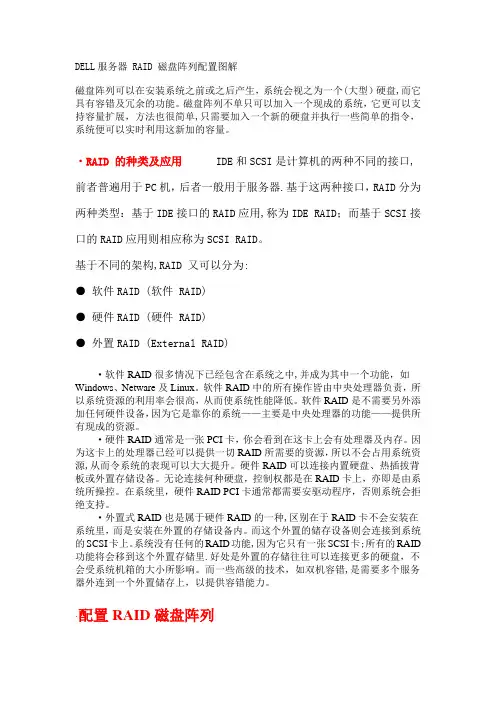
DELL服务器 RAID 磁盘阵列配置图解磁盘阵列可以在安装系统之前或之后产生,系统会视之为一个(大型)硬盘,而它具有容错及冗余的功能。
磁盘阵列不单只可以加入一个现成的系统,它更可以支持容量扩展,方法也很简单,只需要加入一个新的硬盘并执行一些简单的指令,系统便可以实时利用这新加的容量。
·RAID 的种类及应用IDE和SCSI是计算机的两种不同的接口,前者普遍用于PC机,后者一般用于服务器.基于这两种接口,RAID分为两种类型:基于IDE接口的RAID应用,称为IDE RAID;而基于SCSI接口的RAID应用则相应称为SCSI RAID。
基于不同的架构,RAID 又可以分为:● 软件RAID (软件 RAID)● 硬件RAID (硬件 RAID)● 外置RAID (External RAID)·软件RAID很多情况下已经包含在系统之中,并成为其中一个功能,如Windows、Netware及Linux。
软件RAID中的所有操作皆由中央处理器负责,所以系统资源的利用率会很高,从而使系统性能降低。
软件RAID是不需要另外添加任何硬件设备,因为它是靠你的系统——主要是中央处理器的功能——提供所有现成的资源。
·硬件RAID通常是一张PCI卡,你会看到在这卡上会有处理器及内存。
因为这卡上的处理器已经可以提供一切RAID所需要的资源,所以不会占用系统资源,从而令系统的表现可以大大提升。
硬件RAID可以连接内置硬盘、热插拔背板或外置存储设备。
无论连接何种硬盘,控制权都是在RAID卡上,亦即是由系统所操控。
在系统里,硬件RAID PCI卡通常都需要安驱动程序,否则系统会拒绝支持。
·外置式RAID也是属于硬件RAID的一种,区别在于RAID卡不会安装在系统里,而是安装在外置的存储设备内。
而这个外置的储存设备则会连接到系统的SCSI卡上。
系统没有任何的RAID功能,因为它只有一张SCSI卡;所有的RAID 功能将会移到这个外置存储里.好处是外置的存储往往可以连接更多的硬盘,不会受系统机箱的大小所影响。
Dell EMC PowerVault MD3860f 系列存储阵列部署指南注意、小心和警告:“注意”表示帮助您更好地使用该产品的重要信息。
:“小心”表示可能会损坏硬件或导致数据丢失,并告诉您如何避免此类问题。
:“警告”表示可能会导致财产损失、人身伤害甚至死亡。
© 2012 - 2018 Dell Inc. 或其子公司。
保留所有权利Dell、EMC 和其他商标为 Dell Inc. 或其子公司的商标。
其他商标均为其各自所有者的商标。
章 1: 简介 (5)系统要求 (5)存储阵列简介 (5)相关说明文件 (6)章 2: 硬件安装 (7)规划存储配置 (7)连接存储阵列 (7)配置 Dell EMC MD 系列存储阵列的光纤通道 (8)在 SAN 连接的存储阵列上配置光纤通道 (8)您可能需要的其他信息 (8)安装支持的光纤通道 HBA (8)在主机服务器上安装光纤通道 HBA (8)使用光纤通道交换机分区 (9)全局通用名称分区 (10)交换机分区准则 (10)在光纤通道交换机硬件上设置分区 (10)存储阵列布线 (10)冗余和非冗余布线 (10)SAN 连接布线 (10)SAN 连接布线示例 (11)远程复制布线示例 (12)混合环境 (13)PowerVault MD3060e 扩展柜布线 (14)使用新的 PowerVault Md3060e 扩展柜进行扩展 (16)章 3: 安装 MD Storage Manager (18)安装主机总线适配器和驱动程序 (18)图形化安装(推荐) (19)控制台安装 (19)无提示安装 (19)在 Windows 中进行无提示安装 (19)在 Linux 中进行无提示安装 (20)启用高级功能(可选) (20)升级 PowerVault MD Storage Manager (20)章 4: 安装后任务 (21)验证存储阵列查找 (21)初始设置任务 (21)章 5: 卸载 MD Storage Manager (23)从 Windows 中卸载 MD Storage Manager (23)从 Windows Server GUI 版本卸载 MD Storage Manager (23)目录3从 Windows Server Core 版本卸载 MD Storage Manager (23)从 Linux 中卸载 MD Storage Manager (24)章 6: Load balancing(负载平衡) (25)负载均衡策略 (25)带子集的轮询 (25)最少队列深度 (25)最少路径权重 (25)在 Linux 中设置负载平衡策略 (25)在 VMware 中设置负载平衡策略 (26)章 7: 附录—使用 SFP 模块和光纤电缆 (27)SFP 模块使用指南 (27)安装 SFP 模块 (27)卸下 SFP 模块 (28)光纤电缆使用指南 (28)安装光纤通道电缆 (28)卸下光纤通道电缆 (29)章 8: 附录—硬件布线妥善做法 (30)处理静电敏感组件 (30)远程复制的主机布线 (30)布线以提高性能 (30)给电缆贴标签 (30)章 9: 获得帮助 (31)联系戴尔 (31)找到 Dell EMC 系统服务标签 (31)4目录1简介本指南提供关于部署 Dell EMC PowerVault MD3860f 存储阵列的信息。
运行 SUSE Linux Enterprise Server 15 的 Dell EMC PowerEdge 系统安装说明和重要信息注、小心和警告注: “注”表示帮助您更好地使用该产品的重要信息。
小心: “小心”表示可能会损坏硬件或导致数据丢失,并说明如何避免此类问题。
警告: “警告”表示可能会造成财产损失、人身伤害甚至死亡。
© 2018 - 2019 Dell Inc. 或其子公司。
保留所有权利。
Dell、EMC 和其他商标是 Dell Inc. 或其附属机构的商标。
其他商标可能是其各自所有者的商标。
2019 - 06Rev. A021 概述 (4)系统配置要求 (4)操作系统架构 (4)内存 (4)引导盘大小 (4)检查预配置选项 (5)Dell EMC 预装操作系统程序包 (5)语言 (5)存储分区 (5)2 创建 SUSE Linux Enterprise Server 15 安装程序介质 (6)3 安装或重新安装 SUSE Linux Enterprise Server (7)安装之前的重要信息 (7)通过 Lifecycle Controller 安装 SUSE Linux Enterprise Server (7)在 iSCSI 存储上安装 SUSE Linux Enterprise Server (8)在启用 FCoE 的存储上安装 SUSE Linux Enterprise Server (8)附加设备驱动程序 (8)通过 SUSE 客户中心或 Repository Mirroring Tool 更新系统程序包 (9)4 获取帮助 (10)联系 Dell EMC (10)Linux 相关的说明文件 (10)说明文件资源 (10)下载驱动程序和固件 (12)说明文件反馈 (12)目录3概述SUSE Linux Enterprise Server 15 可用于 64 位 Intel 体系结构。
Dell EMC Boot Optimized Server Storage-S1用户指南9 2020注意、小心和警告:“注意”表示帮助您更好地使用该产品的重要信息。
:“小心”表示可能会损坏硬件或导致数据丢失,并告诉您如何避免此类问题。
:“警告”表示可能会导致财产损失、人身伤害甚至死亡。
© 2017 - 2020 Dell Inc. 或其子公司。
保留所有权利。
Dell、EMC 和其他商标是 Dell Inc. 或其附属机构的商标。
其他商标可能是其各自所有者的商标。
章 1: 概览 (5)支持的操作系统 (6)支持的 PowerEdge 系统 (6)BOSS-S1 卡规格 (7)支持的 M.2 驱动器 (7)BOSS-S1 控制器的管理应用程序 (7)更新 BOSS-S1 控制器 (8)更新 BOSS-S1 固件 (8)使用操作系统特定的 DUP 更新固件 (8)使用 Windows DUP 更新固件 (8)使用 Linux DUP 更新固件 (8)使用 UEFI Shell 更新固件 (9)使用 BOSS-S1 CLI 更新固件 (9)使用 Windows 更新固件 (9)使用 Linux 更新固件 (9)使用 HTTP 更新固件 (10)使用 Lifecycle Controller 更新固件 (10)相关说明文件 (10)章 2: 功能 (12)外部导入 (12)SMART 信息 (12)自动重建 (12)非 RAID 磁盘支持 (12)TRIM (13)快速初始化 (13)擦除物理磁盘 (13)章 3: 部署 BOSS-S1 卡 (14)卸下 BOSS-S1 卡 (14)将 M.2 BOSS 模块提离 BOSS-S1 卡 (15)在 BOSS-S1 卡上安装 M.2 SSD 模块 (16)安装 BOSS-S1 卡 (17)章 4: 驱动程序安装 (19)章 5: UEFI 或 HII RAID 配置实用程序 (20)进入 UEFI 配置公用程序 (20)退出 UEFI 配置公用程序 (20)进入 BOSS-S1 配置实用程序 (20)物理或虚拟磁盘信息 (21)物理磁盘信息 (21)虚拟磁盘信息 (21)虚拟磁盘导入 (21)目录3创建虚拟磁盘 (21)删除虚拟磁盘 (22)RAID 重建 (22)擦除物理磁盘 (22)控制器信息 (22)清除控制器配置 (22)章 6: BOSS-S1 CLI 命令 (23)在 Windows 中使用 CLI 命令 (23)从 Linux 中使用 CLI 命令 (23)在 ESXi 中使用 CLI 命令 (23)支持的 BOSS-S1 CLI 命令 (24)章 7: 故障处理 (25)在 VSphere 生命周期管理器中导入 BOSS ESXi CLI 离线捆绑包可能会失败 (25)从 Dell EMC 的自定义版本 6.7.x 升级到版本 7.0 时,BOSS ESXi CLI 软件包会失败 (25)当 BOSS-S1 控制器上具有现有的适配器密钥时,在未配置的驱动器上从 iDRAC 进行 M.2 驱动器固件更新失败 (26)BOSS-S1 控制器中未配置的驱动器对于具有现有的适配器密钥的操作系统安装不可用 (26)BOSS 的 ROM 版本在 iDRAC 界面中报告为固件版本 (26)BOSS-S1 控制器上 M.2 驱动器的固件更新失败 (26)在 Linux 中 BOSS-S1 CLI 显示未找到适配器错误 (26)LC 日志显示风扇不可用错误 (26)使用 iDRAC 或 LC 更新 BOSS-S1 控制器固件失败 (26)物理磁盘大小在 iDRAC 中未更新 (27)在 iDRAC 中缺失物理磁盘/虚拟磁盘 (27)HII 中的后台活动任务进度不报告实时状态 (27)虚拟磁盘状态将生成两次 (27)命名虚拟磁盘时的字符限制 (27)VMFS 数据存储在第 14 代 PowerEdge 系统(在 BOSS-S1 上已安装 VMware ESXi)上已禁用 (27)物理磁盘对操作系统不可见 (28)虚拟磁盘对操作系统不可见 (28)驱动器更换 (28)控制器更换 (28)控制器故障 (28)无法引导到插槽 1 中安装的 M.2 驱动器 (29)CLI 报告不支持的功能 (29)在 RAID 1 上安装 ESXi 失败 (29)系统无响应 (29)管理端口无响应 (29)章 8: 获得帮助 (30)联系 Dell EMC (30)说明文件反馈 (30)4目录概览BOSS-S1 是一种简单的 RAID 解决方案卡,专用于引导服务器的操作系统。
磁盘阵列安装终极图文教程一、准备工作:阵列必要:2个大小相同型号周期一致的硬盘(用于R0,R1,JOB模式)硬件工具:一个硬盘载体,用于母盘制作,主盘启动(可以用IDE/SATA硬盘,USB移动硬盘,大容量U盘)软件工具:HDTunePro,带WINPE的U盘启动盘,驱动精灵。
如果要新装系统,GHOST安装盘,硬装盘自选。
我本机已经有个WD 500G 的绿盘了,我目标是把500G 绿盘资料转到阵列R0 1TB上。
我购买了2个全新同型号的WD 500G 蓝盘来做这次演示!这个是我的绿盘2个全新硬盘二、安装组建篇1.硬件阵列的组建:阵列我以前就说过是主板带的硬盘模式而已。
组建硬件阵列第一步:接上2个全新的WD 500G 蓝盘。
第2步:进入主板BIOS设置界面,找到硬盘模式相关设置,设置完成保存退出重启!看到没有Storage Configuration,点击进入由于主板支持单独定义2组SATA硬盘1-4 5-6两组本次使用的主启动盘是SATA的原因在这里有些主板不能这样单独设置的话请使用其他介质!正确的设置BIOS 1-4 阵列模式5-6 IDE模式对应硬盘也要在主板相应的编号接口上插好哦搜集整理:电脑实用技巧&实用绿色破解软件电脑100 第3步:进入阵列参数设置阵列类型保存BIOS退出重启后将出现下面的画面记住按CRTL+F 这2个键进入设置!阵列功能主界面有4个选项:1.查看阵列。
2.组建功能。
3。
删除类 4.控制设置我们这里需要用到的是第2个:LD VIEW/LD DEFINE MENU 点进入出现如下界面如何创建阵列呢同学需要注意下面这里的提示:< CTRL+C > Define LD 这个就是创建阵列的操作界面了!!进入阵列创建模式的菜单操作指令最下面都有《上下》选择《空格》修改。
2个硬盘可以创建阵列0 、1、JBOD 这三个模式,通常我们选择RO R1 这2个JOB那个无视了,这个JBOD 模式等于2个硬盘“无缝焊接” 第一个装满了装第2个!!正确的RO 设置注意128K Y Y 2个下图搜集整理:电脑实用技巧&实用绿色破解软件电脑100 设置完成保存弹出一个界面这个界面说的是:要给这个阵列命名就再按Ctrl+Y 不需要名字的话就任意键下一步按照提示保存退出组建完成重启后提示是这样的(我取了个名字1TB )第4步安装系统首先说明这里安装如果使用常规手段必然导致的结果是系统不能识别阵列蓝屏!所以我们换个角度让系统识别阵列(就是如何在系统启动的时候就有驱动可用)接上原来的WD 绿盘插在SATA 5-6 这组上进BIOS 设置硬盘启动优先启动WD 绿盘搜集整理:电脑实用技巧&实用绿色破解软件电脑100 以上操作后进入绿盘上原来的WIN7 系统嘿嘿就会提示这个东西啦有同学以前装过完整驱动的话当然这个时候是可以加载到的,有同学没有装过会提示安装不成功怎么办呢!!看吧感谢驱动精灵驱动人生这2款超好用的软件驱动完整后阵列就可以看到了这里可以不用分区什么的,如何系统到阵列我们下面讲.(注意这里必须保证能在系统下看到阵列。
安装了 Microsoft ® Windows Server ® 故障时转移群集的 Dell|EMC AX4-5i iSCSI 存储阵列硬件安装与故障排除指南简介群集硬件的布线准备系统以进行群集故障排除群集数据表iSCSI 配置工作表注、注意和警告本说明文件中的信息如有更改,恕不另行通知。
© 2008 Dell Inc.。
版权所有,翻印必究。
未经 Dell Inc. 书面许可,严禁以任何形式进行复制。
本文中使用的商标:D e l l 、D E L L 徽标、PowerEdge 、PowerVault 和 OpenManage 是 Dell Inc. 的商标;Active Directory 、Microsoft 、Windows 、Windows Server 和 Windows NT 是 Microsoft Corporation 在美国和/或其它国家和地区的商标或注册商标;E M C 、Navisphere 和 PowerPath 是 EMC Corporation 的注册商标,且 MirrorView 、SAN Copy 和 SnapView 是 EMC Corporation 的商标。
本说明文件中述及的其它商标和产品名称是指拥有相应商标和产品名称的公司或其制造的产品。
Dell Inc. 对其它公司的商标和产品名称不拥有任何所有权。
2008 年 4 月 Rev A00注:“注”表示可以帮助您更好地使用计算机的重要信息。
注意:“注意”表示可能会损坏硬件或导致数据丢失,并告诉您如何避免此类问题。
警告:“警告”表示可能会导致财产损失、人身伤害甚至死亡。
返回目录页面群集硬件的布线安装了 Microsoft ® Windows Server ® 故障时转移群集的 Dell|EMC AX4-5i iSCSI 存储阵列硬件安装与故障排除指南鼠标、键盘和显示器的布线电源设备的布线公用网络和专用网络的群集布线存储系统的布线鼠标、键盘和显示器的布线在机架中安装群集配置时,必须安装转换盒,以将鼠标、键盘和显示器连接至节点。
EMC CloudBoost Disk Array Expansion Shelf版本 2.0安装指南P/N 302-002-517REV. 01版权所有© 2015 年 EMC Corporation。
保留所有权利。
中国印刷。
发布日期: 2015 年 12 月EMC 确信本出版物在发布之日内容准确无误。
本出版物中的信息可随时更改而不另行通知。
本出版物的内容按“原样”提供。
EMC CORPORATION 对本出版物的内容不提供任何形式的陈述或担保,明确拒绝对有特定目的的适销性或适用性进行默示担保。
EMC²、EMC 和 EMC 徽标是 EMC Corporation 在美国和其他国家/地区的注册商标或商标。
此处使用的所有其他商标均为其各自所有者的资产。
有关产品系列的最新法规文档,请访问 EMC 在线支持 (https://)。
易安信电脑系统(中国)有限公司中国北京朝阳区霄云路 38 号现代汽车大厦 15 层邮编:100027电话:(8610)8438 6000传真:(8610)8453 8174售前服务热线:400 650 6006网站:2EMC CloudBoost Disk Array Expansion Shelf2.0 安装指南57CloudBoostDAE 盘架安装概述9现场要求 (10)DAE 机箱 (10)前面板:磁盘 (10)后面板:电源/冷却模块和盘架控制器 (12)安装 DAE 盘架15扩展盘架缆线 (16)安全要求 (16)机架安装与缆线连接 (17)滑轨套件 (17)端口 (17)用缆线连接 DAE 盘架 (18)连接电源 (20)安装后的任务21将电源连接到 DAE 盘架 (22)验证 DAE 盘架安装 (24)《Disk Array Expansion Shelf Installation Guide 》(磁盘阵列扩展盘架安装指南)27DAE 硬件规格 (28)图表第 1 章第 2 章第 3 章附录 A 目录EMC CloudBoost Disk Array Expansion Shelf 2.0 安装指南3目录4EMC CloudBoost Disk Array Expansion Shelf2.0 安装指南DAE 前面板(挡板已卸下)..........................................................................................10前面板 LED 指示灯........................................................................................................11后面板:DAE 的完全相同的盘架控制器(控制器 B 位于控制器 A 上方)....................12后面板:电源模块(控制器 B 位于控制器 A 上方).....................................................12控制器 A LED 指示灯.....................................................................................................13CloudBoost 系统的缆线连接方式..................................................................................18盘架端口.......................................................................................................................18CloudBoost 系统,连接到 DAE 的第一条缆线...............................................................19CloudBoost 系统,连接到 DAE 的第二条缆线...............................................................19C14(左)和 C13(右)电源线....................................................................................20后面板:完全相同的盘架控制器(控制器 B 位于控制器 A 上方). (23)后面板:电源模块(控制器 B 位于控制器 A 上方) (23)123456789101112图EMC CloudBoost Disk Array Expansion Shelf 2.0 安装指南5图6EMC CloudBoost Disk Array Expansion Shelf2.0 安装指南DAE 现场要求................................................................................................................10磁盘存储模块正面显示的状态指示灯...........................................................................11磁盘存储模块背面显示的状态指示灯 ..........................................................................13HD-Mini-SAS 到 Mini-SAS 缆线部件号...........................................................................16DAE 滑轨套件 ...............................................................................................................17DAE 硬件规格. (28)123456表EMC CloudBoost Disk Array Expansion Shelf 2.0 安装指南7表8EMC CloudBoost Disk Array Expansion Shelf2.0 安装指南第 1 章CloudBoostDAE 盘架安装概述通过将磁盘阵列的扩展盘架添加到 EMC CloudBoost 系统,可以增加系统的存储容量。
有关更换 DAE 组件的说明,请参见https://中提供的相应文档。
您应当将任何印刷版的文档都视为可能已过时。
因此,在更换任何部分之前,请始终检查在线支持门户中是否有最新版本的必要文档。
l现场要求 (10)l DAE 机箱 (10)CloudBoostDAE 盘架安装概述9现场要求此表列出了 DAE 的现场要求。
请参见“DAE 硬件规格(第 28 页)”以了解硬件规格信息。
表 1 DAE 现场要求标准 19 英寸 4 柱机架中的垂直空间3U 。
切勿使用双柱机架。
请参见包装中的滑轨和安装文档以在机架中进行安装。
空调可处理最大 BTU/小时散热额定值的空调。
温度控制适当的温度控制,可使一小时内温度梯度(变化)不超过 30° C 。
前挡板间隙1.56 英寸(4.0 厘米)的未被阻塞的间隙。
后面板间隙5 英寸(12.7 厘米)的未被阻塞的间隙。
气流在密封或有多个装置的机架中,请确保装置具有足够的空气流动。
如果设备安装在封闭式机架(而不是开放式四柱机架)中,则前门和后门应当至少具有 65% 的开放区域以便于空气流动。
无论在开放式还是封闭式机架中,都应使用填充面板来防止热空气再循环。
机架设计和安装应当考虑设备的最高工作时环境温度,该值为 35° C 。
电源/接地两个单相交流电源插座及一个接地导体(安全接地)。
您必须为每条电源线提供安全的电气接地连接。
电压应该为 100-120 伏交流电压或200-240 伏交流电压;50 或 60 赫兹。
仅用于受最小 15 安过流保护器保护的分支电路。
将两条电源线插入到单独的分支电路电源中以实现冗余。
DAE 机箱本部分介绍了 DAE 盘架的前面板和后面板,以及 DAE 机箱正面和背面显示的状态指示灯。
前面板:磁盘在松开并卸下前面板上的卡入式挡板后,即可看到 15 个磁盘。
系统命令报告的磁盘编号范围为 1 到 15。
面向前面板时,磁盘 1 位于存储模块最左侧的插槽中,磁盘 15 位于最右侧的插槽中。
图 1 DAE 前面板(挡板已卸下)㽷㎞DAE 上的凸缘或金属薄板显示 0 到 14,但软件所引用的逻辑编号将是 1 到 15。
CloudBoostDAE 盘架安装概述10EMC CloudBoost Disk Array Expansion Shelf 2.0 安装指南CloudBoostDAE 盘架安装概述存储模块中的每个磁盘有两个 LED 指示灯。
当磁盘正常运行时,磁盘的活动状态 LED 指示灯会发出绿色亮光。
当磁盘发生故障时,磁盘故障 LED 指示灯会发出琥珀色亮光。
如果存储模块出现问题,存储模块故障指示灯将为琥珀色。
当盘架接通电源时,磁盘存储模块电源指示灯应亮起(呈蓝色)。
指示灯图 2 前面板 LED1.磁盘存储模块故障指示灯2.磁盘存储模块电源指示灯3.磁盘活动状态指示灯4.磁盘故障指示灯表 2 磁盘存储模块正面显示的状态指示灯CloudBoostDAE 盘架安装概述后面板:电源/冷却模块和盘架控制器为实现冗余,DAE 具有两个完全相同的电源/冷却模块和两个完全相同的盘架控制器,其摆放顺序正好相反。
上方)图 3 后面板:DAE 的完全相同的盘架控制器(控制器 B 位于控制器 A Array1.控制器 B2.控制器 B 的 LED 指示灯3.控制器 A4.控制器 A 的 LED 指示灯㽷㎞更换组件时,在将其卸除之前,请注意其方向。
将替换组件插入相同的位置。
控制器 A 的电源位于盘架底部,控制器 B 的电源位于盘架顶部。
上方)图 4 后面板:电源模块(控制器 B 位于控制器 A Array1.LED 指示灯:控制器 B:电源 LED、电源故障:琥珀色,风扇故障:琥珀色2.扩展(输出)12EMC CloudBoost Disk Array Expansion Shelf2.0 安装指南CloudBoostDAE 盘架安装概述3.主机(输入)4.存储模块地址5.电源(绿色)或故障(琥珀色)6.总线 ID7.主机链路处于活动状态8.扩展链路处于活动状态9.LED 指示灯:控制器 A:电源 LED、电源故障:琥珀色,风扇故障:琥珀色指示灯图 5 控制器 A LED表 3 磁盘存储模块背面显示的状态指示灯CloudBoostDAE 盘架安装概述*DAE 将使用一个电源和四个风扇中的三个继续运行。