Inspector-1000使用培训教材
- 格式:ppt
- 大小:3.53 MB
- 文档页数:46

ARCHITECT系统i1000标准操作检测程序1.仪器工作基本要求1.工作环境1.1仪器必须放置在水平地面1.2仪器必须远离热源物体或冷源物体,避免阳光直射1.3仪器放置必须有一定的周边空间1.4仪器电源尽量保持一直打开1.5仪器必须严格按保养和维护要求执行2. 操作干扰2.1运行过程中绝对不能切断电讯连接2.2在仪器运行请关注废物的装载情况2.3在仪器运行时确保所有运行模块的门和盖为关闭状态,除非仪器是在执行保养或诊断程序2.4如果主电源对SCC的供电被切断,请执行Shutdown程序3.缓冲液、试剂、标准品和质控品3.1必须使用雅培原厂生产的所有试剂,否则会对结果或系统产生严重的干扰和破坏3.2必须在标贴的效期内使用所有试剂3.3必须严格按照试剂说明书的要求保存和运输试剂3.4不得将不同批号的试剂混合使用4. 系统消耗品4.1不得反复使用或使用非雅培原厂生产的消耗品4.2持消耗品的清洁4.3必须在标贴的效期内使用4.4必须在原包装条件下保存5. 样品的准备5.1一般使用静脉采血,避免样品溶血5.2根据试剂说明书使用样品类型5.3根据试剂说明书保存和处理样品5.4如是冷冻样品,融解后必须彻底混匀,避免样品反复冻融5.5样品中如有颗粒物质必须离心驱除,注意溶血,脂血或黄疸血的可能干扰5.6按说明书要求提供用血量5.7避免样品产生气泡或泡沫5.8只有人源样品可用于检测仪器操作规程1.开机(Power on)-- 建议24小时开机1.1打开显示器电源→电脑主机SCC电源→等待显示器屏幕转到操作系统主界面1.2打开仪器PM电源,待仪器屏幕上运行模块与轨道模块的状态由离线→已停止1.3选择运行模块与轨道模块图标,选择启动,等待两者的状态由已停止→准备就绪,即可开始每日工作2.检查供应中心和试剂2.1供应→供应状态→检查各部分是否充足,是否需要更换,如需要,选择更新供应→更换→更新完成后→完成2.2试剂→试剂状态→检测试剂测试数是否充足,是否需要放置新试剂,如需要(可运行中更换),选择主界面上轨道模块准备就绪的图标→运行→模块开始初始化,完成后转为运行中,放置新试剂前,要先充分混匀磁性颗粒试剂,换上隔膜盖,按照不同颜色放在试剂架上,然后将试剂架推入轨道,仪器自动将试剂放入试剂盘中。

Inspector射线仪用户手册1导言“Inspector”射线仪是用于健康和安全方面的仪器,测量低水平的辐射。
它测量α、β、γ和x射线。
应用领域包括:●探测和测量表面污染●在接近放射性核素的地方,监测可能的辐射量●评估环境污染●探测稀有气体和其它低能量放射性核素“Inspector”如何测量辐射“Inspector”用一支盖革管-弥勒计数管来探测辐射。
每次当辐射通过盖革管时,盖革管产生一个脉冲电流并引起电离。
这样每一次脉冲都被电路探测到且记为一个计数。
“Inspector”按照您选择的模式来显示读数。
由于放射性的随机性,仪器检测到的计数每分钟都在变化。
取一段时间内的平均值更加精确,时间越长越精确。
参见第三章“总量/加权操作模式”的细节。
预防措施要使仪器保持良好状态,请小心使用和阅读下面内容:●不要将仪器接触放射性表面或材料,这样才不会污染“Inspector”。
如果怀疑被污染了,请更换粘在手册里的橡皮条。
●不要将仪器置于38°C的高温下,不要长时间将仪器暴晒在太阳下。
●不要弄湿仪器。
水会损坏电路板和盖革管的云母表面。
●不要将仪器置于微波炉里。
它不能测微波,所以会损坏仪器或微波炉。
●本仪器可能对无线频率,微波,静电乃至电磁场均有感应,但不能正常工作。
●如果想搁一段时间再用,可将电池取出,防止电池腐蚀。
●电量不足时请充好电。
2特点(请参考英文附图)“Inspector”测量α、β、γ和x射线。
经过优化设计的这种仪器能测量小的辐射变化,且对通常的放射性核素有高的灵敏度。
参见附录A“对通常的放射性核素的灵敏度”查看更多信息。
本章简单描述“Inspector”的功能。
“Inspector”计数电离事件而在液晶(LCD)上显示显示结果。
请用模式开关选择测量单位。
无论何时使用,每次红技术灯闪烁一次,就表示一个探测到一个计数(一个电离事件)。
显示(1)(请参考英文附图)液晶LCD根据模式设置显示不同指示值,功能操作和电池状况指示值(请参考英文附图)●数字显示(A)显示当前的辐射量。

涉外钻井工程英语培训教材目录A PRE-DRILLING PREPARATION钻前准备 4A1 Inspection for Road and Bridge conditions路桥监测 4 A2 Well site Arrangements井场布局A3 Equipment Inspection装备探伤A4 Movilization and rigging up设备搬迁与安装8A5 Preparation For Mud Instruments泥浆检测仪器的准备9 A6 Preparation of Fire Equipment 消防设施的准备10A7 Preparation of daily-used materials日常用料准备11A8 Transportation and communication交通与通信12A9 Electrical Equipment电器设备13A10 Auxiliary Equipment辅助设备14B DRILLING PROCEDURE钻井程序错误!未定义书签。
B1 Drilling Program钻井设计错误!未定义书签。
B2 Drilling Tool and Bit钻井工具及钻头21B3 Common Drilling Instruments And Drilling Parameters常用钻井仪表与参数27B4 Common Properties and Testing of Drilling Fluid常用钻井液性能及测试 32B5 Drill String Assembly钻具组合34B6 Instructions of Drilling Operation and IADC Report钻井指令及IADC报表38B7 Shifting and Inspecting交接班及检查40B8 The Daily Reports日常工作汇报45C WELL CONTROL井控错误!未定义书签。

Towa TS-1000 programming FRENCH ManualTowa FranceManuel Programmation TS10002-2-12 Arrangements (Articles liés) (35)2-3 Utilisateurs (38)2-3-1 Profils (38)2-3-2 Clefs (41)2-3-3 Vendeurs (42)2-4 Noms caisses (43)2-5 Libellés (43)2-6 Date (46)2-7 Suggestion du jour (46)2-7-1 Entrée du jour (47)2-7-2 Plat du jour (47)2-7-3 Dessert du jour (47)2-7-4 Menu programme (47)2.8 Clavier Alpha (47)3 Configurer (48)3.1 Paramètres niveau 1 (48)3.1.1 Ports d’impression (48)3.1.2 Anglais / Français (48)3.1.3 Clavier Alpha (48)3.1.4 Système de couleur (49)3.1.5 Graphisme situation actuel (50)3.1.6 Graphismes périodes (à définir) (50)3.2 Paramètres niveau 2 (50)3.2.1 Modes de fonctions (50)3.2.2 Modes de fonctions chiffrés (54)3.2.2.1 Général (54)3.2.2.2 Règlements (55)3.2.2.3 Périphériques (55)3.2.3 Formats d’impression (56)3.2.4 Etat d’impression résultats (56)3.2.5 Filtres historique (56)3.2.6 Outils disquette (56)3.2.6.1 Sauvegarde multi-disquette (56)3.2.6.2 Sauvegarde compressée (56)3.2.6.3 Restauration compressée (56)3.2.6.4 Restaure programmation compressée (56)3.2.6.5 Chargement Logo (57)3.2.6.6 Vider disquette (57)3.2.6.7 Nettoyage disquette (57)3.2.6.8 Nettoyage disquette (58)3.2.7 Happy hour (58)3.3 Paramètres niveau 3 (59)4 Edition (60)4-1 Lecture (60)4-2 Raz (60)4-3 Historique des ventes (60)4-3-1 Complète (60)4-3-2 Condensée (60)4-3-3 Non détaillée (60)4-3-4 Filtres historiques (60)5 Programmation avancée (61)5-1 Gestion des avoirs sur ticket restaurant avec code barre (61)5.2 Mode cafétéria (62)5.3 Compte avec détail jour par jour (62)5.4 Ticket direct (62)5.5 Table (62)5.6 Cuisine (62)5.7 Repas complet (63)This is a “Table of Contents preview” for quality assuranceThe full manual can be found at /estore/catalog/ We also offer free downloads, a free keyboard layout designer, cable diagrams, free help andsupport. : the biggest supplier of cash register and scale manuals on the net。
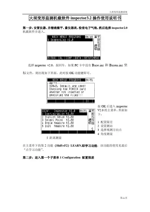
大坝变形监测机载软件inspector3.2操作使用说明书第一步:安置仪器,并精确整平,量仪器高,检查电子气泡,然后选择inspector2.0机载软件并进入。
选择inspector v2.0,按回车,如果PC卡中没有Base.ins和Basen.ins坐标文件,则出现如下界面,此时按OK功能键即可。
按OK后进入inspectorV2.0的主菜单,界面如下:1 配置限差2 设置测站3 选择观测方向点4 角度测量5 距离测量在主菜单下的第2功能(Shift+F2)LEARN,即学习功能,该功能的使用见最后“点学习功能”。
第二步:进入第一个子菜单1 Configuration 配置限差各项参数的含义如下:a.“CH No.”—测回数b.“ΔD ”—测距较差的限差c.“2C ”—2C值d.“Δ2C”—2C差互差的限差e.“GL ”—归零差的限差;g.“HzHc ”—测回较差h.“i ”—指标差i.“Δi ”—指标差互差j.“ VHc ”—竖直角较差k“Dist CN”—测距次数各项配置完成后,按CONT键确认并退出。
第三步:进入第2个子菜单 2 Station Setup 设置测站按F1(Stat.)进入测站设置,此时光标在第一行项,按F6(LIST)列表选择测站点名,光标自动跳到BS. Name项,按F6(LIST)列表选择定向点点名,完成后,按OK键,仪器将自动计算测站点到定向点的方位角,并显示在最后一行Hz0:上,你这时要记住该角度值,再按F2(Hz0),瞄准定向点后,将你所记住的角度输入到仪器上,仪器将以此方位角配置水平度盘,完成后按CONT键退出到上图界面,再按CONT键退到主菜单。
第四步:进入第3个子菜单 3 Select point 选择观测方向点测站点名定向点名Selected:被选择的点在坐标文件中的顺序号按F6(LIST)以从左到右的顺序依次选择要观测的方向点,选择完成后按CONT键退出。


Operating Instructions • Warning Information• Parts BreakdownAll rights reservedFAILURE TO OBSERVE THESE WARNINGS COULD RE S ULT IN IN J U R Y.THIS INSTRUCTION MAN U A L CON T AINS IM P OR T ANT SAFE T Y INFORMATION.READ THIS IN S TRUC T ION MANUAL CARE F UL L Y AND UN D ER S TAND ALL IN F OR M A T ION BE F ORE OP E R A T I NG THIS TOOL.• It is the responsibility of the owner to make sure all personnel read this manual prior to using this air tool. It is also the responsibility of the air tool owner to keep this manual intact and in a convenient location for all to see and read. If the manual or product labels are lost or not legible, contact Cornwell for replacements. If the operator is not fluent in English, the product and safety instructions shall be read to and discussed with the operator in the operator's native language by the purchaser/owner or his designee, making sure that the operator comprehends its contents.• Al w ays op e r a te, in s pect and main t ain this tool in ac c or d ance with Amer i c an Na t ion a l Stan d ardsIn s ti t ute Safe t y Code of Por t a b le Air Tools (ANSI B186.1) and any oth e r ap p li c a b le safe t y codes and reg u l a t ions.• For safety, top per f or m ance and max i m um du r a b il i t y of parts, op e r a te this tool at 90 psig: 6.2 bar max air pres s ure with 3/8" di a m e t er air sup p ly hose.• Always wear im p act-re s is t ant eye pro t ec t ion when op e r a t i ng or per f orm i ng main t e n ance on this tool (users and bystanders). • Al w ays wear hear i ng pro t ec t ion when us i ng this tool (users and bystanders). High sound levels can cause per m a n ent hear i ng loss. Use hear i ng pro t ec t ion as rec o m m end e d by your em p loy e r or OSHA reg u l a t ion.• K eep the tool in ef f i c ient op e r a t i ng con d i t ion.• Operators and main t e n ance per s on n el must be phys i c al l y able to han d le the bulk, weight and pow e r of this tool.Air un d er pres s ure can cause se v ere in j u r y. Nev e r di r ect air at your s elf or oth e rs. Al w ays turn off the air sup p ly, drain hose of air pres s ure and de t ach toolfrom air sup ply be f ore in s tall i ng, re m ov i ng or ad j ust i ng any ac c es s o r y on this tool, or be f ore per f orm i ng any main t e n ance on this tool. Fail u re to do so could re s ult in in j u r y. Whip hos e s can cause se r i o us in j u r y. Al w ays check for dam a ged, frayed or loose hos e s and fit t ings, and re p lace im m e d i a te l y. Do not use quick de t ach cou p lings at tool. See in s truc t ions for cor r ect set-up on page 4.Air powered tools can vi b rate during use. Vi b ra t ion, re p et i t ive mo t ions or un c om f ort a ble po s i t ions over ex t end e d pe r i o ds of time may be harm f ul to yourhands and arms. Dis c on t in u e use of tool if dis c om f ort, tin g ling feel i ng or pain oc c urs. Seek med i c al ad v ice be f ore re s um i ng use.• Slip p ing, tripping and/or falling while op e r a t i ng air tools can be a ma j or cause of se r i o us in j u r y or death. Be aware of ex c ess hose left on the walk i ng or work sur f ace.• Keep body work i ng stance bal a nced and firm. Do not over r each when op e r a t i ng the tool.• Anticipate and be alert for sud d en chang e s in mo t ion dur i ng start up and op e r a t ion of any pow e r tool.• Do not carry tool by the hose. Pro t ect the hose from sharp ob j ects and heat.• Tool shaft may continue to rotate briefly after throttle is released. Avoid direct contact with accessories during and after use. Gloves will reduce the risk of cuts or burns.• Keep away from rotating end of tool. Do not wear jewelry or loose clothing. Secure long hair. Scalping can occur if hair is not kept away from tool and accessories. Choking can occur if neckwear is not kept away from tool and accessories.• Note direction of rotation BEFORE operating tool. • Do not use (or modify) the tool for any other purpose than that for which it was designed without consulting the manufacturer's authorized representative.• Do not lu b ri c ate tools with flam m a b le or vol a t ile liq u ids such as ker o s ene, die s el or jet fuel. • This tool is not insulated against electric shock.• This tool must not be used in explosive atmospheres. • Servicing and repairs should only be made by anauthorized service center.• Do not force tool be y ond its rat e d capacity.• Use accessories recommended by Cornwell Tools.• Use only impact sockets and accessories on this tool. Do not use hand sockets and accessories.• Keep tool out of reach of children.• Do not remove any labels. Re p lace any damaged la b els.• Failure to heed these warnings may result in serious or fatal personal injury and/or property damage.WARNING: This product can expose you to chemicals including nickel, which is known to the State of California to cause cancer and birth defects or other reproductive harm. For more information go to .PARTS BREAKDOWN - CAT1000MRR / CAT1000MRRGOnly parts identified by part number above are available for purchase.HEAD KIT 354057CAT1000MRRRHK1238121110132122232425263031323334363738392728294342411415161718151519204689AIR SUPPLYTools operate on a wide range of air pressures. It is recommended that air pressure measures 90 psig at the tool with the trigger fully depressed and no load applied to the tool. Higher pressure (over 90 psig; 6.2 bar) raises performance beyond the rated capacity of the tool, which will shorten tool life and could cause injury.Always use clean, dry air. Dust, corrosive fumes and/or water in the air line will cause damage to the tool. Drain water from air lines and com-pressor prior to running tool. Clean the air inlet filter screen weekly. The recommended hookup procedure can be viewed in the above figure. The air inlet used for connecting air supply has standard 1/4" NPT. Line pressure should be increased to compensate for unusually long air hoses (over 25 feet). Minimum hose diameter should be 3/8" I.D. and fittings should have the same inside dimensions and be tightly secured.Ensure an accessible emergency shut off valve has been installed in the air supply line and make others aware of its location. LUBRICATIONLubricate the air motor daily with high quality air tool oil. If no air line oiler is used, run 1/2 oz. of oil through the tool. The oil can be squirted into the tool air inlet or into the hose at the nearest con-nection to the air supply, then run the tool. A rust inhibitive oil is acceptable for air tools.WARNING: After an air tool has been lubricated, oil will discharge through the exhaust port during the first few seconds of operation. The exhaust port must be covered with a towel before applying air pressure to prevent serious injury.OPERATIONThis ratchet is rated at 3/8" USS bolt size. Rat i ng must be down grad e d for spring U bolts, tie bolts, long cap screws, double depth nuts, badly rust e d conditions and spring fas t en e rs as they absorb much of the impact power. When possible, clamp or wedge the bolt to prevent springback. The reverse button is used to change the direction of the tool. When the button is turned to the left, the tool is in a for w ard or right hand direction. When the button is turned to the right, the direction is in reverse or left hand direction.NOTE: Actual torque on a fastener is directly related to joint hardness, tool speed, condition of socket and the time the tool is allowed to impact. Use the simplest possible tool-to-socket hook up. Every connection absorbs energy and reduces power.NOTE: Always turn off the air supply, drain hose of air pressure and detach tool from air supply before installing, removing or adjusting any part or accessory on this tool, or before performing any maintenance on this tool.Use only impact sockets and accessories on this tool. Do not use hand sockets and accessories.TROUBLESHOOTINGOther factors outside the tool may cause loss of power or erratic action. Reduced compressor output, excessive drain on the air line, moisture or restrictions in air pipes or the use of hose connections of improper size or poor conditions may reduce air supply. Grit or gum deposits in the tool may cut power and may be corrected by cleaning the air strainer and flushing out the tool with gum solvent oil or an equal mixture of SAE #10 and kerosene. If outside conditions are in order, disconnect tool from hose and take tool to your nearest authorized service center.WARRANTYCornwell Quality Tools Company (“Cornwell”) warrants this product against defects in material and workmanship for a period of ONE (1) YEAR from the date of original retail purchase. Subject to the conditions and limitations set forth below, Cornwell will, at its option, either repair or replace any part of the product(s) that proves defective by reason of improper workmanship or materials.This warranty does not cover any damage to this product that results from accident, abuse, misuse, natural or personal disaster, or any unauthorized disassembly, repair, or modification. Repairs, disassembly and modification are only authorized to be made by Cornwell or a Cornwell Authorized Warranty Center.WARRANTY SERVICEIn order to have your tool repaired, return the tool to any Cornwell Au t ho r ized Warranty Center, freight pre p aid. Please include a copy of your proof of pur c hase and a brief de s crip t ion of the prob l em. The tool will be inspected and if any part or parts are found to be de f ec t ive in ma t e r i a l or work m an s hip, they will be re p aired free of charge, and the re p aired tool will be re t urned to you freight pre p aid.EXCLUSIONS AND LIMITATIONSTHIS WARRANTY AND THE REMEDIES SET FORTH ABOVE ARE EXCLUSIVE AND IN LIEU OF ALL OTHER WARRANTIES, REMEDIES AND CONDITIONS, WHETHER ORAL OR WRITTEN, EXPRESS OR IMPLIED. CORNWELL SPECIFICALLY DISCLAIMS ANY AND ALL IMPLIED WARRANTIES, INCLUDING, TO THE EXTENT PERMITTED BY APPLICABLE LAW, ANY WARRANTIES OF MERCHANTABILITY AND FITNESS FOR A PARTICULAR PURPOSE. IF CORNWELL CANNOT LAWFULLY DISCLAIM IMPLIED WARRANTIES UNDER THIS LIMITED WARRANTY, ALL SUCH IMPLIED WARRANTIES ARE LIMITED IN DURATION TO THE DURATION OF THIS WARRANTY.IN NO EVENT SHALL CORNWELL BE LIABLE TO THE PURCHASER OR TO THE USER OF A CORNWELL PRODUCT FOR ANY SPECIAL, INCIDENTAL OR CONSEQUENTIAL DAMAGES BASED UPON BREACH OF WARRANTY, BREACH OF CONTRACT, NEGLIGENCE, TORT, OR ANY OTHER LEGAL THEORY. SUCH DAMAGES INCLUDE, WITHOUT LIMITATION, EXPENSES, LOST REVENUES, LOST SAVINGS, LOST PROFITS, OR ANY OTHER INCIDENTAL OR CONSEQUENTIAL DAMAGES ARISING FROM THE PURCHASE, USE OR INABILITY TO USE THE CORNWELL PRODUCT.Some states do not allow the exclusion or limitation of incidental or consequential damages or exclusions or limitation on the duration of implied warranties or conditions, so the above limitations or exclusions may not apply to you. This warranty gives you specific legal rights, and you may also have other rights that vary by state.Repair kits and replacement parts are available for many Cornwell products, regardless of whether or not the product is still covered by a warranty plan.Cornwell Quality Tools Company667 Seville Road • Wadsworth, OH 44281-1094。
INSPECTOR射线检测仪操作手册1.引言该产品是一种健康、平安的仪器,被普遍应用于检测低强度辐射。
它能够检测到α、β、γ三种射线。
其应用范围如下:·探测和检测表面污染·在有放射性核素的情形下,可监控可能的辐射方向·掩蔽对环境的污染·探测稀有气体和低能量放射性核检测器如何探测辐射该检测器运用盖革计数管来探测辐射。
每次射线穿过管子并引发电离时,盖革计数管会产生一脉冲电流。
每一个脉冲都是电子探测并进行运算。
探测器以你选择的模式显示计算:CPM,mR/hr,或共计。
在s1单位中,利用CPS和µsv/hr。
检测器探测出来的计数数字由于放射能的任意状态而每分钟都在转变。
以过去一段时刻内的平均值表示加倍准确,而且这段时刻越长数据越准确。
警告为了使检测器维持良好状态,要轻拿轻放,而且遵守以下标准:·不要由于接触放射性表面或材料而污染检测器。
若是疑心被污染,你能够用检测器提供的额外的带子替换后面标签上面和下面的橡皮带。
·不要将检测器放在100ºF(38℃)以上的高温中和长时刻在阳光下直晒。
·幸免潮湿。
水会损害电路和盖革计数管表面的云母涂层。
·幸免探测器薄片在阳光直射下;若是盖革计数管表面的云母涂层由于潮湿被磨损被损害,这将会阻碍数据读取。
·不要将检测器放入微波炉中。
检测器不能测量微波,如此做会损坏检测器和微波炉。
·幸免在无线电波频率、微波、静电和电磁波范围内利用;仪器在这一范围内可能比较灵敏,而且会运转不正常。
·假设超过一个月不用,将电池拿开,以避免造成电池的侵蚀破坏。
·若是电池指示器出此刻显示器上,请改换电池。
2.特性检测器能够测定α、β、γ和x射线。
用来探测辐射强度的微小转变,而且对通常的放射性核有很高的灵敏度。
这一节简单的介绍检测器的功能。
关于更多的如何利用检测器,请看第三章“操作”。
八年级(下)语文期末检测试题班级: 姓名:一、基础知识积累及运用(41分)1、下列句子中加点字书写和注音完全正确的一项是()(4分)A、哪知老境却如此颓(tuǐ)唐。
B、黑人义愤填鹰.(yīng)的酷暑就不会过去。
C、李石清愤概.(gài)地骂着黄省三。
D、现在绝非侈.(chǐ)谈冷静下来或服用渐进主义的镇静剂的时刻。
2、下列句子中加点的成语使用有误的一项是()(4分)A、自从父母离婚以后,他每次回到家,总有一种茫然若失....的感觉。
B、他耗尽了一生的精力,终于完成了这部鸿篇巨制....。
C、这么好的天气去郊游,同学们可以在大自然中尽情地享受天伦之乐....。
D、小张在教室里文质彬彬....,但一带了球场上,立刻就成了一员猛将。
3、下列对课文内容理解或文学常识表述不正确的一项是()(4分)A、《永久的悔》一文中“永久的悔”指的是作者不该离开故乡,离开母亲。
B、课文《应有格物致知精神》中引用王阳明的事例证明了古人有格物致知精神。
C、剧本主要靠人物用自己的语言和动作来表现自己的性格。
D、《长城谣》一诗主体意象是长城,但诗中也有对黄河的思恋;抒情主线是表达对故乡的思念,但诗中也有对历史的回顾和反思。
4、下面短文中划线的句子有三处表达不当,请把它们找出来并加以改正。
(4分)据有关部门报道,我国每年①约有360亿吨的生活和工业污水排入江河,近三分之一的城市人得不到安全卫生的饮用水。
这样,纯净水公司②就很快迅速发展了。
但是,经卫生部门监测,纯净水并不纯净。
为此,市政府要求③几个纯净水公司的领导在近期内抓紧整改,使④纯净水产品普遍的质量得到提高。
__________改为_______________________________改为_______________________________改为_____________________5、阅读北岛的《迷途》,对诗歌象征意义分析不准确的一项是()(4分)沿着鸽子的哨音/我寻找你/高高的森林档住了天空/小路上/一棵迷途的蒲公英/把我引向蓝灰色的湖泊/在微微摇晃的倒影下/我找到了你/那深不可测的眼睛A、“哨音”象征天使般的召唤,“森林”象征遮挡于前进道路的障碍因素。
快速指南SDG1000函数/任意波形发生器2013 深圳市鼎阳科技有限公司RC02010-E02AQS02010-C02ASIGLENT 版权信息1.深圳市鼎阳科技有限公司版权所有。
2.本手册提供的信息取代以往出版的所有资料。
3.本公司保留改变规格及价格的权利。
4.未经本公司同意,不得以任何形式或手段复制、摘抄、翻译本手册的内容。
SIGLENT一般安全概要了解下列安全性预防措施,以避免人身伤害,并防止本产品或与其相连接的任何其它产品受到损坏。
为了避免可能发生的危险,请务必按照规定使用本产品。
只有合格的技术人员才可执行维修程序防止火灾或人身伤害使用适当的电源线 只可使用所在国家认可的本产品专用电源线。
将产品接地 本产品通过电源线接地导体接地。
为了防止电击,接地导体必须与地面相连。
在与本产品输入或输出终端连接前,请务必将本产品正确接地。
正确连接信号线 信号地线与地电势相同,请勿将地线连接到高电压上。
并且在测试过程中,请勿触摸裸露的接点和部件。
查看所有终端的额定值 为了防止火灾或电击危险,请查看本产品的所有额定值和标记说明。
请在连接产品前,请阅读本产品手册,以便进一步了解有关额定值的信息。
怀疑产品出现故障时,请勿操作 如怀疑本产品有损坏,请让合格的维修人员进行检查。
避免电路外露 电源接通后请勿接触外露的接头和元件。
勿在潮湿环境下操作请勿在易燃易爆环境中操作保持产品表面清洁和干燥安全术语和标记本产品上使用的术语 本产品上会出现如下术语:DANGER:表示标记附近有直接伤害危险存在。
WARNING:表示标记附近有潜在的伤害危险。
CAUTION:表示对本产品及其他财产有潜在的危险。
本产品上使用的标记 本产品上可能出现如下标记:警告高压 保护性终端小心测量接地端电源开关SIGLENT目录一般安全概要 (II)调整手柄 (1)前面板 (2)后面板 (8)用户界面 (10)使用内置帮助系统 (12)联系我们 (13)SIGLENT 调整手柄SDG1000允许用户在使用仪器时调整手柄到所需的位置,便于操作和观察。
Phantom Series AL Retractor System AL-1000USER GUIDETable of Contents1. Introduction (3)2. Symbols & Laser Marking Glossary (3)3. Phantom AL Retractor System Setup (4)3.1 Arm Assembly: (4)3.2 Retractor Ring Assembly: (4)3.3 Retractor Ring to Articulating Arms Assembly: (5)3.4 Blade to Blade Holder Assembly: (6)3.5 Ring Clamp to Retractor Ring Assembly and Positioning: (6)3.6 Lighting System Assembly: (7)3.7 Disassembly: (8)4. Warnings (9)5. Product Information (10)6. Contact Information (10)1. IntroductionIntended Use:The Phantom AL Retractor system is designed to retract muscle and tissue to expose the anterior lumbar spine.2. Symbols & Laser Marking GlossarySymbol MeaningClamps located on articulatingarms should be installed over thering screw within the indicatedspace.Ring screw should not exceedtwo counterclockwise rotationsfor disassembly. Do not force paststop.Caudal direction of retractor ring.Cephalic direction of the retractorring.3.1 Arm Assembly:• Loosen knob of Rotating TableClamp (ML-0021). Attach tableclamp to the surgical rail over thesterile drape by the top and bottomjaws. Tighten knob to secure clampat the desired location. Using thesame method, attach the secondrotating table clamp to the oppositeside of the table.Note: Table clamps should be positioned so thatone table clamp is positioned as far caudally whilethe other is positioned as far cranially as possiblewhile still allowing the arm clamp to attach tothe ring.• Insert an Articulating Arm (AL-0110) into each of the RotatingTable Clamps. Position theArticulating Arm and Table Clampso that they are angled as low aspossible and will not impede thesurgeon’s movement (Figure One).Note: When loosening, do not force the knob ofthe articulating arm past the stop. Doing so coulddamage the ball joint and affect the rigidity of thearticulating arm.3.2 Retractor Ring Assembly:• Clear enough space on a flat surface for assembly of the Retractor Ring(AL-0100). Each of the followingRetractor Ring steps must beconducted on a flat surface toensure that the screws and forks areproperly aligned.• The Retractor Ring consists of two ring segments. To loosen the screws, Figure OneRotating Table Clamp and Articulating Arms attached to operating table3. Phantom AL Retractor System Setupturn the screws counterclockwiseno more than two times on eachring segment using the Hex Tool(ML-0505). Assemble the RetractorRing by pushing the two segmentstogether.Note: Connection points of the Retractor Ringshould be brought to edge of flat surface toprovide clearance for Hex Tool during assembly.• With the Hex Tool, tighten each screw on the Retractor Ring tosecure the assembly (Figure Two &Figure Three).Note: To prevent damage to the screws and forkson the connection points of the Retractor Ring, pullrings directly apart. Do not cant or twist the rings.3.3 Retractor Ring to ArticulatingArms Assembly:• Using the Hex Wrench (AL-0106), unscrew the ring attachment ofboth Articulating Arms. Insert theRetractor Ring into the clamps andtighten the clamps around the ringwhere marked “Attach Rigid ArmHere” (Figure Four).• Adjust the Articulating Arms to position the Retractor Ring inaccordance with the markings thatindicate the Caudal and Cephalicdirection. To prevent movement ofthe Retractor Ring, ensure that theknob of the Articulating Arms arecompletely tightened.Note: If a larger frame is desired, PhantomExtension Bars (AL-0101) may be attached tothe Ring Segments (AL-0100) to create an ovularretractor ring.Figure TwoHex Tool tightening Retractor Ring assemblyNote: Do not force the screw past the stop. Excessive force may damage the assembly mechanism.Retractor Ring AssemblyFigure FourHex Wrench tightening the ring attachment around the Retractor Ring Note: Ensure the hex wrench and screw are aligned with the threaded hole. Attempting to insert the screw at an angle may cause cross-threading.3.4 Blade to Blade HolderAssembly:• Retractor blades have a “dualfixation” connection which allowsthe blade to remain fixed or torotate. To attach the Retractor Bladeto the Retractor Blade Holder (AL-0105), insert the blade through theblade holder connection so that thefirst pin in the connector can passthrough the groove in the bladeholder.• When the first pin is engaged with the Blade Holder, the RetractorBlade is attached and able to rotate.• If a fixed connection is preferred, the second pin should be aligned withthe groove, and the blade pushedupward. When the second pin isengaged in the Blade Holder, theRetractor Blade will remain fixed(Figure Five).3.5 Ring Clamp to Retractor RingAssembly and Positioning:• Ring clamps (AL-0103) attach to any point of the ring. To attach,loosen knob of the Ring Clamp andpress the larger of the two openingsonto the ring frame; the clampswill snap onto the ring. Press theshaft of the Blade Holder into thesmaller opening of the Ring Clampto attach the two components.The Ring Clamp/Blade HolderAssembly can be freely adjusted Figure FiveDual fixation connection1st pin2nd pinFigure SixRing Clamp/Blade Holder Assembly attached to the Retractor Ringuntil the knob of the clamp istightened. Additional Ring Clamps and Blade Holders may be added to the Retractor Ring as desired. (Figure Six).•To angulate the Retractor Blades , use the Hex Wrench to loosen the swivel mechanism on the Blade Holder and manipulate the blade by hand to the desired position. To secure the blade, tighten the swivel mechanism with the Hex Wrench (Figure Seven).Note: it is only necessary to rotate the mechanism counterclockwise until the swivel mechanismmoves freely. To avoid damage to mechanism, do not force screw mechanism past stop.3.6 Lighting System Assembly:•Loosen the small blue knob of Light Cable Flex Arm (HS-0305) and position jaws around the segment of either Articulating Arm that is closest to the Retractor Ring . Tighten small blue knob to affix the Light Cable Flex Arm to the Articulating Arm .•Insert the bifurcated tip of the Light Cable (ML-0058 or ML-0048) into the light ports located at proximal end of the Light Cable Flex Arm . Ensure that the Light Cable is connected to the LED Light Source (ML-0051) and that the light source is plugged into a power source. Insert the Light Cable into the LED Light Source . Turn on the light source toilluminate the operative site.Figure SevenUse Hex Wrench to loosen swivel mechanism• The Light Cable Flex Arm maybe positioned as desired andreadjusted as needed. Tighten thelarge blue knob to lock the arm intoposition (Figure Eight).Note: Attaching the light cable flex arm to the ringsegment may obstruct the surgeon’s access. Foroptimal visualization, the Light Cable Flex Armshould be attached onto the Articulating Arm. 3.7 Disassembly:• Completely loosen the Articulating Arm screws, do not over-loosen orforce the screw past the stop.• Disassemble the Retractor Ring by turning the screws counterclockwisetwice with the Hex Tool.• It is important that the Retractor Ring is disassembled by pulling therings directly apart on a flat surface.Note: To prevent damage to the screws and forkson the connection points of the Retractor Ring, pullrings directly apart. Do not cant or twist the rings.Figure EightFull setup with Light Cable Flex ArmY Warnings1. CAUTION: US Federal Law restricts this device to sale by or on theorder of a physician2. Product is intended to be used by trained surgeons3. TSI components are for use with other TSI components unlessotherwise specified by the manufacturer4. End of life is normally determined by wear and damage due touse5. Use of this instrument for any purpose, or in any matter otherthan those described here may cause instrument damage orfailure which could result in serious patient injury or death.If needed, all TSI metal products or fragments thereof can belocated by means of fluoroscopic imaging6. To prevent damage to the screws and forks on the connectionpoints of the Retractor Ring, assemble and disassemble ring ona flat surface7. Products must be in unlocked position prior to sterilization8. For instruments with moving parts, lubricate joints with asteam-permeable, water soluble instrument lubricant prior tosterilization9. TSI light cables should only be used with the TSI light source(ML-0051)10. The light source must remain off until the reusable light cable isinserted into the retractor blade(s)11. Place the light source away from items that are flammable12. Once the reusable light cable is connected to the light source,do not place the reusable light cable on drapes, sponges, or any flammable object13. Once the reusable light cable is connected to the light source,do not allow the reusable light cable to hang over the side of the sterile field14. To verify that the proper amount of light output is achieved, holdsingle fiber optic end of light cable up to room light and look inbifurcated end to check for the percentage black dots seen (the black dots represent broken fibers in the bundle). If greater than fifty percent (50%) of the fibers are broken, the light cable mayneed to be replaced15. DO NOT FORCE ANY KNOBS PAST STOP16. CJD (Creutzfeldt-Jakob Disease): Discard or destroy any productthat comes in contact with or is exposed to patients with CJD,or anyone suspected of CJD. TSI does not provide any validated instructions to eliminate risk of cross-contamination17. To maintain intended clamping capacity of the table clamp, donot tighten the rail clamping knob when the articulating armcolumn is not fully installed5. Product Information:1. End of life is normally determined by wear and damage due touse. Refer to the assembly instructions above to ensure that the products function as outlined.6. Contact Information:For more information please contact:TeDan Surgical Innovations, LLC12615 W. Airport Blvd, Suite #200Sugar Land, TX 77478Tel: 713-726-0886Fax: 713-726-0846email:**********************。
Catapult 1000 Series InstructionManual1. INTRODUCTIONThis manual contains installation, operation and maintenance instructions for the TMCatapult 1000 Series Scales. Please read the manual completely before using the scale.1.1 Safety PrecautionsPlease follow these safety precautions:• Verify that the AC Adapter input voltage matches the local AC power supply.• Do not immerse the scale in water or other liquids.• Do not operate the scale in hostile environments.• Do not drop loads on the platform.• Do not place the scale upside down on the pan.• Service should only be performed by authorized personnel• Disconnect the scale from the power supply when cleaning1.2 ControlsFigure 1-1. Controls.TABLE 1-1. CONTROL FUNCTIONS. ButtonPrimary Function (Short Press)ON/ZEROTurns scale ON.If scale is On:Sets zero.Simulates a tare operation.UNITSChanges the weighing unit.Enters Dynamic WeighingMode.Initiates countdown inDynamic Weighing mode.Secondary Function (Long Press)OffTurns scale off.CalInitiates calibration process.1.2 Display Window1.2.1 Large 7-Segment Numeric Characters:Weight (mass) values are shown using 4 digits including negative sign and decimal places. Prompts for calibration and possible error conditions are also shown using these digits.1.2.2 Stable Reading Indication:A * will appear in the lower left corner of the display to indicate when the reading is stable.1.2.3 Weighing Unit Indication:The weighing unit selected appears on the right side of the display1.2.3 Dynamic Weighing Mode Indication:A • will flash next to the selected unit during this mode.1.2.3 Low Battery Indication:The battery symbol on the left side of the display indicates a low battery condition. When first displayed, approximately 12 hours of operation remain. When the battery is fully depleted, the scale will momentarily display “Lo bAt” and shut off.2. INSTALLATION2.1 Package Contents• Scale• Power Adapter• Instruction Manual• Warranty Card2.2 LocationUse the scale on a firm, steady surface. Avoid locations with excessive air current, vibrations, heat sources, or rapid temperature changes.2.3 Power2.3.1 AC PowerThe AC adapter (included) may be used to power the scale when battery power is not available. Connect the AC adapter plug to the input jack. Then plug the AC adapter into a properly grounded power outlet.Figure 2-1. Power Connection.2.3.2 Battery Installation (Optional)Open the battery cover on the bottom of the scale and install three “C” size (LR14) alkaline or rechargeable batteries into the compartment. Orient the batteries as shown on the inside of the compartment. Close the battery cover.NOTE:Figure 2-2. Battery InstallationCAUTION: Do not dispose of used batteries in domestic waste. Follow theproper disposal or recycling requirements in accordance with local lawsand regulations.3. OPERATION3.1 Turning Scale On/OffTo turn the scale on, press the ON/ZERO Off button. The scale performs a display test, momentarily displays the model/software version, and then enters the active weighing mode.To turn the scale off, press and hold ON/ZERO Off button until OFF is displayed. 3.2 Zero OperationBy pressing the ON/ZERO Off button, the scale display returns to zero. When adding additional mass, the ON/ZERO Off Button may be used repeatedly until the full capacity of the scale is reached. When a container is used, the ON/ZERO Off button may be used to simulate a Tare function. Additional mass may then be added as aNET weight. When removing both the sample and container from the scale, a negative value may be displayed. Zero the scale again before subsequent usage.NOTE: The ON/ZERO Off button will perform a true zero setting function when displayed values are within +2% of full capacity. Above 2%, the range is limited to full capacity by subtraction.3.3 Changing Units of MeasurePress the UNITS Cal button to display the next available measuring unit.3.4 Auto Shut-OffTo extend battery life, the scale will automatically turn off after approximately four minutes of inactivity. This feature is only active during battery operation.3.5 Dynamic WeighingWith the platform empty, short press the UNITS Cal button to cycle through the units. Dynamic mode is active when the indicator • is flashing.Place a mass on the platform. The scale will show “-A-”. NOTE: If using a container, press ON/ZERO Off to tare the weight and return to zero.With a mass on the platform or container, a short press of UNITS Cal will start the averaging countdown from 5 seconds.The averaged weight is then displayed. The indicator • stops flashing when the process is complete.The display will hold until a button is pressed.To repeat the process press UNITS Cal with a mass on the platform or container.To Exit, remove the mass from the platform or container and press UNITS Cal.4. CALIBRATIONFor best results, calibrate the scale at regular intervals. (Calibration weights are not supplied with the scale.)CAUTIONUSE EXTREME CARE WHEN HANDLING CALIBRATION WEIGHTS Array AS THEY ARE VERY HEAVY. IMPROPER LIFTING METHODS ORMISUSE OF CALIBRATION WEIGHTS MAY RESULT IN PERSONALINJURY. MULTIPLE WEIGHTS MAY BE USED TO EQUAL THEREQUIRED CALIBRATION WEIGHTNOTE:• Ensure the appropriate calibration masses are available before beginningcalibration (see Table 4-1).• Ensure that the scale is level and stable during the entire calibrationprocess.• Calibration is unavailable in Dynamic Weighing Mode.• Allow the scale to warm up for at least 2 minutes after stabilizingto room temperature.• To abort calibration, press UNITS Cal, or power off the scale.TABLE 4-1. CALIBRATION WEIGHTS.Model Calibration weight (kg/lb)C11P99 / 20C11P2020 / 40C11P7550 / 1004.1 Span CalibrationSpan Calibration uses two points to adjust the scale. The first point is the zero value where there is no weight on the scale. The second point is the Span value where a calibration mass is placed on the scale.To select the weighing unit to be used for calibration,press the UNITS Cal button until the correct unit isdisplayed.displayed.With the platform empty, press the ON/ZERO Off button to capture the scale zero. The display will show “-C-”.After the zero is captured, the required span calibration weight in the selected unit is displayed.Place the calibration weight on the platform and press ON/ZERO Off button. The display will again show “-C-”.After span capture, the display will return to the normalweighing mode.NOTE: The message “CAL E” will appear if an incorrect calibration weight was applied. Repeat the procedure using the correct calibration weight.4.2 Calibration LockingBy use of an internal switch, the calibration function may be locked (disabled), and unauthorized recalibration prevented.With the scale powered off, remove the cover under the indicator by unscrewing the two screws at the bottom.Slide the switch on the PCB (marked SW3) to the position marked “CAL LOCK”.Reassemble the cover.If required, place tamper evident sealing labels over the screw holes or over the housing edges.If later recalibration is required, the cover will need to be reopened and the lock switch returned to the original position.NOTE: When the lock switch is set to the CAL LOCK position, the power-on zero range is reduced to 10% of full capacity.5. MAINTENANCECaution: before cleaning, turn off the scale, and remove the AC adapter.5.1 CleaningThe housing may be cleaned with a cloth dampened with a mild detergent if necessary.Do not use solvents, chemicals, alcohol, ammonia or abrasives to clean the housing or control panels.5.2 TroubleshootingThe following table lists common problems and possible causes and remedies. If the problem persists, contact Ohaus or your authorized dealer.TABLE 5.1. TROUBLESHOOTING.Symptom PossibleCause(s) RemedyScale will not turn on No power to scaleBattery power used up Verify connections and voltage. Verify battery polarityPoor accuracy Improper calibration. Unstableenvironment Perform calibration. Move scale to suitable locationUnable to calibrate CAL LOCK set to ONUnstable environmentIncorrect calibration mass Set CAL LOCK to OFF (see section 4.2)Move the scale to suitable location Use correct calibration massScale displays “Lo bAt” Battery is discharged Connect power or change thebatteriesScale displays “LoLine”Low Line voltage Verify source voltageScale displays “E” Weight on pan exceedscapacityRemove weight from the panScale displays “CALE” Incorrect Calbiration weight onpanUse correct calibration weightScale displays “UnSt” Scale is unstable at power up. Relocate scale to a more stableenvironment5.3 Service InformationIf the troubleshooting section does not resolve or describe your problem, contact your authorized Ohaus service agent. For service assistance or technical support in the United States call toll-free 1-800-526-0659 between 8.00 AM and 5:00 PM EST. An Ohaus product service specialist will be available to provide assistance. Outside the USA, please visit our web site, to locate the Ohaus office nearest you.6. TECHNICAL DATAThe technical data is valid under the following ambient conditions:Ambient temperature: 5°C to 40°C / 41° to 104° FRelative humidity: 10% to 80% relative humidity, non-condensing6.1 SpecificationsTABLE 6-1. SPECIFICATIONS.Model C11P9C11P20C11P75Capacity x Readability 9 kg x 0.005 kg20 lb x 0.01 lb20 kg x 0.01 kg44 lb x 0.02 lb75 kg x 0.05 kg165 lb x 0.1 lbWeighing Units kg, lbModes Simple Weighing, Dynamic WeighingKeypad2-button mechanical keysCalibration Weights9 kg / 20 lb20 kg / 40 lb50 kg / 100 lb Display 4-digit 7-segment, 20mm / 0.8 in characters Display Indicators Stability, weighing unit, dynamic weighing, battery status Tare range To capacity by subtractionStabilization Time≤ 3 secondsMaximum Overload150%Operating temperature/humidity range 5° to 40°C / 41° to 104°F at 10% to 80% relative humidity,non-condensingPower Requirements9-12 VDC 100mA AC Adapter (supplied)3 “C” Alkaline or rechargeable batteries (LR14) optionalAuto Shut-Off 4 minutes no activity (battery operation only) Typical Battery life300 hoursScale Dimensions (mm / in)316 x 316 x 60/ 12.4 x 12.4 x 2.366.2. Drawings and DimensionsFigure 6-1. Catapult 1000 Series Overall Dimensions.6.3. ComplianceCompliance to the following standards is indicated by the corresponding mark on the product. Mark StandardThis product conforms to the EMC directive 2004/108/EC and the Low Voltage Directive 2006/95/EC. The complete declaration of Conformity is available from Ohaus CorporationAS/NZS4251.1 Emission; AS/NZS4252.1 ImmunityDisposalIn conformance with the European Directive 2002/96 EC on Waste Electrical and Electronic Equipment (WEEE) this device may not be disposed of in domestic waste. This also applies to countries outside the EU, per their specific requirements.Please dispose of this product in accordance with local regulations at the collecting point specified for electrical and electronic equipment.If you have any questions, please contact the responsible authority or the distributor from which you purchased this device.Should this device be passed on to other parties (for private or professional use), the content of this regulation must also be related.Thank you for your contribution to environmental protection.FCC NoteThis equipment has been tested and found to comply with the limits for a Class B digital device, pursuant to Part 15 of the FCC Rules. These limits are designed to provide reasonable protection against harmful interference when the equipment is operated in a commercial environment. This equipment generates, uses, and can radiate radio frequency energy and, if not installed and used in accordance with the instruction manual, may cause harmful interference to radio communications. Operation of this equipment in a residential area is likely to cause harmful interference in which case the user will be required to correct the interference at his own expense.Industry Canada NoteThis Class B digital apparatus complies with Canadian ICES-003.ISO 9001 RegistrationIn 1994, Ohaus Corporation, USA, was awarded a certificate of registration to ISO 9001 by Bureau Veritus Quality International (BVQI), confirming that the Ohaus quality management system is compliant with the ISO 9001 standard’s requirements. On May 15, 2003, Ohaus Corporation, USA, was re-registered to the ISO 9001:2000 standard.LIMITED WARRANTYOhaus products are warranted against defects in materials and workmanship from the date of delivery through the duration of the warranty period. During the warranty period Ohaus will repair, or, at its option, replace any component(s) that proves to be defective at no charge, provided that the product is returned, freight prepaid, to Ohaus. This warranty does not apply if the product has been damaged by accident or misuse, exposed to radioactive or corrosive materials, has foreign material penetrating to the inside of the product, or as a result of service or modification by other than Ohaus. In lieu of a properly returned warranty registration card, the warranty period shall begin on the date of shipment to the authorized dealer. No other express or implied warranty is given by Ohaus Corporation. Ohaus Corporation shall not be liable for any consequential damages.As warranty legislation differs from state to state and country to country, please contact Ohaus or your local Ohaus dealer for further details.Ohaus Corporation19A Chapin RoadP.O. Box 2033Pine Brook, NJ 07058-2033, USATel: (973) 377-9000Fax: (973) 944-7177With offices worldwide / Con oficinas alrededor del mundo / Avec des bureaux dans le monde entier / Weltweite Geshäftsstellen / Con uffici in tutto il mondo.*80250426*P/N 80250426 B © 2008 Ohaus Corporation, all rights reserved / todos los derechos reservados / tous droits réservés / Alle Rechte vorbehalten / tutti i diritti riservati.Printed in China / Impreso en la China / Imprimé en Chine / Gedruckt in China / Stampato in Cina。