爆炸模拟
- 格式:docx
- 大小:16.25 KB
- 文档页数:3

一、实验目的1. 了解物理爆炸的基本原理和过程。
2. 熟悉物理爆炸实验的装置和方法。
3. 通过模拟实验,观察物理爆炸的现象和后果。
4. 分析物理爆炸的能量释放和冲击波的影响。
二、实验原理物理爆炸是指物质在特定条件下,因化学反应、物理变化等原因,在短时间内迅速释放大量能量,产生高温、高压和高速的冲击波,从而造成破坏的现象。
本实验通过模拟物理爆炸,观察爆炸过程中的现象,分析爆炸的能量释放和冲击波的影响。
三、实验器材1. 氢气瓶(容积513m³)2. 压力表3. 爆炸容器4. 钢丝网5. 观察窗6. 摄像机7. 计时器8. 实验记录表四、实验步骤1. 准备实验装置,将氢气瓶连接到爆炸容器上,并确保连接紧密。
2. 使用压力表测量氢气瓶内氢气的压力,确保压力在安全范围内。
3. 将钢丝网固定在爆炸容器内,以模拟实际爆炸中的障碍物。
4. 在观察窗处设置摄像机,以便观察爆炸过程中的现象。
5. 记录实验前的环境数据,如温度、湿度等。
6. 开始实验,缓慢释放氢气,使氢气与空气混合,达到爆炸极限。
7. 观察并记录爆炸过程中的现象,包括火焰、冲击波、声音等。
8. 使用计时器记录爆炸发生的时间。
9. 观察爆炸后的容器及周围环境,记录破坏情况。
10. 分析实验数据,撰写实验报告。
五、实验结果与分析1. 实验过程中,当氢气与空气混合达到爆炸极限时,爆炸容器内瞬间产生高温、高压和高速的冲击波。
2. 观察到爆炸过程中,火焰迅速蔓延,冲击波传播速度较快,对周围环境造成破坏。
3. 爆炸后,容器及周围环境出现明显破坏,如玻璃破碎、金属变形等。
4. 根据实验数据,计算爆炸能量释放和冲击波的影响。
六、实验结论1. 物理爆炸是一种能量释放迅速、破坏力强的现象。
2. 爆炸能量释放与氢气压力、容器容积等因素有关。
3. 冲击波对周围环境造成破坏,对人员造成伤害。
4. 在实际生产、生活中,应加强安全管理,防止物理爆炸事故的发生。
七、实验总结本次实验通过模拟物理爆炸,使我们对物理爆炸现象有了更直观的认识。
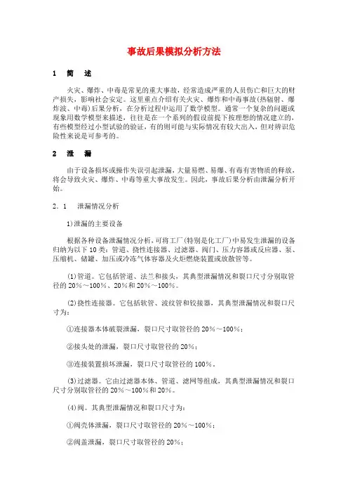
事故后果模拟分析方法1 简述火灾、爆炸、中毒是常见的重大事故,经常造成严重的人员伤亡和巨大的财产损失,影响社会安定。
这里重点介绍有关火灾、爆炸和中毒事故(热辐射、爆炸波、中毒)后果分析,在分析过程中运用了数学模型。
通常一个复杂的问题或现象用数学模型来描述,往往是在一个系列的假设前提下按理想的情况建立的,有些模型经过小型试验的验证,有的则可能与实际情况有较大出入,但对辨识危险性来说是可参考的。
2 泄漏由于设备损坏或操作失误引起泄漏,大量易燃、易爆、有毒有害物质的释放,将会导致火灾、爆炸、中毒等重大事故发生。
因此,事故后果分析由泄漏分析开始。
2.1 泄漏情况分析1)泄漏的主要设备根据各种设备泄漏情况分析,可将工厂(特别是化工厂)中易发生泄漏的设备归纳为以下10类:管道、挠性连接器、过滤器、阀门、压力容器或反应器、泵、压缩机、储罐、加压或冷冻气体容器及火炬燃烧装置或放散管等。
(1)管道。
它包括管道、法兰和接头,其典型泄漏情况和裂口尺寸分别取管径的20%~100%、20%和20%~100%。
(2)挠性连接器。
它包括软管、波纹管和铰接器,其典型泄漏情况和裂口尺寸为:①连接器本体破裂泄漏,裂口尺寸取管径的20%~100%;②接头处的泄漏,裂口尺寸取管径的20%;③连接装置损坏泄漏,裂口尺寸取管径的100%。
(3)过滤器。
它由过滤器本体、管道、滤网等组成,其典型泄漏情况和裂口尺寸分别取管径的20%~100%和20%。
(4)阀。
其典型泄漏情况和裂口尺寸为:①阀壳体泄漏,裂口尺寸取管径的20%~100%;②阀盖泄漏,裂口尺寸取管径的20%;③阀杆损坏泄漏,裂口尺寸取管径的20%。
(10)火炬燃烧器或放散管。
它们包括燃烧装置、放散管、多通接头、气体洗涤器和分离罐等,泄漏主要发生在简体和多通接头部位。
裂口尺寸取管径的20%~100%。
2)造成泄漏的原因从人-机系统来考虑造成各种泄漏事故的原因主要有4类。
(1)设计失误。
气动爆炸模拟器的制作方法1.引言1.1 概述概述部分内容:气动爆炸模拟器是一种用于模拟气体爆炸过程的实验装置,旨在通过模拟真实的爆炸环境,研究和探究爆炸现象的发生原理和特性。
通过此类实验装置,我们能够更好地理解爆炸过程的形成和演变规律,从而提高爆炸安全管理和防范措施的科学性与有效性。
在过去的几十年里,随着化工、矿产资源、能源等领域的快速发展,爆炸事故频发,给人们的生命财产安全带来了巨大的威胁。
为了有效防范和控制爆炸事故的发生,人们亟需开展相关研究工作,深入了解爆炸事故的发生机理和特性。
气动爆炸模拟器作为一种重要的实验手段,能够提供可控的实验环境,使我们能够模拟和研究真实的爆炸过程。
其制作方法主要包括确定实验目标和需求、选择适当的材料和工艺、设计并搭建实验装置等步骤。
通过灵活运用各种实验仪器和技术手段,我们可以模拟真实的爆炸环境,准确地测量和分析爆炸参数,探索和验证爆炸模型和理论。
本文将重点介绍气动爆炸模拟器的制作方法,旨在帮助读者了解和掌握气动爆炸模拟器的基本原理和工作原理,通过实验模拟和研究,提高爆炸事故的预测和防范能力。
通过对该实验装置的制作方法进行详细介绍,读者将能够了解到制作气动爆炸模拟器所需的材料和工艺,以及在制作过程中的注意事项和技巧。
通过本文的阅读,读者将获得一份关于气动爆炸模拟器制作方法的综合指南,具备一定的理论基础和技术能力,从而能够在实践中灵活运用气动爆炸模拟器进行研究和实验,为爆炸事故的防范和控制提供科学依据和技术支持。
1.2 文章结构文章结构部分的内容如下所示:文章结构:本文将按照以下的结构逐一介绍气动爆炸模拟器的制作方法。
首先,我们会在引言部分对本文进行概述,明确文章的目的和重要性。
接下来,在正文部分的第2.1节,我们将详细介绍相关的理论基础,包括气动爆炸的原理和相关的数学模型。
然后,在第2.2节中,我们会列举并详细讲解所需的制作材料,包括实验器材和工具等。
在结论部分的第3.1节,我们将总结实验结果,对实验中的关键数据进行分析和解读。

制作模拟爆炸效果的Blender教程Blender是一款功能强大的开源三维建模软件,它不仅可以用于建模和渲染静态图像,还可以创建各种动态效果,如模拟爆炸。
在本教程中,我们将学习如何使用Blender的粒子系统和物理模拟工具来制作逼真的爆炸效果。
步骤1:创建场景和基础对象首先,打开Blender并创建一个新的场景。
然后删除默认生成的立方体,并添加一个简单的球体作为我们的爆炸物体。
选择球体并将其缩放到适当的大小,以便它看起来像是一个容器,里面充满了爆炸物。
步骤2:设置粒子系统选中爆炸物体,进入“物理属性”选项卡,并点击“粒子”按钮以创建一个粒子系统。
在粒子系统设置面板中,将粒子类型设置为“重力”并调整重力参数,以便粒子向上运动。
接下来,将粒子生命周期设置得较长,这样它们就有足够的时间来形成一个爆炸的云团。
步骤3:调整粒子外观在外观选项卡中,可以调整粒子的外观。
可以选择使用自定义的粒子对象,例如球体或物体集合,而不仅仅是默认的点。
这将使粒子更加逼真,并使爆炸效果更加真实。
步骤4:设置物理模拟为了使爆炸效果看起来更真实,需要为粒子系统添加物理模拟。
在物理选项卡中,启用“刚体物理”和“碰撞”,然后调整相关参数,以便粒子会互相碰撞,并且在爆炸过程中保持能量和形状的一致。
步骤5:调整渲染设置在渲染选项卡中,可以调整粒子的渲染设置。
例如,可以选择使用点渲染或圆盘渲染来代替默认的线渲染,以便更好地展现粒子的形状。
还可以调整物体大小和颜色,使其更逼真。
步骤6:模拟爆炸效果现在,我们已经设置好了爆炸的基本参数,可以开始模拟爆炸效果了。
在3D视图中,点击“模拟”选项卡并选择“动力学”面板,然后点击“模拟”按钮。
Blender将开始计算并显示粒子的运动过程。
步骤7:渲染和调整当模拟完成后,可以使用Blender的渲染引擎进行最终渲染。
在渲染输出选项卡中,可以调整渲染分辨率和帧率。
点击“渲染”按钮,Blender将生成逼真的爆炸效果,并输出为动画序列或视频文件。

固体击发爆炸的原理和模拟方法固体击发爆炸是一种常见的爆炸形式,它通常是由于外力作用导致固体内部的能量超过了临界值而引起的。
在实际应用中,我们需要对这种爆炸进行精确的模拟和预测,以确保安全性和可靠性。
本文将介绍固体击发爆炸的原理和模拟方法,并探讨其在实际应用中的重要性。
一、固体击发爆炸的原理固体击发爆炸是一种由外力作用引起的爆炸,它是一种机械能转化为化学能的过程。
通常,固体内部的化学键会在受到外力作用下断裂,释放出大量的化学能,从而引起爆炸。
这种爆炸通常伴随着火焰、热量和压力波的产生,具有强烈的破坏性和危险性。
固体击发爆炸的能量来源是外力作用,其临界值取决于固体的物理和化学性质。
一般来说,当受到的外力超过了一定的阈值时,固体内部的化学键就会断裂,从而引起爆炸。
此时,爆炸所产生的能量将会以各种形式释放出来,如火焰、热量和压力波等。
二、固体击发爆炸的模拟方法为确保工业和军事应用中的固体击发爆炸的安全性和可靠性,我们需要对这种爆炸进行精确的模拟和预测。
一般来说,固体击发爆炸的模拟可以采用数值模拟方法,即通过计算机模拟来预测和分析爆炸的过程和结果。
固体击发爆炸的数值模拟通常可以采用爆炸动力学方法。
这种方法将爆炸过程看作是一种复杂的动力学系统,并将其建模为一组基于物理和化学原理的微分方程组。
然后,通过求解这组微分方程组,我们可以预测和分析爆炸的各种参数,如火焰、热量、压力波等。
在进行数值模拟之前,我们需要确定固体击发爆炸的所需参数,如固体的物理和化学性质、外力的大小和方向等。
这些参数的准确性和精度对模拟结果的准确性和可靠性至关重要。
三、固体击发爆炸的应用固体击发爆炸在多个领域得到了广泛应用,如工业制造、民用和军事,其中最重要的应用包括火箭发动机、炸药、汽车和飞机等。
火箭发动机是固体击发爆炸在航空航天领域中的最重要应用之一。
它通常采用固体发动机,其中液体燃料被固体催化剂燃烧,释放出巨大的能量,从而推动火箭飞行。

受限空间可燃气体爆炸数值模拟共3篇受限空间可燃气体爆炸数值模拟1受限空间可燃气体爆炸数值模拟随着现代工业的发展,使用可燃气体的设备和工具越来越广泛,而受限空间内的气体爆炸则可能带来严重的危害。
为了深入研究受限空间可燃气体爆炸的规律,许多科学家和工程师开展了大量的研究工作。
在这些研究中,数值模拟已经被证明是一种有效的方法。
本文将深入探讨受限空间可燃气体爆炸的数值模拟方法和相关研究成果。
受限空间可燃气体爆炸是指在密闭或部分密闭空间内,由于气体中可燃物质的浓度超过了爆炸下限,当热源或点火源出现时,空间内的气体发生爆炸而引发事故。
这样的事故可能会造成严重的人员伤亡和财产损失。
因此,对于受限空间可燃气体爆炸的研究已经引起了广泛的关注。
数值模拟是一种重要的研究方法,它能够模拟真实环境中的各种物理现象,如流体力学、热传导等。
在受限空间可燃气体爆炸的研究中,数值模拟也被广泛应用。
数值模拟可以帮助研究人员深入了解气体爆炸在缩放模型中的行为,研究爆炸的发生机理和影响因素,并预测事故的可能性和危害程度。
现在,常用的数值模拟方法主要有两种,即欧拉模拟和拉格朗日模拟。
欧拉模拟是一种基于物理模型的数值模拟方法,它主要通过求解基本方程组,如动量方程、能量方程和质量守恒方程,来分析流动问题和热传导等现象。
欧拉模拟可以考虑气体的压缩性和温度变化等因素,有较高的精度和可靠性。
但是,在处理流动中的非线性问题时,欧拉模拟可能会出现数值耗散或不稳定等问题。
相比之下,拉格朗日模拟则是一种优秀的数值模拟方法。
该方法基于粒子的运动状态,可以准确地模拟流体的运动。
在受限空间可燃气体爆炸的研究中,拉格朗日模拟经常被应用于爆炸物体以及火焰传播过程的研究。
通过对流体中每个粒子的运动状态进行跟踪并计算,可以非常准确地模拟出爆炸和火焰传播的过程。
虽然欧拉模拟和拉格朗日模拟各有优劣,可以根据具体问题选用不同的数值模拟方法。
但无论采用何种方法,都需要满足数值模拟的准确性和可靠性的要求。
一、实验目的1. 了解乙炔的爆炸特性及其爆炸极限。
2. 掌握模拟乙炔爆炸实验的操作步骤和安全注意事项。
3. 培养实验操作技能和安全意识。
二、实验原理乙炔(C2H2)是一种无色、无味、易燃的气体,其爆炸极限为2.5%~82%。
当乙炔与空气混合达到爆炸极限时,遇明火或高温即可发生爆炸。
本实验通过模拟乙炔爆炸,观察爆炸现象,了解乙炔的爆炸特性。
三、实验仪器与试剂1. 仪器:乙炔发生器、酒精灯、量筒、试管、集气瓶、铁夹、铁架台、导气管、酒精喷灯、玻璃棒等。
2. 试剂:乙炔气体、空气。
四、实验步骤1. 准备实验器材:将乙炔发生器、酒精灯、量筒、试管、集气瓶、铁夹、铁架台、导气管、酒精喷灯、玻璃棒等实验器材准备好。
2. 制备乙炔气体:将乙炔发生器放在通风良好的实验室内,向其中加入适量的水,并加入一定量的电石(CaC2)。
3. 连接实验装置:将导气管插入乙炔发生器,另一端连接到集气瓶,集气瓶置于铁架台上。
4. 点燃酒精灯:点燃酒精灯,对集气瓶进行预热。
5. 观察爆炸现象:待集气瓶内温度升高后,用酒精喷灯点燃导气管出口处的乙炔气体,观察爆炸现象。
6. 实验结束:待爆炸现象结束,关闭酒精喷灯,回收实验器材。
五、实验结果与分析1. 实验结果:在点燃导气管出口处的乙炔气体后,集气瓶内发生爆炸,产生巨大的响声和火光,集气瓶瞬间被炸裂。
2. 分析:本实验成功模拟了乙炔爆炸现象,说明乙炔气体具有强烈的爆炸性。
实验过程中,乙炔与空气混合达到爆炸极限,遇明火或高温引发爆炸。
六、实验讨论1. 乙炔爆炸的危险性:乙炔具有强烈的爆炸性,实验过程中必须严格遵守操作规程,确保实验安全。
2. 安全注意事项:实验过程中,应保持实验室内通风良好,避免乙炔气体泄漏;操作时,应佩戴防护眼镜、手套等个人防护用品;点燃乙炔气体时,应远离易燃易爆物品。
七、实验总结本次模拟乙炔爆炸实验,使我们对乙炔的爆炸特性有了更深入的了解。
通过实验,我们掌握了模拟乙炔爆炸实验的操作步骤和安全注意事项,提高了实验操作技能和安全意识。
dyna模拟爆炸原理爆炸现象是一种剧烈的物质变化过程,通常由于快速释放大量的能量所导致。
这种能量释放造成了巨大的冲击波、火焰、光辉和声音。
而Dyna(动力)模拟爆炸原理是一种以计算机仿真的方式来模拟和研究爆炸现象的方法。
Dyna是一种研究爆炸动力学的工具,它基于有限元法和蝉联多体动力学模型。
它可以模拟各种爆炸事件,包括化学爆炸、燃气爆炸、炸药爆炸以及一些特殊情况下的爆炸事件,如车辆碰撞和建筑物破坏等。
Dyna模拟爆炸原理的基本步骤如下:1.问题定义:确定要模拟的爆炸事件,包括爆炸物质的性质、模拟的尺度和模型的几何形状。
2.材料参数设定:根据实验数据或经验公式,确定模拟所需的材料参数,如密度、热容、断裂强度等。
3.网格划分:将要模拟的物体划分为有限元网格,网格的细化程度取决于模拟精度的要求。
4.物理模型设定:根据实际情况,设定模拟所需的物理模型,如爆炸物质的燃烧模型、材料的热膨胀模型等。
5.边界条件设定:根据实际情况,设定模拟所需的边界条件,如初始温度、初始应变等。
6.求解过程:使用数值求解算法,根据设定的物理模型和边界条件,求解时间和空间上的物理场。
7.结果分析:根据求解得到的物理场,分析爆炸事件中发生的各种现象,如冲击波的传播、物体的位移和破坏等。
通过Dyna模拟爆炸原理,可以获得一系列爆炸事件中的关键信息,例如爆炸物质在爆炸过程中的能量释放、物体的响应和破坏情况等。
这对于爆炸安全评估、爆炸事故调查以及爆炸物质设计和防护措施的制定都具有重要意义。
然而,Dyna模拟爆炸原理也存在一些限制。
首先,由于爆炸事件的复杂性,模拟结果的准确性受多个因素的影响,如材料参数的准确性、模型的精细度以及边界条件的准确性等。
其次,计算机模拟的结果只是一种近似,不能完全代替实验结果。
因此,在使用Dyna模拟爆炸原理时,需要慎重考虑和解释模拟结果,同时结合实验数据进行综合分析。
总之,Dyna模拟爆炸原理是一种研究爆炸动力学的有效工具,它通过计算机仿真的方式,可以模拟和研究各种爆炸事件。
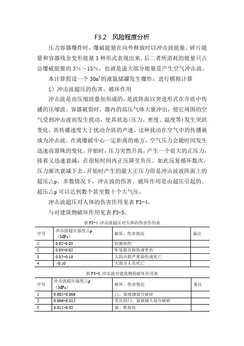
F3.2 风险程度分析压力容器爆炸时,爆破能量在向外释放时以冲击波能量、碎片能量和容器残余变形能量3种形式表现出来。
后二者所消耗的能量只占总爆破能量的3%~15%,也就是说大部分能量是产生空气冲击波。
本计算假设一个30m3的液氮储罐发生爆炸,进行模拟计算1)冲击波超压的伤害、破坏作用冲击波是由压缩波叠加形成的,是波阵面以突进形式在介质中传播的压缩波。
容器破裂时,器内的高压气体大量冲出,使它周围的空气受到冲击波而发生扰动,使其状态(压力、密度、温度等)发生突跃变化,其传播速度大于扰动介质的声速,这种扰动在空气中的传播就成为冲击波。
在离爆破中心一定距离的地方,空气压力会随时间发生迅速而悬殊的变化。
开始时,压力突然升高,产生一个很大的正压力,接着又迅速衰减,在很短时间内正压降至负压。
如此反复循环数次,压力渐次衰减下去。
开始时产生的最大正压力即是冲击波波阵面上的超压△p。
多数情况下,冲击波的伤害、破坏作用是由超压引起的。
超压△p可以达到数个甚至数十个大气压。
冲击波超压对人体的伤害作用见表F3-4。
与对建筑物破坏作用见表F3-5。
表F3-4 冲击波超压对人体的伤害作用表表F3-5 冲击波对建筑物的破坏作用表2)冲击波的超压 (1)模拟比与1000kgTNT 的爆炸模拟比α的求取公式:则可求得α=0.1308 (2)人员伤害基准目标距离1000kgTNT 炸药在空气中爆炸时所产生的冲击波超压表见表F3-6。
根据表F3-5中人员的伤亡、重伤、轻伤中冲击波超压的ΔP 值,再根据表F3-7中1000kgTNT 爆炸时的冲击波超压表,用插入法求得。
超压值相对应的距离为:爆炸冲击波致人死亡的半径距离R 死=23.5m ;爆炸冲击波致人内脏重伤损伤或死亡的半径距离R 重=32.5m ; 爆炸冲击波致人听觉器官损伤或骨折的半径距离R 骨折=40m ; 爆炸冲击波致人轻微损伤、墙体破裂的半径距离R 轻=58m 。
(3)人员的伤害距离 人员伤害距离 R=R0×α根据公式求取结果见表F3-7。
一、背景设定某市化工园区内,一家大型化工企业正在进行一种新型化工产品的生产。
由于操作失误,一名工人误触了含有易燃易爆化学品的设备,导致设备发生爆炸。
爆炸瞬间产生巨大火焰和冲击波,周边设施受到破坏,现场一片狼藉。
事故发生后,企业迅速启动应急预案,并立即向政府应急管理部门报告。
二、事故现场情况1. 火灾情况:爆炸导致现场起火,火势猛烈,蔓延迅速,可能对周边设施和人员造成威胁。
2. 人员伤亡:初步统计,事故已造成5名工人受伤,其中2人重伤,需要立即进行救治。
3. 设备损坏:爆炸造成生产线设备严重损坏,部分化学品泄漏,对环境造成污染。
4. 通讯中断:爆炸导致现场通讯设施损坏,与外界联系困难。
三、应急预案启动1. 企业内部应急响应:- 立即启动应急预案,组织现场人员进行紧急疏散。
- 成立现场指挥部,由企业主要负责人担任总指挥,下设现场救援组、医疗救护组、环境保护组、信息联络组等。
- 疏散周边无关人员,设置警戒线,防止无关人员进入危险区域。
- 启动消防设施,进行灭火救援。
- 携带医疗救护设备,对受伤人员进行救治。
2. 政府应急管理部门响应:- 收到企业报告后,立即启动市级应急预案,成立现场指挥部,由市应急管理部门主要负责人担任总指挥。
- 指挥部下设现场救援组、医疗救护组、环境保护组、信息联络组、后勤保障组等。
- 调集消防、公安、医疗、环保、交通等相关部门力量,协同作战。
- 对事故现场进行空中侦察,评估事故影响范围。
- 启动应急预案,开展救援行动。
四、救援行动1. 灭火救援:- 消防部门调集大量消防车辆和消防队员,对火灾进行扑救。
- 采用灭火器、泡沫灭火剂、干粉灭火剂等多种灭火手段,迅速控制火势。
- 针对爆炸引起的次生灾害,采取针对性措施进行处置。
2. 医疗救护:- 医疗救护组对受伤人员进行紧急救治,将重伤员送往附近医院。
- 对轻伤员进行现场救治,确保其生命安全。
3. 环境保护:- 环保部门对泄漏的化学品进行检测,评估污染情况。
模拟宇宙爆炸实验报告实验目的:本实验旨在模拟宇宙爆炸,深入了解宇宙中的大爆炸现象及相关的物理规律。
实验器材:1. 模型宇宙:- 一个大型容器,用于构建模型宇宙;- 空气压缩机,用于模拟宇宙膨胀;- 真空泵,用于模拟宇宙的真空环境;- 透明罩子,用于保护实验环境。
2. 实验观测与测量设备:- 高速摄影机,用于捕捉爆炸过程中的细微变化;- 热敏纸,用于记录爆炸过程中的温度变化;- 挂钟,用于记录爆炸过程的时间。
实验步骤:1. 准备工作:- 组装模型宇宙:将大型容器组装起来,并确保其稳定性; - 将空气压缩机和真空泵连接至模型宇宙;- 测试设备:确保高速摄影机、热敏纸和挂钟正常工作。
2. 模拟宇宙爆炸:- 施加初始能量:通过空气压缩机,向模型宇宙注入一定的气体,增加压力;- 启动真空泵:同时启动真空泵,将模型宇宙内的气体抽空至接近真空状态;- 监测变化:利用高速摄影机、热敏纸和挂钟,记录爆炸过程中的各项指标变化,如压力、温度、时间等。
3. 数据分析与结果:- 对高速摄影图像进行分析:观察爆炸过程中的物质分散、膨胀及扩散情况;- 热敏纸记录分析:根据热敏纸上的温度变化曲线,推测宇宙爆炸过程中的温度变化规律;- 时间记录分析:通过挂钟记录的时间数据,计算出爆炸过程中的时间间隔,进一步研究爆炸的快速性。
实验结果分析:根据实验中观测到的现象和数据分析,得出以下结论:1. 宇宙爆炸过程中,物质会迅速膨胀、分散,并扩散到较大范围;2. 温度在爆炸后短暂升高,然后逐渐降低,随着宇宙的扩张,温度进一步下降;3. 爆炸过程极快,持续时间较短,需要高精度测量工具才能准确记录。
实验结论:通过模拟实验,我们加深了对宇宙爆炸现象以及相关物理规律的理解。
宇宙爆炸是一个巨大的能量释放过程,产生了空间膨胀、物质分散和温度变化等现象。
该实验为深入研究宇宙爆炸提供了一种可行的方法,并为进一步开展相关研究提供了有益的参考。
爆炸现象的模拟与分析研究一、引言爆炸是一种极为危险和破坏性极强的现象,其对人类和环境的影响十分深远。
为了更好地研究和控制这种现象,需要深入了解爆炸的物理过程及其对周围环境的影响。
本文将依托国内外前沿科技和理论知识,对爆炸现象进行模拟与分析,探究其发展规律和控制方法,以期提供参考和借鉴。
二、爆炸现象的定义和分类爆炸是指物质在一定条件下发生突然而剧烈的化学或物理反应,释放出大量的热能、光能和声能,产生爆震波和高速气流,对周围环境造成一定的破坏和影响。
按照爆炸材料的形态和爆炸过程的特点,爆炸现象可以分为以下几类:1.气体爆炸:指气体在一定条件下发生燃烧反应,释放出大量的热能和光能,产生火焰和爆炸波。
2.液体爆炸:指液体在一定条件下发生燃烧反应或化学反应,瞬间蒸发产生气体,从而形成爆炸。
3.固体爆炸:指固体材料在一定条件下发生物理或化学反应,释放出大量的热能和气体,形成火焰和爆炸波。
三、爆炸现象的模拟方法为了更好地探究爆炸现象的物理规律和机理,需要采用不同的模拟方法进行研究,常用的方法如下:1.数值模拟法:利用计算机模拟爆炸过程中热力学、动力学等物理过程,通过迭代计算得到爆炸波、温度、压力等参数变化规律。
2.实验模拟法:在实验室内进行爆炸实验,观察和记录爆炸现象的各种参数变化,分析爆炸机理和影响。
3.理论分析法:基于物理学和化学学的基础理论,对爆炸过程进行分析和推导,探究爆炸的规律和特点。
四、爆炸现象的模拟和分析实例以气体爆炸为例,本文将采用数值模拟法进行研究。
根据爆炸现象的特点,模拟计算中需关注以下参数:1.燃爆速度:指一定条件下反应物的燃烧速度,是气体爆炸时最重要的参数之一。
2.爆炸波压力:指爆炸产生的压力波在空气中传播和扩散的效应。
3.爆炸波速度:爆炸波在空气中传播的速度,是爆炸能量传递和扩散的重要参数。
基于以上参数,本文利用计算机自主编写程序,并以一个格子状的模型作为仿真对象,进行数值模拟实验。
空气中TNT爆炸冲击波超压峰值的预测及数值模拟摘要:通过对空气中TNT爆炸冲击波超压峰值的已有研究成果进行比较分析,发现不同学者对其预测结果存在一定差别,并据此拟合总结出能较好地描述冲击波超压峰值与比例距离关系的表达式。
同时用LS2DYNA动力有限元软件模拟了2种不同装药量条件下空气中TNT炸药爆炸产生的冲击波的传播,模拟所得的超压峰值小于经验公式的结果,装药量大的模拟结果更接近经验公式预测值。
有必要对爆炸冲击波的参数和经验公式进行进一步的研究。
关键词:冲击波;超压峰值;比例距离;数值模拟TNT在空气中爆炸时,形成了一团瞬间占据炸药原有空间的高温、高压气体。
这团气体猛烈地推动周围静止的空气,同时产生一系列的压缩波向四周传播,各个压缩波最终叠加成冲击波[1]。
自由空气中的理想冲击波波形即P-t曲线如图1所示[2]。
由图可见,冲击波在历时Ta到达后,该处压力经过时间Tr由大气压力Po 突跃至最大值。
压力最大值与Po的差值称为入射超压峰值Pso。
压力在时间Td 内经指数衰减到大气压力后再继续下降,直至出现负超压峰值,在一定时间内又逐渐地回升到大气压力。
目前,研究者主要用冲击波压力、超压峰值、冲量、持续时间等冲击波参数来描述TNT爆炸产生的入射冲击波的传播规律,而冲击波的各种参数常通过比例距离来表达。
比例距离可以定义为:Z=R/W1/3 (1)式中,R为测点与爆心之间的距离,m;W为等效TNT药量,kg。
1 冲击波超压峰值的研究通过试验研究和理论推导,不少学者对空气中TNT爆炸产生的入射冲击波的传播规律提出了自己的见解,特别是对冲击波峰值超压的研究方面总结出了不少的预测公式,下面简要叙述一下常见的几个经验公式。
Brode(1955)认为TNT爆炸冲击波峰值超压(单位:MPa)可用下式确定[2-3]:Henrych(1979)给出的空气中冲击波峰值超压(单位:MPa)的表达式为[4]:Mills(1987)介绍了TNT爆炸冲击波峰值超压(单位:MPa)的一种表达式[1]:Crawford和Karagozian(1995)推荐求解峰值超压(单位:psi)的表达式为[1]:式中,Po为大气压力,psi;R为地面测试点与爆源之间的距离,m。
爆炸模拟演练方案1. 引言在现代社会中,爆炸事件的发生时有发生,对人民的生命财产安全造成了严重威胁。
为了提高应急处置能力、保障公众的安全,进行爆炸模拟演练是一种非常重要的方法。
本文将详细介绍爆炸模拟演练的方案,包括准备工作、模拟演练过程和总结评估等内容。
2. 准备工作在进行爆炸模拟演练前,需要做好充分的准备工作,以确保演练的顺利进行。
具体准备工作如下:2.1 制定演练计划在演练前,需要制定详细的演练计划。
计划应包括演练的目标、演练的时间和地点、演练的阶段、参与演练的单位和人员等内容。
同时,还需要明确各个演练阶段的任务和时间节点,以确保演练的有序进行。
2.2 组建演练队伍为了保证演练的顺利进行,需要组建一个专业的演练队伍。
演练队伍应包括安全专家、救援人员、医疗人员等。
队伍成员需要经过专业培训,具备相应的应急处置能力。
演练需要使用一些特定的装备和设备。
根据演练的需要,确定所需装备,包括防护服、呼吸器、传感器等。
同时,需要确保装备完好,能够在演练中正常使用。
2.4 设置演练场地选择合适的演练场地是演练成功的关键。
演练场地应具备一定的空间,能够模拟真实的爆炸环境。
同时,需要确保演练场地的安全性,以防演练中出现意外事故。
3. 模拟演练过程模拟演练是一种模拟真实爆炸事件的方式,旨在提高处置人员的应急能力。
本节将详细介绍爆炸模拟演练的过程。
3.1 演练前准备在演练前,需要对演练场地进行清理和布置工作。
确保演练场地整洁有序,清除可能影响演练的障碍物。
同时,根据演练计划,设置和布置各种模拟装置,以模拟真实的爆炸环境。
3.2 演练过程在演练过程中,演练队伍按照预定的计划和时间节点进行应急处置。
演练阶段包括事故发生、应急响应、现场救援和伤员救治等。
演练队伍需要紧密配合,按照预定的应急程序和操作规范进行处置。
演练结束后,需要进行总结和评估。
通过总结评估,可以发现演练中存在的不足和问题,并进行改进。
同时,还可以从演练中获取宝贵的经验,提高应急处置能力。
对储存带压液态气体储罐发生爆炸事故后果模拟计算对储存带压液态气体储罐采用定量计算方法,预测压缩气体容器爆炸事故后果,并对计算后果进行分析。
该项目水线吹瓶压缩空气高压罐的压力容器基本数据: 体积:V=3m 3,绝对压力:P=4.2Mpa 根据安全评价有关爆炸事故模拟计算过程如下: (1)计算发生爆炸时释放的爆破能量:E g =C g ·V ;32857.0101013.015.2⨯⎥⎥⎦⎤⎢⎢⎣⎡⎪⎭⎫ ⎝⎛-==P PV V C E g g式中:E g —气体的爆破能,kJ ;C g ——压缩气体爆破能量系数,kJ/m 3;V ——容器的容积,m 3;p-容器内气体的绝对压力,MPa ; 由公式代入数据得:E g =20632 kJ(2)将爆破能量E g 换成TNT 当量q ,代入数据: q=E g /q TNT =E g /4500则:q=4.58 (3)爆炸的模拟比a ,即:a=(q/q 0)1/3=(q/1000)1/3=0.1q 1/3则: a=0.166(4)在1000kgTNT 爆炸试验中相当的距离R 0,则 R 0 = R/a 或R = R 0·a式中,R —目标与爆炸中心的距离,m ;R 0—目标与基准爆炸中心的相当距离,m 。
△p(R)=△p 0(R /α) 或△p(R 0·a)=△p 0(R 0)表5.7-1 1000kgTNT 爆炸时的冲击波超压(5)根据表5.7-1给出的相关数据,在距离爆炸中心不同半径处的超压,见表5.7-2。
表5.7-2 距离爆炸中心不同半径处的超压(6)离爆炸中心不同半径处冲击波超压对建筑物的破坏作用表5.7-3 冲击波超压对建筑物的破坏作用由表5.7-2和见表5.7-3可知,离爆炸中心不同半径处冲击波超压对建筑物的破坏作用见表5.7-4。
表5.7-4 不同半径处冲击波超压对建筑物的破坏作用(7)不同半径处冲击波超压对人体的伤害作用表5.7-5 冲击波超压对人体的伤害作用由表5.7-2和见表5.7-5可知,离爆炸中心不同半径处冲击波超压对人体的伤害作用见表5.7-6。
Simulation of Energy Absorbing Materialsin Blast Loaded StructuresMichael J. Mullin, mikemullin@Brendan J. O’Toole, bj@Department of Mechanical EngineeringUniversity Nevada Las VegasAbstractEnergy absorbing materials such as foam or honeycomb are of interest in blast protection because of their ability to absorb energy through plastic deformation. After reaching their yield stress, these materials exhibit a region of constant stress for increasing strain until the material is completely compacted. The energy needed to crush the material is proportional to the area under the stress-strain curve. Because foams and honeycombs have this “plateau” region, they absorb a considerable amount of energy relative to their low density. These materials are investigated to determine if their energy absorbing abilities can be used to mitigate the load and shock transferred to a vehicle structure subject to blast loading.Ballistic pendulum experiments show that energy absorbing materials increase the imparted impulse from a blast. This behavior was contrary to expected results so computational models were created in LS-DYNA to understand the phenomenon that causes an increase in imparted impulse. ConWep and Arbitrary-Lagrangian-Eulerian (ALE) techniques were used in simulations to demonstrate their efficiency and accuracy. An additional ConWep aluminum foam model was created to directly compare simulations against ballistic pendulum experiments found in the literature.1. IntroductionAs the military industry moves forward into the 21st century, strong lightweight materials are changing their status from exotic to commonplace. Vehicles are being reevaluated to create a safer, more efficient, and more lethal vehicle with significant weight savings. Survivability from mine blast is of particular concern: as weight is reduced, the accelerations of the vehicle when subjected to mine blast aluminum increases. A sacrificial layer of material that can absorb some or all of the blast energy is one possibility for light vehicle survivability. Metal foams and honeycombs are materials that absorb a considerable amount of energy relative to their low density.A simple device to measure impulse imparted to a structure from a blast is a ballistic pendulum (Figure 1). With a charge detonated in front of the pendulum, the face is subjected to a pressure wave, which causes the pendulum to rotate a measurable amount. Knowing the rotation of the center of mass (cm in Figure 1) and the distance from the rotation center, the imparted impulse from the blast can be calculated. Panels of various shapes and materials can be placed on the face of the pendulum to investigate their abilities to reduce the imparted impulse. With the material absorbing some of the energy, the resulting rotation of the structure was expected to be reduced. Ballistic pendulum experiments show opposite results; energy absorbing materials placed on the front of the panel caused an increase in rotation [1][2].Hanssen et al. [1] performed ballistic pendulum tests on Al foam panels as early as 1998. Hannsen showed an increase in imparted impulse to Al foam panels subjected to close range blast. This increase was attributed to collapse of the foam under the blast (dishing), which allowed confinement of the blast. Hanssen used numerical models to show that although anincrease in impulse was observed, the transmitted force through the Al foam panels was decreased.Figure 1: Ballistic Pendulum and Representative Models Diagram.This paper compares two loading methods available in LS-DYNA: one using a Lagrangian model and the ConWep air blast function and the other using Arbitrary Lagrangian-Eulerian (ALE) coupling including the explosive material as part of the model. Although these models use the same standoff, equivalent charge mass and material properties, they are not representative of any physical experiment. A separate ConWep model is presented that compares ConWep’s capabilities against experimental values for simulating blast loading of Al foam panels.2. Blast Loading Using LS-DYNABoth ConWep and ALE techniques have been validated for simulating mine blast [3],[4],[5]. Randers-Pehrson [3] describes the ConWep air blast function and concluded the function as adequate for use in mine blast applications. Similarly, Wang [4] benchmarked material properties used in ALE modeling of detonating landmines. Williams [5] compared ConWep to a commercially unavailable mine blast algorithm and concluded ConWep as apt if a scale factor is determined for the soils being used. The ballistic pendulum, which is what the models presented here simulate, is more appropriately simulated with an air blast. The effect of soil is not an issue, so standard practice values [3],[4],[5],[6] are used for the representative models.In order to reduce the computational expense of modeling the maximum displacement of a pendulum (with a period of over 2.5 seconds) with a time step appropriate for capturing ballistic phenomena, simpler models were devised (Figure 1). These simpler models consist of a sled of known mass subjected to the same blast load the pendulum counterpart would be exposed to. The sled has the same area exposed to the blast as the pendulum bob as well as the same mass. When the sled is subjected to the impulse of the blast, it will undergo acceleration until the sled reaches a maximum velocity (upon completion of the impulse). The resulting kinetic energy, which iscalculated using the maximum velocity of the sled, is comparable to the potential energy calculated from the maximum height of the pendulum swing.The following two subsections describe the models made to compare the different loading methods of ConWep and ALE. Both methods have a rigid body model and an Al foam model. For the foam models, the foam panel is attached to the front of a rigid body support using a contact card. The exposed surface of the foam model has the same standoff as the exposed surface of the rigid body model (Figure 1).2.1 Lagrangian Models with ConWep Blast FunctionLS-DYNA’s ConWep air blast function has inputs of TNT equivalent mass, type of blast (surface or air), location in space of detonation, and surface identification for which the pressure will be applied. From this information, ConWep calculates the appropriate pressure to be applied to the designated surface. This method is computationally less expensive than the ALE method at the cost of accuracy: ConWep is unable to account for confinement (focusing of the blast due to geometry) or shadowing (when an object is blocking a surface from direct loading)[3].Figure 2: Discretization of Lagrangian panels. Foam elements (numbering 86,400) are shown in yellow, rigid body elements (numbering 10,800) are displayed in green.The rigid body model has dimensions (in x, y, z) of (50cm, 5cm, 25cm), consists of 10,800 elements, and is positioned 26.14 cm away from the source of the blast. The foam model (Figure 2) adds a panel of foam elements of the same dimensions as the rigid body and splitting each solid element into 8 equally sized smaller elements. All the Lagrangian elements use a single integration point element formulation and have a 1:1:1 aspect ratio. Quarter symmetry was used to reduce the number of elements in the model; all nodes on the planes of symmetry were constrained to stay on the planes of symmetry. *Contact_tied_surface_to_surface_offset was used to tie the rigid body to the foam plate. The “offset” option is necessary when tying a deformable part to a rigid body. The rigid body was chosen as the master and the foam as the slave for the contact algorithm.One pound of C-4 was chosen for the blast load simulations to be similar to ballistic pendulum experiments performed by Skaggs [2]. The ConWep air blast function requires an input for equivalent mass of TNT. C-4 explosives release more energy per pound than TNT by afactor of 1.14 [5], [6]. Using that factor and converting from lb to gm, the equivalent mass of the TNT used in these studies is 517.1gm.2.1.1 Material PropertiesMaterial properties for the ConWep and ALE models are listed in Table 1. Some of the material properties required in these material cards are not easily described, so the values are displayed according to what is required for the LS-DYNA material cards. Wang [4] used a similar table structure and it is felt that this format displays the data in a format most useful to the end user.Table 1: Material Properties Used For ConWep And ALE Models.*MAT_RIGID (material 20) was used for the rigid body model. Material properties for steel were used with the exception of density. For all models, the overall mass of the sled was 4 kg; with a volume of 25000cm3 the density of the rigid body in the rigid body model was set to 0.16 gm/cc. The foam model has a rigid body support panel and a foam panel each with a volume of 25000 cm3. With the Al foam density at 0.15gm/cc, the rigid body’s density was set at 0.01gm/cc to keep the overall mass of the sled the same.*MAT_HONEYCOMB (material 26) was chosen for the Al foam material model. Material 26 offers uncoupled orthotropic behavior as seen in foams. Nonlinear elastoplastic material behavior can be defined separately (for each direction) for all normal and shear stresses. These curves can be used to define elastic-perfectly-plastic-rigid material behavior as seen in the majority of papers modeling foams subjected to high strain rates [1], [7],[8]. The values used for the foam material model were gathered from a couple of sources [1],[8].2.2 ALE ModelsUsing ALE in LS-DYNA involves modeling the charge and surrounding fluid with an Eulerian mesh, which is then coupled with a Lagrangian mesh (used for the foam and rigid bodypanel). Equations of State (EOS) are used for the High Explosives (HE) and air. The ALE method models the explosion and calculates the pressure profile throughout the Eulerian mesh. ALE is computationally more expensive than ConWep, and is only appropriate for small standoff distances: with the small Eulerian mesh needed to appropriately capture the pressure wave front, large amounts of elements are needed.Figure 3: Discretization of the ALE Eulerian mesh. There are 88,200 air elements and 304 HE elements in the original mesh; 128,284 and 4,000 elements in the refined mesh respectively.Several ALE models were constructed to improve the accuracy and efficiency of the models. The list includes an eighth symmetry rigid body model, a fourth symmetry rigid body model, a rigid body model with a refined Eulerian mesh, a rigid body model with an increased number of quadrature points, a foam model, and a foam model with a refined Eulerian mesh. The same amounts of Lagrangian elements (10,800 rigid and 86,400 foam) were used in the ALE models as were the ConWep models. In the eighth symmetry rigid body model (Figure 3), the number of Eulerian elements used to model the HE and air were 304 and 88,200 respectively. The mesh seen in (Figure 3) labeled “Original” was created by Powers [9] in a previous ALE parametric study. In the figure the red mesh shows the discretization of the air Eulerian elements, the blue mesh shows the High Explosive (HE) discretization. The darker area (highlighted) shows the Lagrangian part overlapping the Eulerian mesh, which explains why the mesh looks different in that region. The overall dimensions used in the x, y, and z directions are 55 cm, 40 cm, and 30 cm respectively. A 1:1:1 ratio was not achievable with the Eulerian mesh because of the spherical nature of the charge, but all elements are hexahedral. Boundary conditions disallowing motion normal to the planes were placed on the XY, XZ, and YZ planes (the three planes intersect at the center of the spherical explosive).A quarter symmetry model was constructed to address a boundary condition concern inherent with the eighth symmetry model: the constraints on the XZ plane of the eighth symmetry (Figure 3) model simulate another plate mirrored across the XZ plane. It was necessary to model quarter symmetry conditions to see if the affect, if any, the reflected blast wave from the mirrored plate had on the solution. A total of 18,598 (304 HE, 18,294 air) elements were mirrored about the XZplane allowing for quarter symmetry conditions while keeping the number of elements down (Figure 4). This addition of elements allowed the blast wave to reflect off of itself about the XZ plane while not calculating a full model (nor simulating another plate on the other side). Nodes along the YZ and the XY planes were constrained to stay on their respective planes. The darker region in Figure 4 (highlighted) is where the rigid body and air mesh overlap.AirExplosiveFigure 4: Quarter symmetry model: 106,190 Air (red) elements, 608 HE (blue) elements, 10,800 Rigidbody (within air mesh) elements.As reported by Wang [4], the mesh density significantly influences the peak pressure in theEulerian mesh. A new mesh was constructed (Figure 3) with 43,780 more Eulerian elements, to understand mesh effects for this set of models. Maximum velocity of the sled with the refined mesh was within 8% of the original mesh.2.2.1 Material PropertiesThe rigid body and Al foam material properties are the same as those found in the ConWepsection and are listed in Table 1. Air and HE material properties and equation of state (EOS) parameters were obtained from [4] and are also listed in Table 1.2.2.2 Arbitrary-Lagrangian-Eulerian CouplingFor accurate solutions, two Eulerian elements must fit across one Lagrangian element whencoupling the two meshes [9]. This sizing promotes appropriate advection from Eulerian to Lagrangian elements. Increasing the number of quadrature points, which are used to couple the Lagrangian and Eulerian elements, can be used in place of mesh refinement for fluid-structure contact issues. If the number of quadrature points is not enough, the solution will underpredict the energy transferred from the blast. Increasing the number of quadrature points significantly increases the computational expense. Considering the mesh densities used in these models, four quadrature points are used for the rigid body model and two are used for the Al foam model.To couple the foam and the rigid body support panels to the fluid, a part set containing bothpanels was used as the slave id on the in the *CONSTRAINED_LAGRANGE_IN_SOLID (*CLS) card. Using a part set allowed both parts to be coupled with the Eulerian fluid. One concern using this method is the number of quadrature points needed: the meshes of the rigid body and foam are different so a careful number is needed to keep costs down while not allowing penetration of the coarser mesh. It was decided to keep the number of quadrature points based on the foam mesh reasoning that the rigid body’s interaction with the fluid was not as significant:the rigid body is only exposed to the overpressure of the blast after it travels around the foam panel.Also on the *CLS card, the penalty factor was set to 0.2 and the coupling type (CTYPE) chosen allows for erosion of the Lagrangian elements. Examining the model after the part set was implemented showed all parts coupling appropriately without penetration. The time scale factor had to be reduced significantly for the ALE models: a value of 0.10 was needed for the foam models to run to completion.3. Results: ConWep vs. ALE3.1 Maximum Velocity/Kinetic EnergyMore ALE models were created than ConWep models because there are a lot more variables to consider using ALE. The sled velocity curves for all six ALE models are shown in Figure 5a, while tabulated results are located in Table 2. The kinetic energy was within 1% for the ALE eighth symmetry rigid body model, fourth symmetry rigid body model, and the rigid body model with 5 quadrature points. The refined Eulerian mesh model showed an increase of 7% in sled kinetic energy over the original mesh in the rigid body models and a decrease of 3% in the foam models.Figure 5: A) All ALE Models Sled Velocity vs. Time B) ConWep and ALE Sled Velocity Curves.As shown in Figure 5b and Table 2, using benchmarked parameters found in the literature [3], ConWep increases the KE of the sleds over ALE: 58% higher in the rigid body models, and over 115% higher in the foam model. The ConWep models show an increase in energy transferred to the foam models by 37% over the rigid body models; this behavior is seen in the experiments [1],[2]. ALE foam models show a slight decrease in energy transferred to the rigid body sled velocity, contrary to what has been shown in experiments.Table 2: ConWep and ALE Results.3.2 Computation TimeThe length of time to run the ALE models is significant: especially when coupled with a deformable material or when the number of quadrature points or elements is increased. The ALE rigid body eighth symmetry model took over 840x as much time as its ConWep counterpart. The ALE Foam model took as much as 38x as much time as the ConWep foam model, depending on the level of Eulerian mesh refinement.3.3 Foam BehaviorFigure 6 shows the Y-displacement contours of the 3 foam models at an elapsed time of 4.5E-4 seconds (when the foam is done deforming). Hanssen [1] showed similar foam panel deformation as seen in the ConWep model. The panels tested by Skaggs [2], which had a much larger cube root scaling [11], were completely destroyed by the explosive. The behavior seen in the ALE foam panels is unlike any physical experiments, and is dependent on the discretization of the Eulerian mesh.Figure 6: Y-Displacement Contours Of The Foam Panels At Maximum Deformation.4. Comparing Models to Experiments4.1 Modeling the Norwegian Ballistic Pendulum ExperimentIt was desirable to compare the numerical simulations with a ballistic pendulum experiment. Hanssen’s work [1] provided most of the details needed from his experiments to build a representative finite element model. Additional aluminum foam material properties not listed in Hannsen’s work were supplemented from [8]. With ConWep as the blast loading method of choice, sleds were constructed in the same manner as described in section 2.1. The dimensions of the foam panel match those of Hanssen’s. The rigid body support plate (red elements in Figure 7) is representative of the bare pendulum: the face area matches Hanssen’s and the dimension in the y direction was chosen so that the density of the rigid body could be set to a value in the range of steel. Quarter symmetry conditions were utilized to reduce the size of the model.Table 3: Material Properties Used To Match Experiments Performed By Hanssen [6].Figure 7: Discretization of Norwegian Foam Model NF-21160 Used To Compare Against Experiments.Foam elements (numbering 21,160) are shown in blue, rigid body elements (numbering 8,464) aredisplayed in red.4.2 Comparison With ExperimentThe rigid body model was originally run with no scale factor on the *LOAD_SEGMENT card. The model showed a 19% higher kinetic energy (KE) than the experiment, so the load curve was scaled down by a factor of 0.914 to match the experimentally measured KE. This factor was also used in the foam model. With the scaling factor, the rigid body model KE matches, but the foam model value is lower from the experimental foam model by about 25%.The mesh of the foam model was refined until the maximum velocity was within 3% of the last refinement. The velocity curves of the Norwegian Rigid Body model (NRB) and Norwegian Foam Models (NF-#) can be seen in Figure 8. Here the number after “NF” is the number of foam elements used in the model. All elements in foam models NF-21160 and NF-169280 have 1:1:1 aspect ratios. Foam elements in NF-169280 were split in the y-direction to build model NF-338560 (2:1:2 aspect ratio).Figure 8: Velocity Curves For Experiment Comparison Models.Table 4: Experiment And Model Results.Hanssen [1] reported a double curvature deformation pattern in the Al foam panels from the ballistic pendulum tests. Although the model predicts a higher amount of dishing than the experiments, the deformation pattern matches the double curvature behavior seen in the experiments (Figure 9). This pattern was not seen in the ALE results of the previous section.Figure 9: Y-Displacement Contours Of The Norwegian Ballistic Pendulum Model Under Maximum Deformation (Image Was Reflected About The Planes Of Symmetry).5. DiscussionAlthough the maximum sled velocity is close between the original and refined Eulerian mesh models, the patterns in the foam deformation vary. Additionally, the foam in the ALE models deformed much differently from the ConWep models. The ALE deformation patterns imply that the results are highly dependent on the Eulerian mesh. A spherical Eulerian mesh may improve the deformation of the foam, because it will allow the pressure wave to propagate outward normal to the solid element faces in all directions. The foam mesh refinement on the Norwegian foam model was not performed on the models used in ConWep/ALE comparison section. Further refinement of these models may bring out more discrepancies between the blast loading methods.The coupling between the Lagrangian and Eulerian meshes is problem specific. The LS-DYNA guidelines suggest two Eulerian elements to one Lagrangian element, which proved effective in these models. If that ratio is not possible, the number of quadrature points can be adjusted to improve the contact. The propagation of the pressure wave is more mesh dependent than the coupling between the Lagrangian and Eulerian elements.The ConWep air blast function is a lot simpler than the ALE models, and produces results seen in physical experiments. Hanssen [1] attributed the increase in impulse transferred to the Al foam ballistic pendulum tests as a factor of the foam deformation. He theorized that the dishing seen in the foam panels caused a focusing or confinement of the blast. Originally it was felt that this would not be demonstrated with ConWep models because ConWep does not account for confinement. In the ConWep algorithm [3], LS-DYNA looks up tables of information to determine pressure for a given cube root scaling value (not time). The algorithm implements Friedlander’s equation to find the rate of decay for the pressure. Friedlander’s equation uses the current model time, time to arrival, and duration time along with a decay coefficient to calculate the drop in pressure over time. A possible explanation for the increase in KE seen in the ConWepfoam models without accounting for confinement is that as the elements collapse, the orientation of the elements changes such that the angle of incidence is decreased (the faces become more normal to the blast). As the angle of incidence decreases, the reflected pressure on the element increases, resulting in an overall increase in impulse.The foam in the Norwegian models show more dishing then the results from the experiments. This increase in dishing may be transferring more of the blast energy to internal energy (IE) instead of kinetic energy (KE). The loss of KE to IE helps explain the difference between model and experiment. The experiment cannot produce a value for how much energy was converted to internal energy from foam deformation. Additionally, the foam material properties were gathered from a couple of sources because a complete set of values was not provided by Hanssen. Hourglass control had to be implemented in NF-338560, which helps explain why NF-338560 dished more than NF-169280.The conversion factor used to convert PE4 (used in the Norwegian ballistic pendulum experiments) to TNT was 1.043. Barker [12] explains in his results that the conversion of PE4 to a TNT equivalent is slightly on the conservative side. Barker’s statement compliments the 0.914 scaling factor on the ConWep load curve needed to equate the KE of the Norwegian rigid body model to the experiment.Kinetic energy was used to compare the results between models and experiments, but it is not the best factor for determining the Al foam’s effectiveness of mitigating blast damage. Although the Norwegian foam models reached a higher maximum velocity than the rigid body models, the slope of the velocity curves (acceleration) of the sleds was reduced. This could be crucial to vehicle occupants whom are limited to certain amounts of acceleration for survivability. Additionally, the foam undergoes constant stress from yielding until the densification strain is reached. With the level of stress limited to the collapse strength of the foam until densification, if the foam panel is thick enough not to completely densify through the thickness, the structure behind it (at a higher yield strength) could be saved.6. ConclusionThis paper compared two loading methods available in LS-DYNA: one using a Lagrangian model and the ConWep air blast function and the other using Arbitrary Lagrangian-Eulerian (ALE) coupling including the explosive material as part of the model. Additionally, a separate model using the ConWep air blast function compared simulation against ballistic pendulum experiments. Results showed ALE models as mesh dependent when coupled with deformable materials. ConWep models showed similar deformation patterns compared to experiments. With a scaling factor used to match the kinetic energy of the baseline models, the kinetic energy of the Norwegian foam model underpredicted and the dishing overpredicted the experiments. These discrepancies were related to more blast energy being converted to internal energy in the models than the experiments. From these results using common practice material properties, it is apparent that scaling factors will have to be determined for each experiment.AcknowledgementsThe authors would like to extend their gratitude to the DoD EPSCoR Program for supporting this work through the Army Research Office, Grant No. DAAD19-02-1-0105, “Development of Computational Tools for the Design and Optimization of Light Weight Armor”.References[1]Hanssen, A.G., L. Enstock, M. Langseth. “Close-range blast loading of aluminium foam panels.” InternationalJournal of Impact Engineering 27 (2002): 593-618.[2]Skaggs, R. Internal report on ballistic pendulum experimental results. Army Research Lab, 2003.[3]Randers-Pehrson, Bannister “Airblast Loading Model for DYNA2D and DYNA 3D” ARL-TR-1310 (1997).[4]Wang, J. “Simulation Of Landmine Explosion Using LS-DYNA3D Software: Benchmark Work Of SimulationOf Explosion In Soil And Air.” (DSTO-TR-1168). Fishermans Bend, Victoria, Australia: DSTO Aeronautical and Maritime Research Laboratory. 2001.[5]Williams, K., et al. “Validation of a Loading Model for Simulating Blast Mine Effects on Armoured Vehicles,”Proceedings from the 7th International LS-DYNA Users Conference, May 19-21 2002, Dearborn, MI: p 6-35 – 6-44.[6]Kinney, G. and K. Graham. Explosive Shocks in Air. 2nd Edition. Springer-Verlag New York Inc. New York,1985.[7]Hanssen, A.G., et al. “Validation Of Constitutive Models Applicable To Aluminium Foams”. InternationalJournal of Mechanical Sciences 44 (2002): 359-406.[8]Lopatnikov, S., et al. “Dynamics of metal foam deformation during Taylor cylinder-Hopkinson bar impactexperiment.” Composite Structures 61 (2003): 61-71.[9]Powers, B. “ws_flat.k” LS-DYNA input deck. Last Modified May 8, 2003.[10]Hallquist, J. O. LS-DYNA Theoretical Manual. Livermore Software Technology Corporation. May 1998.[11]Conventional Weapons Effects Program (ConWep), Technical Manual TM5-855-1, Fundamentals of ProtectiveDesign for Conventional Weapons, US Dept. of the Army, Washington, DC, 3 November, 1986.[12]Barker, G., D. Sharp. “Measurement of Blast Pressures.” .au/research/blast/blast.pdf :ADFAStudies. Produced by Australian Defense Force Academy. Viewed January 2004.[13]Deshpande, V.S., N.A. Fleck. “High strain rate compressive behaviour of aluminium alloy foams.” InternationalJournal of Impact Engineering 24 (2000): 277-298.[14]Gibson, L. J., M. Ashby. Cellular Solids: Structure & Properties. Oxford: Pergamon Press, 1988.[15]Hanssen, A.G., M. Langseth, O.S. Hopperstad. “Optimum Design For Energy Absorbtion Of SquareAluminium Columns With Aluminium Foam Filler”. International Journal of Mechanical Sciences 43 (2001): 153-176.[16]Hutchinson, John. “On the Design of Blast Resistant Sandwich Plates: The Talbot Lecture.” The TAM(Theoretical and Applied Mechanics) 400 Graduate Seminars. University Illinois Urbana Champaign. 1 May.2003.[17]LS-DYNA Keyword User’s Manual, Version 970. Livermore Software Technology Corporation. March 2003.。
基于Mie-Grüneisen状态方程的水下爆炸数值模拟Mie-Grüneisen方程是一种用于描述物质热物理性质的状态方程,它基于固体中声速的变化与压力、体积的关系。
在水下爆炸中,需要考虑爆炸产生的传播波,以及爆炸区域的物理和化学反应。
本文利用Mie-Grüneisen状态方程,对水下爆炸的数值模拟进行了研究。
首先,我们需要定义水下爆炸的物理模型。
假设一个爆炸在水中造成由水流动引起的压力波。
通过模拟流体动力学,我们可以得到压力波随时间的演变。
我们使用Navier-Stokes方程来预测水流的速度和压力。
这些方程可以写成以下形式:$\rho\frac{D\textbf{v}}{Dt} = \nabla \cdot \textbf{T} +\rho\textbf{f}$$\frac{Dp}{Dt} = -c_s^2\nabla\cdot\textbf{v}$其中,$\textbf{v}$是流体的速度,$\rho$是水的密度,$\textbf{T}$是应力张量,$\textbf{f}$是质量力,$p$是压强,而$c_s$是声速。
为了模拟炸药的化学反应,我们还需要添加一个爆炸源项。
我们将爆炸源视为一种化学能量积累的体积,然后在爆炸期间将化学能量转换为体积源项。
这些体积源项由以下方程给出:$S = \frac{cE_I}{V\Delta t}$其中,$E_I$是炸药的初始内能,$V$是物质的体积,$\Deltat$是模拟的时间步长,而$c$是炸药的燃烧速率。
最后,我们需要考虑爆炸造成的物质变形和热膨胀问题。
我们使用Mie-Grüneisen方程来模拟这些现象,该方程描述了固体中声速与压力和密度的关系:$c_s^2 = \frac{K + \frac{4}{3}\mu}{\rho} +\frac{3\gamma}{2}aT$其中,$K$和$\mu$是Lame常数,$\gamma$是Grüneisen常数,$a$是体积膨胀系数,$T$是物体的温度。
1、爆炸模拟的一般过程
(1)首先要有一个总体思路,怎样把爆炸程转化为程序模型(明白该怎样建立自己的模型,选取材料模型,采用哪儿种算法计算求解),这一步很重要,直接关系计算结果的合理性。
(2)前处理,包括:画图、建模、划分网格、定义边界及约束条件、设定分析控制选项、输出K文件等。
(3)有些前处理不支持LS-DYNA的K文件中关键字,需修改完善K文件(注:K文件的中关键字格式十分重要,需要注意)。
(4)计算求解。
如果有错误终止计算,根据错误提示,查找并修改出错的地方,使计算正常结束。
(5)后处理。
结果分析,提取自己关心的数据,写报告。
2、爆炸模拟的方法
(1)共用节点算法模拟爆炸
(2)接触耦合算法模拟爆炸
(3)流固耦合算法模拟爆炸
(详见白金泽《LS-DYNA3D理论基础与实例分析》)
3、推荐资料
(1)时党勇《基于ANSYS/LS-DYNA8.1进行显式动力分析》,论坛有电子版(不全),该书重点给出了18个经典算例的操作求解过程,主要是通过GUI建模,非常适合于初学者。
(2)白金泽《LS-DYNA3D理论基础与实例分析》,第五章介绍了爆炸模拟常用的方法及建模过程,主要通过有命令流建模,并对比了三种方法的特点。
(3)赵海鸥《LS-DYNA动力分析指南》中介绍了流固耦合算法和爆炸模拟,侧重介绍关键字。
(4)尚晓江《ANSYS_LS-DYNA动力分析方法与工程实例》,有一章分别介绍关键字和工程爆破问题。
(5)LS-DYNA关键字手册
(6)爆炸方面的理论知识,《爆炸动力学及其应用》、《凝聚炸药起爆动力学》、《爆轰理论基础》、《水下爆炸》、《猛炸药爆轰学》
《爆炸动力学及其应用》J.亨利奇著,熊建国等译,科学出版社出版,1987年出版。
书的内容如下
第一章:应力波理论
第二章:爆炸及其在介质中的效应
第三章:空气爆炸理论及其应用
第四章:水中爆炸理论及其应用
第五章:土壤爆炸理论及其应用
第六章:拆除工程
第七章:弹性体系计算
第八章:弹塑性体系计算
第九章:爆炸的地震效应
第十章:参考文献
《凝聚炸药起爆动力学》,章冠人,陈大年编著,1991年国防工业出版社出版
书的内容如下:
第一章:弹塑性动力学概论
第二章:弹塑性加载波在介质中的传播
第三章:热物理和热化学基础
第四章:平面撞击试验原理
第五章:凝聚炸药的热起爆理论
第六章:凝聚炸药的冲击起爆
第七章:冲击凝聚炸药形成热点的机理
第八章:凝聚炸药和爆轰产物的本构关系
第九章:起爆过程的数值模拟
第十章:炸药的冲击波感度试验及数值模拟
《爆轰理论基础》孟宪昌、张俊秀著,1988年北京理工大学出版社出版
书的如下:
第一章:炸药的爆炸
第二章:炸药的起爆机理
第三章:冲击波基本理论
第四章:爆轰波的流体力学理论
第五章:爆轰波参数
第六章:炸药中的爆轰传播
第七章:爆轰产物的一维等熵流动
第八章:爆轰波对可压缩介质界面的作用
第九章:爆轰冲击波与介质界面的作用
《水下爆炸》,库尔(美国)著,罗耀杰、韩润泽、官信译,国防工业出版社1960年版
书的内容如下:
第一章:水下爆炸现象的持续过程
第二章:流体动力方程式
第三章:炸药炮轰过程
第四章:冲击波理论
第五章:水下爆炸的压力测试
第六章:水下爆炸摄影
第七章:冲击波的测试
第八章:气球的运动
第九章:二次压力波
第十章:表面现象及其他现象
《猛炸药爆轰学》,[美]C.H.约翰逊 P.A. 珀森著,国防工业出版社1976年出版内容如下:
书的如下:
第一章:爆轰
第二章:强冲击波起爆
第三章:低速的机械撞击起爆
第四章:热作用
第五章:爆轰时的发光
第六章:在周围介质中的机械效应
第七章:高压物理学和凝聚物质中的冲击波
《猛炸药爆轰学》,[美]C.H.约翰逊 P.A. 珀森著,国防工业出版社1976年出版内容如下:
书的如下:
第一章:爆轰
第二章:强冲击波起爆
第三章:低速的机械撞击起爆
第四章:热作用
第五章:爆轰时的发光
第六章:在周围介质中的机械效应
第七章:高压物理学和凝聚物质中的冲击波。