植物源杀菌剂20%丁香酚水乳剂对草莓灰霉病的田间防治效果
- 格式:doc
- 大小:361.00 KB
- 文档页数:5

PIPE20单元说明管20单元是具有拉压、弯曲、何扭转性能的单轴单元。
单元的每个节点有6个自由度:沿节点坐标x,y,z方向的位移和绕节点坐标x,y,z轴转动。
单元具有塑性、蠕变、膨胀特性。
如果不需要使用这些特性,用弹性管单元管16就可。
可以选择打印单元坐标系中单元所受的力以及瞬态作用。
如需要关于此单元更详细的说明请参考ANSYS,Inc.TheoryReference的PIPE20。
图20.1管20单元几何特性管20单元的数据输入管20单元的形状、节点位置、坐标系见图20.1“管20几何特性”。
单元所需输入的数据包括两个节点、管外径、壁厚、optionalstressfactor和各项同性材料特性。
单元X轴的方向为节点I指向节点J的方向。
单元Y轴默认为与整体坐标系的X-Y平面平行。
图20.1“管20几何特性”标明了这些方向。
当单元与整体坐标系的Z轴平行时(或在Z轴方向倾斜度小于0.01%时),单元Y轴与整体坐标系的Y轴平行(如图所示)。
围绕管周的输入与输出,规定沿单元Y轴为0°,相应的沿单元Z轴为90°。
单元载荷可以由节点和单元载荷表示。
压力可由单元表面的面载荷来引入,如图20.1“管20单元几何特性”所示。
内压(PINT)与外压(POUT)的输入值符号需为正。
横向压力(PX,PY,PZ)可表示风载或拉力载荷(每个管单位长度),并在全局笛卡尔坐标系中定义了方向。
横向压力正向同坐标正向。
此单元不识别渐变压力,只支持恒压。
欲知详情见ANSYS,Inc.TheoryReference。
温度与fluences可以作为作用在单元节点处的单元体载荷来输入。
初始温度(节点I处TAVG)默认为TUNIF。
如果此后的所有温度都未指定,则默认使用初始温度。
如果节点I的温度都被指定,而节点J的未指定,则节点J的温度默认为与节点I的温度相同。
对于任何其他形式的温度输入,未指定的都默认为TUNIF。
对于fluence的规则也相同,除了用0来取代TUNIF。

EIAN20升级说明EIAN(Ver2.0)为原噪声环评助手EIAN1.1&EIAN1.2为适应新导则HJ2.4-2009而推出的一个简易版本,它主要的改进是对主要模型采用了HJ 2.4-2009推荐模型和算法,但输入输出界面基本没有改变,因此只适用于一般项目噪声预测。
另一产品EIAProN ,可计算复杂声场分布的高级版本,仍在开发中。
EIANver2.0可视为EIAN1.2到EIAProN 之间的一个过渡性的免费升级版本。
对于EIAN 用户来说,仍按Ver1.1一样使用该软件即可。
有关于程序本身的改进和新导则的公式改进说明,只在这个文档中体现(其它文档,包括在线帮助和说明书均未进行其它更新)。
1. 程序改进 1.1计算器对分贝的计算中,增加乘法和除法。
其中第一个数为分贝,而乘数和除数不是分贝,只是实数。
结果单位为dB 。
例如:80×2= 83.0103,80÷2= 76.9897,80×2.5=83.9794dB.1.2基础计算——分贝的基本运算增加乘法和除法。
内容同计算器。
1.3噪声衰减单项计算(1)“传播空间的类型值”,改为“传播的方向性指数”,可从下拉列表中选择常用值,也可输入用户自行计算值,可能是非整形数。
这个值通常可用指向性方向的包络面积与整个球体的包络面积之比。
例如:一个体长为0.3m 的喇叭,在开口最大直径为0.1m ,则Q 约为:0.3m 半径球面积/0.1m 直径圆面积=144。
(2)矩形面积,改为直接输入总声功率,而不是单位面积声功率,这样更方便一些。
另外,矩形面源还可能是垂直方向的。
由于声波不受重力影响,用户可旋转一个角度后变成水平矩形面源处理。
仍采用积分算法,而不是新导则中的估算法。
(3)遮挡物衰减,实体声屏障中线声源声屏障衰减,采用2009声导则的公式(A.18)直接计算,不再采用查图法。
(4)地面附加衰减,改为新导则公式(23),原输入参照点离声源距离r0的参数改为输入平均传播高度。

I620-G20(8盘、12盘、16盘、24盘)服务器(白皮书V1.0)天阔I620-G20服务器是曙光基于Intel最新的Grantey平台开发的一款高性能双路服务器。
I620-G20最大可以支持24个内存插槽,内存容量最大支持 1.5TB,可选集成高性能SAS控制器,支持最多达12块热插拔3.5寸SAS/SATA硬盘或28块热插拔2.5寸SAS/SATA 硬盘,内部横插卡的设计可以满足全高扩展卡的需求,如此强大的扩展性足以支撑关键任务的运行,满足资源密集型应用的需要。
更多的PCI-E插槽、更高速率的PCI-E总线让用户轻松实现扩展。
I620-G20服务器非常适用于金融、证券、交通、邮政、电信、能源等对服务器性能、可扩展性及可靠性要求苛刻的行业数据中心和远程的企业环境。
概述●全新处理器架构采用Intel最新一代的E5-2600V3系列处理器,为用户的各项应用提供更高的性能。
Intel Xeon E5-2600V3系列处理器同前代产品相比,进行了各项重大的改进,包括处理器可以支持更多核心,升级支持DDR4内存,极大的提高了系统性能;处理器之间采用更多、更快的QPI总线,大幅提升CPU之间协作效率。
●强大的处理性能处理器集成4通道内存控制器,并支持最高2133MHz的DDR4内存,内存带宽性能最大可提升35%。
使用Intel最新推出的C610系列芯片组,支持SAS,SAS RAID扩展,给用户多种选择。
●丰富的可扩展性每颗CPU搭配12根内存插槽,内存容量可扩展至1.5TB,提供灵活且强大的内存配置选择。
可支持8至28个硬盘仓位,为用户构造海量存储提供可能。
可最大支持8根I/O扩展槽,PCI-E扩展数量完全定制;支持横插卡,满足全高扩展卡需求,可配置高性能GPU或专业级显卡。
●高密度采用2U机架式设计,独特的高密度机架式服务器散热结构设计,集高性能,高密度与高可靠性于一身。
特性与优势●全新的处理器架构Intel Xeon E5-2600V3系列处理器同前代产品相比,进行了各项重大的改进,包括处理器可以支持更多核心,升级支持DDR4内存,极大的提高了系统性能;处理器之间采用更多、更快的QPI总线,大幅提升CPU之间协作效率,每处理器内存通道数增加到4个。
中海达iHand20 手簿使用简易说明书胡勤杭一、项目设置 (2)二、通信连接 (3)基准站设置 (3)电台模式 (3)网络模式 (3)移动站设置 (4)电台模式 (4)网络模式 (4)CORSO (4)三、参数计算(以四参数为例) (5)四、测量 (6)碎步测量 (6)放样 (6)五、数据的导出导入 (7)导出 (7)导入 (7)通过桌面快捷键APP直接进入软件操作界面,在操作界面的下方有四个菜单栏分别是:项目、设备、测量、工具。
我们常用的是前三个菜单一、项目设置1、在项目菜单栏里面选择【项目信息】,进入后在界面的最下方输入新建项目文件夹的名称,在右上角点击确定便建立好了当前工作的文件夹(接下来测量的所有数据都会保存在这个文件夹里面)。
确认后会自动进入项目设置选项框,分别是:新项目、系统、选项,如果之前没有预先设置坐标系统,则不需要任何设置直接退出即可,如果之前有自定义参数系统,则在【系统】菜单下选择地球仪图标进入坐标系统选择即可。
2、在【项目】菜单栏下选择坐标系统,里面有:投影、基准面、平面转换、高程拟合、平面格网、选项。
主要操作的是投影和基准面,【投影】设置为高斯自定义,将中央子午线修改成当地中央子午线,或者施工方要求的子午线即可,如:徐州地区的中央子午线是117,则将其改成117 即可。
【基准面】里面主要修改的是目标椭球,一般选择北京54 或则西安80,根据实际情况修改。
其它的菜单栏是默认设置无,【选项】菜单下默认的是七参数简化。
最后点击下方的保存,弹出对话框选择【确定】即可。
二、通信连接基准站设置在操作界面中选择【设备】,点击【设备连接】,在操作界面有【配置】和【其它】,在配置里面厂商选择:中海达,方式选择:蓝牙。
其它里面主要是天线类型,根据自己的仪器型号选择即可。
然后点击连接仪器便会自动搜索GPS蓝牙SN码,首先连接基准站,手簿连上后退出到设备操作界面,选择【基准站】,进入后主要有【接收机】、【数据链】和【其它】三个菜单,在【接收机】里面首先对基准站进行平滑,在【数据链】里面选择发送数据链的方式,主要有:内置电台,内置网络,外部数据链以及外置3G网络,主要用到的是前三个。

ESD ADV1.0-2009Revision of ESD ADV1.0-2004for Electrostatic DischargeTerminologyGlossaryElectrostatic Discharge Association7900 Turin Road, Bldg. 3Rome, NY 13440ESD ADV1.0-2009for Electrostatic DischargeTerminologyGlossary Updated July 28, 2010ESD AssociationESD ADV1.0-2009iElectrostatic Discharge Association (ESDA) standards and publications are designed to serve the public interest by eliminating misunderstandings between manufacturers and purchasers, facilitating the interchangeability and improvement of products and assisting the purchaser in selecting and obtaining the proper product for his particular needs. The existence of such standards and publications shall not in any respect preclude any member or non-member of the Association from manufacturing or selling products not conforming to such standards and publications. Nor shall the fact that a standard or publication is published by the Association preclude its voluntary use by non-members of the Association whether the document is to be used either domestically or internationally. Recommended standards and publications are adopted by the ESDA in accordance with the ANSI Patent policy.Interpretation of ESDA Standards: The interpretation of standards in-so-far as it may relate to a specific product or manufacturer is a proper matter for the individual company concerned and cannot be undertaken by any person acting for the ESDA. The ESDA Standards Chairman may make comments limited to an explanation or clarification of the technical language or provisions in a standard, but not related to its application to specific products and manufacterers. No other person is authorized to comment on behalf of the ESDA on any ESDA Standard.THE CONTENTS OF ESDA’S STANDARDS AND PUBLICATIONS ARE PROVIDED “AS-IS,” AND ESDA MAKES NO REPRESENTATIONS OR WARRANTIES, EXPRESS OR IMPLIED, OF ANY KIND WITH RESPECT TO SUCH CONTENTS. ESDA DISCLAIMS ALL REPRESENTATIONS AND WARRANTIES, INCLUDING WITHOUT LIMITATION, WARRANTIES OF MERCHANTABILITY, FITNESS FOR PARTICULAR PURPOSE OR USE, TITLE AND NON-INFRINGEMENT.ESDA STANDARDS AND PUBLICATIONS ARE CONSIDERED TECHNICALLY SOUND AT THE TIME THEY ARE APPROVED FOR PUBLICATION. THEY ARE NOT A SUBSTITUTE FOR A PRODUCT SELLER’S OR USER’S OWN JUDGEMENT WITH RESPECT TO ANY PARTICULAR PRODUCT DISCUSSED, AND ESDA DOES NOT UNDERTAKE TO GUARANTY THE PERFORMANCE OF ANY INDIVIDUAL MANUFACTURERS’ PRODUCTS BY VIRTUE OF SUCH STANDARDS OR PUBLICATIONS. THUS, ESDA EXPRESSLY DISLAIMS ANY RESPONSIBILITY FOR DAMAGES ARISING FROM THE USE, APPLICATION, OR RELIANCE BY OTHERS ON THE INFORMATION CONTAINED IN THESE STANDARDS OR PUBLICATIONS.NEITHER ESDA, NOR ITS MEMBERS, OFFICERS, EMPLOYEES OR OTHER REPRESENTATIVES WILL BE LIABLE FOR DAMAGES ARISING OUT OF OR IN CONNECTION WITH THE USE OR MISUSE OF ESDA STANDARDS OR PUBLICATIONS, EVEN IF ADVISED OF THE POSSIBILITY THEROF. THIS IS A COMPREHENSIVE LIMITATION OF LIABILITY THAT APPLIES TO ALL DAMAGES OF ANY KIND, INCLUDING WITHOUT LIMITATION, LOSS OF DATA, INCOME OR PROFIT, LOSS OF OR DAMAGE TO PROPERTY AND CLAIMS OF THIRD PARTIES.Published by:Electrostatic Discharge Association 7900 Turin Road, Bldg. 3 Rome, NY 13440Copyright © 2009 by ESD Association All rights reservedNo part of this publication may be reproduced in any form, in an electronic retrieval system or otherwise, without the prior written permission of the publisher.Printed in the United States of AmericaDISCLAIMER OF WARRANTIESDISCLAIMER OF GUARANTYLIMITATION ON ESDA’s LIABILITYCAUTION NOTICEESD Association Advisory ESD ADV1.0-2009 ESD Association Advisory for Electrostatic Discharge Terminology – Glossary1.0 PURPOSEThe purpose of this Glossary is to promote technically correct terminology in the electrical overstress/electrostatic discharge (EOS/ESD) community.2.0 SCOPEThis document contains unified definitions and explanations of terminology used in the standards, TR20.20 Handbook, and other documents of the ESD Association. The Glossary compares EOS/ESD industry terminology with the more familiar usages of electrical and electronic terms. Although the Glossary is not intended to be an encyclopedia, it includes historical information (including explanations of obsolete terminology) and clarifies terminology in other EOS/ESD-related documents.The Glossary is revised as needed so that it evolves continually along with the evolving knowledge of EOS/ESD phenomena and protective methods.New revisions of the Glossary cover all issued standards, standard practices, standard test methods in effect at the time the revision, but not necessarily draft documents. At the time of each edition’s publication, the Glossary includes the most recent updates of the definitions from all issued ESD Association standards.3.0 DEFINITIONSAC equipment grounda) The ground point at which the equipment grounding conductor is bonded to any piece ofequipment, at the equipment end of the conductor in a single-phase 120VAC electricalservice.b) The 3rd wire (green/green with yellow stripe) terminal of a receptacle.NOTE: Wiring colors may vary by National Electrical Code.c) The entire low impedance path (electrically equivalent to the equipment grounding conductor)from a piece of electrical equipment to the neutral bus at the main service equipment). acceptance equipmentAn instrument or collection of instruments that meet the criteria of a standard or standard test method and provides a measurement that is repeatable. It may or may not be as accurate as laboratory evaluation equipment. This equipment is typically used to verify materials, devices or procedures under in-use conditions.acceptance testingIncoming tests to confirm proper marking and electrical functionality. Data are the form of visual inspection records, and values or pass/fail notation.active componentsSemiconductor devices and elements such as transistors and diodes, amplifiers, and rectifiers that can change their basic characteristics in a powered electrical circuit.air conductivityThe ability of air to conduct (pass) an electric current under the influence of an electric field.air ionsMolecular clusters of about 10 molecules (water, impurities, etc.) bound by polarization forces to a singly charged oxygen or nitrogen molecule.1ESD ADV1.0-2009air ionizerA source of charged air molecules (ions).amplitudeThe value chosen to be specific to the waveform, typically the difference between the baseline and the first peak.ankle strapSee ground strap.antistat, agentA substance that is part of or topically applied to a material to render the material surface static dissipative or less susceptible to triboelectric charging.antistatic Usually refers to the property of a material that inhibits triboelectric charging. Note: A material's antistatic characteristic is not necessarily co-relatable with its resistively or resistance.attenuatorA resistive network with coaxial connectors to reduce the amplitude of a signal by a specified amount.automated handling equipment (AHE)Any form of self-sequencing machinery that manipulates or transports product in any form; e.g. wafers, packaged devices, paper, textiles, etc.auxiliary groundA separate supplemental grounding conductor for use other than general equipment grounding. bandwidthThe high frequency limit where the amplitude of a component of system has decreased to 0.707 (-3 dB) of the constant amplitude low frequency response.barrier stripA device or apparatus that consists of a metal strip and connectors or screws that allow termination and connection of wires or conductors from various components of an electrostatic discharge protected workstation.bipolar ionizerA device that generates both positively and negatively charged ions.body contacting mechanism (BCM)The part of the foot grounder that makes electrical contact with the body.bond or bondingThe permanent joining of metallic parts to form an electrically conductive path that will assure electrical continuity and the capacity to safely conduct any current likely to be imposed.bonding conductorThe wire, strap, flange or other electrically conductive mechanical device used to interconnect two otherwise isolated conductive or dissipative items.breakaway forceThe force required to disconnect the ground cord from the cuff.2ESD ADV1.0-2009 bus barA metal strip or bar to which several conductors may be bonded.bypass capacitorA capacitor placed between power and ground to provide a more stable power supply voltage by shunting high frequency signals (such as device switching noise) and/or to provide local power storage (to reduce supply voltage variations when device current usage changes).cable discharge currentA current produced by causing a stored charge to flow in or out of a cable conductor.cable discharge eventOccurrence of an Electrostatic Discharge Event (CDE) when the cable is connected to an electrical system or equipment. Examples of sources include Ethernet cables, T1 lines and other communications or data lines.charge decayThe decrease and/or neutralization of a net electrostatic charge.charge inductionThe displacement of charge in an isolated conductor when placed in an electric field (for example, from a charged body). Note: Momentary grounding of such a conductor would result in its gaining a net charge.charged device model (CDM) electrostatic discharge (ESD)An ESD stress model that approximates the discharge event that occurs when a charged component is quickly discharged to another object at a lower electrostatic potential through a signal pin or terminal.charged device model (CDM) electrostatic discharge (ESD) testerEquipment that simulates the component level CDM ESD event using the non-socketed test method.charged plate monitor (CPM)An instrument used to measure the charge neutralization properties of ionization equipment. coaxial resistive probeA resistor (for example, a 1.0 ohm disk resistor) used to measure the CDM discharge current. coaxial transmission lineA coaxial cable with controlled impedance used for transferring a signal with minimum loss from one point of the system to another.cold healingThe spontaneous recovery, at room temperature, of an item from a parametric change caused by electrostatic discharge.cold workstationA work area that has items, assemblies, black boxes, or systems which no power is applied. common connection pointA device or location (less than 1 ohm within itself) where the conductors of two or more ESD technical elements are connected in order to bring the ungrounded ESD technical elements to the same electrical potential through equipotential bonding.3ESD ADV1.0-2009common point groundA grounded device or location where the conductors of one or more technical elements are bonded.compliance (periodic) verificationTesting done to indicate that the performance has not changed from initial baseline values to exceed selected limits.compliance verification (periodic testing) equipmentAn instrument or collection of instruments that provide an indication or measurement. It may or may not be repeatable or accurate. This equipment is typically used for indications of pass or fail. componentAn active or passive item such as a resistor, diode, transistor, integrated circuit or hybrid circuit. component failureA condition in which a tested component does not meet one or more specified static or dynamic data sheet parameters.component under test (CUT)A passive or active element, device, integrated circuit, module or subsystem being tested. The CUT is intended to become part of a completed system but is not the entire system.compressed gas ionizerIonization devices that can be used to neutralize charged surfaces and / or remove surface particles with pressurized gas. This type of ionizer may be used to ionize the gas within production equipment.conductive flooring materialA floor material that has a resistance to ground of less than 1.0 x 10⁶ ohms.conductive material, resistanceA material that has a surface resistance of less than 1 x 10⁴ ohms or a volume resistance of less than 1 x 10⁴ ohms.conductive material, resistivityA material that has a surface resistivity less than 1 x 10⁵ ohms/square or a volume resistivity less than 1 x 10⁴ ohm-cm.conductivitya. The ratio of the current per unit area (current density) to the electric field in a material.Conductivity is expressed in units of siemens/meter.b. In non-technical usage, the ability to conduct current.constant area and force electrode (CAFÉ)An electrode designed to be held by a person’s finger, gloved or ungloved, to reproducibly measure resistance from the finger to a counter electrode such as a ground strap worn on the wrist of the same hand. This electrode is suitable for measuring the resistance of a finger wearing a finger cot.contact-mode dischargeAn ESD event initiated within a relay. The relay is connected to the component pin via a probe, and the component is not in a socket.contact-mode, non-socketed dischargeSee constant-mode discharge.4ESD ADV1.0-2009 coronaThe production of positive and negative ions by a very localized high electric field. The field is normally established by applying a high voltage to a conductor in the shape of a sharp point or wire.correlation sampleA representative device used for correlating measured voltages with known applied voltages. critical path componentsAny portion of the AHE within a certain distance of the device path. That distance should be agreed upon between the manufacturer and end user.cuffThe portion of the wrist strap worn on the wrist. The cuff maintains electrical contact with a person’s skin.current limiting resistanceA resistance value incorporated in series with the wrist strap or foot grounder’s electrical path to ground. This resistance limits electrical current that could pass through the grounding mechanism in the event of inadvertent user contact with electrical potential.current sense resistorA resistor, R CS, of less than five ohms which produces a measurable voltage proportional to current through it with an intrinsic rise-time response three times faster than the fastest rise-time to be measured. ∆v=∆i x R CS.current sensorA device used to measure the current in a circuit or system. This device could be non-invasive (by sensing the change in magnetic flux lines) or be very low impedance inserted in series (such as the ESD target).current source methodA TLP methodology (sometimes referred to as constant current method) that utilizes a 500 ohm resistor in series with the DUT and measures the voltage and current at the DUT.data sheet parametersStatic and dynamic component performance data supplied by the component manufacturer or user.DC resistanceThe ratio of the DC voltage applied to a conductor to the CD current through it.decay rateThe decrease of charge or voltage per unit time.decay timeThe time required for an electrostatic potential to be reduced to a given percentage (usually 10%) of its initial value. (See Static Decay Test.)delay lineA transmission line used to introduce signal delay between two components of a system. destructive damageDamage where the operating electrical characteristics or parameters are altered and do not recover to the initial conditions prior to stress.5ESD ADV1.0-2009deviceProduct being processed by AHE (e.g., an integrated circuit [IC] or a printed circuit [PC] board). device pathThe route traveled by a device in an AHE.device under test (DUT)The device to which the Transient Stimulus will be applied.di/dtCurrent derivative: the slope of the tangent at a particular point in time of the current signal. dielectricAn insulating material that can sustain an electric field with little current flow.dielectric breakdown voltageThe electric potential across an insulating material that causes a sudden increase in current through the material of the insulator.dielectric strengthThe maximum electric field that a dielectric can sustain.discharge currentA current produced by causing a stored charge to flow out of a component into a conductor from an ESD simulator.discharge timeThe time necessary for a voltage (due to an electrostatic charge) to decay from an initial value to some arbitrarily chosen final value.discrete componentAn elementary electronic device constructed as a single unit such as a transistor, resistor, capacitor, inductor, diode, etc.dissipative floor materialFloor material that has a resistance to ground between 1.0 x 10⁶ and 1.0 x 10⁹ ohms.dissipative MaterialsA material that has a surface resistance greater than or equal to 1 x 10E4 ohms but less than 1 x 10E11 ohms or a volume resistance greater than or equal to 1 x 10E4 ohms but less than 1 x10E11 ohms.dynamic parametersDynamic parameters are those measured with the component in a functioning (operating) condition. These parameters may include, but are not limited to: full functionality, output rise and fall times under a specified load condition, and dynamic current draw.dynamic stateAny operational state where the device is functioning according to its design. Typically, inputs, I/O, and output pins are changing as a required to operate the device. In the dynamic state, the supply current should be changing throughout the range of I DDNOM.earth grounding electrodeThe metal rod, metal plate, metal pipe, metal mesh, metal underground water pipe, or grounded metal building frame that are bonded to the neutral bus at the main service entrance.6electric chargeAn absence or excess of electrons.electric field shielding materialsA material that has a surface resistance or a volume resistance of less than 1 x 10³.electrical ionizerA device that creates ions in gases by use of high voltage electrodes.electrical overstress (EOS)The exposure of an item to a current or voltage beyond its maximum ratings. This exposure may or may not result in a catastrophic failure.electrification periodThe average of five (5) electrification times, plus five (5) seconds.electrification timeThe time for the resistance measuring instrument to stabilize at the value of the upper resistance range verification fixture.electrostatic chargeElectric charge at rest.electrostatic damageChange to an item caused by an electrostatic discharge that makes it fail to meet one or more specified parameters.electrostatic discharge (ESD)The rapid, spontaneous transfer of electrostatic charge induced by a high electrostatic field. Note: Usually, the charge flows through a spark between two bodies at different electrostatic potentials as they approach one another. Details of such processes, such as the rate of the charge transfer, are described in specific electrostatic discharge models.electrostatic discharge (ESD) controlSee static control.electrostatic discharge (ESD) groundThe point, electrodes, bus bar, metal strips, or other system of conductors that form a path from a statically charged person or object to ground.electrostatic discharge (ESD) protectiveA property of materials capable of one or more of the following: reducing the generation of static electricity, dissipating electrostatic charges over its surface or volume, or providing shielding from ESD or electrostatic fields.electrostatic discharge (ESD) protective symbolThe graphics used to identify items that are specifically designed to provide electrostatic discharge protection.electrostatic discharge (ESD) protective workstationAn area that is constructed and equipped with the necessary protective materials and equipment to limit damage to electrostatic discharge susceptible items handled therein.electrostatic discharge (ESD) protective worksurfaceA worksurface that dissipates electrostatic charge from materials placed on the surface or from the surface itself.7electrostatic discharge sensitivity (ESDS)The ESD level that causes component failure. (Note: See also electrostatic discharge susceptibility.)electrostatic discharge (ESD) shieldA barrier or enclosure that limits the passage of current and attenuates an electromagnetic field resulting from an electrostatic discharge.electrostatic discharge (ESD) spark testingTesting performed with operating equipment or parts to determine their susceptibility to the transient electromagnetic fields produced by an air discharge event.electrostatic discharge susceptibility (ESDS)The propensity to be damaged by electrostatic discharge. (See also electrostatic discharge sensitivity).electrostatic discharge susceptibility (ESDS) classificationThe classification of items according to electrostatic discharge susceptibility voltage ranges. Note: There are various classification methods.electrostatic discharge susceptibility (ESDS) symbolThe graphics placed on hardware, assemblies, and documentation for identification of electrostatic discharge susceptible items.electrostatic discharge susceptible (ESDS) itemElectrical or electronic piece part, device, component, assembly, or equipment item that has some level of electrostatic discharge susceptibility.electrostatic discharge (ESD) withstand voltageThe maximum electrostatic discharge (ESD) level that does not cause component failure. electrostatic fieldAn attractive or repulsive force in space due to the presence of electric charge.electrostatic potentialThe voltage difference between a point and an agreed upon reference.electrostatic shieldA barrier or enclosure that limits the penetration of an electrostatic field.electrostaticsThe study of electrostatic charge and its effects.emitterA conducting sharp object, usually a needle or wire, which will cause a corona discharge when kept at a high potential.energizedThe state of a piece of equipment such that it carries electrical, fluid, thermal, mechanical or other form of energy in a state which could pose a hazard to personnel.EOSSee electrical overstress.equipment grounding conductorThe conductor used to connect the non-current carrying metal parts of equipment, raceways and other enclosures to the main service equipment ground bus.equipotentialHaving the same electrical potential; of uniform electrical potential throughout.ESDSee electrostatic discharge.ESD eventOccurrence of a single electrostatic discharge from any source. Examples of source include humans, ESD simulators and other charged objects.ESD grounding / bonding reference pointThe ESD grounding system selected for use in a facility or situation that best suits the application: a) AC equipment ground; b) auxiliary ground; c) equipotential bondingESD protected area (EPA)A defined location with the necessary materials, tools and equipment capable of controlling static electricity to a level that minimizes damage to ESD susceptible items.ESD targetA current transducer used to measure ESD discharges.ESD target adapterAn adapter used to connect reference generators to the ESD target.ESD technical elementsAll of the items, materials, devices, tools and equipment used within an EPA for the control of static electricity.ESDSSee Electrostatic Discharge Susceptibleevaluation testingStringent testing of a wrist strap to determine its electrical and mechanical performance abilities. Data are in the form of values from laboratory testing.failure threshold currentThe supply current value that when exceeded, is considered to have failed the device. To avoid false failures due to changes of state it should be greater than the nominal supply current (I DDNOM).faraday cageA conductive enclosure that attenuates a stationary electrostatic field.field induced chargingA charging method using electrostatic induction.field plate (FP)A conductive plate used to elevate the potential of the device under test (DUT) by capacitive coupling.9final test voltageThe voltage on the test plate of the periodic verification instrument at which the discharge time test ends.floor contacting surface (FCS)That part of the foot grounder that makes electrical contact to the grounding surface.flooring / foot grounder system resistanceThe total resistance of the foot grounders when worn by the person standing on a static floor or stainless steel plate.foot grounderPersonnel grounding device worn on the shoe. The device makes electrical contact with the surface on which the wearer is standing. The device also makes contact with the wearer through either direct skin contact or by contacting moisture inside the shoe. This definition includes heel / toe grounders and booties or similar devices (excluding static control shoes).foot grounder systemA foot grounder properly worn by a person where the electrical path includes the person and the foot grounder.functional stateThe functional state of the device defines the mode in which it is operating.functional testingEnd-use testing to confirm electrical functionality. Data is in the form of pass/fail notation or values.FWHMFull Width at Half Maximumgarment systemAny electrically interconnected components of static control apparel.grounda. A conducting connection, whether intentional or accidental between an electrical circuit orequipment and the earth, or to some conducting body that serves in place of earth.b. The position or portion of an electrical current at zero potential with respect to the earth.c. A conducting body, such as the earth of the hull of a steel ship used as a return path forelectric currents and as an arbitrary zero reference point.ground cordThe portion of the wrist strap that provides flexibility of movement while completing the electrical circuit between the cuff and ground.ground currentThe current flowing out of the ground pin.ground fault circuit interrupterA device intended for the protection of personnel that functions to de-energize a circuit or portion thereof within an established period of time. It is activated when a current difference between the neutral and hot conductors exceeds some predetermined value that is less than that required to operate the overcurrent protective device of the supply circuit. The current difference is usually caused by a current to ground.ground leadThe portion of the wrist strap, which provides flexibility of movement while completing the electrical circuit between the cuff at one end and a ground system at the other.ground pinThe pin or set of pins that return current to the supply voltage source.ground plane (GP)A conductive plate used to complete the circuitry for grounding / discharging the DUT.ground reference pointThe prong of the equipment’s ground wire from hand soldering equipment to a workstation ground point. Examples are: (a) The ground U-prong (or round prong) of an AC power cord; (b) the banana plug of a grounding patch cord; (c) the ring or spade lug of a ground jumper wire. ground strapa. A conductor intended to provide an electrical path to ground.b. An item used by personnel with a specified resistance, intended to provide a path to ground. groundable pointA designated connection location or assembly used on an electrostatic discharge protective material or device that is intended to accommodate electrical connection from the device to an appropriate electrical ground.groundable point, floor materialA point on the floor material that accommodate an electrical connection from the floor material to an appropriate ground.groundable point, seatingConductive caster or drag chain used to provide an electrical path from seating to a static control floor or mat.groundable static control garmentA garment that exhibits an electrical resistance less than 1 x 10⁹ ohms from point-to-point and from any point or panel on the garment to the groundable point on the garment.groundable static control garment systemGarments that are used to establish the primary ground path for a person shall provide a resistance of less than 35 megohms from the person to the groundable point of the garment. The garment must also meet all the requirements included in the definition for groundable static control garments.groundedConnected to earth or some other conducting body that serves in place of the earth.grounded conductorA system or circuit conductor that is intentionally grounded.grounding conductorA conductor used to connect equipment or the ground circuit of a wiring system to a ground electrode or electrodes.grounding electrode conductorA conductor used to connect the ground electrode(s) to the equipment grounding conductor, to the grounded conductor, or to both at the main service, at each building or structure where supplied from a common service, or at the source of a separately derived system.11。
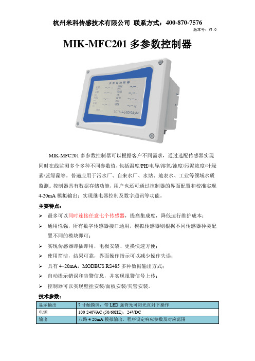
MIK-MFC201多参数控制器MIK-MFC201多参数控制器可以根据客户不同需求,通过选配传感器实现同时在线监测多个多种不同参数值,包括温度/PH/电导/溶氧/浊度/污泥浓度/叶绿素/蓝绿藻等。
普遍应用于污水厂、自来水厂、水站、地表水、工业等领域水质监测。
控制器具有数据存储功能,用户也还可通过控制器的界面配置和校准实现4-20mA模拟输出;实现继电器控制及数字通讯等功能。
主要特点:最多可以同时连接任意七个传感器,提高集成度,降低运行维护成本;通用性强,所有数字传感器接口通用,模拟传感器则根据不同传感器种类配置不同的模块即可;实现传感器即插即用,电极安装、更换快速方便;使用简洁,结果可靠,界面操作指示可以减少操作失误;具有4~20mA,MODBUS RS485多种数据输出方式;自动提示错误和告警信息,并实现报警信号上传;控制器可以实现壁挂安装/面板安装/夹管安装。
技术参数:SIN-DO700荧光法溶解氧传感器测量原理:SIN-DO700溶解氧传感器采用荧光法测量溶解氧,传感器顶端覆盖了一层荧光物质,当传感器发出的蓝光照射到荧光物质时,荧光物质受到激发发出红光,由于氧分子可以带走能量(猝熄效应),所以激发的红光的时间和强度与氧分子的浓度成反比,通过计算可得出水中溶解氧的浓度。
主要特点:传感器采用新型氧敏感膜,自带NTC温补功能,测量结果具有良好的重复性及稳定性;测量时不会产生氧消耗,没有流速/搅动要求;突破性的荧光技术,没有膜和电解液,基本无需保养;内设自诊功能,保证数据准确;出厂标定,一年无需校准,可现场标定;数字化传感器,抗干扰能力强,传输距离远;标准数字信号输出,可在无控制器的情况下实现和其他设备的集成和组网;传感器现场安装方便快捷,实现即插即用。
技术参数:LR-TP20浊度传感器测量原理:LR-TP20浊度传感器基于组合红外吸收散射光线法,光源发出的红外光经过样品中浊度的散射,最后由光电检测器转换为电信号,并经过模拟和数字信号处理后获得样品的浊度值。
林德 l20参数林德L20参数介绍林德L20是一款智能手机,具备强大的性能和多功能的操作系统。
下面将从外观设计、硬件配置、摄像头、操作系统和电池续航等方面详细介绍林德L20的参数。
外观设计林德L20采用了时尚简约的设计风格,机身采用金属材质打造,手感舒适且质感出众。
手机背面配备了指纹识别模块,确保用户的信息安全。
手机尺寸适中,便于单手操作,同时屏幕占比也较高,视觉效果出色。
硬件配置林德L20搭载了高性能的处理器,能够快速处理各种任务。
内存容量大,运行多个应用程序时不易出现卡顿现象。
存储空间也较大,用户可以存储大量的照片、视频和应用程序。
此外,林德L20还支持扩展存储,用户可以根据自己的需求进行扩展。
摄像头林德L20配备了高像素的前后摄像头,能够拍摄出清晰细腻的照片和视频。
后置摄像头具有自动对焦和光学防抖功能,能够在不稳定的场景下拍摄清晰的照片。
前置摄像头支持美颜功能,让自拍更加美丽。
操作系统林德L20采用了最新的操作系统,界面简洁直观,操作流畅。
操作系统还支持多任务处理,用户可以同时进行多项操作,提高工作效率。
此外,操作系统还具备丰富的应用程序资源,用户可以根据自己的需求下载安装各种应用程序。
电池续航林德L20具有较大容量的电池,能够满足用户一天的正常使用需求。
同时,手机还采用了智能省电技术,能够根据用户的使用习惯进行智能调节,延长电池的使用时间。
此外,林德L20还支持快速充电技术,用户只需要短时间就能充满电。
总结林德L20作为一款智能手机,具备了强大的性能和多功能的操作系统。
外观设计时尚简约,手感舒适且质感出众。
硬件配置强大,能够满足用户的各种需求。
摄像头拍摄效果出色,能够拍摄清晰细腻的照片和视频。
操作系统简洁流畅,支持多任务处理。
电池续航能力强,满足用户一天的正常使用需求。
综上所述,林德L20是一款非常优秀的智能手机,值得用户购买和使用。
vivox20和xplay6性价比哪个高?vivox20和xplay6参数配置比力vivox20和xplay6性价比哪个高?vivoxplay6和x20谁更加好用?vivox20和xplay6配置参数有什么区别?vivoxplay6和x20哪个值得买?vvivox20和xplay6买性价比哪个高呢?vivoxplay6和x20哪个性价比跟高?很多朋友问。
今天豌豆荚小编就为大家带来vivoxplay6和x20不同对标测评阐发,快来看看吧!vivox20先容:9月21日晚上,vivo北京庸关长城正式公布全新旗舰机——vivox20vivox20主打全面屏、高颜值、摄影、HiFi 音乐播放品德等,售价2998元。
vivox20还邀请了彭于晏、鹿晗、周冬雨强大代言阵容。
vivox20仍旧后面配置手指手指指纹辨认,值得一提的还支持FaceWake面部辨认。
首先看一下关于vivox20基础配置参数,以便对vivox20有个全面的解,以下图所示:设置装备摆设配置层面,vivox20组装有了和OPPOR11同款高通骁龙660八核处理器,功效定位中高端、组装有了6英寸2K全面屏、组装有后置两个摄像头、内部设置装备摆设HiFi 芯片、撑持FaceWake面部辨认,全部设置装备摆设层面的呈现还是不错的手机把持手机操作系统层面,vivox20利用了遵照7.1FuntouchOS3.2手机把持手机操作系统,配搭第三代智慧引擎,能够遵照用户的利用习性,智能识别用户罕用的系统,并优先分配更多的CPU 内置储存资本、让你操纵中更快速的策动系统,让手机越用越懂让你把持全部给人的操纵感到持续畅快同时斗劲省电。
颜值层面,vivox20与x9系列一样,仍然是一体手机操纵金属建造制作,供给金色、玫瑰金、磨砂黑三种配置颜色可选,由于利用了全面屏制造,让6英寸大屏手机,大小与5.5英寸旁边艰深手机差不多,并且机身纤薄颜值上还是斗劲好的vivox20手机前面组装有了6.01英寸2K超清屏幕,屏占比高达85.3与华为nova2一样,利用了189屏比制造,视觉攻击斗劲震动。
IP20防护等级表示:
1、防尘等级。
防止大于12mm的固体物体侵入,防止人的手指接触到灯具内部之零件,防止中等尺寸的外物侵入。
2、防水等级.。
是指对水或湿气无特殊的防护。
IP防护等级通常是由两个数字所组成,第1个数字表示电器防尘、防止外物侵入的等级,第2个数字表示电器防湿气、防水浸入的密闭程度,数字越大也就代表防护等级越高。
扩展资料:
防尘等级号码防护的定义如下:
(1)数字0表示无防护,无特殊的防护。
(2)数字1表示防止大于50mm之物体侵入,防止人体因不慎碰到电气设备内部零件,防止直径大于50mm之物体侵入;
(3)数字3表示防止大于2.5mm之物全侵入,防止直径大于2.5mm 的工具,电线或物体侵入;
(4)数字4表示防止大于1.0mm之物体侵入,防止直径大于1.0mm 的蚊蝇、昆虫或物体侵入;
(5)数字5表示无法完全防止灰尘侵入,但侵入灰尘量不会影响电气正常运作;
(6)数字6表示完全防止灰尘侵入。
20%的计算方法摘要:1.了解20%计算方法的背景和意义2.20%计算方法的具体步骤3.实例演示4.注意事项和实用技巧正文:在我们生活和工作中,经常会遇到需要计算20%的情况,例如税率、折扣等。
那么如何快速准确地计算20%呢?以下将详细介绍20%的计算方法。
首先,了解20%计算方法的背景和意义。
20%表示一个数占另一个数的百分之二十,通常用于表示比例、百分比、税率等。
在数学上,20%可以表示为0.2或2/10。
接下来,介绍20%计算方法的具体步骤。
1.确定基数:要计算20%,首先需要确定一个基数。
例如,如果需要计算商品折扣,那么商品的原价就是基数。
2.转换比例:将20%转换为小数或分数。
20%等于0.2,也可以表示为2/10。
3.乘以基数:将基数乘以20%的比例。
例如,如果商品原价为100元,折扣为20%,那么计算公式为:100 * 0.2 = 20。
这意味着商品折扣为20元。
4.实例演示:假设你购买了一件商品,原价为500元,商家承诺打八折。
那么,计算折扣金额:500 * 0.2 = 100。
因此,你将获得100元的折扣。
在实际计算过程中,还可以使用以下实用技巧:1.利用手机calculator 键计算:大部分手机键盘上都有一个calculator 键,可以直接输入0.2或2/10进行计算。
2.使用记忆技巧:20%可以记忆为“二十分之一”,这样在计算时可以快速转化为小数0.2。
3.注意事项:在进行20%计算时,请注意基数的选择。
有时题目中会隐藏基数,需要仔细阅读并提取出来。
总之,掌握20%的计算方法非常简单,只需将基数乘以20%的比例即可。
植物源杀菌剂20%丁香酚水乳剂对草莓灰霉病的田间防治效果
作者:张猛
来源:《江苏农业科学》2015年第01期
摘要:采用温室大棚内随机区组小区试验,以50%腐霉利可湿性粉剂为对照药剂,研究了植物源农药20%丁香酚水乳剂对草莓灰霉病的田间防效。
结果表明,植物源杀菌剂20%丁香酚水乳剂 300、375 g a.i./hm2对草莓灰霉病具有较好的防治效果,明显高于对照药剂50%腐霉利可湿性粉剂 1875 g a.i./hm2,同时对草莓生长安全;第3次施药后,20%丁香酚水乳剂 225 g a.i./hm2+50%腐霉利可湿性粉剂 750 g a.i./hm2防效极显著高于20%丁香酚水乳剂 300 g a.i./hm2 处理(P
关键词:草莓灰霉病;丁香酚;植物源杀菌剂;防治效果
中图分类号:S482.2+92文献标志码: A文章编号:1002-1302(2015)01-0132-02
收稿日期:2014-08-31
基金项目:江苏省农业科技自主创新资金[编号:CX(12)5041]。
作者简介:张猛(1982—),男,山东泰安人,博士,助理研究员,主要从事植物源农药抑菌机理研究。
Tel:(025)84391863;E-mail:z320m320@。
灰霉病是草莓上发生的主要病害之一,分布广泛,在草莓全生育期均可发病,叶柄、叶片、花蕾、花瓣、果柄、果实都可感染,但主要是在开花后发生,是造成烂果的主要原因,一般减产10%~30%,重者在50%以上,严重阻碍了草莓生产发展。
目前,用于防治灰霉病的化学药剂主要有苯并咪唑类、二甲酰亚胺类和N-苯氨基甲酸酯类,长期大量使用这几类杀菌剂,可造成灰霉病对多种药剂产生不同程度抗药性[1-5],化学农药残留对环境的污染等问题使得化学药剂防治已不能达到人们对环境保护和食品安全的要求。
采用高效、低毒、环境友好的植物源农药来替代传统化学农药防治灰霉病是草莓生产中亟待解决的问题。
丁香酚主要存在于丁香油、肉桂叶油、肉桂皮油、樟脑油、肉豆蔻油等中,对真菌引起的病害均有很好的防治作用,对植物灰霉病有较好防治效果,且高效、低毒、无公害、无残留、不污染环境、不影响农产品品质。
本研究以腐霉利为对照药剂,研究植物源杀菌剂丁香酚对草莓灰霉病的田间防治效果,旨在为该药剂的推广应用提供依据。
1材料与方法
1.1材料
供试药剂:20%丁香酚水乳剂,江苏省农业科学院食品质量安全与检测研究所投入品项目组研制;50%腐霉利可湿性粉剂,上海农安生物科技发展有限公司生产。
草莓品种:宁玉、红颊,由江苏省农业科学院园艺研究所提供。
1.2试验设计
试验设20%丁香酚水乳剂 300、375 g a.i./hm2,20%丁香酚水乳剂 225 g a.i./hm2+50%腐霉利可湿性粉剂 750 g a.i./hm2,50%腐霉利可湿性粉剂 1 875 g a.i./hm2,以喷施清水为空白对照,共设5个处理,每处理4次重复,每个小区面积20 m2,共20个小区。
1.3试验方法
试验田位于泗洪县魏营镇草莓基地,试验田为大棚草莓连作田,2012年8月25日定植,双膜大棚越冬,土壤质地为黏土,肥力上等,pH值 7.2左右。
试验期间共施药3次,每隔7 d 左右喷1次,时间分别为12月6日、13日、20日。
12月6日首次施药时灰霉病零星见病,草莓处于结果期。
采用工农16型背负式手动喷雾器,用水量750 L/hm2。
1.4调查统计方法
分别于第1次施药前调查病情基数,第2、3次施药后7 d(12月27日)调查各小区草莓果实病情。
每小区5点双行跳跃取样,每点定10株草莓,调查总果数和病果病级数,计算防病效果。
对防病效果进行方差分析,各处理间采用Duncans新复极差法进行多重比较。
施药后不定期观察草莓的生长发育情况,以明确药剂对草莓的安全性。
病害分级方法及病情指数、防治效果计算公式如下。
病害分级标准:0级,叶片、果实无病斑;1级,病斑面积占整个叶片、果实面积的1%以下;3级,病斑面积占整个叶片、果实面积的2%~5%;5级,病斑面积占整个叶片、果实面积的6%~20%;7级,病斑面积占整个叶片、果实面积的21%~40%;9级,病斑面积占整个叶片、果实面积的40%以上。
病情指数=[∑(各级病叶、果×该病级值)/(调查总叶、果数×最高病级值)]×100;防治效果=[(对照区病情指数-处理区病情指数)/对照区病情指数]×100%。
2结果与分析
2.1对草莓灰霉病的防治效果
由表1可知,20%丁香酚水乳剂 300、 375 g a.i./hm2,20%丁香酚水乳剂 225 g
a.i./hm2+50%腐霉利可湿性粉剂 750 g a.i./hm2,在第2次施药后7 d防病效果分别为8112%、
77.91%、76.58%,对照药剂50%腐霉利可湿性粉剂1 875 g a.i./hm2的防效为62.80%;第3次施药后7 d 各处理防病效果分别上升至83.16%、88.98% 、86.14%,对照药剂上升为74.80%。
由表2可知,20%丁香酚水乳剂 300、375 g a.i./hm2,20%丁香酚水乳剂 225 g
a.i./hm2+50%腐霉利可湿性粉剂 750 g a.i./hm2,在第2次施药后7 d防病效果分别为7856%、
83.04%、77.12%,对照药剂50%腐霉利可湿性粉剂 1 875 g a.i./hm2的防效为63.28%;第3次施药后7 d 各处理防病效果分别上升到84.55%、89.12% 、88.01%,对照药剂上升为77.23%。
表120%丁香酚对宁玉草莓灰霉病的防治效果
2个草莓品种在相同环境条件下对灰霉病感病程度不同,红颊比宁玉严重;在2次施药后,对照药剂防效极显著低于丁香酚药剂处理,可能与该地区长期使用该类药剂,草莓灰霉病菌对此类药剂产生抗药性有关;第3次施药后,20%丁香酚水乳剂 225 g a.i./hm2+50%腐霉利可湿性粉剂 750 g a.i./hm2 防效显著高于20%丁香酚水乳剂 300 g a.i./hm2 处理,防效与20%丁香酚水乳剂 375 g a.i./hm2 处理相近,表明丁香酚与腐霉利混用对草莓灰霉病具有较好的防治效果。
2.2草莓安全性调查
施药后不定期观察草莓生长情况,各处理草莓生长发育正常,未见任何不良影响,表明安全性较好。
3结论与讨论
由灰葡萄孢菌引起的草莓灰霉病是目前草莓生产中的主要病害。
本试验调查发现不同的草莓品种对灰霉病的感病程度不同,选用感病低的草莓品种能够在同样的栽培管理条件下减少灰霉病对草莓的危害。
迄今为止,尚未发现对灰霉病具有免疫能力的草莓品种,因此采用化学防治是控制灰霉病的主要措施之一[6-7]。
草莓灰霉病敏感生育期为开花坐果期至采收期,用药最佳时期在草莓第1花序有20%以上开花、第2花序刚开花时,但是草莓花期用药易产生畸形果,果实期用药易造成果实污染等问题。
近年来,植物源农药因为具有低毒、环境友好、对靶标不易产生抗性等优点而受到人们的青睐[8-9]。
田间试验示范表明,20%丁香酚水乳剂 300、375 g a.i./hm2 对草莓灰霉病均有较理想的防治效果,显著高于对照药剂50%腐霉利可湿性粉剂1 875 g a.i./hm2的防效。
但是植物源药剂也存在着药效发挥慢、当病害大面积暴发时很难及时控制病情发展,用药成本比化学农药高等问题。
本试验在第3次施药后,20%丁香酚水乳剂225 g a.i./hm2+50%腐霉利可湿性粉剂 750 g a.i./hm2防效高于20%丁香酚水乳剂 300 g a.i./hm2 处理,防效与20%丁香酚水乳剂 375 g a.i./hm2 处理相近,表明丁香酚与腐霉利混用对草莓灰霉病具有较好的防治效果。
采用化学农药与植物源农药混用或者交替使用技术,结合化学农药的速效性的特点,既可快速有效控制病害蔓延,又能减少化学农药对环境污染、农药残留,并可节约用药成本,符合目前农民对农产品无公害生产和增产增收的要求,可以作为田间防治草莓灰霉病的一种用药模式进行推广应用。
参考文献:
[1]周明国,叶钟音,杭建胜,等. 对多菌灵具有抗性的草莓灰霉病菌菌株形成于分布研究[J]. 南京农业大学学报,1990,13(3):57-60.
[2]刘波,叶钟音,刘经芬,等. 对多菌灵、速克灵具多重抗性的灰霉病菌菌株性质的研究[J]. 南京农业大学学报,1993,16(3):50-54.
[3]纪明山,程根武,张益先,等. 灰霉病菌对多菌灵和乙霉威抗性研究[J]. 沈阳农业大学学报,1998,29(3):213-216.
[4]纪明山,祁之秋,王英姿,等. 番茄灰霉病菌对嘧霉胺的抗药性[J]. 植物保护学报,2003,30(4):396-400.
[5]张传清,张雅,魏方林,等. 设施蔬菜灰霉病菌对不同类型杀菌剂的抗性检测[J]. 农药学学报,2006,8(3):245-249.
[6]赵密珍,余桂红,钱亚明,等. 草莓品种灰霉病抗性田间鉴定[J]. 植物遗传资源科学,2002,3(4):36-38.
[7]杨敬辉,陈宏州,吴琴燕,等. 啶酰菌胺对草莓灰霉病菌的毒力测定及田间防效[J]. 江西农业学报,2010,22(9):94-95,98.
[8]张应烙,尹彩薄. 植物源杀菌剂的研究进展[J]. 西南民族大学学报,2005,31(3):402-408.
[9]沐祥,吴祥,束兆林,等. 新型植物源杀菌剂20%乙蒜·丁子香酚可湿性粉剂防治草莓灰霉病试验[J]. 农药,2010,49(6):458-459.陈燕,谢红辉,黄凤宽,等. 四斑广盾瓢虫成虫对桃蚜的捕食功能反应[J]. 江苏农业科学,2015,43(1):134-136.。