The Structure of Projected Center Vortices in Lattice Gauge Theory
- 格式:pdf
- 大小:212.40 KB
- 文档页数:18

精选文档2014 年下半年高中《英语学科知识》教师资格证考试统考真题及答案一、选择题(本大题共30 小题,每题 2 分,共60 分)在每题列出的四个备选选项中选择一个最正确答案,请用2B 铅笔把答题卡上对应题目的答案字母按要求涂黑。
错选、多项选择或未选均无分。
of the following is the proper pronunciation of “ have to“as a result of assimilation?A. / hef tu /B. / hev tu /C. / h?f tu /D./ h? v tu /of the following shows the proper rhythmical pattern of the sentence?A. ′ Come to ′ see us at our ′ new a`partmentB.`Come to`see us at`our new`apartmentC.`Come to`see us`at our`new`apartmentD.`Come to`see us`at our`new a`parementcame to dinner and my mom fixed a roast,prime rib,pie,yohurt,dri nks,and that kind of _,and it was really good.her _sister,Judith is a shy,unsociable person who dislike to go to parties or to make new friends.pledged support for “_ care ”,where youngsters were looked after be close relatives like aunts or uncles,but not parents.will never know all that was in his head at the time,_ .will anyone else anyone else willwon′ t anyone else anyone else won′ tdoesn′t want to work right now because she thinks that if she_a job she probably wouldn ′t be able to visit her friends very often.to get to get got have gotis the correct way to read the decimal “ 106.16 ” in English?hundred and six point one hundred and six point six teenhundred and six points one six hundred and six points s ixteenany of the maxims under the Cooperative Principle is floutedon purpose,might arise.精选文档structure propositionunderstanding implicatureEnglish is a_ variety of the English language.teaching pronunciation,the teacher should tell the students that_can be used to convey more important messages.a teacher asks students to discuss how the writer ˊs ideas are organized in the text,he/she intends to develop studentsˊskill of _ .of the following focus(es)on accuracy in teaching grammar?drillsplaya teacher says“Next,please pay attention to the time of arrival and departure ofthe planes in the recording.”,he / she intends to develop students'skill of _ .the general picturesounds specific informationa teacher asks students to list as many ways as they can to tell someone to open the door and list the possible functions ofa sentence in different/she is probably trying to highlight_.teacher would use_to help students communicate in teaching speaking.drills discussionand acting aloud17. _assessment is used to measure how the performance of a particular st udent or group of students compares with that of another.of the following teacher's instruction could serve the purpose of eliciting ideas?we move after me,everyonecan you see in this picture does the world“ quickly”mean?of the following is an example of teachers 'indirect corrective feedback?A.Say “ went ” instead of “go”never use “ at ” that wayA is not the right answer can help him with this se ntence?Physical Response as a TEFL method is more often used for teaching_.course course请阅读 passage1, 达成第21~25小题Passage1Unless you spend much time sitting in a college classroom or browsin g through certain areas of the Internet,it's possible that you had not heard of trigger warnings until a few weeks ago,when they made an appearance in the newspaper exp lained that the term refers to preemptive alters,issued by a professo r or an class might be sufficiently graphic to spark symptoms of po st-traumatic-stress disorder.The term seems to have originated in online feminist forums,where tri gger warnings have for some years been used to flag discussion of r ape or other sexual Times piece,which was skeptically tit led“warnings are moving from the online fringes to the classroom,and mi ght be more broadly applied to highlight in advance the distress or offense that a work of literature might cause. “ Huckleberry Finn ”would come with a warning for those who have experienced racism;The Merchant of Venice would have an anti-Semitism warning ca ll from students for trigger warnings was spreading on campuses such as Oberlin,where a proposal was drafted that would advise professors to“be aware of racism,classism,sexism,and other issues of privilege and oppression”in devising their syllabi;and Rutgers,where a student argued in the c ampus newspaper that trigger warnings would contribute to preserving t he classroom as a“ safe space ” for students.Online discussion of trigger warnings has sometimes been guardedly sym pathetic,sometimes Valenti has noted on The Nation 's website that potential triggers for trauma are so manifold as tobe beyond the possibility of cataloguing:“There is no triggers for warning for living your life.”Some have suggested that a professor's ability to teach would be compromised should it become commonplace for“ The Great Gatsby ”to hear a trigger warning alerting readers to the disgusting characte rs and incidents within its have worried that trigger-warning advocates,in seeking to protect the vulnerable,run the risk of d isempowering them instead,“Bending the world to accommodate our personal frailties does not he lp us overcome them” ,Jenny Jarvie wrote on The New Republic's online site.Jarvie's piece,like many others on the subject,cited the University of Calif ornia,Santa Barbara,as a campus where champions of trigger warnings ha ve made significant this year,students atd upon a resolution recommending that such warnings be issued in ins tances where classroom materials might touch upon“rape,sexual assault,abuse,self-injurious behavior,suicide,and graphic vio lence ” .The resolution was brought by a literature student who said t hat,as a past victim of sexual violence,she had been shocked when a teacher showed a movie in class which depicted rape,without giving advance notice of the student hoped to spare others the possibility of experiencing a post-traumatic-stress reaction.The trigger-warning debate may,by comparison,seem hard to understand;but express a large cultural preoccupation with achieving safety,and a f ear of living in its hope that safety might be found,asin a therapist's office,in a classroom where literature is being taught is in direc t contradiction to one purpose of literature,which is to give express ion through art to difficult and difficult and uncomfortable ideas,and thereby to enlarge safe space,nor,probably,should it it's difficult to fault those who hope that it might be,when the outsi de world constantly proves itself pervasively hostile,as well as,on oc casion,horrifically violent.of the following groups of people are most in favor of “trigger warning ” ?of the following might be a possible change to be brought about by trigger warning to literature teaching?will abandon materials related to racism,sexism,violence,etc.will ignore students' s requests for a“ safe space ”in designing their syllabi.will give students advance notice of the content that is likely to distress or offend them.will allow students to express different and uncomfortable ideas to enlarge their experience.does the author mean by“ compromised ” in PARAGRAPH3?24.What does“ them” in PARAGRAPH3refer to?of the following can be the negative impact that trigger wa rning exerts on literature teaching according to the writer?may highlight the purpose of literature teaching.may expose students to the dark side of the world.may deprive students of their intellectual growth.may cause students to experience a post-traumatic-stress disorder.请阅读 passage2, 达成 26~30小题。

Giant StructuresIt is an impossible task to select the most amazing wonders of the modem world since every year more __1__ constructions appear. Here are three giant structures which are worthy of our __2__ although they may have been surpassed by some more recent wonders.The Petronas Twin TowersThe Petronas Towers were the tallest buildings in the world when they were completed in 1999. With a __3__ of 452 metres, the tall twin towers, like two thin pencils, dominate the city of Kuala Lumpur. At the 41st floor, the towers are linked by a bridge, symbolizing a gateway to the city. The American __4__ Cesar Pelli designed the skyscrapers.Constructed of high-strength concrete, the building provides around 1,800 square metres of office space __5__ every floor. And it has a shopping centre and a concert hall at the base. Other __6__ of this impressive building include double-decker lifts, and glass and steel sunshades.The MiUau BridgeThe Millau Bridge was opened in 2004 in the Tam Valley,in southern France. __7__ the time it was built,it was the world’s highest bridge, __8__ over 340m at the highest point. The bridge is described as one of the most amazingly beautiful bridges in the world. It was built to __9__ Millau's congestion problems. The congestion was then caused by traffic passing from Paris to Barcelona in Spain. The bridge was built to withstand the __10__ extreme seismic and climatic conditions. Besides, it is guaranteed for 120 years!The Itaipu DamThe Itaipu hydroelectric power plant is one of the largest constructions of its kind in the world. It consists of a series of dams across the River Parana, __11__ forms a natural border between Brazil and Paraguay. Started in 1975 and taking 16 years to complete, the construction was carried out as a joint project between the two __12__. The dam is well-known for both its electricity output and its size. In 1995 it produced 78% of Paraguay’s and 25% of Brazil’s __13__ needs. In its construction, the __14__ of iron and steel used was equivalent to over 300 Eiffel Towers. It is a __15__ amazing wonder of engineering.Why India Needs Its Dying VulturesThe vultures in question may look ugly and threatening, but the sudden sharp __1__ in three species of India’s vultures is producing alarm rather than celebration, and it presents the world with a new kind of environmental __2__ The dramatic decline in vulture numbers is causing widespread disruption to people living in the same areas as the __3__ . It is also causing serious public health problems __4__ the Indian sub-continent.While their reputation and appearance may be unpleasant to many Indians,vultures have__5__played a very important role in keeping towns and villages all over India clean. It is__6__they feed on dead cows. In India, cows are sacred animals and are __7__ left inthe open when they die in their thousands upon thousands every year.The disappearance of the vultures has __8__ an explosion in the numbers of wild dogs feeding on the remains of these dead animals. There are fears that rabies may __9__ as a result. And this terrifying disease may ultimately affect humans in the region, since wild dogs are its main carriers. Rabies could also spread to other animal species, causing an even greater problem in the __10__.The need for action is __11__, so an emergency project has been launched to __12__ a solution to this serious vulture problem. Scientists are trying to identify the disease causing the birds,deaths and, if possible, develop a cure.Large-scale vulture __13__ were first noticed at the end of the 1980s in India. A population survey at that time showed that the three species of vultures had declined __14__ over 90 per cent. All three species are now listed as “critically endangered”. As most vultures lay only single eggs and __15__ about five years to reach maturity, reversing their population decline will be a long and difficult exercise.Better Solar Energy Systems: More Heat, More LightSolar photovoltaic thermal energy systems, or PVTs, generate both heat and electricity, but __1__ now they haven’t been very good at the heat-generating part compared to a stand-alone solar thermal collector. That’s because they operate at low temperatures to cool crystalline silicon solar cells, which lets the silicon generate more __2__ but isn’t a very efficient way to gather heat.That’s a problem of __3_ . Good solar hot-water systems can harvest much more energy than a solar-electric system at a substantially lower __4__. And it,s also a space problem:photovoltaic cells can take up all the space on the roof, leaving little room for thermal applications.In a pair of studies, Joshua Pearce, an associate professor of materials science and engineering, has devised a __5__ in the form of a better PVT made with a different kind of silicon. His research collaborators are KunalGirotra from ThinSilicon in California and Michael Pathak and Stephen Harrison from Queen’s University, Canada."Most solar panels are made with crystalline silicon,but you can also make solar cells out of amorphous silicon, __6__ known as thin-film silicon. They don’t create as much electricity, but they are lighter, flexible, and cheaper. And, because they __7__ much less silicon, they have a greener footprint. Unfortunately,thin-film silicon solar cells are __8__ to some bad-news physics in the form of the Staebler-Wronski effect.“That means that their efficiency __9__ when you expose them to light —pretty much the worst possible effect for a solar cell,”Pearce explains,which is one of the __10__ thin-film solar panels make up only a small fraction of the market.However, Pearce and his team found a way to engineer around the Staebler-Wronski effect by incorporating thin-film silicon in a new __11__ of PVT. You don’t have to cool down thin-film silicon to make it work. In fact,Pearce’s group discovered that by heating it to solar-thermal operating temperatures,near the boiling __12__ of water, they could make thicker cells that largely __13__ the Staebler-Wronski effect. When they applied the thin-film silicon directly to a solar thermal energy __14__ , they also found that by baking the cell once a day,they __15__ the solar cell’s electrical efficiency by over 10 percent.Chicken Soup for the Soul:Comfort Food Fights LonelinessMashed potatoes, macaroni and cheese, may be bad for your arteries.1 according to a study in Psychological Science, they’re good for your heart and 2 .The study focuses on “comfort food”and how it makes people feel."For me 3 ,food has always played a big role in my family,”says Jordan Troisi, a graduate student at the University of Buffalo, and lead author on the study.The study came out of the research program of his co—author Shira Gabriel.It has 4 non-human things that may affect human emotions.Some people reduce loneliness by bonding with their 5 TV show, building virtual relationships with a pop song singer or looking at pictures of loved ones.Troisi and Gabriel wondered if comfort food could have the same effect 6 making peoplethink of their nearest and dearest. In one experiment, in order to make 7 feel lonely, the researchers had them write for six minutes about a fight with someone close to them.Others were given an emotionally neutral writing assignment. Then, some people in each 8 wrote about the experience of eating a comfort food and others wrote about eating a new food.9 ,the researchers had participants 10 questions about their levels of loneliness.Writing about a fight with a close person made people feel lonely.But people who were generally 11 in their relationships would feel less lonely by writing about a comfort food."We have found that comfort foods are consistently associated with those close to us."says Troisi."Thinking about or consuming these foods later then serves as a reminder of those close others."In 12 essays on comfort food, many people wrote about the 13 of eating food with family and friends. In another experiment, 14 chicken soup in the lab made people think more about relationships, but only if they considered chicken soup to be a comfort food.This was a question they had been asked long before the experiment, along with many other questions, so they wouldn’t remember it. Throughout everyone’s daily lives they experience stress, often associated with our 15 with others," Troisi says."Comfort food Can be an easy remedy for loneliness.。
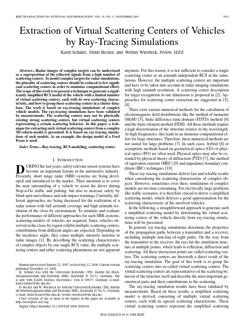
Extraction of Virtual Scattering Centers of Vehicles by Ray-Tracing SimulationsKarin Schuler,Denis Becker,and Werner Wiesbeck,Fellow,IEEEAbstract—Radar images of complex targets can be understood as a superposition of the reflected signals from a high number of scattering centers.To model complex targets for radar simulations, the plurality of scattering centers should be reduced to few signifi-cant scattering centers in order to minimize computational effort. The scope of this work is to present a technique to generate a signif-icantly simplified RCS model of the vehicle with a limited number of virtual scattering centers,each with its own scattering charac-teristic,and how to group these scattering centers in a cluster data-base.The work is based on ray-tracing simulations of complex vehicle models.The ray-tracing simulations have been validated by measurements.The scattering centers may not be physically existing strong scattering centers,but virtual scattering centers representing a certain scattering behavior.In this paper,a tech-nique for extracting such virtual scattering centers from a complex 3D-vehicle-model is presented.It is based on ray-tracing simula-tions of such models.As an example,the design model of a Ford Focus is used.Index Terms—Ray-tracing,RCS-modeling,scattering center.I.I NTRODUCTIOND URING the last years,safety relevant sensor systems havebecome an important feature in the automotive industry. Presently,short range radar(SRR)systems are being devel-oped and introduced to the market.Their intention is to cover the near surrounding of a vehicle to assist the driver during Stop-n-Go traffic and parking,but also to increase safety by blind-spot surveillance and side impact warnings.Currently,dif-ferent approaches are being discussed for the realization of a radar sensor with full azimuth coverage and high azimuth res-olution of the close-by environment.To simulate and evaluate the performance of different approaches for such SRR-systems, scattering-models of vehicles are required.Since vehicles ob-served in the close-by region exhibit multiple scattering centers, contributions from different angles are expected.Depending on the incidence angle,they cause multiple intensity maxima in radar images[1].By describing the scattering characteristics of complex objects by one single RCS value,the multiple scat-tering centers and other scattering phenomena are not apparentManuscript received January22,2007;revised July12,2008.Current version published November14,2008.K.Schuler was with the Universität Karlsruhe(TH),Institut für Höch-stfrequenztechnik und Eletronik(IHE),Karlsruhe D76131,Germany.She is now with EADS Defence Electronics,Ulm D89077,Germany(e-mail: karin.schuler@a.de).D.Becker and W.Wiesbeck are with the Universität Karlsruhe(TH),Institut für Höchstfrequenztechnik und Eletronik(IHE),Karlsruhe D76131,Germany (e-mail:denis.becker@a.de;werner.wiesbeck@a.de).Color versions of one or more of thefigures in this paper are available at .Digital Object Identifier10.1109/TAP.2008.2005436anymore.For this reason,it is not sufficient to consider a single scattering center or an azimuth independent RCS in the simu-lations.However,the multiple scattering centers are important and have to be taken into account in radar imaging simulations with high azimuth resolution.A scattering center description for target recognition in one dimension is proposed in[2].Ap-proaches for scattering center extraction are suggested in[3], [4].There exist various numerical methods for the calculation of electromagneticfield distributions like the method of moments (MoM)[5],finite-difference-time-domain(FDTD)method[6] and thefinite element method(FEM).All these methods require a high discretization of the structure relative to the wavelength. At high frequencies,this leads to an immense computational ef-fort for large structures.Therefore,these numerical methods are not suited for large problems[7].In such cases,hybrid[8]or asymptotic methods based on geometrical optics(GO)or phys-ical optics(PO)are often used.Physical optics may also be ex-tended by physical theory of diffraction(PTD)[7],the method of equivalent currents(MEC)[9]and impedance boundary con-dition(IBC)techniques[10].These ray-tracing simulations deliver fast and reliable results when considering the scattering characteristic of complex ob-jects.However,sometimes even these simulations of complex models are too time-consuming.For electrically large problems like traffic scenarios,it is therefore crucial to derive a simplified scattering model,which delivers a good approximation for the scattering characteristic of the involved vehicles.In the following,a straightforward approach to generate such a simplified scattering model by determining the virtual scat-tering centers of the vehicle directly from ray-tracing simula-tions will be presented.In general,ray-tracing simulations determine the properties of the propagation paths between a transmitter and a receiver, including multiple non-line-of-sight paths.On the way from the transmitter to the receiver,the rays hit the simulation struc-ture at multiple points,which leads to reflection,diffraction and scattering.All these interaction points are called scattering cen-ters.The scattering centers are therewith a direct result of the ray-tracing simulation.The goal of this work is to group the scattering centers into so-called virtual scattering centers.The virtual scattering centers are representatives of the scattering be-havior of the structure itself and describe the most important ge-ometrical parts and their contributions to the scattering.The ray-tracing simulation results have been validated by measurements.Based on these results,a simplified scattering model is derived,consisting of multiple virtual scattering centers,each with its special scattering characteristic.These virtual scattering centers represent the simplified scattering0018-926X/$25.00©2008IEEEFig.1.Model of Ford Focus for IHE3D-ray-tracing.Fig.2.Coordinate system.model,which has a similar scattering behavior as the complex car model.This simplified scattering model allows the rapid investigation of a wide range of radar scattering situations,where a conventional ray-tracing method would be too complex or is not available.II.R AY -T RACING S IMULATIONSimulations of vehicles with commercial FDTD simulation tools are not feasible at frequencies of 24GHz or 76GHz,as they are specified for automotive radar applications.The dis-cretization of the model into sub-wavelength-elements would lead to too large matrices.Ray-tracing simulations do not suffer directly from this constraint.The crucial number for ray-tracing-simulations is the number of visible faces seen by the trans-mitter.This number is therewith rather related to the geometry’s complexity than to its size.RCS simulations with ray-tracing have also been presented in [7].One approach for the determination of scattering centers is presented in [11].In simulated ISAR images intensity maxi-mums are considered as scattering centers and subtracted from the radar image with the clean algorithm [12].The radar images are based on the shooting and bouncing ray technique and on the processing of ISAR images.This procedure therefore requires a detour when processing the ISAR image.A similar but frequency and aspect dependent technique for data compression of SAR and ISAR images is presented in [13].It is based on the extraction of point and line-segment scatterers from the measured radar image.In the following,the scattering information obtained by the ray-tracing simulation will be directly evaluated.The usedray-Fig.3.Example of bistatic ray-tracing simulation with IHE3D-ray-tracing.Fig.4.Bistatic measurements at JRC,Ispra,Italy,car outside the chamber.tracing tool has been developed at the Institut für Höchstfre-quenztechnik und Elektronik (IHE)at the University of Karl-sruhe (TH)in Germany.It is a ray optical approach for modeling wave propagation.Each ray is considered separately and takes into account multiple reflections,diffraction and scattering.This gives an insight to the scattering centers and the scattering phe-nomena that will be exploited in the following.Modified Fresnel coefficients are used to model rough surfaces.Diffraction is de-scribed by the uniform geometrical theory of diffraction (UTD)and the corresponding heuristic coefficients for wedge diffrac-tion.The ray-tracing tool has already been verified multiple times with measurements for various wave propagation simu-lations [14]–[17].The 3D-model of the car,which is considered in the fol-lowing,is illustrated in Fig.1.The model of the car consists of 12.100triangles.Each ofthem is at least25,guaranteeing a large area compared to the wavelengthat .This is important to fulfill the requirements of the ray-tracing tool.For calculating the reflections,the ray-tracing tool assumes rel-atively large areas and uses the modified Fresnel-coefficients for the calculation of the reflection coefficient.Therefore,the edgeSCHULER et al.:EXTRACTION OF VIRTUAL SCATTERING CENTERS OF VEHICLES3545Fig.5.Bistatic coupling coefficient for front illumination ('=180)in vertical polarization at f =24GHz .Left:measurement,right:simulation.Fig.6.Bistatic coupling coefficient at elevation angle =60for rear illumination ('=0).Left:vertical polarization,right:horizontal polarization.length of an element must be within 5to 10wavelength,which is fulfilled in this case.This condition determines also the max-imum number of elements.In this particular case of a vehicle,reflections are the majority of all interactions.If the number of elements is chosen significantly smaller,the ray-tracer will not find enough reflections to represent the scattering character-istic of the car precisely enough.This would also be the case for lower frequencies,for which the size of the triangles would have to be increased and therefore their number would become to small to give a precise representation of the cars geometry.For higher frequencies,more detailed models could be used,delivering even more accurate results.A material assignment is made for each discretization element of the car.It contains the parameters of the permittivity,the roughness and the loss.For the simulation,a ground floor was added to take multipath propagation effects also into account [18].III.V ERIFICATION OF R AY -T RACING S IMULATIONSThe bistatic scattering coefficient of a Ford Focus has been simulated with ray-tracing and compared to measurements of the same vehicle.In Fig.2the coordinate system and its origin is defined relative to the car.Fig.3shows the top view for a bistatic ray-tracing simulation.The lines indicate the propagation paths.The line-of-sight path is neglected.For each transmitter and receiver position,the dynamic range is limited to 100dB with reference to the strongest non-line-of-sight path.Up to five interactions as diffraction and reflection are considered per path.For scattering only one interaction is considered,since the power level of the scattered path is reduced drasti-cally.For each path,the path information is stored.The path information contains the number,types and locations of the interactions.Also the amplitude and the phase of the received signals are delivered.These parameters are obtained from the propagation time and the complex scattering coefficients of the interactions.The vehicle is illuminated from therearin the azimuthplane whereas the receiver performs a 360-turn along the azimuth.The simulations have been per-formed for both horizontal and vertical polarization.Similar simulations were performed for frontillumination .The same configurations are used in the verification measure-ments.The verification measurements were performed in the ane-choic chamber of the European Commission Joint Research Center (JRC),located at Ispra in northern Italy,and were pub-lished in [19].Fig.4shows the vehicle in front of the anechoic chamber.3546IEEE TRANSACTIONS ON ANTENNAS AND PROPAGATION,VOL.56,NO.11,NOVEMBER 2008With this setup,the bistatic coupling coefficient along the az-imuthangle and the elevationangle has been measured for the two cases:front and rear illumination,both in vertical and horizontal polarization.The coupling coefficient for front illu-mination has been simulated and measured along a spherical surface.It is plotted along the azimuthangle and the eleva-tionangle .In Fig.5the comparison between measurement and simulation is shown for vertical polarization.The transmitantenna was placed at azimuthangleand elevationangle .The receive antenna was moved along azimuthfromto and along elevationfromto in the upper hemisphere.Measurements have alreadybeen performed for the study presented in [19]with an angular step width of 5along azimuth and elevation.For the compar-ison between the measurement and the simulation,the bistatic simulations have been performed with the same step width.The comparisons show a good agreement for high elevationangles,which are close to the azimuth plane.The farther transmitter and receiver are positioned from each other,the more simulation and measurement differ from each other.However,the closer transmitter and receiver are positioned to each other,the better is the agreement.Since in the following only monostatic simulations will be analyzed,reliable results from these ray-tracing simulations are expected.For a closer look at the data,the coupling coefficient for aconstant elevationangleis shown in Fig.6.It shows the comparison of the simulated and the measured coupling co-efficient for rear illumination in vertical (left)and horizontal (right)polarization.For both polarizations,the coupling coef-ficient drops significantly when transmit and receive antennasareorientedrelative to each other.The agreement be-tween measurement and simulation is very good for azimuthanglebetweenand 160.For azimuth angles closeto ,the angle of reflection is relatively large.In this spe-cific configuration,the simulation leads to an increased reflec-tion coefficient since the coupling along the roof of the car is considered to strong.The here presented comparison uses a bistatic configuration due to the available measurements.It shows,that the closer transmit and receive antenna are situated to each other,the better is the agreement between simulation and measurement.This is important since the following simulations and the derivation of the virtual scattering model will be performed in monostatic configuration.This monostatic configuration can be looked at as the extreme case of a bistatic configuration,where both an-tennas are placed at the same location.However,the accuracy of the virtual scattering center model can not be higher than the accuracy of the initial ray-tracing simulation.This comparison proves the reliability of the ray-tracing simulations with this de-tailed simulation model of the Ford Focus.Therefore the anal-ysis of ray-tracing specific information like the location of scat-tering centers and the path information can be used for further analysis.IV .M ONOSTATIC V IRTUAL S CATTERING C ENTER E XTRACTION In the following,monostatic ray-tracing simulations in az-imuth will be evaluated.The analysis of the scatteringcentersFig.7.Scattering centers for monostatic simulation of FordFocus.Fig.8.Flowchart of implemented greedy-algorithm.leads to scattering clusters.To each cluster,a single virtual scat-tering center with its own scattering characteristic is assigned.The scattering characteristic is obtained by summarizing the scattering effects of all scattering centers belonging to one cluster.Of course,a high number of clusters will lead to a more precise model,but on the other hand,a model containing a low number of clusters will result in a faster calculation.It will be shown that it is possible to reduce the complex vehicle model to a limited number of clusters for characterizing the scattering behavior in the azimuth plane without compromising on the precision of the simulation.A.Simulation of Scattering CentersA monostatic simulation of the reflection coefficient has been performed along azimuth using 1step width along a circle withtheradius.Regarding the possible application of this model for Short Range Radar simulations,the angular resolution width is a good compromise between computation time and ac-curacy.The position and the amplitude of the scattering centers depend on the radius and the azimuth angle during ray-tracing simulation.This fact has to be taken into account when the de-rived virtual scattering center model will be used in other radar simulations by calculating the aspect angles for each cluster and the attenuation.In Fig.7,the scattering centers for a monostatic simulationin vertical polarization for elevationangleand azimuth angle varyingfromto are plotted onto the carSCHULER et al.:EXTRACTION OF VIRTUAL SCATTERING CENTERS OF VEHICLES3547Fig.9.Adaptive clustering for size and shape.Left:circle middle:rectangle across.Right:rectangleupright.Fig.10.Shape moving of original position(dashed)tofind optimumfit posi-tion(solid).as black dots.Each scattering center is active for a certain di-rection with a specific amplitude and phase.This diagram illus-trates the important parts of the vehicle regarding the scattering in general.For each specific direction,only a part of the shown scattering centers is contributing to the scattering characteristic. In total,all scattering centers lead to the typical scattering char-acteristic,which is taken later on as a reference.B.Extraction of Scattering Clusters and Virtual Scattering CentersTo simplify the model,the scattering centers are arranged into scattering clusters.This is done by a so called greedy-algorithm [20].In thefirst part the scattering centers are arranged by their location and in the second part the contribution of the scattering center into a certain direction is considered.In the following the greedy algorithm,which is illustrated in theflowchart in Fig.8,is described in detail.Search for Strongest Scattering Center:In thefirst step,the algorithm looks for the scattering center related to the strongest scattering center.This is the starting point for the cluster forma-tion.In the surrounding of this point,the algorithm then searches for further scatteringcenters.Fig.11.Virtual scattering centers of Ford Focus.Find Best Cluster Shape and Position:Adaptively,the algo-rithm decides on the shape of the cluster.The cluster shape and size affect the cluster extraction.If the cluster shape and the ge-ometrical structure of the scattering centers do not match,the algorithm will determine a high number of clusters for an appro-priate description.The cluster size also affects the number of de-termined clusters.If the cluster size is to small,a higher number of clusters is required to take into account all contributions from the scattering centers.On the other hand,large clusters sum up the contributions from a large number of scattering centers.This reduces the effect of multiple scattering centers.In the extreme case,when all scattering centers are combined into one cluster, the conventional radar cross section is obtained,which cannot be used for simulations evaluating multiple scattering centers. In the case of the presented vehicle,three different cluster shapes are considered:Circles,upright rectangles and across placed rectangles.These shapes have been chosen according to the top view geometry of the vehicle,which is basically a rec-tangle with rounded edges.The circle shapes have aradiusfromto tofit to the car edges. The aspect ratio of upright rectangleswidth toheightis.This is chosen due to the fact that the up-right rectangles are intended to cover the bumpers.For the up-right rectangles theheight is variedfromto.These values have been chosen relative to the car widthof,which is more than the maximum rectangleheight,but less than two times the minimumheight.For the rectangles across the as-pectratio,which is the aspect ratio of the car itself,thewidth is variedfromto.These values have been chosen relative to3548IEEE TRANSACTIONS ON ANTENNAS AND PROPAGATION,VOL.56,NO.11,NOVEMBER2008Fig.12.Monostatic scattering characteristic for virtual scattering centers relative to their center.Left:cluster #9and cluster #10,vertical polarization,right:cluster #4and cluster #9,horizontal polarization.the car lengthof to allow two to three clusters along the side of the car.These parameters are the only geomet-rical input parameters affecting the cluster search.To achieve the maximum density of scattering centers per cluster area,the geometrical size of the cluster is varied within the given margins.This step of the algorithm is illustrated in Fig.9.Each cluster shape and cluster size is also moved inthe -planebyalongandalong to achieve an optimum fitting of the shape to the location of the scattering centers.The initial position (dashed line)and the op-timum fit position (solid line)are shown in Fig.10for a cluster at the right front of the car.Cluster Generation:After a cluster has been determined,all scattering centers contained in that cluster are neglected during the determination of the next clusters.Hence the algorithm is called a greedy algorithm.To each generatedcluster ,a virtualscatteringcenteris assigned.This is not the geometrical center of the cluster area,but the center ofallscatteringcenters contributing to thecluster ,weighted by theirreflectivity(1)Also,for each cluster the monostatic scatteringcharacteristicis calculated.For this,all complexcontributionsofthe scattering centers within the cluster contributing to theangle are referred to the cluster center by theterm and summedup(2)Restart Search:After the determination of one cluster,the search for the next strongest signal restarts.This procedure isrepeated until the contribution of the remaining scattering cen-ters is below 100dB with reference to the strongest scattering center.Fig.11shows the 10virtual scattering centers determined by the algorithm for vertical and horizontal polarization.The numbers indicate the order in which the clusters are found by the algorithm.They are also ordered according to the reflection of the strongest scattering center within the clusters.The strongest virtual scattering centers are at the four corners on the car,followed by the virtual scattering centers on wheel-houses.The positions of the virtual scattering centers are not symmetric.This is due to the fact that the implemented algo-rithm searches for the cluster centers one after the other without any pre-knowledge about the structure itself and its symmetry.In the second step of the implemented algorithm,the scat-tering characteristic of the virtual scattering center is calculated.The contributions of all scattering centers within one cluster are referred to the virtual scattering center of the cluster and called reflection coefficient or scattering characteristic.For each po-larization,the ray-tracing data is therefore evaluated.In Fig.12two scattering characteristics are shown for two individual vir-tual scattering centers.The angle of arrival AoA is relative to the virtual scattering center of each cluster.In Fig.12left,the cluster characteristics are shown for cluster #9and #10in vertical polarization.These are the sides of the car.It shows a strong influence for angles of arrivalaround.This means,that the clusters are active for inci-dence angles perpendicular to the side of the car,what one would expect.In Fig.12right,the cluster characteristic for cluster #4and #9,the rear left cluster and a cluster at the right side of the car,are shown in horizontal polarization.Cluster #9has in hori-zontal polarization a similar influence as in vertical polarization.The influence of cluster #4is significant for angles of arrivalfromto .This is a relatively large angular coverage but since the cluster #4represents an edge of the car,this is evident.Both examples show a high reflection coefficient for those aspect angles,where the clusters are visible.This indicates a reasonable description of the scattering characteristic.SCHULER et al.:EXTRACTION OF VIRTUAL SCATTERING CENTERS OF VEHICLES3549Fig.13.Virtual scattering center description and ray-tracing simulation.Cluster #1to #4considered for virtual scattering center description.Left:vertical polar-ization,right:horizontalpolarization.Fig.14.Virtual scattering center description and ray-tracing simulation.Cluster #1to #10considered for virtual scattering center description.Left:vertical po-larization,right:horizontal polarization.C.Validation of Virtual Scattering Center Description To validate the simplified car model of the Ford Focus,repre-sented by the virtual scattering centers,its monostatic reflection coefficient is calculated.This is the summation over all scat-tering characteristics of the virtual scattering centers.For this,the scattering characteristics have to be referred to the origin of the coordinate system.This is a comparison between two simulations:The result of the original ray-tracing simulation and the corresponding virtual scattering center model.Both the ray-tracing simulation and the virtual scattering model might be different for other types of vehicles but a general behavior can be expected for similar cars with hatchback.Cluster #1and #2are situated at the front of the car,whereas cluster #3and #4are located at the rear of the car.Therefore,these clusters have a strong influence on the rear backscatter.The monostatic scattering characteristics of the simplified scat-tering model for azimuth anglefromto 50is shown in Fig.13.The model consists of only the clusters #1to #4,both in vertical (left)and horizontal (right)polarization.The referenceis the reflection coefficient obtained by the ray-tracing simula-tion of the Ford Focus model.The virtual scattering center representation shows a good agreement with the ray-tracing simulation for the shown az-imuth angles.At the sides of the car,the virtual scattering center representation does not match the original ray-tracing simulation,since the virtual scattering centers at the side of the car were not considered.For 10clusters,the comparison is shown in Fig.14for vertical (left)and horizontal (right)polarization.Considering the first 10clusters,the agreement between virtual scattering center representation and original ray-tracing simulation is very good for the whole azimuth angle.This confirms the validity of the virtual scattering center rep-resentation with 10clusters each with its own scattering charac-teristic.V .C ONCLUSIONIn this paper,bistatic measurements and ray-tracing simula-tions have been compared to validate the ray-tracing simulations3550IEEE TRANSACTIONS ON ANTENNAS AND PROPAGATION,VOL.56,NO.11,NOVEMBER2008of a detailed car model.Monostatic simulations were used to determine the scattering centers.By forming clusters and repre-senting them by virtual scattering centers with associated scat-tering characteristics led to a simple car model for monostatic simulations in the azimuth plane.This shows that ray-tracing simulations of complex objects allow the derivation of simpli-fied scattering models.In general,the developed algorithm can be applied to arbitrary complex three-dimensional objects de-livering simplified models with similar scattering characteris-tics.This is important,since only by reducing the complexity of large objects it becomes possible to simulate superior prob-lems like automotive radar scenarios in realistic traffic situa-tions.The herein presented monostatic model offers a proven base for such simulations.The presented method enables quick comparisons of different radar configurations.The extension to a bistatic model will make this method applicable to other prob-lems and can be used to,e.g.simplify and improve channel es-timation simulations for mobile communications.R EFERENCES[1]J.Odendaal and P.Niemand,“Statistical properties of radar backscatterdata for imaging applications,”IEEE Trans.Instrum.Meas.,vol.51,pp.670–672,Mar.2003.[2]K.-T.Kim, D.-K.Seo,and H.-T.Kim,“Radar target identifica-tion using one-dimensional scattering centres,”Proc.Inst.Elect.Eng.—Radar,Sonar and Navigation,vol.148,pp.285–296,Oct.2001.[3]S.Chaudhuri and W.-M.Boerner,“A polarimetric model for the re-covery of the high-frequency scattering centers from bistatic-monos-tatic scattering matrix data,”IEEE Trans.Antennas Propag.,vol.35,pp.87–93,Jan.1987.[4]H.Borrion,H.Griffiths,P.Tait,D.Money,and C.Baker,“Scatteringcentre extraction for extended targets,”in Proc.IEEE Int.Radar Conf.,May2005,pp.173–178.[5]S.M.Rao,D.R.Wilton,and A.W.Glisson,“Electromagnetic scat-tering by surfaces of arbitrary shape,”IEEE Trans.Antennas Propag.,vol.30,no.3,pp.409–418,May1982.[6]C.M.Furse,S.P.Mathur,and O.P.Gandhi,“Improvements to thefinite-difference time-domain method for calculating the radar crosssection of a perfectly conductig target,”IEEE Trans.Microw.TheoryTech.,vol.38,no.7,pp.919–927,Jul.1990.[7]F.Weinmann,“Ray tracing with PO/PTD for RCS modeling of largecomplex objects,”IEEE Trans.Geosci.Remote Sensing,vol.54,pp.1797–1806,Jun.2006.[8]A.Tzoulis and T.F.Eibert,“A hybrid FEBI-MLFMM-UTD methodfor numerical solutions of electromagnetic problems including arbi-trarily shaped and electrically large objects,”IEEE Trans.AntennasPropag.,vol.53,no.10,pp.3358–3366,Oct.2005.[9]M.Domingo,F.Rivas,J.Pérez,R.P.Torres,and M.F.Cátedra,“Com-putation of the RCS of complex bodies modeled using NURBS sur-faces,”IEEE Antennas Propag.Mag.,vol.37,no.6,pp.36–47,Dec.1995.[10]J.M.Rius,M.Ferrando,and L.Jofre,“GRECO:Graphical Electro-magnetic Computing for RCS prediction in real time,”IEEE AntennasPropag.Mag.,vol.35,no.2,pp.7–17,Apr.1993.[11]R.Bhalla and H.Ling,“Three-dimensional scattering center extractionusing the shooting and bouncing ray technique,”IEEE Trans.Geosci.Remote Sensing,vol.44,pp.1445–1453,Nov.1996.[12]J.Tsao and B.D.Steinberg,“Reduction of sidelobe and speckle ar-tifacts in microwave imaging:The CLEAN technique,”IEEE Trans.Antennas Propag.,vol.36,no.4,pp.543–556,Apr.1988.[13]L.-C.T.Chang,I.J.Gupta,W.D.Burnside,and C.-L.T.Chang,“Adata compression technique for scatteredfields from complex targets,”IEEE Trans.Antennas Propag.,vol.45,no.8,pp.1245–1251,Aug.1997.[14]T.Fügen,J.Maurer,T.Kayser,and W.Wiesbeck,“Capability of3Dray tracing for defining parameter sets for the specification of futuremobile communications systems,”IEEE Trans.Antennas Propag.,vol.54,no.11,Nov.2006.[15]T.Fügen,J.Maurer,T.Kayser,and W.Wiesbeck,“Verification of3D ray-tracing with non-directional and directional measurementsin urban macrocellular environments,”in Proc.63rd IEEE VehicularTechnology Conf.VTC-2006Spring,2006,vol.6,pp.2661–2665.[16]J.Maurer,“Strahlenoptisches Kanalmodell für die Fahrzeug-Fahrzeug-Funkkommunikation,”Dissertation am,Institut für Höchstfrequen-ztechnik und Elektronik(IHE),Universität Karlsruhe(TH),Karls,Ger-many,Jul.2005,0942-2935.[17]J.Maurer,T.Fügen,T.Schäfer,and W.Wiesbeck,“A new inter-ve-hicle communications(IVC)channel model,”in Proc.60th IEEE Veh.Technol.Conf.VTC-2004Fall,2004,vol.1,pp.9–13.[18]R.Schneider,D.Didascalou,and W.Wiesbeck,“Impact of road sur-faces on millimeter-wave propagation,”IEEE Trans.Veh.Technol.,vol.49,pp.1314–1320,Jul.2000.[19]M.Younis,J.Maurer,J.Fortuny-Guasch,R.Schneider,and W.Wiesbeck,“Interference from24-GHz automotive radars to passivemicrowave remote sensing satellites,”IEEE Trans.Geosci.RemoteSensing,vol.42,pp.1387–1398,Jul.2004.[20]T.C.Cormen,Introduction to Algorithms,1st ed.Cambridge,MA:MIT Press,2001.Karin Schuler was born in St.Georgen,Germany,in1976.She received the DEA(M.S.E.E.)degree in2002from Ecole Nationale Supérieure d’Electron-ique et de Radioélectricité(ENSERG),Grenoble,France,and the Dipl.-Ing.and Ph.D.degrees fromthe Universität Karlsruhe(TH),Germany,in2003and2007,respectively.In2000,she spent six months as a Visiting Scien-tist at the National Oceanic and Atmospheric Admin-istration(NOAA),Boulder,CO,where she workedon passive remote sensing.Afterwards,she was with the Institut für Höchstfrequenztechnik und Elektronik(IHE),Universität Karl-sruhe(TH),Germany,as a Research Assistant.Her research areas have been fo-cused on millimeter wave antennas,digital beamforming and automotive radar. Currently,she works for EADS Defence Electronics,Ulm,Germany.Dr.Schuler won the2003EADS student award for her work on millimeter wave antennas and is coauthor of the paper winning the EEEfCOM Innovations-preis2003awarded by Rohde&Schwarz,together with GerotronGmbH.Denis Becker was born in Trier,Germany,in1979.He studied electrical engineering and informationtechnology at the Universitaet Karlsruhe(TH),Ger-many,where he received the Dipl.-Ing.(M.S.E.E.)degree in October2006.He is currently workingtowards the Dr.-Ing.(Ph.D.E.E.)degree.Since March2007,he has been with the Institutfuer Hoechstfrequenztechnik und Elektronik(IHE),Universitaet Karlsruhe(TH),as a Research Asso-ciate.His research topics are focused on automotiveradar and new digital beam forming signal pro-cessing techniques and concepts.Mr.Becker won the Continental Auto-motivated Student Award2005and the EADS Defence Electronics ARGUS Award2007for his work on a novel DBFapproach.Werner Wiesbeck(SM’87–F’94)received the Dipl.-Ing.(M.S.E.E.)and the Dr.-Ing.(Ph.D.E.E.)degreesfrom the Technical University Munich,in1969and1972,respectively.From1972to1983,he was with AEG-Telefunkenin various positions including that of head of R&D ofthe Microwave Division in Flensburg and marketingdirector Receiver and Direction Finder Division,Ulm.During this period he had product respon-sibility for mm-wave radars,receivers,directionfinders and electronic warfare systems.From1983to 2007he was Director of the Institut für Höchstfrequenztechnik und Elektronik (IHE)at the University of Karlsruhe(TH),where he had been Dean of the Faculty of Electrical Engineering and he is now Distinguished Scientist at the Karlsruhe Institute of Technology.Research topics include electromagnetics, antennas,wave propagation,communications,Radar and remote sensing.。
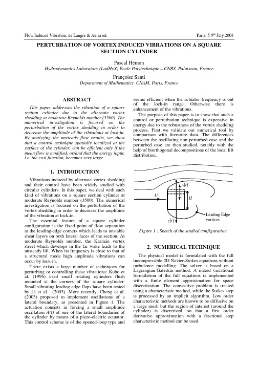
Flow Induced Vibration, de Langre & Axisa ed. Paris, 5-9th July 2004 PERTURBATION OF VORTEX INDUCED VIBRATIONS ON A SQUARESECTION CYLINDERPascal HémonHydrodynamics Laboratory (LadHyX) Ecole Polytechnique – CNRS, Palaiseau, FranceFrançoise SantiDepartment of Mathematics, CNAM, Paris, FranceABSTRACTThis paper addresses the vibration of a square section cylinder due to the alternate vortex shedding at moderate Reynolds number (3500). The numerical investigation is focused on the perturbation of the vortex shedding in order to decrease the amplitude of the vibrations at lock-in. By analyzing the unsteady flow results, we show that a control technique spatially localized at the surface of the cylinder, can be efficient only if the mean flow is modified, or/and that the energy input, i.e. the cost function, becomes very large.1.INTRODUCTION Vibrations induced by alternate vortex shedding and their control have been widely studied with circular cylinders. In this paper, we deal with such kind of vibrations on a square section cylinder at moderate Reynolds number (3500). The numerical investigation is focused on the perturbation of the vortex shedding in order to decrease the amplitude of the vibration at lock-in.The essential feature of a square cylinder configuration is the fixed point of flow separation at the leading-edge corners which leads to unstable shear layers on both lateral faces of the section. At moderate Reynolds number, the Kármán vortex street which develops in the far wake leads to the unsteady lift. When its frequency is close to that of a structural mode high amplitude vibrations can occur by lock-in.There exists a large number of techniques for perturbing or controlling these vibrations: Kubo et al. (1996) used small rotating cylinders flush mounted at the corners of the square cylinder. Small vibrating leading edge flaps have been tested by Li et al. (2003). More recently, Cheng et al. (2003) proposed to implement oscillations of a lateral boundary, as presented in Figure 1. The actuation consists in forcing a small amplitude oscillation A(t)of one of the lateral boundaries of the cylinder by means of a piezo-electric actuator. This control scheme is of the opened-loop type and seems efficient when the actuator frequency is out of the lock-in range. Otherwise there is enhancement of the vibrations.The purpose of this paper is to show that such a control or perturbation technique is expensive in energy due to the robustness of the vortex shedding process. First we validate our numerical tool by comparison with literature data. The differences between the oscillating non perturbed case and the perturbed case are then studied, notably with the help of biorthogonal decompositions of the local lift distribution.Figure 1 : Sketch of the studied configuration.2.NUMERICAL TECHNIQUEThe physical model is formulated with the full incompressible 2D Navier-Stokes equations without turbulence modelling. The solver is based on a Lagrangian-Galerkin method. A mixed variational formulation of the full equations is implemented with a finite element approximation for space discretization. The convective problem is treated using a characteristic method, while the Stokes step is processed by an implicit algorithm. Low order characteristic methods are known to be diffusive on a large mesh but the region of interest (around the cylinder) is discretized, so that a first order derivative approximation with a fractional step characteristic method can be used.For the cylinder motion, the numerical simulations consider forced oscillations y(t) normal to the flow as in Figure 1. Since the movement is that of a rigid body, the vibrations of the structure are simulated by applying the movement on the external boundary conditions. The computations are then performed in the reference frame of the body, and the grid acceleration term is taken into account in the equations.The effect of the actuator acting as a perturbation of small amplitude is simulated with an unsteady boundary condition. The normal velocity )(t A is then prescribed at the upper surface of the cylinder (see Figure 1).3. STATIC CASEIn a first step, the static case, without motion and without perturbation is simulated in order to validate the numerical technique. The Reynolds number based on the side H of the cylinder is 3500. The computed aerodynamic coefficients of the cylinder are presented in Table 1. The mean drag, its root-mean-square (RMS), the RMS value of the lift, the Strouhal number and the base pressure coefficient are globally in agreement with literature data (Bearman & Obasaju, 1982 ; Davis & Moore 1982 ; Norberg, 1993 ; Verstappen, 2002 ; Yi & Okajima 1996). The RMS amplitude of the lift is more or less twice that observed on a circular cylinder (Bearman & Obasaju, 1982), due to the large lateral walls of the square shape which are submitted to the stalled flow.150200250Time−2021.52.02.5 C xC zFigure 2 : Time history of drag and lift forces,static case A sample of drag and lift coefficients versus dimensionless time is given Figure 2, after a stationary state has been reached. We can observe the standard oscillating behaviour, with the drag fluctuation at a frequency twice that of the liftforce, which defines the Strouhal number of the alternate vortex shedding. The drag evolution, showing a subharmonic is typical of the moderate Reynolds number range (Davis & Moore, 1982).4. OSCILLATING CASES4.1 Non perturbed caseThe cylinder is now put into motion at the frequency St = 0.139 of the vortex shedding in order to simulate the oscillating corresponding case, as in the experiments presented by Cheng et al. (2003). The imposed motion is sinusoidal: ()()ϕπ+=t St z t z 2sin 0.(1)The motion amplitude z 0 is set to 8% of the dimension H of the section. Note that the results presented hereafter are for a stationary state in which the transient period between static case and oscillating one has been removed. Hence, the phase angle ϕ in equation (1) is not significant.Time histories of the force coefficients are given in Figure 3, together with the cylinder section velocity z .300350400Time−2021.52.02.5−0.20.00.2 C xC zzFigure 3 : Time history of drag and lift force, nonperturbed oscillating case. The resulting lift force is delayed of 30° with the cylinder displacement, which is in the range of the drastic change observed in the experimental results of Bearman and Obasaju (1982). Moreover, they noticed that the unsteady lift is increased by thecylinder motion, which is found also by the present computation, as presented in Table 2. The mean drag decrease has also been found by Yi and Okajima (1996).xC x RMS 0.16C z RMS 1.40St 0.139Cp base -1.51Table 1 : Computed aerodynamic coefficients of thestatic case(a) (b)C x mean 1.92 2.14C x RMS 0.20 0.24C z RMS 1.44 1.46Table 2 : Computed aerodynamic coefficients(a) non perturbed oscillating case ; (b) perturbed4.2Perturbed oscillating caseIn this section, we now simulate the perturbed oscillating case using the parameters values presented by Cheng et al. (2003) in their experiments. The cylinder displacement remains similar to equation (1) with an amplitudez decreased to 2% of H.The displacement generated by the actuator is ()()ϕπ+=tStAtA c2sin, (2) in which the control Strouhal number St c is 0.1 andthe amplitudeA is 2.8% of H. Once again, the phase angle is not significant at stationary state. Note also that the cylinder displacement is forced at another frequency. This will generate a very low frequency component (i.e. St-St c) corresponding to the interaction between cylinder displacement and the actuator.The resulting force coefficients are given in Table 2. The mean drag recovers more or less the value of the static cylinder, due to the vortex location closer to the base of the cylinder, thus decreasing the base pressure coefficient.But the drag and lift, in terms of RMS value are not decreased as it is expected with the perturbation scheme and a deeper analysis of the results is necessary. Time histories are presented in Figure 4 with the cylinder velocity z and the perturbation velocity A(dotted line). It is interesting to notice that with the parameters chosen by Cheng et al. (2003), the velocity amplitude of the cylinder motion and that of the perturbation are of same order.It is clear in Figure 4 that the drag is really perturbed, showing disorganized oscillations. Thus the RMS value is not a pertinent indicator because the corresponding spectrum shows a number of frequencies in the signal. However, this is not the case for the unsteady lift which shows indeed a quasi-sinusoidal evolution, weakly modulated at low frequency. The corresponding RMS value weakly perturbed is therefore pertinent.380430480Time−221.52.02.5−0.020.000.02Az,C xC zFigure 4 : Time history of drag and lift forces,perturbed oscillating case.It must also be mentioned that, in another case not presented here due to limited length, we have simulated the enhancement of vortex shedding and of the lift by setting the perturbation frequency as the same value as the natural shedding (i.e. St=St c). Results were in agreement with the similar experimental tests of Cheng et al. (2003).PARISON AND ANALYSIS 5.1Flow morphologyFrom the previous results, it seems that the perturbation scheme is not efficient enough to decrease the vortex shedding effect on the lift.In Figure 5 the vorticity distribution, superimposed with contour of iso-pressure, are plotted at the instant of maximum lift, for the non perturbed (5a) and perturbed (5b) cases. We observe that the actuator injects locally an additional circulation which remains confined in the shear layer, as it can be seen on the uppersurface of the cylinder section (Figure 5 b). But the main wake vortices are not really influenced by the perturbation, which explain the results concerning the lift force.Thus to overcome natural vortex shedding, the amplitude of the perturbation must be much larger than the one used here. This point will be discussed later.(a)(b)Figure 5 : Comparison of vorticity distributions, (a) non perturbed oscillating case; (b) perturbed We perform now a deeper comparison of the two cases via the spatio-temporal analysis of the wall pressure coefficients. We use then the biorthogonal decomposition of the local lift force in the way that we have proposed recently (2003). This technique is useful in analysing complex signals by decomposing them into space functions (called topos) and time functions (called chronos) which are orthogonal between them and classified by order of importance.For the oscillating case, the first 6 topos are shown Figure 6, with the wind blowing from left to right. The topos 1 is representative of the average value and is not relevant in the discussion. The corresponding chronos (with the first one removed) are presented Figure 7.It is found that the main component of the lift (more than 99%) is given by the second chronos and topos. On the latter, it is interesting to note that the downstream part of the two side boundaries have a low contribution in the global lift.123456Figure 6 : Topos, oscillating case300350400Time−0.050.000.05−0.050.000.05−0.050.000.05−0.050.000.05−0.050.000.0523456Figure 7 : Chronos, oscillating caseFor the perturbed oscillating case, the topos and the chronos are presented similarly in Figure 8 and 9. As for the non perturbed case, the second spatio-temporal structure (topos + chronos) is sufficient to recompose the total lift at a level larger than 99%.123456Figure 8 : Topos, perturbed oscillating case380430480Time−0.050.000.05−0.050.000.05−0.050.000.05−0.050.000.05−0.050.000.05234 5 6Figure 9 : Chronos, perturbed oscillating caseIt is seen that the effects of the perturbation are located on the topos 3 and 4 because these structures do not appear in the decomposition of the non perturbed case. The topos 5 and 6 of theperturbed case indeed remain similar to the topos 4 and 5, respectively (eventually up to an arbitrary sign), of the non perturbed case.Therefore the perturbation is shown to deeply modify the topos 3 of the non perturbed case, transforming this structure into the topos 3 and 4. Note that the non perturbed topos 3 has a symmetrical shape on the upper boundary compared to the lower boundary, leading to a zero lift force. For the perturbed case, this symmetry remains but it is decomposed into two topos (3 and 4). But these structures have a contribution in terms of global force which is representative of the drag (and the pitching moment) as it can be seen on the corresponding chronos that are similar to the drag time history.The spatio-temporal analysis confirms then that the lift produced by the alternate vortex shedding is globally not perturbed by the actuator. The perturbation, localized inside the shear layer, is not able to disorganize the instability which is caused by the mean flow characteristics around the cylinder section. 5.2 ActuationIn fact this control scheme is very different of those of Kubo et al. (1996) or Li et al. (2003) for which the actuators are mounted at the leading edge corners of the square section. These corners are the separation points where the two shear layers are generated, thus where a perturbation will have a maximum efficiency.The mean flow characteristics can be modified by these schemes, which can lead for instance to the generation of a steady lift, indicating a global change in the stall regions on the lateral faces of the section.It is therefore interesting in the present case to consider the effects of the amplitude A 0 of the perturbation. Without oscillation of the cylinder, the main results are given in Table 3.A 0 0 2.8 % 10 % x C x RMS 0.15 0.21 0.22 C z RMS 1.40 1.38 1.18 Table 3 : Computed aerodynamic coefficients without oscillation versus perturbation amplitudeIt is seen that the small amplitude of 2.8 % is not able to modify significantly the unsteady lift value, and the mean drag remains unchanged.To observe a decrease of the unsteady lift, the actuator amplitude has to be increased up to 10 %. In this case, the perturbation leads to a mean drag decrease of about 10 %, which means that the wakemorphology has also been modified. But the energy associated to the actuator, roughly proportional to the square of the perturbation amplitude, becomes then of the same order as that of the oscillations.6.CONCLUSIONA numerical study of perturbed oscillations of a square section cylinder, due to alternate vortex shedding, has been presented. With the help of biorthogonal decomposition of the unsteady lift distribution, a spatio-temporal analysis was performed. We have shown that the perturbation scheme, similar to the experiments of Cheng et al. (2003), is efficient in perturbing the base flow only when the actuator amplitude is high.Further work is to use another approach in understanding the sensitivity of the flow to perturbation. The idea is to use the results of the stability theory, based on the wake velocity profile as the base flow.7.REFERENCES BEARMAN, P.W. & OBASAJU, E.D., 1982 An experimental study of pressure fluctuations on fixed and oscillating square-section cylinders. Journal of Fluid Mechanics119: 297-321.CHENG, L., ZHOU, Y. & ZHANG, M.M., 2003 Perturbed interaction between vortex shedding and induced vibration. Journal of Fluids and Structures 17: 887-901.DAVIS, R.W. & MOORE, E.F., 1982 A numerical study of vortex shedding from rectangles. Journal of Fluid Mechanics, 116: 475-506.HEMON, P. & SANTI, F., 2003 Applications of biorthogonal decompositions in fluid-structure interactions. Journal of Fluids and Structures17: 1123-1143.KUBO, Y., MODI, V.J., KOTSUBO, C., HAYASHIDA, K. & KATO, K., 1996. Suppression of wind-induced vibrations of tall structures through moving surface boundary-layer control. Journal of Wind Engineering and Industrial Aerodynamics61: 181-194.LI, Y.F., FLAY, R.G.J. & RICHARDS, P.J., 2003 Cross-wind excitation of a 2D square prism with vibrating leading edge flaps. Journal of Wind Engineering and Industrial Aerodynamics91: 185-197. LUO, S.C., YAZDANI, Md.G., CHEW, Y.T. & LEE T.S., 1994 Effects of incidence and afterbody shape on flow past bluff cylinders. Journal of Wind Engineering and Industrial Aerodynamics53: 375-399.NORBERG, C. 1993. Flow around rectangular cylinders: pressure forces and wake frequencies. Journal of Wind Engineering and Industrial Aerodynamics49: 187-196.VERSTAPPEN R. 2002. On computing a turbulent square cylinder wake. Conference on Bluff Body Wakes and Vortex-Induced Vibrations (BBVIV3), Port Douglas, Australia, 17-20 December.YI D. & OKAJIMA A. 1996 Aerodynamic forces acting on an oscillating rectangular cylinder and the aeroelastic instabilities at moderate Reynolds number (experiments). JSME International Journal, series B, 39(2): 343-353.。

结构的连续倒塌:规范介绍和比较梁益陆新征缪志伟叶列平(清华大学土木工程系,北京,100084)摘要: 目前,结构的连续倒塌已成为严重威胁公共安全的重要问题,因而日益受到关注。
国外自1968年英国Ronan Point公寓倒塌事件发生以来,已经对连续倒塌问题进行了三十余年的研究,并编制了相关设计规范。
而我国规范目前尚未规定详细抗连续倒塌设计方法。
因此,本文对国外主要的抗连续倒塌设计规范(如美国ACI 318,GSA 2003,DoD 2005、欧洲EuroCode 1、英国BS8100等)中相应的抗连续倒塌设计条文进行了总结和比较,并在此基础上提出了一些结构抗连续倒塌的设计概念和几种主要的设计方法,以及我国在这方面需要解决的问题,可供我国编制相关规范参考。
关键词: 连续倒塌规范设计方法Progressive Collapse of Structures: Introduction and Comparison ofStandardsLiang Yi Lu Xin-zheng Miao Zhi-wei Ye Lie-ping(Department of Civil Engineering, Tsinghua University, Beijing, 100084)Abstract: Currently, the progressive collapse of the structures has become a serious threat to the public safety. Since the collapse of the Ronan Point Tower in United Kingdom in 1968, north America and Europe have conducted more than 30 years of research to this issue and developed relevant design codes and design guides. However, codes in China have not yet provided details on the resistance of progressive collapse. In this paper, the corresponding design specifications for the progressive collapse prevention in the main foreign design codes (e.g.,ACI 318-02,GSA 2003,DoD 2005、EuroCode1、BS8100) are summarized and compared. Then, the major design methods to prevent progressive collapse are proposed and suggestions are given for the Chinese codes.Key words:progressive collapse codes design method1 前言结构的连续倒塌是由于意外荷载造成结构的局部破坏,并引发连锁反应导致破坏向结构的其它部分扩散,最终使结构主体丧失承载力,造成结构的大范围坍塌。
BMW Group Standard GS97034--82008--02 Deskriptoren:Beschichtet,Innenraum,Material,Oberfläche,Schreib-neigung,unbeschichtetDescriptors:Coated,interior,material,surface,scratch inclination,uncoatedOberflächenprüfung von Kfz-Innenraummaterialien Bestimmung der SchreibneigungSurface test of motor vehicle interior materialsDetermination of the scratch inclinationAusdrucke unterliegen nicht demÄnderungsdienst.Print-outs are not subject to the change service.Fortsetzung Seite2bis4Continued on pages2to4BMW AG Normung:80788MünchenE BMW AG interleaf-doc Alle Rechte vorbehalten/All rights reserved Bearbeiter/Editor:Norbert MaierSeite/Page2GS97034--8:2008--02In case of dispute the German wording shall be valid. Vorwort ForewordDieser Group Standard wurde mit den verantwortlichen Bereichen des BMW Konzerns abgestimmt.This Group Standard has been coordinated with the responsible departments of the BMW Group.ANMERKUNG Der Group Stand ersetzt die“Glanzprü-fung“und die Prüfung mit der Stahlscheibe quer zur Prüf-richtung in der PR307.4.NOTE The Group Standard replaces the“Luster test”and the test with the steel disk laterally to testing direction in PR307.4.1Anwendungsbereich und Zweck1Scope and purposeDie im KFZ-Innenraum befindlichen Oberflächenmaterialien kommen mit unterschiedlichen Gegenständen,wie z.B.Fin-gerring,Schlüssel oder andere scharfkantige und harte Ge-genstände,in Berührung Interior surface materials have contact with various objects, like finger ring,key or other sharp-edged and hard objects.Dieser Group Standard beschreibt die Bestimmung der Schreibneigung,er gilt für beschichtete und unbeschichtete Oberflächenmaterialien,vorzugsweise für harte Oberflächen.This Group Standard describes the determination of the scratch inclination and applies to coated and uncoated surface materials,preferably for hard surfaces.Dieses Prüfverfahren dient zur Bestimmung der Wider-standsfähigkeit von Oberflächenmaterialien gegenüber Schreibspur verursachende Gegenstände.This test procedure serves for the determination of the resistance of surface materials against objects that may cause scratches.Zweck dieses Group Standards ist die Festlegung einer ein-heitlichen Prüfung zur Eignung des Materials.The purpose of this Group Standard is to determine a standardized test for evaluation of the suitability of the material.Die Festlegung der zu prüfenden Teile ist mit den betroffenen Fachstellen abzustimmen.The range of the parts to be tested must be coordinated with the involved specialist departments.Bei Aluminiumoberflächen gelten abweichende Bedingun-gen,die in Abschnitt7beschrieben sind.For aluminium surfaces the deviating conditions described in chapter7apply.2Normative Verweisungen2Normative referencesDiese Norm enthält Festlegungen aus anderen Publikatio-nen.Diese normativen Verweisungen sind an den jeweiligen Stellen im Text zitiert und die Publikationen sind nachstehend aufgeführt.Es gilt die letzte Ausgabe der in Bezug genomme-nen Publikation.This Standard incorporates provisions from other publications.These normative references are cited at the appropriate places in the text and the publications are listed hereafter.The respective latest edition of the publication is applicable.DIN50014Klimate und ihre technische Anwen-dung;Normalklimate DIN50014Climates and their technicalapplication;Standard atmospheresAA--N068Universalkratzprüfstand(UKP)AA--N068Universal scratch tester 3Prüfverfahren3Test procedureDie Proben werden bei Normklima DIN50014(23°C und 50%relative Feuchte)geprüft.The specimens are tested under standard climate DIN50014 (23°C and50%relative humidity).Der vorgegebene Prüfkörper wird relativ zur Prüffläche mit konstanter Prüfkraft und Geschwindigkeit bewegt.The specified test body is moved relative to the surface to be tested with a constant test force and at constant speed.Die Prüfkraft wird in Etappen gesteigert(1N,3N,5N,8N, 10N,12N,15N,20N).Hierbei wird die zu prüfende Oberflä-che für jede Prüfkraft einmalig belastet.The test force is raised incrementally(1N,3N,5N,8N,10N, 12N,15N,20N).For each test force the surface to be tested is once subjected to the load.Bevorzugt sind die Prüfungen an ebenen Proben durchzufüh-ren.Prefereably,the tests are to be performed on planar specimens.Der Prüfweg soll>60mm betragen.The test path shall be>60mm.Für die Durchführung der Prüfung ist grundsätzlich jeder Prüf-aufbau geeignet,welcher eine Prüfung im Rahmen der aufge-führten Parameter ermöglicht.As regards the implementation of the test,generally any test setup is suitable that allows for testing within the frame of the specified parameters.Ein Beispiel eines geeigneten Prüfaufbaus ist unter Abschnitt6genannt.Chapter6shows a example of a suitable test setup.Seite/Page3GS97034--8:2008--023.1Geräteparameter 3.1Device parametersPrüfgeschwindigkeit:(40±5)mm/s Test speed:(40±5)mm/sPrüfkraft:1N,3N,5N,8N,10N,12N,15N,20N Test force:1N,3N,5N,8N,10N,12N,15N,20NToleranz:≤20%Tolerance:≤20%3.2Prüfkörper 3.2Test specimen Bezeichnung:Erichsenspitze∅3mm Designation:“Erichsen”tip∅3mm Werkstoff:Stahl gehärtet Material:Steel hardened Abmessung:Durchmesser Spitze3mm Dimension:Diameter of the tip3mmBild1Prüfkörper Figure1Test specimenDie Spitze ist unter30facher Vergrößerung zu untersuchen, ob die harte Spitze glatt,halbkugelförmig und frei von Verun-reinigungen ist.Gegebenenfalls ist ein Austausch der Spitze oder eine Reinigung erforderlich.The tip must be checked under30-fold magnification.It must be ensured that the hard tip is smooth,half-spherical and free from soiling.The tip must be replaced or cleaned if necessary.Die Bezugsquelle kann bei den Fachabteilungen“Labortech-nik Standort München/Werkstofftechnik Nichtmetall”erfragt werden.The source can be requested from the specialist departments “Laboratory Technology Munich/Materials Technology Non Metal”.3.3Probe 3.3Sample Probengeometrie:Sample geometry:Probenlänge:>100mm Sample length:>100mm Probenbreite:>140mm Sample width:>140mmUm die einzelnen Abstufungen besser bewerten zu können, ist nach jeder Kratzprüfung bei Lastwechsel der Zeilenab-stand um5mm zu verschieben(siehe Bild2).For a better evaluation of the individual gradings,after each scrach test the line spacing must be shifted by5mm at stress reversal(see Figure2).Bild2Beispiel einer geprüften Platte Figure2Example of a tested plateSeite/Page4GS97034--8:2008--023.4Allgemeines 3.4GeneralIn Schiedsfällen sind die Prüfungen an einem Gerät im Hause BMW durchzuführen.In case of arbitration the tests must be performed on a BMW-device.Vor der Prüfung sind die Proben mit einem trockenen fussel-freien Tuch zu reinigen.Prior to testing the specimens must be cleaned with a fuzz-free cloth.4Auswertung4EvaluationDie Auswertung und die zulässigeÄnderung wird in den für das Bauteil maßgeblichen Technischen Lieferbedingungen oder Group Standard festgelegt.The evaluation and the permitted change is defined in the Technical Delivery Specification or Group Standard that is authoritative for the component.5Angaben im Prüfbericht5Specifications in the test reportIm Prüfbericht sind unter Hinweis auf diese Norm die Art,die Bezeichnung und der Aufbau des geprüften Materials und der Prüfaufbau anzugeben.The test report shall indicate the type,designation and structure of the tested material and the test setup,including reference to this standard.Von dieser Norm abweichende Prüfparameter sind im Prüfbe-richt zu dokumentieren.Test parameters deviating from this standard must be documented in the test report.6Beispiel geeigneter Prüfaufbau6Example of suitable test setup 6.1Universalkratzprüfstand 6.1Universal scratch test rigDer Universalkratzprüfstand ist eine Eigenentwicklung der Fa.BMW.Nähere Informationen zum Prüfstand können bei der Fachstelle“Labortechnik Standort München/Werkstoff-technik Nichtmetall”oder bei der Fa.Erichsen eingeholt wer-den.The universal scratch test rig is an internal BMW development.For further information regarding the test rig contact specialist department“Laboratory Technology Munich/Materials Technology Non Metal”or company Erichsen.Die Prüfung ist in der AA--N068beschrieben.The test is described in AA--N068.6.2Ritzhärteprüfgerät 6.2Scratch hardness testerRitzhärteprüfgerät430P der Fa.Erichsen.Nähere Informatio-nen zum Prüfgerät können bei der Fachstelle“Kunststoffent-wicklung,Verfahrenstechnik/Verbundwerkstoffe,Techni-kum”eingeholt werden.Scratch hardness tester430P from company Erichsen.For further information regarding the tester contact specialist department“Plastics Development,Process Technologies/ Composite Materials,Advanced Technology Center.”7Abweichende Bedingungen bei Aluminium-oberflächen7Deviating conditions at aluminium surfacesDie Prüfkraft wird in Etappen gesteigert(1N,2N,3N,4N, 5N,8N,10N,12N,15N,20N).Hierbei wird die zu prüfende Oberfläche für jede Prüfkraft jeweils zweimal in orthogonal zu-einander liegenden Richtungen belastet.The test force is raised incrementally(1N,2N,3N,4N,5N, 8N,10N,12N,15N,20N).For each test force the surface to be tested is two times subjected to the load in directions arranged orthogonally to each other.Die Auswertung der geprüften Aluminiumplatten oder Bau-teile erfolgt durch die Fachabteilung“Strukturwerkstoffe”,die eine schriftliche Empfehlung erstellt und an die Fachabteilung “Design-Technik-Konvergenz Innenraum,Wertigkeit/Mate-rial und Verarbeitung”übermittelt.The evaluation of the tested aluminium plates or components is performed by the specialist department“Structural Materials”,preparing a written recommendation and submitting it to the specialist department“Styling-Design-Convergence Interior and Value perceived/Material and Processing”.。
<<Project Name>>Project StructureCustomer NameDirections for using template:Read the Guidance (Arial blue font in brackets) to understand the information that should be placed in each section of this template. Then delete the Guidance and replace the placeholder within <<Begin text here>> with your response. There may be additional Guidance in the Appendix of some documents, which should also be deleted once it has been used.Some templates have four levels of headings. They are not indented, but can be differentiated by font type and size:•Heading 1 – Arial Bold 16 font•Heading 2 – Arial Bold Italic 14 font•Heading 3 – Arial Bold 13 font•Heading 3 – Arial Bold Italic 12 fontYou may elect to indent sections for readability.AuthorAuthor PositionDateVersion: 1.02002 Microsoft Corporation. All rights reserved.The information contained in this document represents the current view of Microsoft Corporation on the issues discussed as of the date of publication. Because Microsoft must respond to changing market conditions, it should not be interpreted to be a commitment on the part of Microsoft, and Microsoft cannot guarantee the accuracy of any information presented after the date of publication.This document is for informational purposes only. MICROSOFT MAKES NO WARRANTIES, EXPRESS OR IMPLIED, IN THIS DOCUMENT.Microsoft and Visual Basic are either registered trademarks or trademarks of Microsoft in the United States and/or other countries.Revision & Sign-off SheetChange RecordDate Author Version Change ReferenceReviewersName Version Approved Position Date DistributionName PositionDocument PropertiesItem DetailsDocument Title Project StructureAuthorCreation DateLast UpdatedTable of ContentsProject Approaches (6)Project Goals, Objectives, Assumptions, and Constraints (6)Project Scope (6)Project Trade-off Matrix (6)Master Project Approach (7)Milestone Approach (8)Project Estimates (9)Schedule Summary (9)Roles and Responsibilities (9)Knowledge, Skills, and Abilities (10)Team Structure (10)Project Protocols (10)Risk and Issue Management Approach (10)Configuration Management Approach (11)Change Management Approach (11)Release Management Approach (12)Project Quality Assurance Approach (12)Project Communication Approach (12)Team Environment Approach (13)Risk and Issue Assessment (14)Project Glossary (14)[Introduction to the TemplateDescription: The Project Structure document defines the approach the team will take in organizing and managing the project. It is the strategic representation of initial decisions made regarding goals, work scope, team requirements, team processes, and risk.Justification: The Project Structure baseline is created during the envisioning phase and is utilized and revised throughout the remaining phases, serving as an essential reference for the project team on how they will work together successfully.Team Role Primary: The Program Management role is responsible for facilitating the creation of the document with input from all other core team members.]Project Approaches[The Project Approaches section defines how the team will manage and support the project. These sub-sections provide descriptions of project scope, approaches, and project processes.]Project Goals, Objectives, Assumptions, and Constraints [Description: The Project Goals, Objectives, Assumptions, and Constraints section describe the project environment:•Goals (the project’s final purpose or aim)•Objectives (the goals broken into measurable components)•Assumptions (factors considered true, real, or certain, and that await validation)•Constraints (a non-functional requirement that will limit the project team’s options).Project Goals and Objectives are initially derived from the business goals and objectives that are developed during the opportunity phase and confirmed during the envisioning phase. Assumptions and Constraints may be derived from strategic Microsoft services (Rapid Portfolio Alignment, Rapid Economic Justification) and research regarding the customer’s environment.Justification: Project Goals and Objectives articulate the c ustomer’s and team’s expectations of the project and can be converted into performance measurements. Project Assumptions attempt to create explicit information from implicit issues and to point out where factual data is unavailable. Project Constraints place limits on the creation of boundaries and decision-making.]<<Begin text here>>Project Scope[Description: The Project Scope section defines the tasks, deliverables, resources, and schedule necessary to deliver the customer’s solution. The tasks are ex pressed in the Master Project Approach, the Milestone Approach, the Project Estimates, and the Project Schedule. These multiple views allow the customer and project team to look at the project from different perspectives and to analyze how the work is organized.Justification: The tasks, deliverables, resources, and schedule exist at a high level of detail. These Project Scope statements provide the context for more detailed planning during follow-on project phases.]<<Begin text here>>Project Trade-off Matrix[Description: The Project Trade-off Matrix is a table that represents the customer’s preferences in setting priorities among schedule, resources and features.Note: when using the graphic, move the check marks to the appropriateboxes and fill in the _____(blanks) within the sentence.Justification : The Trade-off Matrix sets the default standard of priorities and provides guidance for making trade-offs throughout the project. These trade-offs should be established up front and then reassessed throu ghout the project’s life.]Given fixed ___________, we will choose a ___________, and adjust_________ as necessary.Master Project Approach[Description : The Master Project Approach is the roll-up of all the project teams ’ approaches. This includes an overall statement of strategy for the project and individual strategy statements for each team. A strategy statement describes a general approach to accomplish work without associated metrics.The Master Project Approach also describes how the various project teams will collaborate to build and deploy the customer solution. This creates an awareness of the dependencies among the teams.This section should also include a description of the high-level work tasks to be undertaken by each team. The work can be described in part by identifying what its result or deliverable will be. This description can also include things such as tools, methodologies, best practices, sequences of events, etc.Justification : The Master Project Approach ensures that each team understands how it will contribute to the project’s overall success. In addition, it communicates to FeaturesS s o u r c se R e c h e d u l e Chosen Fixed Adjustable ScheduleFeature SetResourcesthe customer that Microsoft and its partners are working from a well-developed strategy. The Master Project Approach evolves into the Master Project Plan during the planning phase.]The sections below describe the project team’s approach to building the project work packages.[Note: The sections identified below are suggested categories. Modify thesecategories to fit your project. ]Development Approach<<Begin text here>>Test Approach<<Begin text here>>Training Approach<<Begin text here>>User Support Approach<<Begin text here>>Communication Approach<<Begin text here>>Deployment Approach<<Begin text here>>Operations Approach<<Begin text here>>Milestone Approach[Description: The Milestone Approach identifies the significant events in the project’s lifespan. During envisioning, these are usually expressed as External Milestones that identify visible accomplishments of high-level deliverables and illustrate the project’s schedule targets. At the highest level, External Milestones can be associated with the completion of a specific project phase.The Milestone Approach identifies the basis for establishing milestones. Depending on the nature of the project, Milestones can be finance-based, progress-based,product-based, and so on. The Milestone Approach defines this basis and identifies the milestone events that will be tracked.Justification: Describing Milestones early in the project establishes high-level time targets the customer can confirm and the team must anticipate during its planning activities. It also identifies the checkpoints where Milestone Reviews will occur to assess the project’s quality a nd its results.]<<Begin text here>>Project Estimates[Description: The Project Estimates section contains an estimate of the resources and costs required for the project teams to accomplish their work. Resources include people, equipment, facilities, and material. Costs are calculated by applying rates to each type of resource requirement. This section should contain the following information, broken out by each functional team:• A list of resource types•The amount of the resource required•The rate applied to each resource•The cost of each resource•Total cost of resources for each functional teamThis section should also contain the cost for all resources summed together. Justification: Project Estimates provide information for calculating the budget estimate. They also enable the project manager and team leads to identify the specific resources needed to perform the work.]<<Begin text here>>Schedule Summary[Description: The Schedule Summary section identifies and compiles the collective work tasks and their calendar dates into a complete project schedule that identifies its beginning and end dates. Each major Project Milestone is identified and assigned a targeted completion date. The schedule is a consolidated schedule — it includes the work and dates of all project teams.The scheduling process is iterative. During the envisioning phase, the project’s Major Milestones anchor the schedule. During the planning phase, the schedule will become more granular as the work tasks are broken down.Justification: The Schedule provides the basis for the customer to verify timelines and for the project team to produce a constrained master plan from which it can validate proposed budgets, resources, and timescales.]<<Begin text here>>Roles and Responsibilities[Description: The Roles and Responsibilities section defines how people will be organized in the project. The assurance of quality resources and structure begins with creating people “requirements” and follows with organizing those people intoteams and allocating responsibility. Clear statements of skill requirements and roles and responsibilities enable the project manager to select the right people and communicate to them how they will contribute to the project’s success.] Knowledge, Skills, and Abilities[Description: The Knowledge, Skills, and Abilities section specifies the requirements for project participants. This is expressed by defining the knowledge, skills, and abilities needed to conduct the project. These requirements should include technical, managerial, and support capabilities. This information is organized into functional teams and responsibilities. At the highest level, the KSA can be based on the standard MSF roles. Each functional team, or MSF role, is listed, and the team’s knowledge, skills, and abilities requirements are defined alongside.Justification: Knowledge, Skills, and Abilities information will facilitate the careful selection of specific project participants and provide the basis for creating the core team structure.]<<Begin text here>>Team Structure[Description: The Team Structure section defines the project’s organizational entities (project manager, sponsor(s), steering committee, team leads, etc.), illustrates their relationships to one another, and defines levels of responsibility and reporting structure. When complete, the team structure assigns names to each organizational entity and explicitly calls out the individual team (or team members) tasked with executing, reviewing, and approving the project’s work. This assignment is spread across all entities participating in the project: Microsoft, Partners, and Customer. Justification: The documentation of the project’s organizational structure ensures that all project participants understand their roles in making the project a success, clarifies lines of reporting and decision-making, and provides key stakeholders an opportunity to ensure that the project’s organizational structure (project form) will facilitate the work (project function).]<<Begin text here>>Project Protocols[Description: Project Protocols are the set of project processes that must be standardized to ensure all project participants are performing the processes in the same manner. This standardization creates performance efficiencies and facilitates a common language among the project stakeholders.]Risk and Issue Management Approach[Description: The Risk and Issue Management Approach section describes the processes, methods, and tools to be used to manage the project’s risks and issues. It must be sufficiently detailed to facilitate the risk and issue management process during the envisioning and planning phases. It must also make it possible to categorize issues as product issues or project issues. This section will include the following:•Description of risk and issue management processes, methods, and tools •Schedule/frequency of risk and issue management activities•Roles and responsibilities within the risk and issue management process•Specifications of the risk/issue assessment form and the issues resolution formJustification: The Risk and Issue Management documentation ensures that all project participants understand their responsibilities in identifying and managing risks and issues, and that all project personnel are using the same risk and issue management processes.]<<Begin text here>>Configuration Management Approach[Description: The Configuration Management Approach section defines how all the project’s deliverables (hardware, software, management and technical documents, and work in progress) will be tracked, accounted for, and maintained. Configuration Management includes project documents, the development and test environments, and any impact on the production environment. This section will include the following: •Description of configuration management processes, methods, and tools•Processes to request configuration changes (steps, approval levels)•Roles and responsibilities for configuration management•Version-control standards for documentsJustification: Configuration Management documentation ensures that the project can maintain object and document integrity so that a single version is used at all times.]<<Begin text here>>Change Management Approach[Description: The Change Management Approach section describes how thepr oject’s scope will be maintained through structured procedures for submitting, approving, implementing, and reviewing change requests. The change management process is charged with providing prompt and efficient handling of any request for change. This section should include the following:•Change management processes, methods, and tools•Composition of the Change Advisory Board•Change request form•Roles and responsibilities of change management activities•Reference to the contractual change order from the Customer Contracting Approach sectionJustification: Documenting the Change Management Approach helps the project maintain a timely single perspective of the project’s scope (both project activities and products produced) and ensure that only contracted work is undertaken.]<<Begin text here>>Release Management Approach[Description: The Release Management Approach section describes the processes, methods, and tools that coordinate and manage releases of the solution to the different test and production environments. It describes the processes of coordinating and managing the activities by which all releases to the production IT environment are planned, tested, and implemented.This section includes the transition plan (release to production) and plans for back-out processes. The approach should be compliant with the Microsoft Operations Framework (MOF) Release Management Process.Justification: This information ensures that the project plans for and follows an orderly process of solution test and implementation, thus limiting the impact on the customer’s operational environment and ensuring that environment is operationally ready to receive the release.]<<Begin text here>>Project Quality Assurance Approach[Description: The Project Quality Assurance Approach section defines how the project intends to deliver products that meet the customer’s quality expectations and Microsoft/Partner quality standards. It addresses both the project’s management and the development of the project’s product. This section should include the following: •Quality expectations•Process for assurance (audit, reviews, contractor controls)•Process for control (peer reviews, inspections, tests)•Quality organization (entities, roles, and responsibilities)•Templates for the Product Review, Project Milestone Review, and Customer Approval reports•Training requirementsJustification: A well-developed Product Quality Assurance Approach is key to managing customer confidence and ensuring the development and deployment of a golden solution.]<<Begin text here>>Project Communication Approach[Description: The Project Communication Approach section defines how and what the project will communicate with its stakeholders. This communication occurs within the team and between the team and external entities. The Project Communication Approach identifies the processes, methods, and tools required to ensure timely and appropriate collection, distribution, and management of project information for all project stakeholders. It also describes the tea m’s strategy for communicatinginternally among team members and company personnel, as well as externally with vendors and contractors.This section includes the following:•Project Stakeholders and their communication requirements•Types of communications (progress reports, change management requests, configuration management documentation, releasemanagement documentation, risks and issues, financial reports, projectplans, technical specifications, etc.) and their standard configurations andmedia•Communication type owners•Project organization/distribution lists•Communication infrastructure requirements (tools, internal and external tracking systems, etc.)The progress report is an important document that should be detailed in this section. It describes how to collect and distribute the non-financial metrics and qualitative information that pertain to project progress, team performance, schedule slippage, risks, and issues that impact the project. The progress report should summarize completed work, report on milestones, and highlight new risks.The Project Communication Approach should be organized into two sections: communication within the project and user communication.The user communication section should include the processes, methods, and tools that will explain the solution to the customer and user communities to ensure rapid and trouble-free adoption of the solution. This should identify the key points along the project cycle where the solution will be presented to the users and provide a description of what is presented (user requirements, functional specifications, prototypes, etc.). This section should identify responsibilities for creating and delivering the user communication and identify a process for collecting user feedback for incorporation into technical documents and the solution.Justification: A well-developed Project Communication Approach ensures that information is available to its users in a timely manner to facilitate decision-making. It sets the expectations with the customer and the project teams that information will be distributed in a standardized fashion and on a regular basis.]<<Begin text here>>Team Environment Approach[Description: The Team Environment Approach section defines the approach for creating the project team environment. It defines the physical environment requirements needed to conduct the project and the plan to establish that environment. Environmental elements include at least floor space (offices, meeting rooms, etc.) and equipment (computers, desks, chairs, telephones, etc.). The requirements should also define the location of the environmental elements and their proximity to each other. It also describes tools, systems, and infrastructure needed bythe team, such as version-control software, developer tools and kit, test tools and kit, etc.In addition to requirements, this section should determine infrastructure staging and the roles and responsibilities for environment setup. If necessary, the requirements can be identified by team role (development, logistics, testing, user education, etc.). Justification: The Team Environment Approach ensures that the working environment is readily available in the timeframes set by the project schedule.]<<Begin text here>>Risk and Issue Assessment[Description: The Risk and Issue Assessment section identifies and quantifies all the risks and issues that have become apparent through the envisioning phase. This section should be developed early in the phase and be updated as more information is gathered. At the close of the envisioning phase, this section should contain all risks and issues that exist at that point in time. The section should include the following: •Risk Identification/Statements: a list of project risks and the conditions and consequences of each of the risks•Risk Analysis: the objective assessment of any risk’s significance; the calculation of risk exposure by assessing probability and impact for eachitem on the list of risks•Risk Plan: the actions that will prevent and minimize risks and provide a course of action if risks occur•Risk Priorities: the top “x” risks the project should focus on Justification: Early identification of risk enables the team to begin managing those risks.]<<Begin text here>>Project Glossary[Description: The Project Glossary defines the meaning and usage of the terms, phrases, and acronyms found in the documents used and developed throughout the opportunity, solution development, implementation, and operations management phases of product or solution development.Justification: The Project Glossary helps to ensure good communication and understanding by providing knowledge, understanding, and common usage for terms, phrases, and acronyms.]<<Begin text here>>。
专题09阅读理解“预测下段”题(考情+技法+真题+模拟)解析版养成良好的答题习惯,是决定高考英语成败的决定性因素之一。
做题前,要认真阅读题目要求、题干和选项,并对答案内容作出合理预测;答题时,切忌跟着感觉走,最好按照题目序号来做,不会的或存在疑问的,要做好标记,要善于发现,找到题目的题眼所在,规范答题,书写工整;答题完毕时,要认真检查,查漏补缺,纠正错误。
【近年高考考情】1.(2023·全国乙卷·C篇)31题2.(2011·安徽·高考真题·B篇)63题3.(2010·湖北·高考真题·B篇)58题【实用解题妙招】一、设问方式1. What will be talked about if this passage continues?2. What might be discussed in the following paragraph?3. What would the author probably discuss in the paragraph that follows?二、实用妙招考生在阅读全文基础上,“预测下段”类试题应注意以下两点策略:1. 从最后一段入手。
有时候,作者在最后一段提到一个话题,但是没有充分说明,因此需要在下一段就此问题深入分析、论述或讨论。
所以考生学会依据最后一段甚至最后一句话进行推断也不失为明智选择。
2. 从第一段入手。
实用类说明文往往采用“总分”或者“总分总”结构,即第一段总体概况说明,然后分段阐述。
因此只要考生把握好第一段即主题段内容,顺藤摸瓜,即可推断下段内容应该是主题段中尚未提及的内容。
【高考真题再练】1.(2023全国乙卷C篇)What comes into your mind when you think of British food? Probably fish and chips, or a Sunday dinner of meat and two vegetables. But is British food really so uninteresting? Even though Britain has a reputation for less-than-impressive cuisine, it is producing more top class chefs who appear frequently on our television screens and whose recipe books frequently top the best seller lists.It’s thanks to these TV chefs rather than any advertising campaign that Britons are turning away from meat-and-two-veg and ready-made meals and becoming more adventurous in their cooking habits. It is recently reported that the number of those sticking to a traditional diet is slowly declining and around half of Britain’s consumers would like to change or improve their cooking in some way. There has been a rise in the number of students applying for food courses at UK universities and colleges. It seems that TV programmes have helped change what people think about cooking.According to a new study from market analysts, 1 in 5 Britons say that watching cookery programmes on TV has encouraged them to try different food. Almost one third say they now use a wider variety of ingredients (配料) than they used to, and just under 1 in 4 say they now buy better quality ingredients than before. One in four adults say that TV chefs have made them much more confident about expanding their cookery knowledge and skills, and young people are also getting more interested in cooking. The UK’s obsession (痴迷) with food is reflected through television scheduling. Cookery shows and documentaries about food are broadcast more often than before. With an increasing number of male chefs on TV, it’s no longer “uncool” for boys to like cooking.28. What do people usually think of British food?A. It is simple and plain.B. It is rich in nutrition.C. It lacks authentic tastes.D. It deserves a high reputation.29. Which best describes cookery programme on British TV?A. Authoritative.B. Creative.C. Profitable.D. Influential.30. Which is the percentage of the people using more diverse ingredients now?A. 20%.B. 24%.C. 25%.D. 33%.31. What might the author continue talking about?A. The art of cooking in other countries.B. Male chefs on TV programmes.C. Table manners in the UK.D. Studies of big eaters.【答案】28. A 29. D 30. D 31. B【导语】本篇是一篇说明文,介绍英国人在英国烹饪节目的影响下改变对烹饪的看法,并尝试新的烹饪习惯。
a r X i v :h e p -l a t /9903023v 2 17 M a r 1999February 1,2008The Structure of Projected Center Vortices in Lattice Gauge TheoryR.Bertle a ,M.Faber a ,J.Greensite b,c ,and ˇS.Olejn´ık d a Inst.f¨u r Kernphysik,Technische Universit¨a t Wien,A–1040Vienna,Austria.E-mail:faber@kph.tuwien.ac.at b Physics and Astronomy Dept.,San Francisco State Univ.,San Francisco,CA 94117,USA.E-mail:greensit@ c Theory Group,Lawrence Berkeley National Laboratory,Berkeley,CA 94720,USA.E-mail:greensit@ d Institute of Physics,Slovak Academy of Sciences,SK–84228Bratislava,Slovakia.E-mail:fyziolej@savba.sk AbstractWe investigate the structure of center vortices in maximal center gauge of SU(2)lattice gauge theory at zero and finite temperature.In center projection the vortices (called P-vortices)form connected two dimensional surfaces on the dual four-dimensional lattice.At zero temperature we find,in agreement with the area law behaviour of Wilson loops,that most of the P-vortex plaquettes are parts of a single huge vortex.Small P-vortices,and short-range fluctuations of the large vortex surface,do not contribute to the string tension.All of the huge vortices detected in several thousand field configurations turn out to be unorientable.We determine the Euler characteristic of these surfaces and find that they have a very irregular structure with many handles.At finite temperature P-vortices exist also in the deconfined phase.They form cylindric objects which extend in time direction.After removal of unimportant short range fluctuations they consist only of space-space plaquettes,which is in accordance with the perimeter law behaviour of timelike Wilson loops,and the area law behaviour of spatial Wilson loops in this phase.1IntroductionIt is very well known that the center symmetry is of crucial importance for QCD on the lattice.At the beginning of eighties it was shown that the deconfinement phase transition is connected with the spontaneous breaking of center symmetry[1].In the confined phase field configurations are center symmetric,leading to symmetric distributions of Polyakov loops and to infinite energy of single quarks.In the deconfined phase one center element is favoured by the Polyakov loop distribution,quark charges can be screened by the gluon field.There is now increasing evidence that center symmetry is not only relevant as an order parameter for confinement,but is also the crucial concept in understanding how confine-ment comes about.The idea that center vortices are responsible for confinement was put forward at the end of70’s[2–6],but numerical evidence in favor of this idea is rather recent[7–11].Our principle tool for locating vortices,and investigating their effect on gauge-invariant quantities,is“center projection”in maximal center gauge.Maximal cen-ter gauge is a gauge where all link variables are rotated as close as possible to center elements of the gauge group.Center projection is a mapping from the SU(2)link vari-ables to Z2link variables.“P-vortices”,formed from plaquettes with link product equal to−1(we will call them P-plaquettes),are simply the center vortices of the projected Z2 gauge-field configurations.P-vortices on the projected lattice are thin,surface-like objects,while center vortices in the unprojected configuration should be surface-like objects of somefinite thickness.Our numerical evidence indicates that P-vortices on the projected lattice locate thick center vortices on the unprojected lattice.We alsofind that these thick vortices are physical objects,and that the disordering effect of such vortices is responsible for the entire QCD string tension.Details may be found in ref.[9];a discussion of Casimir scaling in the context of the the center vortex theory is found in ref.[12]and[13].In this article we discuss the structure of P-vortices in center-projectedfield configura-tions.In section two we show that P-vortices tend to form very large vortices(as required if they are the driving mechanism behind quark confinement,see also ref.[14]),and that small-scalefluctuations of the vortex surfaces don’t contribute to the string-tension.Fur-ther,we determine the orientability and the Euler characteristic of these vortices.In section three we investigate the structure of P-vortices atfinite temperature.Wefind,in agreement with Langfeld et al.[15],that in the deconfined phase the vortices are oriented along timelike surfaces in the dual lattice,and are closed by the lattice periodicity;thereby explaining the differing behaviour of timelike and spacelike Wilson loops in this phase.2P-vortices at zero temperature2.1Finding P-vorticesP-vortices are identified byfirstfixing to the direct version of maximal center gauge,which in SU(2)gauge theory maximizes|Tr Uµ(x)|2.(1)x,µThen we map the SU(2)link variables Uµ(x)to Z2elementsZµ(x)=sign Tr[Uµ(x)].(2) The plaquettes with Zµ,ν(x)=Zµ(x)Zν(x+ˆµ)Zµ(x+ˆν)Zν(x)=−1are the“P-plaquettes.”The corresponding dual plaquettes,on the dual lattice,form the closed surfaces(in D=4 dimensions)associated with P-vortices.This can be easily understood by constructing such a P-vortex out of a trivialfield configuration with links Zµ=1.Byflipping a single link to Zµ=−1the six space-time plaquettes attached to this link form an elementary P-vortex.In dual space the corresponding plaquettes form the surface of a cube.Byflipping neighbouring links in real space we get cubes in dual space attached to each other.The dual vortex is the connected surface of these cubes.The distribution of these P-vortices in space-time determines the string tension.The number n of piercings of P-vortices through a Wilson loop determines the value of the projected Wilson loop W cp(I,J)of size A=I×JW cp(I,J)=(−1)n.(3) If p is the probability that a plaquette belongs to a P-vortex,then by assuming the inde-pendence of piercings we get for the expectation value of W cp(I,J)W cp(I,J) =[(1−p)1+p(−1)]A=(1−2p)A=e−σcp A≈e−2pA,(4) where the string tension in center projection isσcp=−ln(1−2p)≈2p.(5) However,for small vortices the independence assumption of piercings is not fulfilled, simply because one piercing is always correlated with another piercing nearby,and therefore small vortices in the average do not contribute to the area law fall-offof large Wilson loops. For this reason,confining vortex configurations will have to be very large,with an extension comparable to the size of the lattice.Fig.1shows the P-vortex plaquettes in a single time-slice of an equilibriumfield configuration on a124-lattice atβ=2.3.The above defined probability p scales nicely with the inverse couplingβ.This was shown in refs.[9,10].However,already from Fig.1of ref.[7]it can be seen that theχ(1,1)Figure1:3-dimensional cut through the dual of a124-lattice atβ=2.3.P-plaquettes are indicated.They form closed two-dimensional surfaces.P-plaquettes which extend in time direction and connect the given3-dimensional space with neighbouring time-slices are indicated by small amputated lines in forward or backward direction.Creutz ratios lie above the asymptotic string tensionσ,and therefore the values of p come out higher than those of f that can be inferred fromσusingf=(1−e−σ)/2.(6) The values of p and f are shown in Fig.2for variousβ-values.Here p is denoted as “unsmoothed”(to stress the difference from values extracted using a smoothing procedure that will be introduced in section2.2),while f is denoted as“stringtension”in Fig.2and was extracted fromχ(3,3)Creutz ratios of the center projectedfield configurations.As shown in ref.[12]the values ofχ(3,3)are in good agreement with the determinations of the string tension by Bali et al.[16].Other data sets shown in Fig.2denoted as“n-smoothing”will be discussed in section2.2.There appears the interesting question about the difference between p depicted in Fig.2under the name“unsmoothed”and f.Introducing various smoothing methods of P-vortices we will show below that this difference originates in short distancefluctuations of P-vortex surfaces.024681012142.2 2.25 2.3 2.35 2.4 2.45 2.5% o f p l a q u e t t e s p i e r c e d b y P -v o r t i c e s beta unsmoothed 0-smoothed 1-smoothed 2-smoothed stringtension Figure 2:Percentage p of P-vortex plaquettes for various β-values and smoothing steps is compared with the fraction f of plaquettes which should be pierced according to the asymptotic string tension σ.2.2Size of P-vorticesOne of the most basic properties of vortices which is connected with the above raised questions is their size.In order to check the size and number of P-vortices we determine neighbouring P-plaquettes,which can be easily done on the dual lattice.In most cases there is no doubt about the neighbouring plaquettes,since most dual links connect only two dual P-plaquettes.But in some cases there appear ambiguities,when dual links are attached to 4or 6dual P-plaquettes.Below we investigate these ambiguities in more detail and discuss possible resolutions.In general P-vortices can be in contact at sites,links and plaquettes.Let’s have a look at these different possibilities.A contact point is of no importance since we define the connectedness via common links.For our case of the Z 2center group a plaquette belonging to two independent vortices leads to a fusion of these vortices.In this context,it is important to understand if the irregular structure of P-vortices depicted in Fig.1is due to such fusion process of simpler vortices.The remaining possibility,a contact of P-vortices at links needs a more detailed discussion.A simple example of such field configurations are two cubes touching like in Fig.3.For such a configuration in dual space it is not clear whether it builds one or two vortices.At the given length scale there is no unique solution for the question of connectedness.Connecting 1with 2,3with 4would result in one vortex,connecting 1with 3,2with 4in two separated vortices.In most cases the situation can be resolved by postponing the decision about the connectedness of these plaquettes until,by following the vortex surface in all other directions,the indicated plaquettes (usually)turn out to be members of the same vortex.There appear some cases where no decision is possible by these means,as inFigure 3:The question of connectedness can not be solved uniquely for this configuration of P-vortices.the simple example of Fig.3.In order to get a lower limit for the size of vortices we decide in such cases to treat the configuration as two separate vortices.It may even occur that vortices touch along closed lines.In these cases parts of the vortex surface can’t be reached following regular connections of plaquettes.These cases are even not so rare,their percentage is shown in Fig.4.The length of the closed line is usually very small and includes in the average 5to 7links.With the above mentioned rules for deciding connectivity of P-vortices in ambiguous cases,we determine the P-vortex sizes.Since most of the plaquettes turn out to belong to the same vortex the most interesting vortex is the largest.The full line in Fig.5shows the percentage of P-vortices belonging to the largest vortex for various values of β,see also [17].For the evaluation at beta=2.2,2.3,2.4and 2.5we used 2000,2000,800and 240field-configurations on 124-,124-,164-and 224-lattices,resp.It is obvious that for T =0and all investigated β-values there is mainly one huge vortex,which contains around 90%of all P-plaquettes.All other vortices are rather small and should not contribute to the string tension according to the above given arguments.Small vortices means strongly correlated010203040506070802.2 2.25 2.3 2.35 2.4 2.45 2.5% o f v o r t i c e s t o u c h i n g a l o n g c l o s e d l i n e s beta unsmoothed 0-smoothed 1-smoothed 2-smoothedFigure 4:Percentage of such P-vortices which touch along closed lines for various types of smoothing.8284868890929496981002.2 2.25 2.3 2.35 2.4 2.45 2.5% o f P -v o r t e x p l a q u e t t e s i n b i g g e s t c l u s t e r beta unsmoothed 0-smoothed 1-smoothed 2-smoothed Figure 5:Percentage of P-plaquettes in the largest vortex for various types of smoothing.piercings resulting in a perimeter contribution to Wilson loops.P-vortices of diameter d lead to correlations for distances larger than d .Only vortices extending over the whole space contribute to an area law at all length scales.We conclude that the string tension is determined by the area of a single huge P-vortex.The fact that P-vortices in the confined phase have an extension comparable to the lattice size is a recent result of Chernodub et al.[14],and our finding is consistent with theirs.The fact that there appears to be only one very large vortex may also be related to results reported by Hart and Teper [18].These authors find that large monopole loops,identified in abelian projection,intersect to form one huge cluster.Since our previous studies [8]indicate that abelian-projection monopoles loops occur mainly on P-vortex surfaces,it seems quite natural that large loops on a single large surface would tend to intersect.2.3Small-scale fluctuations of P-vorticesIn the preceding section we gave an argument why small vortices do not contribute to the string tension.By the same argument,small fluctuations of the vortex surface affect only perimeter law contributions.We will remove these short range fluctuations from P-vortex surfaces and show that the percentage of plaquettes belonging to such smoothed vortices gives directly the string tension σ.In order to follow this idea we introduce several smoothing steps which are depicted in Fig.6.In a first step we identify single isolated P-vortex cubes consisting of six dual P-plaquettes only and remove them.Since we substitute in this step 6plaquettes by 0we call this step 0-smoothing.In the next step called 1-smoothing we identify cubes covered by 5P-vortex plaquettes.Such cubes can be substituted by one complementary6 plaquettes0 plaquettes2 plaquettesFigure 6:Various smoothing steps for vortices.plaquette which closes the cubes.Finally,we substitute cubes with 4plaquettes by the complementary 2plaquettes.There are two different arrangements for these 4,resp.2plaquettes.In the 2-smoothing step we substitute both of them in accordance with Fig.6.In order to visualize the effect of smoothing on the appearance of vortices we show in Fig.7the result of 2-smoothing for the configuration in Fig.1.In Fig.5we compare for various smoothing steps the probability that a P-plaquette belongs to the largest vortex.It is clearly seen that the largest reduction in the number of vortex plaquettes is already achieved with 0-smoothing.After 2-smoothing the probability reaches more than 99%which shows that only very few small vortices survive the smoothing procedure.In all investigated field configurations we found a single huge P-vortex,we never met a configuration with two large vortices.The relation between the percentage p i of P-plaquettes after i -smoothing and the frac-tion f which one would expect from the physical string tension σaccording to Eq.6can be seen from Fig.2.One can see that the value of p i nicely approach f ,especially for the larger values of βwhere the P-plaquettes get less dense.Further we check the Creutz ratios extracted from P-configurations after various smooth-ing steps.The results are shown in Fig.8.It is clearly seen that 0-and 1-smoothing does not change the extracted Creutz ratios.At β=2.2,where the percentage of P-vortex plaquettes is of the order of 10%,2-smoothing causes some small (∼5%)reduction in χ(3,3),but even this small deviation goes away at larger β.Center projected Creutz ratios χ(R,R )are nearly independent of R .Only χ(1,1)(the logarithm of 1×1loop)deviates from the Creutz ratios for large loops.This behaviour indicates that the only significant correlation among P-plaquettes is at a distance of one lattice spacing.The short-range fluctuations which may be responsible for this correlationFigure 7:Result of the configuration of Fig.1after 2-smoothing.P-plaquettes which extend in time direction and connect the given 3-dimensional space with neighbouring time-slices are indicated by small amputated lines in forward or backward direction.0.020.040.060.080.10.120.140.160.180.20.220.242.2 2.25 2.3 2.35 2.4 2.45 2.5Z 2 C H I (3,3)beta unsmoothed 0-smoothed 1-smoothed 2-smoothedFigure 8:Creutz ratios for different smoothing steps.are removed by our smoothing procedure.When this is done,the values of p and f defined above come together,and the string tension is almost unchanged.2.4Topological propertiesThe basis for the investigation of the topology of P-vortices is the following rule:The type of homomorphy of a surface can be determined if it is connected,compact and closed. Then,it is determined by a)the orientation behaviour,b)the Euler characteristic.P-vortices in dual space would fulfill the requested conditions if every link joined only two plaquettes.As mentioned above this is not always the case.Therefore,we will proceed in the following way.First,we will treat the determina-tion of the orientability for the case that every link joins uniquely two attached P-vortex plaquettes.For each link of every P-plaquette we specify a sign.We start with an ar-bitrary P-plaquette andfix an arbitrary rotational direction.Those two links which are run through in positive axis direction get a plus sign,the other two get a minus sign.We continue at an arbitrary neighbouring P-plaquette.Its rotational sense wefix in such a way that the joining link gets the opposite sign than before.We continue this procedure for every plaquette of the given P-vortex.If at the end every link of the P-vortex has two opposite signs we call such P-vortices orientable.The simplest example is a three-dimensional cube.If some links appear with two equal signs the P-vortex is unorientable, e.g.with the topology of a Klein bottle.We already gave a certain classification for those cases where four or six P-plaquettes are joined by a single link,see also Fig.3.In cases of this kind,where different pairs of P-plaquettes can be treated as belonging to independent vortices,we determine the orientability as though the vortices did not touch at any link.With this procedure we get an upper bound for the orientability of vortices.Analogously we proceed for the case of a vortex touching itself at a link.We determine the orientability for a configuration where this touching is avoided.The simulation shows that without exceptions the large vortices in all investigated field configurations,for all investigatedβ-values,turned out to be unorientable surfaces. We checked for the various employed smoothing steps whether this behaviour remains unchanged.It turns out that P-vortices remain unorientable after smoothing;apparently the smoothing procedure does not remove all of the local structures(e.g.“cross-caps”) responsible for the global non-orientability.The second property which determines the topological properties of P-vortices is the Euler characteristicχwhich is defined byχ=N0−N1+N2,(7) where N k is the number of k-simplices:N0is the number of vertices,N1the number of links,and N2the number of plaquettes.χis directly related to the genus g of a surface, in the orientable case byχ=2−2g(8)15202530354045502.2 2.25 2.3 2.35 2.4 2.45 2.5g = (2 - ) / f m beta 0-smoothed 1-smoothed 2-smoothed χ4Figure 9:Genus g of P-vortices per fm 4for various inverse couplings β.and in the unorientable case byχ=2−g .(9)An orientable surface of genus g is homeomorphic to a sphere with g attached handles.An unorientable surface of genus g corresponds to a sphere with g attached M¨o bius strips (also known as “cross-caps”).The determination of the Euler characteristic of a P-vortex is not inhibited by possible self-touchings.We can simply treat the vortex as it is;the result is the average between a possible separation and a real fusing of the two parts of the vortex.For a detailed discussion of this case,we refer the interested reader to ref.[17].In Fig.9we show the genus g =2−χper fm 4of P-vortices for various values of β.For the prediction of these values we used√σ=440MeV.Without smoothing the genus takes a maximal value around β=2.3.With 0-smoothing,only elementary vortices are removed and therefore χis unchanged.With 1-smoothing,contact points and contact links can be removed,therefore a reduction of the genus of a vortex by 1-smoothing is to be expected.In Fig.9this reduction is of the order of 15%.By 2-smoothing also regular bridges in vortices can be removed,decreasing in this way the genus.This reduction amounts to 55%at β=2.2and 43%at β=2.5.After 2-smoothing the genus stays more nearly constant with βthan without smoothing.It has to be investigated how the behaviour of g behaves at still higher β-values.The trend in the investigated region seems compatible with a scaling behaviour for genus g ,and is not compatible with a self-similar short-range structure below the confinement length scale.Fractal structure of that kind would lead to an increase of the genus with β,as more handles are uncovered at ever-shorter length scales.Of course,even a smoothed P-vortex surface will be rough at length scales beyond the confinement scale,and an appropriate fractal dimension can be defined.The fractal dimension of unsmoothed P-vortex surfaces,using the definition of dimension D =1+2A/L ,where A is the number of plaquettes and L the number of links on the vortex surface,has been reported in refs.[14]and [19].20304050607080901001101.8 1.922.1 2.2 2.3 2.4 2.5 2.6r a t i o o f E / B p l a q u e t t e s i n %beta 4 * 12**3unsmoothed 0-smoothed 1-smoothed 2-smoothed Figure 10:Ratio of space-time (E)and space-space (B)P-plaquettes as a function of βfor a 4·123-lattice.These investigations of the topology of P-vortices show that they are not topologically 3-spheres.This is not so surprising;there was no particular reason that vortices should have this topology.The structure which we identified,huge vortices extending over the whole lattice,unorientable with a lot of handles,is quite consistent with rotational symmetry in four dimensions.But as we will see,at finite temperature this symmetry can be destroyed.3Topology of P-vortices at finite temperatureThe first discussion of the confinement/deconfinement phase transition in the context the vortex theory and center-projection methods,was made by Langfeld et al.in ref.[15],who give a nice explanation of the space-space string tension in the deconfined phase in terms of vortices closed in the time direction by lattice periodicity.Another very interesting investigation into the effect of finite temperature on vortex structure is due to Chernodub et al.[14].In this section we will extend our study of P-vortex topology,and the effect of our smoothing steps on P-vortices,to the finite temperature case.We did our finite temperature calculations on a 2·123-lattice for β-values between 1.6and 2.6and on a 4·123-lattice for β-values between 1.8and 2.6.With a heat-bath-algorithm we measured after 1000equilibration steps 1000configurations with a distance of 20for each investigated β-value.The most striking difference to zero temperature calculations is the strong asymmetry of P-plaquette distributions in the deconfined phase which can be seen in Fig.10.As a short-notation we use E-plaquette for space-time and B-plaquette for space-space P-plaquettes.An investigation of this asymmetry was also performed in [15].Just below the phase transition the density of E-plaquettes is slightly larger than the density of B-plaquettes.0204060801001201.6 1.822.2 2.4 2.6r a t i o o f E / B p l a q u e t t e s i n %beta 2 * 12**3unsmoothed 0-smoothed 1-smoothed 2-smoothed Figure 11:Same as Fig.10for a 2·123-lattice.The excess is even larger for a time extent of 2lattice units where it amounts to more than 10%as one can see in Fig.11.The excess at N t =2seems to be connected with short range fluctuations of the vortices,since it is greatly reduced by smoothing.The detected strong asymmetry in the deconfined phase gives a very intuitive explanation for the behaviour of space-time and space-space Wilson loops,as previously discussed in ref.[15].The dominant vortex which percolates through the lattice is a (mostly)timelike surface on the dual lattice,which is closed via periodicity in the time direction.Polyakov lines are not affected by timelike vortex surfaces,and timelike Wilson loops are also unaffected.Therefore the string tension of timelike loops is lost in the deconfinement phase.On the other hand,large timelike vortex surfaces (composed of B-plaquettes)do disorder spacelike Wilson loops,which accounts for the string tension of spatial loops (c.f.[20])in the deconfinement regime.In the deconfined phase,the density of E-plaquettes is strongly decreasing with smooth-ing and for 2-smoothing soon reaches values close to 0%as seen in Figs.10and 11.E-plaquettes in the deconfined phase appear obviously due to short range fluctuations and can’t contribute to an area law behaviour.Fig.12displays the dual P-plaquettes of a typical field configuration at β=2.6on a 2·123-lattice.The dual P-plaquettes form cylinders in time direction,closed via the periodicity of the lattice.Vortices of this shape are also well known in finite temperature theory under the name of ordered-ordered interfaces [21].The density of P-plaquettes is depicted in Fig.13for various smoothing steps.The decrease in the number of P-plaquettes in the 0-smoothing step is almost independent of β.The number of P-plaquettes above the phase transition decreases rather slowly.As expected from the zero temperature results in the confined phase most of the P-plaquettes belong to a single large vortex.This can be seen in Fig.14.The situation changes(a)(b)Figure 12:Dual P-plaquettes in a typical field configuration at β=2.6,on a 2·123-lattice.Two successive z-slices for the x-y-t-subspace are shown.The amputated lines leaving the left figure towards right arrive in the right figure from the left.0510152025301.8 1.92 2.1 2.2 2.3 2.4 2.5 2.6% o f p l a q u e t t e s p i e r c e d b y P -v o r t i c e s beta 4 * 12**3unsmoothed 0-smoothed 1-smoothed 2-smoothed Figure 13:Percentage of P-plaquettes as a function of βfor a 4·123-lattice.60657075808590951001.8 1.92 2.1 2.2 2.3 2.4 2.5 2.6% o f P -v o r t e x p l a q u e t t e s i n b i g g e s t c l u s t e r beta 4 * 12**3unsmoothed 0-smoothed 1-smoothed 2-smoothed Figure 14:Size of largest vortex in %of all P-plaquettes for a 4·123-lattice.drastically at the phase transition where the percentage of P-plaquettes in the largest vortex drops considerably,especially for the unsmoothed configurations.The smoothing procedure shows that there is still one largest vortex but its dominance is not so strong as in the zero-temperature case.The increase of the percentage from β=2.5to β=2.6could be just a finite size effect;this will require investigation on larger lattices.In any case,the existence of a large space-time vortex on the dual lattice is required,at finite temperature in the deconfinement phase,in order to explain area law behaviour for spacelike Wilson loops.With the decrease in the percentage of E-plaquettes we find increasing orientability of P-vortices in Fig.15.The orientability approaches 100%for large β.The smoothing procedure shows which part of the unorientability is due to short range fluctuations of the vortex.The relations between genus g and Euler characteristic χare different for orientable (8)and unorientable surfaces (9).Since both types of surfaces appear in finite temperature calculations we investigate the value of 2−χas in the zero-temperature case.For orientable vortices this expression is the genus g ,for unorientable surfaces half of the genus.In Fig.16we show the value of 2−χfor the largest vortex.These data are not scaled with the lattice constant a as in the zero-temperature case (Fig.9).In the confined phase P-vortices are again complicated surfaces and especially 2-smoothing reduces the number of handles.Above the phase transition 2−χapproaches the value 2.This is a consequence of the vanishing density of E-plaquettes.The largest P-vortex becomes orientable with genus g =1and χ=0.It has the topology of a torus.。