多聚甲醛溶液(16% PFA)
- 格式:doc
- 大小:25.76 KB
- 文档页数:1


Register your product and get support at/welcome HP8602ZH-TW 使用手冊1 感謝您感謝您購買本產品,歡迎使用 Philips 產品!請至/welcome 登錄您的產品,以獲得 Philips 提供的完整支援。
2 簡介CurlCeramic 捲髮器具備 16 公釐髮捲,能協助您輕鬆做出豐盈、有彈性的捲髮或小捲造型,散發活潑年輕光彩。
防護陶瓷塗層能確保熱度傳導均勻,減少髮質受損。
最高溫度達 190 ºC 在保證最佳造型成效的同時也可將髮質受損降到最低。
我們衷心希望您能盡情享受CurlCeramic的造型樂趣。
3 重要事項在使用本產品前,請先仔細閱讀本使用手冊,並保留使用手冊以供日後參考。
• 本產品可供 8 歲以上兒童、身體官能或心智能力退化者,或是經驗與使用知識缺乏者使用,但需要有人在旁監督或適當指示如何安全使用本產品,以及可能遭受的危險。
請勿讓小孩把玩本產品。
若無人在旁監督,不得讓兒童清潔與維護產品。
• 請勿讓孩童將產品當成玩具。
• 如果電線損壞,則必須交由 Philips、Philips 授權之服務中• 警告:本產品請務必遠離水。
切勿靠近或放在已盛水的浴缸、洗手台及水槽等容器上面。
在浴室使用完本產品,請將插頭拔掉。
即使關閉產品電源,近水仍有可能發生危險。
• 在您連接電源之前,請檢查本地的電源電壓是否與產品所標示的電壓相符。
• 定期檢查電源線狀態。
當電線或產品本身受損時,請勿使用產品。
• 為了加強安全,建議在通向浴室的電流迴路上安裝 30 毫安培以下的漏電斷路器 (RCD)。
請洽詢合格的水電技術人員。
• 本產品髮捲在使用期間會變熱。
避免與皮膚接觸。
• 請避免電線接觸到本產品的高溫部分。
• 僅能使用在乾的頭髮。
• 用完本產品後,請務必將插頭拔掉。
• 在進行收納之前,請先等候本產品完全冷卻。
• 請保持髮捲清潔,避免沾染灰塵和造型噴霧、髮膠及慕斯等造型產品。


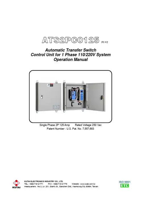
KUTAI ELECTRONICS INDUSTRY CO., LTD.ATS2PC0125 TC-V2Automatic Transfer SwitchControl Unit for 1 Phase 110/220V SystemOperation ManualSingle Phase 2P 125 Amp Rated Voltage 250 VacPatent Number : U.S. Pat. No. 7,557,683TABLE OF CONTENTSSection PageSECTION 1 : INTRODUCTION1.1 Safety Precautions (3)1.2 Products Overview (3)SECTION 2 : HARDWARE DESCRIPTION2.1 Front Panel (4)2.2 TCS2P125 Dimensions (5)2.3 Panel Cut-Out For The TC-V2 (5)SECTION 3 : FUNCTION DESCRIPTION3.1 General (6)3.2 TDNE Setting (6)3.3 TDEN Setting (6)3.4 TDEC Setting (6)3.5 TDES Setting (6)3.6 TD-OFF Setting (6)3.7 Plant Exerciser (6)3.8 Over / Under Voltage Sensing (6)3.9 Transfer Failure (6)SECTION 4 : OPERATION4.1 General (7)4.2 AUTO Mode (7)4.3 TEST Mode (7)4.4 Programming Mode (7)4.5 AC Voltage Display Adjustment (7)4.6 Specification Summary (7)4.7 System Setting Reference Table (8)SECTION 5 : INSTALLATION INSTRUCTIONS5.1 General (9)5.2 Installation On The Plate (9)5.3 TC-V2 Installation On The Door Panel (10)SECTION 6 : TYPICAL WIRING6.1 ATS2PC0125 Standard Wiring Diagram (11)SECTION 1 : INTRODUCTION1.1 Safety Precautions (Warnings)This manual covers the installation, operation and maintenance of the TCS2P125 Automatic Transfer Switch. It is intended for qualified personal only.1.2 Products OverviewThe TCS2P125 automatic transfer switch consist of two parts the TS2P125 switch and the TC-V2 electronic control unit :1.2.1 TS125 FeaturesThe contacts on the Kutai TS2P125 transfer switch are class PC, this means that it is capable of making and withstanding short circuits but is not intended for breaking short circuit current.●Rated operating Voltage:250 Vac●Rated operating Current:125 Amps●Number of poles:2P●Coil operating voltage:110 / 220 Vac +/- 20%●Compact size, light weight and low powerconsumption.●Electrically operated and mechanically held.●Manufactured using UL 94V-0 plastics.●Adjustable time delay in OFF position whentransferring.●Designed for cell-phone repeaters, and manyindustrial and home ATS applications.1.2.2 TC-V2 Digital ControllerThe TC-V2 digital control unit offers programming flexibility to customize the ATS to different customer requirements.The Controller :●Monitor normal source for full phase over and undervoltages.●Monitor emergency source for single phase overand under voltages.●Normal & emergency source voltage and frequencyparameter display.●TDEN, TDNE, TDEC and TD-OFF real timecountdown display.●Permit testing the transfer switch from the controlpanel.●Permit system testing the transfer switch with orwithout load from the front panel.●Built-in 1 to 4 weeks exerciser timer.●Permit customer plant exerciser test with / withoutload on a preset period.●Safely store customer / factory settings inpermanent memory.●Shows status and failure alarm LED’s on the frontpanel.●No need for PC connection and programmingsoftware. All settings can be made on site.●Controller can be installed next to switch orseparately on an enclosure panel.SECTION 2 : HARDWARE DESCRIPTION 2.1 Front Panel2.2 TCS2P125 Dimensions (Unit : mm)2.3 Panel Cut-Out for the TC-V2 (Unit : mm)SECTION 3 : FUNCTION DESCRIPTION3.1 GeneralOperation of the TCS2P125 electronic control.3.2 TDNE SettingsTDNE provides a time delay when transferring from N ormal to E mergency. Timing begins when the Emergency Source (generator) becomes available. TDNE:Adjustable from 0 to 99 seconds.3.3 TDEN SettingsTDEN provides a time delay when transferring from E mergency to N ormal. This permits stabilization of the Normal Power before transferring back to normal. Timing begins when the Normal Power returns and becomes available and steady.TDEN:Adjustable from 0 to 99 seconds.3.4 TDEC SettingsTDEC timer keeps the generator running without load (E ngine C ool-down) after the ATS transfer back to Normal Power. Timing begins when the transfer back to normal is completed.TDEC:Engine Cool-down - from 0 to 99 sec.3.5 TDES SettingTDES is the time delay for E ngine S tart when the Normal Source voltage is in over or under-voltage (OV or UV). If power return to normal while timing, the TDES timer resets and starts again.TDES:Adjustable from 0 to 30 seconds.3.6 TD-OFF SettingTime Delay on OFF this timer keeps the switch in the center neutral OFF position (completely disengaged) before transferring to the other side. You can preset the switch in Neutral or OFF from 0 to 18 seconds (Normally 2 to 3 sec).TD-OFF:Adjustable from 1 to 20 seconds.3.7 Plant ExerciserThis feature provides for automatic test operation of the generator. The interval is fixed at once per 1 to 4 weeks with a specific test day and time. The exerciser can be set for either testing with load or without load. When the exerciser is activated the exerciser LED (EX) on the right side of display flashes and turns on during the exercise period.3.8 Over / Under Voltage SensingThe TC-V2 constantly monitors normal & emergency power. When power falls outside the programmed voltages this LED turns RED from GREEN and flashing to show OV / UV problems.Adjustable over voltage range:110 - 280 VacOver voltage reset:When voltage falls below 10 Vac of the OV setting.Adjustable under voltage range:80 - 230 VacUnder voltage reset:When voltage exceeds 10 Vac of the UV setting.3.9 Transfer FailureWhen a transfer is made the TS125 communicates it’s position to the TC-V2 controller by using two small internal micro-switches, if this signal is not received, it will try switching 3 more times every 2 seconds or until the connection is made. A flashing light indicator and a “FAIL” signal displayed an incomplete transfer and that the ATS mechanism or wiring is defective.If the ATS fails, the TC-V2 controller stops all ATS functions and starts’ flashing until the failure is corrected and the control is reset.To reset the transfer fail alarm :1. Manually move the ATS to the correct position.2. Press any button (Auto, Program or Test) on thefront panel to reset the alarm.SECTION 4 : OPERATION4.1 GeneralThis section specifically describes the operation and functional use of the TC-V2 controller.4.2 AUTO ModeIn AUTO the TC-V2 controller automatically transfer and retransfers from source to source as directed by the pre-programmed instructions.In AUTO the controller monitors the condition of both normal and standby power sources providing the logic for the transfer operation.4.3 TEST ModeThe TC-V2 is equipped with a test pushbutton that simulates the loss of normal source. Pushing the Test key the TC-V2 will execute a test on the ATS. The TDES and TDNE programmed time delays will be performed as part of the test. There are two test modes:●Testing with load●Testing without load4.4 Programming ModeThe TC-V2 controller is fully programmable from the front panel when in the Program Mode. The build-in program buttons have multiple functions:●Real time clock displaying●Programming mode operatingTo enter programming mode, push and hold Program button for 10 seconds. In the first 10 seconds the screen showing internal real time clock and then the word “Vr 1.0” will appear s on the front display window for 2 seconds indicating the version of the software.At this time start a line by line programming sequence. To advance to the next line, push the Program button on the front panel. T o change each line’s programming parameters, press the increase (∧) and decrease (∨) buttons. When pressing and releasing the (∧) or (∨) key the displayed parameter can be increased or decreased by one. The parameter will continue to scroll if the (∧) or (∨) button is pressed and not released. Always push the “Program” button to advance to the next line or until the word “End” appears on the screen. To immediately end the programming mode, you simply push the “Program” button for 4 seconds. Then t he word “End” shows on the screen indicating the end of the programming mode. If you like to return to factory settings, stay in programming mode and simultaneously press all 3 buttons (∧), (∨) and Program buttons for 4 seconds. The TC-V2 will now automatically program itself to factory settings and the word “Au.Po” will appear on the display window.4.5 AC Voltage Display AdjustmentThe TC-V2 controller continually monitors normal & emergency power displaying volts and frequency on the front panel. (The voltage value is calibrated and adjusted at the factory). But when the ATS works on high capacitive or inductive loads the waveform distortion may cause the displayed to have slight differences from the users measuring instrument.You can adjust the display value to equal to the users own instruments, by entering the setting mode to perform adjustment the parameter. Once the adjustment is completed, the voltage sensing value will increase or decrease according to the adjusted value and display it on the screen. The TC-V2 over and under voltage protection follow the adjusted value as the actual system voltage and perform the monitoring according to the new parameter.See Table lines 2, 3, 4, 5 for voltage display setting. 4.6 Specification Summary4.7 System Setting Reference TableSECTION 5 : INSTALLATION INSTRUCTIONS5.1 GeneralThe TC-V2 controller is modular and is designed for installation next to switch or on the front door panel. A longer harness is required for door installation.5.2 Installation On The Plate5.3 Installation On The Door PanelSECTION 6 : TYPICAL WIRING6.1 ATS2PC0125 Standard Wiring Diagram (110 or 220V)___________________________________________________________________________________________ ATS2PC0125(TC-V2)11。

I n va c a r e®T o p e n d®c r o s s f I r e™s e r I e s w h e e l c h a I r sThe Invacare® Top End® Crossfire™ Series of everyday wheelchairs offers a range of frame materials and frame styles to suit a rider's individual needs and preferences. From the highly adjustable Invacare® Top End® Crossfire™ T7A Wheelchair to the Invacare® Top End® Crossfire™ Titanium Wheelchair with a fixed rear seat to floor height, you can find the ideal chair for the most energy efficient ride. The Crossfire Series Wheelchairs are the perfect fit for anyone, from the new rider to the more experienced, who wants a custom, super light chair built for performance.The Invacare ® Top End ® Crossfire ™ T7A Wheelchair features an adjustable, performance-minded, open frame design unlike any other rigid chair available today.FeaturesSuper Light 7005 Aluminum Frame MaterialModular frame design allows for ample seat to floor height adjustments without re-squaring the casters 16 degrees of back angle adjustments 3.25" of Center of Gravity adjustmentsNo charge mesh back upholstery offers more comfort in various climatesPressed bearing allow for a more controlled rotation and toeliminate caster flutterHCPCS Code: K00051. Adjustable Angle Fold Down Back2. Invacare ® Matrx ® Seating available12Model # Overall Seat Seat-to-Floor Back Front Frame CamberTubing Dimensions Dimensions Height Angle Angle Diameter CT7A Seat width 12"-20" W 16"-21" Front 75°, 79°, 83°, 70°, 75°, 0°, 3°, 6°1.12"+ 6.75" 14"-20" D 14"- 20" Rear 87°, 91° 80°, 85°.5" incrementsKnee-to- Center-of- Wheels Casters Total Weight L imitedHeel Range Gravity Weight** Capacity Warranty11.25"-20.25" 3.25" 22", 24", 25", 26" 3", 4", 5" 17.8 lb. 250 lb. 5 YearsFrame **16"x16" with 24" lightweight performance spoke wheels, Primo Hi-Pressure tires, screw-on seat upholstery, mesh back upholstery with adjustable tension, long seat support and 4" urethane casters.Please see the Owner's Manual or Invacare Configurator for complete option/specification combinations.The Invacare ® Top End ® Crossfire ™ T6 Wheelchair offers riders key adjustments such as center of gravity to keep the chair light and maintenance free. In addition, custom options such as an Ergo seat or fixed can be added to offer a more customized fit for the experienced rider.FeaturesMono-tube, open frame design making vehicle transfer easy Choice of fold down or fixed back 4.25" of Center of Gravity adjustmentFull offerings of wheel and tire optionsHCPCS Code: K00051. Ergonomic seat option2. Folding side guard3. Mesh upholstery4. Custom short fork5. No caster capsAll references to HCPCS codes: Providers are responsible for determining the appropriate billing codes when submitting claims to the Medicare program, and should 41235Model # Overall Seat Seat-to-Floor Back Front Frame CamberTubing Dimensions Dimensions Height Angle Angle Diameter CRF Seat width 12"-20" W 16"-21" Front 75°, 79°, 83° 70°, 75°, 80° 0°, 3°, 6°, 9°1.12"+ 6.75" 14"-20" D 14"- 21" Rear 87°, 91° 85°, 90° .5" incrementsKnee-to- Center-of- Wheels Casters Total Weight L imitedHeel Range Gravity Weight* Capacity Warranty11.25"-20.25" 4.25" 22", 24", 25", 26" 3", 4", 5" 19.5 lb. 250 lb. 5 YearsFrame * 16"x16" with 24" wheels, folding back, adjustable tension upholstery and 4" casters.Please see the Owner's Manual or Invacare Configurator for complete option/specification combinations.Invacare Corporation USAOne Invacare Way Elyria, Ohio 44035-4190(800) 333-6900Canada570 Matheson Blvd. E.,Unit 8Mississauga, Ontario L4Z 4G4 Canada (800) 668-5324©2012Invacare Corporation. All rights reserved.Trademarks are identified by the symbols ™ and ®. All trademarks are owned by or licensed to Invacare Corporation unless otherwise noted. Specifications are subject to change without notification. Form No. 10-070Rev. 09/12 120357Selecting the frame material of an everyday wheelchair is just as important as selecting the frame style itself. Like the Invacare ® Top End ® Crossfire T6 Wheelchair, the Invacare ® Top End ® Crossfire ™ Titanium Wheelchair offers aminimalist open frame design with simple adjustments like back angle and center of gravity–all combined in a titanium package.You can personalize your Crossfire Titanium Wheelchair with a wide variety of options and accessories. You can choose to showcase the Titanium by itself by selecting the Bead Blast Frame Finish or select one of the many paint colors.FeaturesErgonomic seat options (pictured below)Choice of fold down or fixed back 4.25" of Center of Gravity adjustmentFull offering of wheel and tire optionsHCPCS Code: K0009All references to HCPCS codes: Providers are responsible for determining the appropriate billing codes when submitting claims to the Medicare program, and shouldModel # Overall Seat Seat-to-Floor Back Front Frame CamberTubing Dimensions Dimensions Height Angle Angle Diameter CRFT Seat width 12"-20" W 16"-21" Front 75°, 79°, 83°, 70°, 75°, 0°, 3°, 6°, 9°1.12"+ 6.75" 14"-20" D 14"- 21" Rear 87°, 91° 80°, 85°, 90° .5" incrementsKnee-to- Center-of- Wheels Casters Total Weight L imitedHeel Range Gravity Weight* Capacity Warranty11.25"-20.25" 4.25" 22", 24", 25", 26" 3", 4", 5" 18.43 lb. 250 lb. 5 YearsFrame * 16"x16" with 24" wheels, folding back, adjustable tension upholstery and 4" casters.Please see the Owner's Manual or Invacare Configurator for complete option/specification combinations.1. Ergonomic seat option2. Folding side guard3. Mesh upholstery4. Custom short fork5. No caster caps41235。
ECN HISTORY LISTREV DATE DESCRIPTION APPROVED CHECKED DRAWN 1.018/06/20新發行羅宜春梁周虎許靜備注B:Dimension BxC.C:Type Standard.D:Inductance R10=0.1uh,1R0=1.0uh,100=10uh,101=100uh,102=1000uh. E:Inductance Tolerance K=±10%,L=±15%,M=±20%,N=±25%,Y=±30%F:Code Marking:Black.100and1536(15YY,36WW,follow production date).5.Specification1.Test frequency:Ls:100KHz/1.0V.2.All test data referenced to25℃ambient.3.Testing Instrument(or equ):L:HP4284A,CH11025,CH3302,CH1320,CH1320S LCR METER/Rdc:CH16502,Agilent33420A MICRO OHMMETER.4.Heat Rated Current(Irms)will cause the coil temperature rise approximatelyΔT of40℃5.Saturation Current(Isat)will cause L0to drop approximately30%.6.The part temperature(ambient+temp rise)should not exceed125℃under worst case operating conditions.Circuit design,component,PCB trace size andthickness,airflow and other cooling provisions all affect the part temperature.Part temperature should be verified in the end application.7.Special inquiries besides the above common used types can be met on your requirement.6.Material List7.Reliability and Test ConditionItemPerformanceTest ConditionOperating temperature-40~+125℃(Including self-temperature rise)Storage temperature1.-10~+40℃,50~60%RH (Product with taping )2.-40~+125℃(on board)Electrical Performance TestInductanceRefer to standard electrical characteristics list.HP4284A,CH11025,CH3302,CH1320,CH1320S LCR Meter.DCRCH16502,Agilent33420A Micro-Ohm Meter.Saturation Current (Isat)Approximately △L30%.Saturation DC Current (Isat)will cause L0to drop △L(%)Heat Rated Current (Irms)Approximately △T40℃Heat Rated Current (Irms)will cause the coil temperature rise △T(℃).1.Applied the allowed DC current2.Temperature measured by digital surface thermometerReliability TestLife TestAppearance :No damage.Impedance :within ±15%of initial value Inductance :within ±10%of initial valueQ :Shall not exceed the specification value.RDC :within ±15%of initial value and shall not exceed the specification valuePreconditioning:Run through IR reflow for 2times.(IPC/JEDECJ-STD-020DClassification Reflow Profiles)Temperature :125±2℃(Inductor)Applied current :rated current Duration :1000±12hrsMeasured at room temperature after placing for 24±2hrs.Load HumidityPreconditioning:Run through IR reflow for 2times.(IPC/JEDECJ-STD-020DClassification Reflow Profiles)Humidity :85±2﹪R.H,Temperature :85℃±2℃Duration :1000hrs Min.with 100%rated currentMeasured at room temperature after placing for 24±2hrs.Moisture ResistancePreconditioning:Run through IR reflow for 2times.(IPC/JEDECJ-STD-020DClassification Reflow Profiles)1.Baked at50℃for 25hrs,measured at room temperature after placing for 4hrs.2.Raise temperature to 65±2℃90-100%RH in 2.5hrs,and keep 3hours,cool down to 25℃in 2.5hrs.3.Raise temperature to 65±2℃90-100%RH in 2.5hrs,and keep 3hours,cool down to 25℃in2.5hrs,keep at 25℃for 2hrs then keep at -10℃for 3hrs4.Keep at 25℃80-100%RH for 15min and vibrate at the frequency of 10to 55Hz to 10Hz,measure at room temperature after placing for 1~2hrs.Thermal shockPreconditioning:Run through IR reflow for 2times.(IPC/JEDECJ-STD-020DClassification Reflow Profiles)Condition for 1cycleStep1:-40±2℃30±5min Step2:25±2℃≦0.5minStep3:125±2℃30±5minNumber of cycles :500Measured at room fempraturc after placing for 24±2hrs.VibrationPreconditioning:Run through IR reflow for 2times.(IPC/JEDECJ-STD-020DClassification Reflow Profiles)Oscillation Frequency:10~2K ~10Hz for 20minutes Equipment :Vibration checker Total Amplitude:1.52mm±10%Testing Time :12hours(20minutes,12cycles each of 3orientations)。

此PDF电子文档支持以下功能**需阅读软件支持,以AdobeReader为例。
SMOOTH-Q2说明书Z H I Y U N -C N -v 1 . 1 0Contents■产品清单产品清单 (1)■认识SMOOTH-Q2认识SMOOTH-Q2 (2)■电池及充电说明电池及充电说明 (3)■安装及调平安装手机夹 (4)安装手机 (4)调节平衡 (4)■稳定器的使用指示灯及控制按键说明 (5)工作模式说明 (6)快速待机 (8)手调定位 (9)给手机充电 (9)■APP的使用下载APP (10)如何连接 (10)APP主要功能介绍 (10)■校准与固件升级哪种情况下需要校准 (11)初始化方法 (11)六面校准方法 (11)电机微调 (13)稳定器固件升级 (13)■参数说明■免责声明与警告阅读提示 (15)警告 (15)安全操作指引 (15)■保修卡质保期限说明 (18)质保不包括 (18)为获得ZHIYUN质保服务,请按下列步骤操作 (18)■联络卡扫描二维码观看教学视频产品清单产品清单使用本产品前,请仔细检查产品包装内是否包含以下所有物品,若有缺失,请联系客服或您的代理商。
manual主机 x 1手机夹 x 1快速入门 x 1认识SMOOTH-Q2认识SMOOTH-Q21. 手机夹2. 横滚轴电机3. 俯仰轴电机4. 手机夹锁紧扳手5. 航向轴电机6. 指示灯7. 云台摇杆8. 拍照/录像键9. 电源键10. 电池盖11. M icro USB电源输出接口12. T ype-C USB充电/固件升级接口213114567128910电池及充电说明电池及充电说明SMOOTH-Q2使用21700锂电池,出厂时电池已装入电池仓。
首次使用前,请先给SMOOTH-Q2充满电以激活电池,保证产品的顺利使用。
充电方法:使用包装内提供的 Type-C USB 数据线连接电源适配器(自备,推荐5V2A规格)与稳定器手柄接口,当手柄四颗指示灯常亮(关机状态)时表示充电完成。

Translation of the original manual3-finger centric gripperPZH-SF 125Assembly and Operating ManualImprint2ImprintCopyright:This manual remains the copyrighted property of SCHUNK GmbH & Co. KG. It is solely supplied to our customers and operators of our products and forms part of the product. This documentation may not be duplicated or made accessible to third parties, in particu-lar competitive companies,without our prior permission.Technical changes:We reserve the right to make alterations for the purpose of technical improvement. Document number: 0389483Edition: 01.00 |14/08/2014|en© SCHUNK GmbH & Co. KGAll rights reserved.Dear customer,congratulations on choosing a SCHUNK product. By choosing SCHUNK, you have opted for the highest precision, top quality and best service.You are going to increase the process reliability of your production and achieve best machining results – to the customer's complete satisfaction.SCHUNK products are inspiring.Our detailed assembly and operation manual will support you.Do you have further questions? You may contact us at any time – even after purchase.Kindest Regards Yours SCHUNK GmbH & Co. KGSpann- und GreiftechnikBahnhofstr. 106 – 134D-74348 Lauffen/NeckarTel. +49-7133-103-0Fax +49-7133-103-2399**************.comTable of contents01.00|PZH-SF 125|en 3Table of contents1 About this manual (4)1.1 Warnings (4)1.2 Applicable documents (4)2 Basic safety notes (5)2.1 Intended use (5)2.2 Not intended use (5)2.3 Environmental and operating conditions (5)2.4 Product safety (6)2.4.1 Protective equipment (6)2.4.2 Demands on the top jaws (6)2.4.3 Constructional changes, attachments, or modifications (6)2.5 Personnel qualification (6)2.6 Using personal protective equipment (7)2.7 Notes on particular risks (7)3 Warranty (9)4 Scope of delivery (9)5 Accessories (10)5.1 Sensors (10)6 Technical data (11)7 Assembly (12)7.1 Mechanical connection (12)7.2 Air connection (13)7.3 Sensors (14)7.3.1 Magnetic Switch MMS 22 (14)7.3.2 Programmable magnetic switch (MMS-P) (16)7.3.3 Inductive proximity switch IN 80 (20)8 Troubleshooting (23)8.1 Module does not move? (23)8.2 The module does not travel through the entire stroke? (23)8.3 Module opens or closes abruptly? (24)8.4 The gripping force drops? (24)8.5 Module does not achieve the opening and closing times? (25)9 Maintenance and Care (26)9.1 Notes (26)9.2 Maintenance and lubrication intervals (26)9.3 Lubricants/Lubrication points (basic lubrication) (26)10 Assembly drawing (27)11 Translation of original declaration of incorporation (28)About this manual4 01.00|PZH-SF 125|enAbout this manualThis instruction is an integral part of the product and contains im-portant information for a safe and proper assembly, commission-ing, operation, maintenance and help for easier trouble shooting. Before using the product, read and note the instructions, especial-ly the chapter "Basic safety notes".WarningsTo make risks clear, the following signal words and symbols are used for safety notes.NOTICEMaterial damageInformation about avoiding material damage.Applicable documents• General terms of business• Catalog data sheet of the purchased product• Assembly and Operating manuals of the accessoriesThe documents listed here, can be downloaded on our homepage 1 1.1 1.2 Basic safety notes01.00|PZH-SF 125|en 5Basic safety notesIntended useThe product was designed to grip and to temporarily and securely hold workpieces and objects.The product is intended for installation in a machine/system. The requirements of the applicable guidelines must be observed and complied with.The product may be used only in the context of its defined applica-tion parameters (☞ 6, Page 11).The product is designed for industrial use. To use this unit as intended, it is also essential to observe the technical data and installation and operation notes in this manual and to comply with the maintenance intervals.Not intended useUse which is not specified as an intended use is for instance when the product is for example used as a pressing tool, stamping tool, lifting tool, guide for tools, cutting tool, tensioning mean, boring tool.Environmental and operating conditions• Make sure that the product and the top jaws are a sufficient size for the application.• Observe Maintenance and lubrication intervals(☞ 9.2, Page 26).• Make sure that the environment is free from splash water and vapors as well as from abrasion or processing dust. Exceptions are products that are designed especially for contaminated en-vironments.2 2.1 2.2 2.3 Basic safety notes6Product safetyDangers arise from the product, if:• the product is not used in accordance with its intended purpose. • the product is not installed or maintained properly.• the safety and installation notes are not observed. Avoid any manner of working that may interfere with the function and operational safety of the product.Wear protective equipment.NOTEMore information are contained in the relevant chapters.Protective equipmentProvide protective equipment per EC Machinery Directive.Demands on the top jawsArrange the top jaws such that when the product is depressurized it can reach one of the end positions either open or closed and therefore no residual energy can be released when changing the top jaws.Constructional changes, attachments, or modificationsAdditional drill holes, threads, or attachments that are not offered as accessories by SCHUNK may be attached only with permission of SCHUNK.Personnel qualificationThe assembly, initial commissioning, maintenance, and repair of the product may be performed only by trained specialist person-nel. Every person called upon by the operator to work on the product must have read and understood the complete assembly and operating manual, especially the chapter "Basic safety notes" ( 2, Page 5). This applies particularly to personnel only used oc-casionally, such as maintenance personnel.2.4 2.4.1 2.4.2 2.4.3 2.5 Basic safety notes01.00|PZH-SF 125|en 7Using personal protective equipmentWhen using this product, observe the relevant industrial safety regulations and use the personal protective equipment (PPE) re-quired!• Use protective gloves, safety shoes and safety goggles. • Observe safe distances.• Minimal safety requirements for the use of equipment.Notes on particular risksGenerally valid:• Remove the energy supplies before installation, modification, maintenance, or adjustment work.• Make sure that no residual energy remains in the system. • Do not move parts by hand when the energy supply is con-nected.• Do not reach into the open mechanism or the movement area of the unit.• Perform maintenance, modifications, and additions outside the danger zone.• Secure the product during all operations against uncontrolled activation.• Take a precautionary approach by maintenance and disassembly. • Only specially trained staff should disassemble the product. 2.6 2.7 Basic safety notes8 01.00|PZH-SF 125|enAccessories01.00|PZH-SF 125|en 9WarrantyIf the product is used as intended, the warranty is valid for 24 months from the date of delivery from the production facility un-der the following conditions: • Observe the applicable documents (☞ 1.2, Page 4)• Observance of the ambient conditions and operating conditions (☞ 2.3, Page 5)• Observe the maximum mileage (☞ 6, Page 11)• Observance of the maintenance and lubrication intervals (☞ 9, Page 26)Parts touching the workpiece and wearing parts are not part of the warranty.Scope of deliveryThe scope of delivery includes:• 3-finger centric gripper PZH-SF in the ordered model. • Accessory pack3 4 Accessories10AccessoriesA wide range of accessories are available for this module.For information about which accessories can be used with the ap-propriate product version ☞ catalog.SensorsOverview of the compatible sensors• Exact type designation of the compatible sensors see ☞ catalog. • If you require further information on sensor operation, contact your SCHUNK contact person or download information from our homepage.• To use the proximity switch IN, the gripper must be retrofitted with a special mounting kit. This mounting kit is available from SCHUNK. For types that can be ordered, see catalog.5 5.1 Technical data 6Technical dataWarrantyThe most recent version applies.Assembly12AssemblyMechanical connectionThe values relate to the entire bolting surface.Requirements for levelness of the bolting surface (Dimensions in mm)The module can be mounted from the front or the rear.Fig. 1 Mounting the gripperMaximal screw-in depth of the fastening screws provided by thecustomer.NOTE•When mounting from the back, fasten the module by means ofthe provided fixing bore.•Fasten the module using the provided mounting holes.•Fasten the top jaws using the provided mounting holes.77.1Check the evennessof the bolting surfaceMountingAssembly 7.2Air connectionDamage to the gripper is possible!If the maximum permissible finger weight or the permissible mass moment of inertia of the fingers is exceeded, the gripper can bedamaged.•A jaw movement always has to be without jerks and bounce.•You must therefore implement sufficient reduction and/ordamping.•Observe the diagrams and information in the catalog data sheet.Observe the requirements for the air supply( 6, Page 11).Fig. 2 Air connectionsThread diameter of the air connections•Open only the air connections that are needed.•Close unused main air connections using the screw plugs fromthe enclosed pack.•For a hose-free direction connection, use the O-rings from theenclosed pack.Assembly14SensorsThe module is prepared for a number of sensors. Other sensorscan be used with a mounting kit.•If you require further information on sensor operation, contactyour SCHUNK contact person or download information fromour homepage.•Technical data for the sensors can be found in the data sheets(included in the scope of delivery).Magnetic Switch MMS 22Fig. 3NOTICESensor can be damaged during assembly.Do not exceed the maximum tightening torque of 10 Ncm for theset screws.NOTEFerromagnetic material changes the switching positions of thesensor. For example: Adapter plate made of ordinary steel.At ferromagnetic adapter plates:•The module must firstly be mounted on the adapter plate•Then, the positions of the magnetic switch have to be set7.37.3.1Assembly Positioning themagnetic switchFig. 4Gripper open:1 Move gripper to “Open” position.2 Slide the magnetic switch 1 (1) into the groove (4) until itcomes into contact with the housing.3 Slowly pull the magnetic switch 1 (1) back until it switches.4 By tightening the set screw on the magnetic switch, fix themagnetic switch 1 (1) in this position in the groove (4).5 Close the gripper and open again to test the function.Gripper closed:1 Move gripper to “Closed” position.2 Slide the magnetic switch 2 (2) into the groove (3) toward thecenter of the gripper until it switches.3 By tightening the set screw, fix the magnetic switch 2 (2) inthis position in the groove (3).4 Open the gripper and close again to test the function.Part gripped (O.D. gripping):1 Clamp the part to be gripped.2 Slide the magnetic switch 2 (2) into the groove (3) toward thecenter of the gripper until it switches.3 By tightening the set screw, fix the magnetic switch 2 (2) inthis position in the groove (3).4 Open the gripper and close again to test the function.Assembly16Part gripped (I.D. gripping):1 Clamp the part to be gripped.2 Slide the magnetic switch 1 (1) into the groove (4) until itcomes into contact with the housing.3 Slowly pull the magnetic switch 1 (1) back until it switches.4 By tightening the set screw, fix the magnetic switch 1 (1) inthis position in the groove (4).5 Close the gripper and open again to test the function.Programmable magnetic switch (MMS-P)Fig. 5 Magnetic switch (MMS-P 22)Fig. 6 Connection diagram PNP-4 conductor (MMS-P 22)7.3.2AssemblyTypes available for order (see catalog):•MMS-P 22-S-M8-PNP• MMSK-P 22-S-PNP• V2-M8-4-2XM8-3The MMSK-P 22-S-PNP features a cable with open strands so thatit can be connected by means of terminal contacts.The V2-M8-4-2XM8-3 distributor is used to convert the 4-pin con-nector plug of the MMS-P 22-S-M8-PNP sensor to two standardM8 plugs with 3 pins each.Mounting of the sensorSensor can be damaged during assembly.• Do not exceed the maximum tightening torque of 10 Ncm forthe set screws.NOTEFerromagnetic material changes the switching positions of thesensor. For example: Adapter plate made of ordinary steel.At ferromagnetic adapter plates:•The module must firstly be mounted on the adapter plate•Then, the positions of the magnetic switch have to be setFig. 71 To relieve the cable, the electronics have to be fixed in placeusing cable ties (7).There are ribs (6) in place on the electronics for mountingpurposes.Assembly18Fig. 8 2 Turn in the sensor (1 - 4).ORPush the sensor axially into the slot until it contacts the stop (5). 3 Fix the sensor with an Allen wrench (6).1 Keep the Teach-Button (4) pressed for2 seconds.⇨ After 2 seconds LED 1 (3) is flashing2 Move the gripper into position 1 (e.g. "open").3 Press the Teach-Button (4) briefly.⇨ LED 1 (3) lights up and LED 2 (5) is flashing.4 Move the gripper into position 2.⇨ LED 1 (3) should turn out as soon as the switching point 1 is left. 5 Press the Teach-Button (4) briefly.⇨ LED 2 (5) lights up.⇨ The switching points are set.AssemblyThe hysteresis to both switching points will be adjusted automati-cally corresponding to the characteristics of the magnetic field.The user can set the switching and trigging points of each position a little bit closer than for the automatic mode. The trigging point is closer to the switching point. At the same time the susceptibility to trouble and damage increases. In the mode of the lowest hystere-sis, an error signal (such as jitter or untimely switch off) can be avoided, if the sensor is protected against all types of disturbances (i.e. by shielding). Frequent types of disturbances are change in temperature and electro-magnetic influences.Within the closest fine-teach mode, SCHUNK cannot guarantee EMC-compatibility any more.The hysteresis adjustment is used for the manual adjustment of the switching points (if necessary).In case that the hysteresis automatically determined by the sensor should be too high or too low after “the adjustment of the switch-ing points”, you may correct the value as follows.The sensor avoids a too small hysteresis during hysteresis adjust-ment.The smallest detectable stroke difference is 10% of the rotation angle per finger.1 Press the Teach-button (4) for 5 seconds.⇨ LED 1 (3) will flash up after 2 seconds.⇨ LED 1 will stop after 5 seconds.2 Release the Teach-button.3 Move the gripper to the "switch-off point for switching point 1" position.4 Press the Teach-Button (4) briefly.LED 1 (3) will light up twice.5 Move the gripper to the "switch-off point for switching point 2" position.6 Press the Teach-Button (4) briefly.⇨ LED 2 (5) will light up twice.⇨ The mounting of the sensor MMS-P is completed.Adjusting the hysteresisAssembly20Inductive proximity switch IN 80Fig. 9 Connection example for IN 80The inductive proximity switches used are equipped with reversepolarity protection and are short-circuit-proof.Make sure that you handle the proximity switches properly:•Do not pull on the cable.•Do not allow the sensor to dangle from the cable.•Do not overtighten the mounting screw or mounting clip.•Please adhere to a permitted bend radius of the cable. (☞ catalog)•Avoid contact of the proximity switches with hard objects andwith chemicals, in particular nitric acid, chromic acid and sul-phuric acid.The inductive proximity switches are electronic components,which can react sensitively to high-frequency interference or elec-tromagnetic fields.•Check to make sure that the cable is fastened and installed cor-rectly. Provide for sufficient clearance to sources of high-frequency interference and their supply cables.•Parallel switching of several sensor outputs of the same type(npn, pnp) is permissible, but does not increase the permissibleload current.•Note that the leakage current of the individual sensors(ca. 2 mA) is cumulative.7.3.3AssemblyTo mount the proximity switches IN, the gripper must be retrofit-ted with a special mounting kit. This mounting kit is available from SCHUNK. For types that can be ordered, see catalog.Fig. 101 Fasten both brackets (1) with 2x screws (2) on the housing.2 Screw in the set screws (6) halfway into the not yet assembledmount (3).3 Place both mounts (3) on the base jaws (10); set screws (6) are not yet to be tightened.4 Fasten both switching lugs (5) with screws (4) on the mounts (3).The switching points of the “opened” and “closed” position must be set.Gripper open:1 Push the proximity switch 1 (8) into the bracket (1) to the stop.2 Fasten the proximity switch by tightening the screw (9).3 Move gripper to “Open” position.4 Turn the corresponding mount (3) with the switching lug (5) until the proximity switch (8) switches.5 Fix the position of the switching lug by tightening the set screw (6).Assembly of the mounting kit Mounting of the proximity switchAssembly22 Gripper closed:1 Push the proximity switch2 (7) into the bracket (1) to thestop.2 Fasten the proximity switch by tightening the screw (9).3 Move gripper to “Closed” position.4 Turn the corresponding mount (3) with the switching lug (5)until the proximity switch (7) switches.5 Fix the position of the switching lug by tightening the setscrew (6).Part gripped (O.D. gripping):1 Push the proximity switch2 (7) into the bracket (1) to thestop.2 Fasten the proximity switch by tightening the screw (9).3 Clamp the part to be gripped.4 Turn the corresponding mount (3) with the switching lug (5)until the proximity switch (7) switches.5 Fix the position of the switching lug by tightening the setscrew (6).Part gripped (I.D. gripping):1 Push the proximity switch 1 (8) into the bracket (1) to the stop.2 Fasten the proximity switch by tightening the screw (9).3 Clamp the part to be gripped.4 Turn the corresponding mount (3) with the switching lug (5)until the proximity switch (8) switches.5 Fix the position of the switching lug by tightening the setscrew (6).TroubleshootingTroubleshootingModule does not move?The module does not travel through the entire stroke?8 8.1 8.2Troubleshooting2401.00|PZH-SF 125|enModule opens or closes abruptly?The gripping force drops?8.3 8.4Troubleshooting 8.5Module does not achieve the opening and closing times?Maintenance and Care26Maintenance and CareNotesOriginal spare partsWhen replacing damaged parts (wearing parts/spare parts) onlyuse SCHUNK original spares.Replacement of housing and rotary flangeThe and the in the housing are matched to each other. To replace these parts, send the entire module to SCHUNK with a repair order or order the housing with base jaws as a set.Maintenance and lubrication intervalsAt ambient temperature above 60°C the lubricants canharden faster.•Interval decrease accordingly.Maintenance- and lubrication intervalLubricants/Lubrication points (basic lubrication)We recommend the lubricants listed.During maintenance, treat all greased areas with lubricant. Thinly apply lubricant with a lint-free cloth.99.19.29.3Assembly drawing 10Assembly drawingFig. 11* Positions are adapted to each other and may not be replaced by the customer.** Wearing part, replace during maintenance.Included in the seal kit. Seal kit can only be orderedcompletely.Translation of original declaration of incorporation2801.00|PZH-SF 125|enTranslation of original declaration of incorporationThe manufacturer agrees to forward on demand the relevant technical documentation for the partly completed machinery to state offices.The special technical documents according to Appendix VII, Part B belonging to the in-complete machine have been compiled.Person authorized to compile the technical documentation: Robert Leuthner, Address: see manufacturer's address11。
Cart P roduct S electorQuick S tart G uide1.I ntroductionCart Product Selector i s an extension which allows the customer to selectively choose products present in the cart and proceed to checkout with the selected products,automatically removing the unwanted products.Why C art P roduct S elector E xtension?Cart Product Selector makes the purchase flow user friendly when additional unwanted products are in the shopping cart.With Cart Product Selector,the customer can simply select the product(s)that he/she wishes to purchase from the cart,without worrying about the unwanted item(s)and can quickly proceed to checkout with the selected items,where the computation of the order total,tax and shipping amount will be done on the basis of the products selected by the customer.Also,the remaining unwanted items of the cart will be removed once the customer proceeds to checkout,hence refreshing the c art f or t he n ext p urchase.Cart product selector extension will be very helpful in the scenarios where a customer has added too many items into his shopping cart but the customer has to purchase only a few products out of them, then the customer either has to remove each product in cart individually or move each product into wish list.Now the customer simply has to select the items which he wants to purchase and proceed to checkout.Key F eatures:●Allows the customer to select and proceed with only the required product(s),without the needof m anual e fforts o f r emoving u nwanted i tems f rom t he c art.●Automatically c lears t he u nwanted i tems f rom t he c art a fter p roceeding t o c heckout.●Automatically u pdates t he c ount o f a dded p roducts d isplayed o n t he m ini-cart.●Automatically calculates product price and tax for selected product(s)on checkout page andprovides f inal p ayment d etails t o t he c ustomer.2.I nstallationInstallation R equirements:1.Magento2i nstalled o n t he h osting s erver.2.Access t o t he M agento A dmin d ashboard.mand l ine a ccess t o t he h osting s erver.4.Knowledge o f b asic L inux c ommands.Installation S teps:1.Login i nto y our h osting s erver w here M agento2i s i nstalled.2.Switch t o M agento i nstallation d irectory o n t he s erver.cd$MAGENTO_INSTALL_DIR/3.Create t he I nfoBeans d irectory.mkdir-p$MAGENTO_INSTALL_DIR/app/code/Infobeans4.Extract t he d ownloaded c ode o f t he E xtension a nd c opy t he M ODULENAME m odule i nto t hecreated d irectory:cp-R$MODULENAME_MODULE$MAGENTO_INSTALL_DIR/app/code/Infobeans5.Run t he b elow m entioned c ommand t o c omplete t he i nstallation o f t he m odule a nd c lear s taticcontent.$PHP_INSTALL_DIR/php$MAGENTO_INSTALL_DIR p hp b in/magento m odule:enable--clear-static-content I nfobeans_CartProductSelector$PHP_INSTALL_DIR/php$MAGENTO_INSTALL_DIR p hp b in/magento s etup:upgradeing t he c ommand l ine u tility,c lear t he M agento c ache,t o e nsure t he i nstalled m odule i svisible a nd a ctive.$MAGENTO_INSTALL_DIR/bin/magento c ache:clean7.Give r equired p ermissions t o M agento r oot d irectory.Using t he M agento A dmin P anel1.Log i nto t he M agento A dmin P anel.2.Click t hrough t o[System->C ache M anagement].3.In t he t op l eft h and c orner,s elect“Refresh”f rom t he d ropdown.4.Click o n t he“Select a ll”c heckbox f rom t he t able h eader.5.Now c lick“Submit”b utton.6.Congratulations!Y ou h ave s uccessfully i nstalled t he e xtension.3.S creenshotsAfter i nstallationGo t o t he a dmin:Screenshot001:C art P roduct S elector C onfiguration o n a dmin.Frontend:Go t o t he C art P age:Screenshot002:C art P roduct S elector o n C art P ageSelect p roduct(s)i n C art p age:Screenshot003:S elect P roduct o n C art P age Proceed t o C heckout P age:Screenshot004:S elected p roducts o n C heckout P ageGo t o O rder R eview:Screenshot005:S elected p roduct o n O rder R eview P age11。
Wave Bathing & Transfer SystemZ210, Z220, & Z230 Product ManualZ210, Z220 & Z230 Product ManualContentsImportant information 3Safety messages 4Recommended use and item dimensions 5Check your order 6Basic componentsLegs 6Back 7Seat 7Seat with calf rest 7Head blocks 8Soft fabric cover 8Chest strap and leg straps 8 AccessoriesTub stand 9Shower stand 10Tub transfer base 11-12Conversion kit 12 Operation and maintenance 13Cleaning and warranty 14Materials and user modifi cations 15© 2018 Rifton Equipment2IMPORTANTPlease save this product manual for future reference. Additional copies areavailable at /customer-service/product-manuals.3• Thoroughly read and understand the information in this product manual beforeattempting to use this product. If the procedures and instructions in this product manualare not followed, serious injury or death could occur.• A qualifi ed professional must assess the appropriateness and safety of all equipment foreach user.• This product is intended for use by clients of unreliable judgment. Adult supervision isrequired at all times.• To prevent falls and injuries:○Do not use this product on rough and uneven terrain, around swimming pools, ornear stairways.○Ensure the appropriate use of straps and supports at all times. Straps and supportsare provided for the safety of the user and must be carefully adjusted for comfort andsecurity.○Tighten all adjustment knobs before use and immediately after making anyadjustments.• Do not use this product for clients outside the height and weight limits specifi ed in thismanual.• To prevent pinching or crushing, ensure that all hands and feet are clear of moving partsduring adjustment.• To prevent structural failure, which may result in serious injury or death:○Inspect this product and accessories regularly for loose or missing screws, metalfatigue, cracks, broken welds, missing attachments, general instability or other signsof excessive wear.○Immediately remove this product from use when any condition develops that mightmake operation unsafe.○Do not use Rifton components or products for any purpose other than theirintended use.• To prevent drowning, use extra caution when using the bath chair in a bathtub.4Recommended useThe Rifton Wave bathing and transfer system is a Class 1 medical device. It is intendedto provide a stable, quick-drying seat for bathing or showering for individuals with disabilities. Adjustments and additional supports are available for the safety and comfort of the user. The tub transfer base enables easier transfers over the bathtub for large users.Seat depth10½ (27)13 (33)17 (43)Seat width15 (38)15 (38)17½ (44)Back height23 (58)26½ (67)32 (81)Seat height2/7 (5/18)2/7 (5/18)2/7 (5/18)Seat height including tub stand12½-18½ (32-47)12½-18½ (32-47)12½-18½ (32-47)Seat height including shower stand27½ (70)27½ (70)27½ (70)Seat height including transfer base with long leg inserts21-26 (53-66)24½ - 29½ (62-75)21-26 (53-66)24½ - 29½ (62-75)21-26 (53-66)24½ - 29½ (62-75)Length of mesh area when fl at(without calf rest)35 (89)41 (104)50½ (128) Length of mesh area when fl at(with calf rest)42½ (108)49 (124)61 (155) Width of base18 (46)18 (46)21 (53) Length of base when fl at29½ (75)29½ (75)29½ (75) Tub stand height (legs fl at)8 (20)8 (20)8 (20) Tub stand length (legs fl at)39 (99)39 (99)39 (99) Tub stand width (legs fl at)17½ (44)17½ (44)17½ (44) Shower stand height22 (56)22 (56)22 (56) Shower stand width27 (69)27 (69)27 (69) Shower stand length34 (86)34 (86)34 (86) Tub transfer base footprint28 x 30 (71 x 76)28 x 30 (71 x 76)28 x 30 (71 x 76)Max. tub height for transfer base with long leg inserts 20 (51)24 (61)20 (51)24 (61)20 (51)24 (61)Max. working load - Lbs. (kg)75 (34)150 (68)250 (114)Back and seat angle adjustments0˚, 15˚, 30˚, 45˚, 60˚, 75˚User and item dimensions56Check your orderYour Wave bathing and transfer system comes with the bath chair completely assembled. You will only need to attach it to whatever base you are using, and position the backrest, seat and headblocks appropriately before use.If your shipment is incomplete or in any way damaged on arrival, please call Customer Service, 800.571.8198.Figure 6a132Figure 6bThe Wave bath chair comes in small, medium, and large sizes. It can be used with or without a tub stand, shower stand, or tub transfer base. A soft fabric cover with padding is part of the standard product.LegsThe bath chair legs adjust to raise or lower the chair by 7" (18 cm). You can also get an intermediate height by raising the front legs only.Figure 6a: To raise or lower the chair:1. Pull crossbar outward.2. Rotate legs up or down.3. Push crossbar in to engage.Figure 6b: The bath chair folds fl at forstorage.Basic itemFigure 7aFigure 7bBackFigure 7a: The bath chair back adjusts in15° increments with a one-hand latch. Toadjust the back:1. Squeeze gray handle (A) up behindchair back.2. Rotate back to desired position.3. Release gray handle to engage thelatches at desired angle.SeatFigure 7b: The seat angle adjusts in 15°increments. Increasing the angle can helpprevent the user from sliding forward on theseat. To adjust the seat:1. Pull the two gray triggers (B) under thefront edge of the seat towards you.2. Rotate the seat to the appropriateposition.3. Release both triggers to engage thelatches.Seat with calf restTo prevent seriousinjury, fold calf restdown during transfers. Full weight oncalf rest may break it or tip chair.Figure 7c: If you purchased the calf restoption, it is attached to the seat front andadjusts independently of the seat. To adjustthe calf rest:1. Hold the calf rest fi rmly while pressingthe gray buttons (C) on both sides.2. Adjust the calf rest to the desired angle.3. Release both gray buttons engagelatches.Figure 7cABC78Head blocksFigure 8a: Slide the head blocks in and outon the strap to adjust spacing. They can also be positioned at any height using the hook and loop fasteners at the back.Soft fabric coverThe fabric cover for the bath chair is made of soft polyester knit for comfort. Extra padding between the fabric and the frame softens surface contact.Chest strapsTo preventstrangulation, ensurecorrect adjustment and positioning of the chest strap at each use.Two choices of chest straps are available in soft polyester knit material.Figure 8b: The standard chest strap’s topportion encircles the user, and the back portion attaches around the bath chair back with a buckle.Figure 8c: The chest strap with lateral positioning also buckles around the backof the chair, but has additional side pieces (A) that stabilize the chest strap laterally.Leg strapsFigure 8d: Fasten the leg straps to the seatwith the buckle underneath. Use the legstraps to secure the user’s legs.Figure 8b: standard chest strapFigure 8aFigure 8c: chest strap with lateral positioningFigure 8dA9Figure 9bFigure 9cFigure 9aAccessoriesTub standTo prevent falls, make sure all fourchair legs are fi rmly latched in the sockets on the stand before using the tub stand.Figure 9a: The tub stand raises the bathchair to a seat height of either 12½" (32 cm) or 18½" (47 cm), depending on whether the tub stand legs are raised or lowered (see page 6).Figure 9b: To attach the chair onto the tubstand:1. Rotate front and back bath chair legs down into the vertical position (see page 6).2. Insert the legs into the four sockets.3. Press down fi rmly until the latches click into place.To release :Figure 9c:1. Press down on both gray latches at one end of the tub stand.2. Firmly lift up the bath chair, so that the two latches on the other end disengage.The tub stand is not sized to fi t onto the showerstand or another tub stand.NOTICE10Figure 10aFigure 10bShower standTo prevent falls, make sure all fourchair legs are fi rmly latched in the sockets on the stand before using the shower stand.Figure 10a: The shower stand puts the bathchair on wheels at standing height for the caregiver. All three sizes of bath chair fi t on the same shower stand.To attach:Figure 10b:1. Rotate front and back bath chair legs down into the vertical position (see page 6).2. Insert bath chair legs into the shower stand sockets.3. Press down fi rmly until the gray latches (A) engage.To release :Figure 10c:1. Press down on both gray latches (A) at one end of the shower stand.2. Lift up the bath chair, and the latches at the other end will disengage.Figure 10cAA11Figure 11cFigure 11aFigure 11bABCFigure 11dFigure 11eDTub transfer baseTo prevent falls and injuries:• Make sure front wheels are locked during transfers.• Make sure both front and rear bath chair legs are securely latched onto the base.The tub transfer base enables clients in the bathchair to be transferred over a bath tub with zero lifting.Figure 11a: To set up base:1. Squeeze latches (A) on underside of base at both ends, fold legs out until they click into place.2. Place legs of the wider end of the transfer base in bathtubFigure 11b: To install bath chair onto tubtransfer base:1. Rotate front and back bath chair legs up into the horizontal position (see page 6).2. Slide crossbar of front legs under the white hook (B) on the narrower end of the transfer base.3. Push back of bath chair down fi rmly to latch bar of rear bath chair legs under the gray latch (C).Transfers:1.Figure 11c: To rotate top platform, press either of the gray buttons (D) at one of the front corners. Start transfers with bath chair facing out from the tub.2. Figure 11c: Pull tub transfer base forward if desired and lock wheels. This allows room to use a mechanical lift if needed.3. Transfer user onto bath chair seat and secure with strap(s).4. Figure 11d: Release wheel brakes, push tub transfer base over the tub and lock wheels.5. Figure 11e: Rotate bath chair 90°, lifting user’s legs over side of tub.12Figure 12aSwitching your tub transfer base from counterclockwise to clockwise confi guration (or the reverse):1. Figure 12a: Remove the two screws with a 5/32” hex tool. Lift the top platform off. Remove the two plastic glides (A) and the plastic plug (B) from the third hole (easier to do from the back).2. Figure 12b: Pry out the long plastic stop (C) from the groove as shown. You may need a screwdriver or other tool to pull it out.3. Figure 12c: Insert the plastic stop (C) on the other end of the same groove as shown. Then slide the rear slider (D) over until it hits the stop.4. Figure 12d: Set the top platform on again; now the rear slider (D) should be in the other rear hole as shown.5. Insert the two screws again and tighten with the 5/32” hex tool. Press the plastic plug (B) into the empty third hole. Now your tub transfer base is ready to use in the opposite confi guration.Conversion kitFigure 12e: The conversion kit convertsthe small pink or blue Rifton bath chairs to a medium size, tool-free. Call customer service to order.Figure 12bFigure 12cFigure 12dABCCDBFigure 12eWithout calf rest With calf restDOperationThe Rifton bath chair is intended for use in a bathtub or shower. It’s adjustability and accessories enable bathing or showering clients with a wide range of disabilities. Theseat and back angles adjust easily to accommodate positioning needs. Head Blocks,chest straps, and leg straps are designed for the safety of the user, and must be carefullyadjusted for comfort and security. The bath chair legs can be placed securely in twopositions to raise or lower the bath chair prior to use.MaintenanceThis product is designed and tested for an expected life of 5 years when used andmaintained in accordance with this manual. At all times, users must ensure that theproduct remains in a safe and useable condition, including regular maintenance andinspections as specifi ed in this manual.To prevent structural failure, which may result in serious injury or death:• Inspect this product and accessories regularly for loose or missing screws, metalfatigue, cracks, broken welds, missing attachments, general instability or other signs of excessive wear.• Immediately remove this product from use when any condition develops that mightmake operation unsafe.• Do not use Rifton components or products for any purpose other than theirintended use.• Replace or repair components or products that are damaged or appear to be unstable.• Use only Rifton authorized replacement parts. Order information for replacement partsis provided on the back of this product manual.1314Figure 14aCleaningThe Rifton bathing system is designed for easy cleaning.Figure 14a: Remove the fabric cover byadjusting both the seat and back to a near vertical position and pulling cover from frame, seat part fi rst.Fabric parts should be washed and dried at a warm (100°F/40°C) setting. Use mild detergent. Rinse well. Disinfect frame and fabric with a commercial disinfectant, or a solution of up to 10% bleach. Rinse well. The straps with hook and loop closures may be laundered. Engage the closures before washing. Do not iron.Excessive use of bleach and high temperatures may damage the fabric. Do not iron.Tub stand, shower stand, tub transfer base and frame parts may be cleaned using normal cleaning products. Casters will give the best performance if cleaned regularly by spraying from underneath with a high-pressure water hose. Do not use chemicals or lubricants.Warranty statementIf a Rifton product breaks or fails in service during the fi rst year, we will replace itfree of charge.Materials• Steel hardware items (nuts, bolts, screws, etc) are stainless steel.• Fabric is a polyester knit, cushioned with polyester spacer fabric, with nylon hook andloop fasteners.• Frames are made with powder-coated aluminum.• Plastic components are typically injection molded from a variety of industrial resins.All materials are latex, lead and phthalates free.User modifi cationsTo prevent serious injury or death, do not modify or alter Riftonin conjunction with products from other manufacturers. Rifton does not accept responsibility for any modifi cations or alterations made to our components orproducts after they leave our premises. Customers modifying or altering ourcomponents or products, or using them in conjunction with products from othermanufacturers, do so at their own risk.15ZC24 ECO3504 Revision01 Find letters of medical necessityand more information at:/wave16。
D I S C O公司产品系列介绍Company Document number:WTUT-WT88Y-W8BBGB-BWYTT-19998DISCO公司产品介绍一:自动切割机什麽是自动切割机?是指被加工物的安装及卸载作业均采用手动方式进行,只有加工工序实施自动化操作的切割机。
在有些机型上也可实施自动化位置校准作业。
但在机器内部没有配置清洗、乾燥装置.位置校准切割操作人员以手动方式将被加工物安装到工作盘上。
3000系列的设备可自动实施位置校准作业。
300系列和500系列的设备,由操作人员使用显微镜进行切割位置对准作业。
操作人员只要按下开始按钮,机台就可在位置校准工序识别出的切割道进行切割加工。
300系列 - Automatic Dicing Saw300系列切割机/切断机,利用人工方式完成加工物的安装调整及识别切割位置的校准作业,并且在设计上力求节省占地空间,使该机型的外形结构显得简洁精巧。
另外,为了满足各种加工要求,在最大加工物尺寸和加工精度等方面,均拥有种类丰富的产品群。
For 6" frameDAD321DAD322DAC351/DAD361设备概要适用 6"加工物的自动切割机DAD321的改良机型,産能更高追求高精度的切断机和自动切割机最大加工物尺寸160 x 1606"(边长6"方形)*1DAC351: 153 x 153 DAD361: 160 x 160适用框架2-6-1DAC351: - DAD361: 2-5, 2-6X轴可切割范围(mm)192160192进刀速度有效范围(mm/s)- 300 - 500 - 300Y轴可切割范围(mm)162最小步进量(mm)定位精度(mm)以内/160(单一误差)以内/5以内/160(单一误差)以内/5光学尺最小分辨率(mm)-Z轴有效行程(mm)( 2"切割刀片)( 2"切割刀片)( 2"切割刀片)最小移动量(mm)重复定位精度(mm)可使用的最大58发出订单。
北京雷根生物技术有限公司
多聚甲醛溶液(16% PFA)
简介:
固定的目的在于保存细胞和组织的原有形态结构,固定剂能阻止内源性溶酶体酶对自身组织和细胞的自溶、抑制细菌和霉菌的生长。
固定液分为醛类固定液、汞类固定液、醇类固定液、氧化剂类固定液、苦味酸盐类固定液等,较为常用的是醛类中的福尔马林、醇类中的乙醇。
Leagene 多聚甲醛溶液(16% PFA)主要由多聚甲醛、磷酸盐、去离子水组成,pH 为7.4,该固定液适合于绝大多数组织和细胞的固定。
16%多聚甲醛溶液是免疫组织化学和培养细胞的固定液之一,常与其他固定剂混合用,其浓度较高,如单独使用应采用磷酸盐缓冲液稀释至4%。
组成:
操作步骤(仅供参考):
1、 一般组织固定时间控制在4~12h ,大标本应适当延长固定时间,培养细胞或细胞爬片固定时间控制在10~15min ,特殊情况除外。
注意事项:
1、 多聚甲醛溶液(16% PFA)有一定刺激性和腐蚀性。
一经开启,储存过久固定效果易下降。
2、 避免过度延长固定时间,否则易引起细胞内生物大分子过度交联。
3、 组织取材的厚度不同,固定时间也不同。
4、 固定液的容量应足够,一般固定液与组织块的体积比率应大于10:1。
5、 温度对固定的影响很明显,提高温度可以加速固定作用,但温度不宜过高。
6、 取出新鲜组织后,应及时固定,无法及时固定时,应保存于生理盐水中及时送检。
有效期: 12个月有效。
相关:
编号 名称 DF0131 Storage 多聚甲醛溶液(16% PFA) 500ml 4℃ 避光 使用说明书 1份
编号 名称 DC0032 Masson 三色染色液 TC0699 植物总糖和还原糖检测试剂盒(硝基水杨酸法)。