米亚基大电流监测仪MM-315B说明书
- 格式:pdf
- 大小:1.50 MB
- 文档页数:34


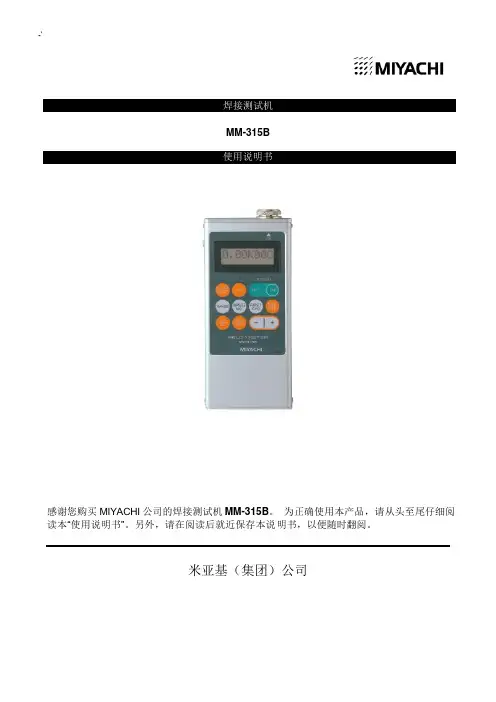
-`焊接测试机MM-315B使用说明书感谢您购买MIYACHI 公司的焊接测试机MM-315B。
为正确使用本产品,请从头至尾仔细阅读本“使用说明书”。
另外,请在阅读后就近保存本说明书,以便随时翻阅。
米亚基(集团)公司目录1. 特别注意事项 (1)(1)安全注意事项 (1)(2)使用注意事项 (4)2. 前言 (1)(1)主体及附属品 (1)(2)非附随品 (1)3. 焊接测试机的各部件名称 (1)4. 关于检测 (1)(1)环形线圈的设置 (1)(2)接通电源 (2)(3)确认检测条件 (3)(4)检测条件的设置 (4)a. 范围的设置 (4)b. 脉冲NO.的设置 (5)c. NOTE1.脉冲NO.设置及显示 (6)d. 开始周期的设置 (8)e. 最终周期的设置 (9)(5)通电角的确认 (10)(6)变频器焊接机的检测 (11)(7)关于全脉冲储存 (13)(8)关于半周期单位的显示 (16)(9)关于强制检测周期 (16)(10)关于超值显示 (16)5. 按钮及其功能 (1)6. 规格 (1)7. 外观图 (1)8. 关于充电方法 (1)(1)连接主机和充电器 (1)(2)关于充电时期 (1)(3)关于充电中的检测操作 (1)(4)关于镍氢电池的寿命 (2)(5)镍氢电池的更换方法 (2)9. 校正 (1)11. 特别注意事项(1) 安全注意事项请在使用前仔细阅读此“安全注意事项”,以便正确使用本产品。
■ 为安全使用本产品,并将其对使用者或其他人可能造成的危害或损害防范 于未然,从而编写了该安全注意事项。
■ 此处所列每条内容皆涉及安全事项,因此请仔细阅读。
■ 每个符号所代表的内容如下所示危险 错误使用将危及生命或导致重伤。
警告 错误使用将可能危及生命或导致重伤。
注意 错误使用将可能使人受伤或损坏物品。
表示“禁止”。
警告所示行为不在产品保证范围内。
产品使用者必须遵守的行为。
△符号表示所示行为可能导致危险·警告·注意事项。
一即心至中XK315A/B型智能重量显示控制器用户手册提示:本手册是XK315A/B系列智能重量显示控制器(重量变送器)仪表的详尽使用说明。
仪表所具有的功能是依据定货合同,如有不同处请做以参考;考调试人员和用户单位的计量管理人员应通读全文,一般操作人员在上岗前经简单培训并按照另行提供的《速查手册》所列步骤操作即可。
一、概述XK315B/A型智能重量显示控制器(重量变送器,以下简称仪表)是我公司自行研制开发的新一代双路称重显示控制型仪表。
它可对两路重量信号进行独立\相加显示、变送、超载报警、限制控制、钢缆重量补偿、数传无线传输(远程显示、变送、控制)等;适用在行车称重(大小吊钩或双钩称重叠加显示),轧制力称重,钢管称重等需用双路称重显示控制的场地。
且现场环境恶劣,电源波动严重和无人操作场合使用;可满足大多数用户使用,另可根据用户要求定制增加特殊功能。
本仪表广泛应用于码头、仓库、冶金、矿山、物流等企业;二、工作原理该仪表CPU以W89E56为系统核心。
标定、设定等工作参数采用EEPROM断电可保存。
两路传感器输出的重量信号经双路完全相互独立的高集成IC进行数据放大器、低通有源滤波器处理后,送∑-△型AD转换器转换成数字量,(另可换配数字接线盒接口,选配钢缆输入接口,)主机将该信号读入处理器后,分成多路进行输出和控制。
工作原理框图系统工作原理框图三、主要功能与技术指标(一)主要功能:★具有全面板参数设置功能;★采用全数字称重标定技术,可对称量值进行自动或手动标定;★采用带硬件保护的EEPROM存储器,具有掉电数据保护功能;★具有称量动态检测、数据稳定化处理的功能;★具有两路控制设定开关量输出(可加配到四路);★具有外接大屏幕输出接口;(信号方式,RS232C,485,电流环,TTL等);★可选配钢丝绳重量补偿功能,可使重量值在整个起吊行程保待稳定不变;★可选配串行数据通讯接口,便于同工业控制计算机、PLC联网;★可选配用数字接线盒,可使称重系统工作在恶劣的环境中;★可选配用数传电台,组成无线称重系统;★可选配标准模拟量信号功能,可选配一到两路,便于现场灵活应用;★采用独特的输出保护电路,具有良好的抗干扰性,可在恶劣的环境中使用;★具有故障自检功能,便于仪表检测维修。
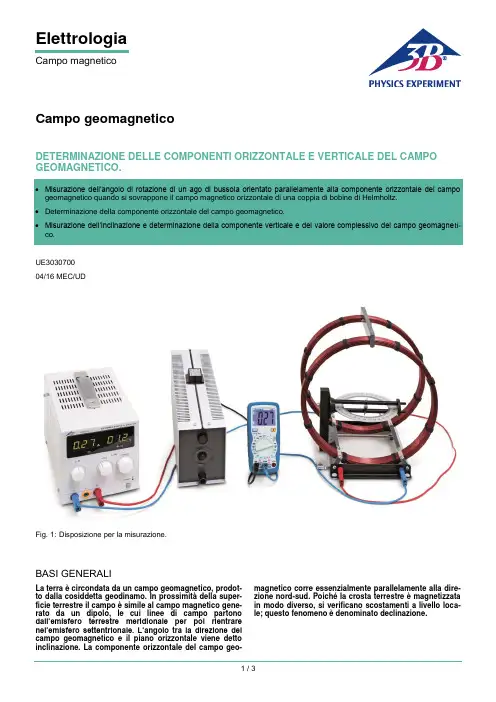
ElettrologiaCampo magneticoCampo geomagneticoDETERMINAZIONE DELLE COMPONENTI ORIZZONTALE E VERTICALE DEL CAMPO GEOMAGNETICO.UE3030700 04/16 MEC/UDFig. 1: Disposizione per la misurazione.BASI GENERALILa terra è circondata da un campo geomagnetico, prodot-to dalla cosiddetta geodinamo. In prossimità della super-ficie terrestre il campo è simile al campo magnetico gene-rato da un dipolo, le cui linee di campo partono dall’emisfero terrestre meridionale per poi rientrare nel’emisfero settentrionale. L’angolo tra la direzione del campo geomagnetico e il piano orizzontale viene detto inclinazione. La componente orizzontale del campo geo-magnetico corre essenzialmente parallelamente alla dire-zione nord-sud. Poiché la crosta terrestre è magnetizzata in modo diverso, si verificano scostamenti a livello loca-le; questo fenomeno è denominato declinazione.Fig. 2: Rappresentazione delle componenti dei campi magne-tici esaminati nell’esperimento e definizione del rel ativo angolo.Nell’esperimento vengono esaminati l’inclinazione e l’intensità, nonché la componente orizzontale e verticale del campo geomagnetico nel punto di misurazione. Si applica la correlazione (Fig. 2):(1) v h tan B B =⋅αα: InclinazioneB h : Componente orizzontale B v : Componente verticale e(2) B È pertanto sufficiente determinare le grandezze B h e α, per poter determinare anche le altre due.L’inclinazione α viene rilevata utilizzando un inclinatorio. Per determinare la componente orizzontale B h lo stesso inclinato-rio sull’orizzontale viene orientato in modo tale che l’ago di bussola integrato, che tende a disporsi parallelamente alla componente orizzontale, sia puntato sullo 0. Una coppia di bobine di Helmholtz genera un campo magnetico orizzontale supplementare B HH perpendicolare a B h determinando la rotazione dell’ago di un angolo β. Come da Fig. 2, vale(3)HHhtan B B =β Ai fini del miglioramento dell’accuratezza del dato, questa misurazione viene eseguita per diversi angoli β.ELENCO DEGLI STRUMENTI1 Bobine di Helmholtz da 300 mm 1000906 (U8481500) 1 Alimentatore CC 0-20 V, 0-5 A @230V 1003312 (U33020-230) o 1 Alimentatore CC0-20 V, 0-5 A @115V1003311 (U33020-115) 1 Multimetro digitale P1035 1002781 (U11806) 1 Inclinatorio E1006799 (U8495258) 1 Reostato a corsoio 100 Ω 1003066 (U17354) 1 Set di 15 cavi di sicurezza per esperimenti, 75 cm1002843 (U138021)MONTAGGIO E ESECUZIONENota:Preparare l'esperimento su una superficie orizzontale e piana posta in un luogo in cui la misurazione non sia soggetta a interferenze magnetiche ambientali.Determinazione della componente orizzontale B h ∙Per mezzo del volantino ruotare l'inclinatorio in modo tale che il piano del cerchio graduato e dell'ago della bussola sia parallelo alla superficie di appoggio.In questo modo l'ago della bussola si orienta sempre lungo la componente orizzontale del campo geomagnetico. ∙Ruotare l'inclinatorio sulla piastra di base in modo tale che le tacche 0° del cerchio graduato corrispondano alla direzione dell'ago della bussola.∙Spingere le bobine di Helmholtz sopra l'inclinatorio, fin-ché quest'ultimo non si trovi al centro fra le bobine (fig. 1) e l'asse delle bobine di Helmholtz non sia perpendicolare alla direzione dell'ago della bussola.∙ Collegare in serie le bobine di Helmholtz, il multimetro digita-le e il potenziometro scorrevole all'alimentatore (fig. 1). ∙ Regolare il potenziometro scorrevole su 100 Ω.∙Accendere l'alimentatore e aumentare la corrente, alzan-do la tensione tramite il regolatore fine di tensione conti-nua, finché la direzione dell'ago della bussola non corri-sponda alle tacche 5° del cerchio graduato. Annotare l'angolo di deviazione β = 5° nella tab. 1. Leggere sul multimetro il valore di corrente I e annotarlo nella tab. 1. ∙Aumentare progressivamente la corrente, in modo tale che l'angolo di deviazione si ingrandisca di 5° alla volta fino a raggiungere β = 75°. Annotare rispettivamente l'angolo di deviazione e il valore di corrente nella tab. 1. Quando il regolatore fine di tensione continua raggiunge la battuta, aumentare la corrente riducendo la resistenza mediante il potenziometro scorrevole.Determinazione dell’i nclinazione α ∙Per mezzo del volantino ruotare l'inclinatorio in modo tale che il piano del cerchio graduato e dell'ago della bussola sia parallelo alla superficie di appoggio.In questo modo l'ago della bussola si orienta sempre lungo la componente orizzontale del campo geomagnetico. ∙Ruotare l'inclinatorio sulla piastra di base in modo tale che le tacche 0° del cerchio graduato corrispondano alla direzione dell'ago della bussola.∙Mediante il volantino ruotare l'inclinatorio in modo tale che il piano del cerchio graduato e dell'ago della bussola sia perpendicolare alla superficie di appoggio. ∙ Attendere che l'ago della bussola si fermi.∙ Leggere l'angolo dell'inclinatorio α1 sul cerchio graduato dell'inclinatorio e annotarlo nella tab. 2.∙ Mediante il volantino ruotare l'inclinatorio di 180°. ∙ Attendere che l'ago della bussola si fermi.∙ Leggere l'angolo dell'inclinatorio α2 sul cerchio graduato dell'inclinatorio e annotarlo nella tab. 2.3B Scientific GmbH, Rudorffweg 8, 21031 Amburgo, Germania, ESEMPIO DI MISURAZIONE E ANALISITab. 1:I impostate e campimagnetici B HH delle bobine di Helmholtz calcolati in base all'equazione (5).Tab. 2: Inclinazione α determinata dalla media di entrambi ivalori misurati α1 e α2Determinazione della componente orizzontale B h Da (3) consegue che:(4) HH h tan B B =⋅βLa componente orizzontale B h corrisponde alla pendenza di una retta passante per l’origine ch e passa per i punti di misu-ra in un diagramma B HH – tan α.Il campo magnetico B HH della coppia di bobine di Helmholtz può essere determinato in modo semplice. All’interno di una coppia di bobine esso è fortemente omogeneo e proporziona-le all’intensità di co rrente I che attraversa una singola bobina:(5) HH B k I =⋅ con3274Vs 4105Am N k R -⎛⎫=⋅π⋅⋅ ⎪⎝⎭N = 124: Numero di spire R = 147,5 mm: Raggio ∙Calcolare il campo magnetico B HH della coppia di bobine di Helmholtz per tutte le correnti impostate I (tab. 1) in base alla formula (5) e annotare i risultati nella tab. 1.12345050100tan βB HH / T μFig. 3: Diagramma B HH – tan α per la determinazione dellacomponente orizzontale del campo geomagnetico∙ Riportare in un diagramma il campo magnetico B HH infunzione di tan β e unire i punti con una linea retta (fig. 2). ∙Determinare la componente orizzontale B h direttamente dall'incremento lineare. (6) h 23T B =μDeterminazione della componente verticale B dall'inclina-zione α ∙Determinare l'inclinazione α, facendo la media di entram-bi i valori misurati α1 e α2 (tab. 2) e annotare il valore ri-cavato nella tab. 2.∙Determinare la componente verticale in base alla formula (1).(7) v h tan 23T tan60,541T B B =⋅α=μ⋅︒=μDeterminazione del valore complessivo ∙Determinare il valore complessivo del campo magnetico B in base alla formula (2). (8) 47T B =μI valori ottenuti dalla misurazione della componente orizzonta-le e di quella verticale corrispondono in gran parte con i valori riportati in letteratura, riferiti all'Europa centrale B h = 20 μT e B = 44 μT.。
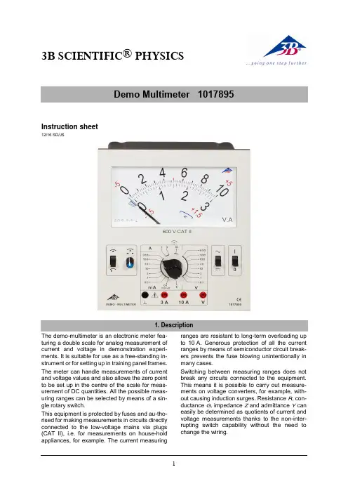
3B SCIENTIFIC ® PHYSICSInstruction sheet12/16 SD/JSThe demo-multimeter is an electronic meter fea-turing a double scale for analog measurement of current and voltage in demonstration experi-ments. It is suitable for use as a free-standing in-strument or for setting up in training panel frames. The meter can handle measurements of current and voltage values and also allows the zero point to be set up in the centre of the scale for meas-urement of DC quantities. All the possible meas-uring ranges can be selected by means of a sin-gle rotary switch.This equipment is protected by fuses and au-tho-rised for making measurements in circuits directly connected to the low-voltage mains via plugs (CAT II), i.e. for measurements on house-hold appliances, for example. The current measuringranges are resistant to long-term overloading up to 10 A. Generous protection of all the current ranges by means of semiconductor circuit break-ers prevents the fuse blowing unintentionally in many cases.Switching between measuring ranges does not break any circuits connected to the equipment. This means it is possible to carry out measure-ments on voltage converters, for example, with-out causing induction surges. Resistance R , con-ductance G, impedance Z and admittance Ycan easily be determined as quotients of current and voltage measurements thanks to the non-inter-rupting switch capability without the need to change the wiring.The demo multimeter conforms to safety regula-tions for electrical measurement, control and la-boratory equipment, as specified in DIN EN 61010-1, protection class 2 and to measuring ca-tegory CAT II for up to 600 V. The nominal volt-age between the phase conductors and the neu-tral for voltage and current measurements (in cir-cuits directly connected to mains electricity) must not exceed 600 V in order to conform to CAT II. The meter is intended for measurements within its measuring ranges and in a measuring environ-ment as described in detail in the course of this manual. Safe operation of the multimeter is gua-ranteed if it is solely used as specified. Safety can-not be guaranteed, however, if the multimeter is used incorrectly or handled without due care and attention. In order to avoid serious injury due to current or voltage shocks, the following safety in-structions are to be observed at all times.The multimeter may only be used by persons who are able to recognise the risks of contact and take due precautions to avoid them. Voltages in ex-cess of 33 V AC (RMS) or 70 V DC are to be re-garded as actively dangerous if the current, charge or energy stored should exceed certain values (see DIN EN 61010-1).∙Carefully read the instruction manual before using the multimeter and obey the instruc-tions therein.∙The multimeter may only be used in a dry, dust-free environment with no risk of explo-sions occurring.The assumption needs to be made that unfore-seen voltages may be present in the vincinity of objects being measured (e.g. faulty equipment). ∙Before using the multimeter, check the hou-sing and measuring leads for damage and if there should be any malfunctions or visible damage, the multimeter is not to be used.Pay specific attention to the insulation for the measuring sockets.∙The multimeter may not be used to make measurement on circuits which exhibit co-rona discharge (high voltage).∙Particular care is to be taken when making measurements on high-frequency circuits where dangerous voltages may arise due to superimposition of components.∙The authorised measuring range is not to be exceeded. If measurements are made when the magnitude of the variable is unknown, al-ways select a large measuring range before shifting down to lower ones. ∙Make very sure that the voltage value be-tween the measured contact and earth or be-tween the ground socket and the measure-ment socket does not exceed 600 V.∙Before using the analogue multimeter to check that a voltage source is not exhibiting any actual voltage, check that the meter is working properly by selecting the battery test function.∙When measuring current, make sure the electricity is turned off before the analogue multimeter is connected into the circuit.∙When making measurements, always con-nect the ground lead first. Disconnect the sig-nal measurement lead before unplugging the ground.∙Turn off the multimeter before opening the casing, disconnect the power to the circuit and the measuring leads from the multimeter. If measurements are made where there are any risks of coming into contact with electricity, a sec-ond person is to be informed.∙The demo-multimeter should not be stored, set up or operated within reach of children. ∙When the multimeter is used by teenagers, trainees etc., a suitable person should super-vise to ensure the equipment is used safely. ∙If measurements are to be made where volt-ages exceed 33 V AC (RMS) or 70 V DC, be especially careful and only use safety experi-ment leads.Measuring categories according to DIN EN 61010-1.CAT I or unstipulated: Approved for measure-ments in circuits which are not directly connected to the low voltage mains grid (e.g. batteries). CAT II: Approved for measurements in circuits which are directly connected, by a mains lead and plug for instance, to the low voltage mains grid (e.g. household or office appliance and lab equipment).CAT III: Approved for measurements in circuits which are part of a building’s wiring installation (e.g. stationary consumers, distribution terminals, appliances connected directly to the distribution box).CAT IV: Approved for measurements in circuits which are directly connected to the source of the low voltage mains (e.g. electricity meters, main service feed, primary excess voltage protection).Scales: 0 … 10, linear0 … 3, linearScale length: 160 mmPointer deflection: 0…90°Electricalzero-point offset: in all DC rangesMeasurements:Voltage ranges: 0.1/ 0.3/ 1/ 3/ 10/ 30/100/ 300/ 600 V AC/DC Current ranges: 0.1/ 0.3/ 1/ 3/ 10/ 30/100/ 300 mA AC/DC1/ 3/ 10 A AC/DCInput resistance: 1 MΩ AC/DCVoltage drop whenmeasuring current: 100 mV approx. AC/DCReference conditions:Ambient temperature: 23 °COperating alignment: VerticalSignal form: Sine (1% max. discrep-ancy)Peak factor:Frequency range: 40 Hz … 50 Hz … 5 kHzAccuracy (at reference conditions):DC quantities: Class 2DC withzero-point offset: Class 5AC quantities: Class 3Extended frequency range (class 10):3 – 600 V: 40 Hz … 50 Hz … 40 kHz0,3 – 1 V: 40 Hz … 50 Hz … 10 kHz0,3 – 3000 mA: 40 Hz … 50 Hz … 40 kHz10 A: 40 Hz … 50 Hz … 40 kHz Resistance, conductance, impedance, admit-tanceThese quantities can be determined by forming various quotients involving “simultaneous meas-urements” of current and voltage.R = U / I: below 1 mΩ … above 10 MΩS = I / U: below 1 µS … above 30 SZ = U / I: below 1 mΩ … above 10 MΩ,40 Hz … 40 kHzY = I / U: below 1 µS … above 30 S,40 Hz … 40 kHz Voltage ranges: 600 V long-term in allvoltage ranges Current ranges: 10 A of long-term load-ing in 3-A and 10-ArangesElectrical safety:Safety specifications: EN 61010-1 Measuring category: CAT II: 600 V Contamination level: 2Protection type: IP20Connectors: 4-mm safety socketsProtection:Fuses: 2x FF 10 A/600 V(10 x 38 mm) Breaking capacity: at least 10 kA3B order number: 5008564Power supply:Battery: 1x 1.5 V, AA IEC LR6 Automatic cut-off after: 45 min ± 10 minElectromagnetic compatibility: Interference emission: EN 55011:2009 Interference resistance: EN 61326-1:2013Operating conditions:Ambient temperature: 5 °C ... 23 °C … 40°C Storage temperature: -20 … 70°CRelative humidity: <85% with no conden-sationGeneral data:Shock test: max. 147 m/s² Height: 297 mm Dimensions: 259 x 297 x 125 mm3 Weight: 1,7 kg approx.1 Display2 Slotted screw for zero calibration 3Toggle switch 1Zero point centre / left4 Calibration trimmer for settingcentre zero point5 Rotary switch to select the mea-surement range6 Ground socket7 Current measurement socket forup to 3 A8 Current measurement socket forup to 10 A9 Voltage measurement socket 10 Toggle switch 2AC / DC voltage measurements 11 Power switch4.2 Rear12 Cover plate for battery andfuses13 Rating plate 14 Fuse diagram 15 Lower edge 16 FeetDisplayFrontRearEarth symbol∙ Set up the demo multimeter vertically.∙ Do not connect measuring leads to begin with.∙ ∙The needle will point to the zero point of the scale on the left. If it does not, the amount of charge of the battery should be checked.7.1 To switch on:∙7.2 Checking battery charge: ∙ Turn on the demo-multimeter. ∙ Disconnect all measuring leads.∙ Set the toggle switch 2 to .∙Set the rotary switch to.If the battery is sufficiently charged, the needle to the following range indication,If this is not the case, the battery will7.3 Zero point calibration:∙ Turn on the demo-multimeter. ∙ Turn the rotary switch to 600 V.∙ Connect the common/ground socket and thevoltage measurement socket together by means of a short connecting lead.∙ Turn the zero-point trimmer screw to adjustthe zero point as needed.7.4 Zero point calibration for centre zeropoint:For measurements of DC current and voltage, the zero point of the scale can be moved to the centre of the dial. For this purpose the scales are la-belled with red numbers..∙ Turn on the demo-multimeter. ∙ Disconnect all measuring leads.∙ Set the toggle switch 2 to . ∙ ∙Use the zero-point trimmer to line up the nee-dle precisely in the centre of the dial (red di-vision).7.5 To switch off:∙ Set the power switch to .∙Set the four-way switch to .When the meter is turned off, the needle points to.7.6 If a measurement is interrupted by batterycut-out:After 45 minutes of use, the multimeter is auto-matically shut off and the needle will then point to. To switch back on:∙ Set the power switch of the multimeter to offand then use it to turn the meter back on.∙If measurements are made when the magni-tude of the variable is unknown, always selecta large measuring range before shifting downto lower ones.∙Connect the terminal at the lower potential to the common/ground socket.∙Connect the common/ground lead first and only then the signal lead.8.1 DC currents up to 3 A:∙Set the toggle switch 2 to .∙Alternatively, if measurements are to be∙Select the required current measuring range to a range measured in mA or A.8.2 AC currents up to 3 A:∙∙Select the required current measuring range to a range measured in mA or A.∙Set up a measuring range of 10 A.∙Connect the terminal at the lower potential to the common/ground socket.∙Connect the common/ground lead first and only then the signal lead.9.1 DC currents up to 10 A:∙Set the toggle switch 2 to .∙Alternatively, if measurements are to be9.2 AC currents up to 10 A:∙∙If measurements are made when the magni-tude of the variable is unknown, always select a large measuring range before shifting down to lower ones.∙Connect the common/ground lead first and only then the signal lead.10.1 DC voltages up to 600 V:∙ Set the toggle switch 2 to .∙Alternatively, if measurements are to be∙ Select the required measuring range to a range measured in V.∙For measurements of voltage up to 100 mV, set the rotary switch to the range 0.1 mA/100 mV.10.2 AC voltages up to 600 V:∙∙ Select the required measuring range to a range measured in V.∙For measurements of voltage up to 100 mV, set the rotary switch to the range 0.1 mA/100 mV.11.1 DC voltages and currents:∙ Set the toggle switch 2 to .∙Use the rotary switch to set the desired volt-age measuring range and read off the meas-urement.∙Set a suitable current measuring range and read off the measurement.11.2 AC voltages and currents:∙∙Use the rotary switch to set the desired volt-age measuring range and read off the meas-urement.∙Set a suitable current measuring range and read off the measurement.The demo-multimeter has a compartment which houses both the battery and fuses and which is accessible at the rear once its cover is opened. One fuse each is provided for the 3 A and 10 A sockets:FF10 A/600 V, breaking capacity: at least 10 kA (3B order number: 5008564)The polarity is indicated by plus and minus signs inside the fuse holder compartment. A mechani-cal system ensures the battery makes no contact if it is inserted the wrong way round.Battery and fuse compartment12.1 Battery testing:Batteries which are discharged and have not been used for a while may leak.12.2 Changing the battery:∙Remove the cover at the rear.∙Replace flat batteries with 1.5-V alkaline bat-teries of size AA IEC LR6.∙Place the negative pole of the battery on thespring.∙Close the cover again afterwards.12.3 Changing fuses:∙Remove the cover at the rear.∙Check the fuses.∙Blown fuses should be replaced with ones ofthe same rating.∙Close the cover again afterwards.∙For cleaning, use a soft cloth, slightly mois-tened with alcohol, or a brush.Electrostatic charging of the display window canaffect the measurements under certain circum-stances:∙To remove such charge, use a soft clothslightly soaked in alcohol or a paint brush.Dirt or moisture in the measurement sockets canaffect readings.∙Shake out any dirt that may be in the meas-urement sockets.∙Soak a new swab with isopropyl alcohol andwork around the inside of each measurementsocket.∙The packaging should be disposed of at localrecycling points.Should you need to dis-pose of the equipment it-self, never throw it away innormal domestic waste. Ifbeing used in privatehouseholds it can be dis-posed of at the local publicwaste disposal authority.∙Comply with the applicable regulations for thedisposal of electrical equipment.∙Do not dispose of the batteries in the regularhousehold garbage. Follow the applicable le-gal regulations (UK: Waste Batteries and Ac-cumulators Regulations, EU: 2006/66/EC).3B Scientific GmbH ▪ Rudorffweg 8 ▪ 21031 Hamburg ▪ Germany ▪ 。

测试仪表GY-315钳形接地电阻测试仪说明书一、引言欢迎使用AAXX科技有限公司的高质量专业测试仪表GY-315钳形接地电阻测试仪,该仪表是基于我们多年接地电阻和电气安装测试设备的生产和开发经验设计并制造。
GY-315是一种便携式、电池供电的专业接地电阻测试仪。
仪表配备有测试所必需的附件。
操作简单、直观,操作者只需要阅读说明书而不必参加专门的培训就能够操作。
二、概述GY-315钳形接地电阻测试仪适用于电信、电力、气象、机房、电力配电线路、铁塔输电线路、加油站、工厂接地网、避雷针等。
随着我国城市化发展,使得用传统的打地桩方法测量,接地电阻越来越困难。
主要是接地体周围找不到土壤,它们全部被水泥覆盖,即使有街心花园,但它们的土壤也往往与大地的土壤分开,更何况传统方法打辅助电极时对辅助电极的相对位置有要求,要找到满足此要求的土壤,在许多情况下是更加困难。
该仪表具备了无辅助地极测量的独特功能,改变了测试接地电阻传统的测量原理和手段:采用二电极测量原理和利用钳口测量技术无需打辅助地极,也无需将接地体与负载隔离,实现了在线测量。
三、主要技术指标1、接地电阻测量范围:0.1Ω~1000Ω2、显示屏:4位LCD数字显示3、钳口尺寸:Ø50mm最小分辨率为0.01Ω4、工作湿度:10%~90% 工作温度:0ºC~+50°C5、电源:4节5号1800mAH镍氢充电电池6、重量:0.8KG(含电池)7、尺寸:230MM×120MM×42MM8、保护等级:双重绝缘9、量程及精度:测量范围(Ω)分辨力(Ω)精确度(Ω)0.1~0.99 0.01 ±(1%+0.01Ω)1.0~49.9 0.1 ±(1.5%+0.1Ω)50.0~99.5 0.5 ±(2%+0.5Ω)100~199 1 ±(3%+1Ω)200~395 5 ±(6%+5Ω)400~590 10 ±(10%+10Ω)600~1000 20 ±(20%+20Ω) 四、结构A:液晶显示屏B:主机C:按键板D:发射钳、接收钳两组插孔E:发射钳F:接收钳五、按键功能本机按键采用一体化键盘设计,共设四个按键,如下图:“电源开按钮”具有开机功能,同时进入测试状态。
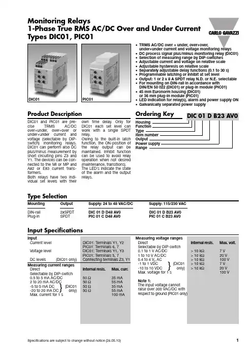
Monitoring RelaysProduct Description•TRMS AC/DC over + under, over+over,under+under current and voltage monitoring relays•DC process signal plus/minus monitoring relay (DIC01) •Selection of measuring range by DIP-switches •Adjustable current and voltage on relative scale •Adjustable hysteresis on relative scale•Separately adjustable delay functions (0.1 to 30 s)•Programmable latching or inhibit at set level•Output: 1 or 2 x 8 A SPDT relay N.D. or N.E. selectable •For mounting on DIN-rail in accordance with DIN/EN 50 022 (DIC01) or plug-in module (PIC01)•45 mm Euronorm housing (DIC01) or 36 mm plug-in module (PIC01)•LED indication for relay(s), alarm and power supply ON •Galvanically separated power supplyType Selection1-Phase True RMS AC/DC Over and Under Current Types DIC01, PIC01Input SpecificationsD C01 and P C01 are pre-cise TRMS AC/DC over+under, over+over or under+under current and voltage (selectable by D P-switch) monitoring relays.DI C01 can perform also DC plus/minus measurement by short circuiting pins Z3 and Y1. The devices can be con-nected to the MI or MP and A82 or E83 current trans-formers.Both relays have two indi-vidual set levels with theirown time delay. Only for D I C01 each set level can work with a single SPDT relay.Owing to the built-in latch function, the ON-position of the relay output can be maintained. I nhibit function can be used to avoid relay operation when not desired (maintenance, transitions).The LED's indicate the state of the alarm and the output relays.Measuring voltage ranges DirectInternal resis.Max. volt.Selectable by DIP-switch 0.1 to 1 V AC/DC >10 k Ω7V 1to 10 V AC/DC >10 k Ω20 V 0.4 to 4 V p AC> 10 k Ω100 V -1 to 1 VDC(DIC01>10 k Ω7V -10 to 10 VDC only)> 10 k Ω20 V Max. voltage for 1 s100 VNote 1:The input voltage cannot raise over 300 VAC/DC with respect to ground (PIC01 only)DIC01PIC01Mounting Output Supply: 24 to 48 VAC/DC Supply: 115/230 VAC DIN-rail 2xSPDT DIC 01 D D48 AV0 DIC 01 D B23 AV0Plug-inSPDTPIC 01 C D48 AV0 PIC 01 C B23 AV0}DIC01, PIC01General SpecificationsDIC01, PIC01Mode of OperationD I C01 and P I C01 monitor both AC and DC current and voltage. D I C01 can also monitor positive and nega-tive DC voltage connecting terminals Y1 and Z3. Example 1(no contact input -under+over voltage - 2 x SPDT N.D. relays (1 x SPDT for PIC01) - TRMS)DIC01: One relay operates when the voltage drops below the under voltage set point for more than the respective delay time. I t releases when the voltage exceeds the set level plus the set hysteresis. The other relay operates when the voltage exceeds the over voltage set point for more than the respective delay time. I t releases when the voltage drops below the set level minus hysteresis.PIC01:The relay operates when the voltage drops below the under voltage set level for more than the respective set delay time or when it exceeds the over voltage set level for more than the relative set delay time. The relay releases when the voltage exceeds the under voltage set level plus hysteresis and it drops below the over voltage setlevel minus hysteresis (thehysteresis is the same forboth set levels).Example 2(latch enable active -under+under current - 2 xSPDT relays (1 x SPDT forPIC01) - TRMS)DIC01:Each relay operatesand latches when the cur-rent drops below the respec-tive set level for more thanthe respective delay time.Provided that the currenthas exceeded the respectiveset level plus hysteresis,each relay releases when thecontact input’s connection isinterrupted.PIC01:The relay operateswhen the current dropsbelow the higher set level formore than the respectivedelay time. Provided that thecurrent has exceeded thehigher set level plus hystere-sis the relay releases whenthe contact input’s connec-tions is interrupted.NoteDifferent delay times can beused for appropriate reac-tion according to the setpoints.Example 3(inhibit enable active -over+over current with M ICT-DPDT relay (SPDT forPIC01) - TRMS)Provided that the contactinput’s connection is inter-rupted, the relay operateswhen the current flowing inthe MI CT exceeds the lowerset level for more than therespective delay time. I treleases when the currentdrops below the lower setlevel minus hysteresis orwhen the contact input’spins are connected.Example 4(inhibit enable active -over+over current with A82-10 CT - DPDT relay (1 xSPDT for PIC01) - TRMSProvided that the contactinput’s connection is inter-rupted, the relay operateswhen the current flowing inthe A82-10 CT exceeds thelower set level for more thanits delay time. I t releaseswhen the current dropsbelow the lower set levelminus hysteresis or whenthe contact input’s pins areconnected.Example 5 (DIC01 only)(no contact input -under+over voltage - 2 xSPDT N.D. relays -plus/minus DCOne relay operates when thevoltage drops below theunder voltage set point formore than the respectivedelay time. I t releases whenthe voltage exceeds the setlevel plus the set hysteresis.The other relay operateswhen the voltage exceedsthe over voltage set point formore than the respectivedelay time. I t releases whenthe voltage drops below theset level minus hysteresis.n this case the spare frontlabel has to be placed onthe device for proper leveladjustment.NoteWhen the inhibit contact isopened, if the input signal isalready in alarm position, thedelay time needs to elapsebefore relay(s) activation.Operation DiagramsDIC01, PIC01Over+over voltage/current - N.D. relay(s)Over+over voltage/current - Latch - N.D. relay(s)Function/Range/Level and Time Delay SettingAdjust the input range set-ting the DI P switches 1 and 2of the main black selector as shown below.Select the desired function setting the DIP switches 3 to 6of the black selector and 1, 2 of the small red selector Selection of level, time delay and hysteresis:Upper knob:Setting of hysteresis on rela-tive scale: 0 to 30% on set value.Centre knobs:Current level setting on rela-tive scale: 10 to 110% on full scale.Lower knobs:Setting of delay on alarm time on absolute scale (0.1to 30 s).Wiring DiagramsOperation Diagrams (cont.)Over+under voltage/current - N.E. relay(s)Under+under voltage/current - N.D. relay(s)Over+under voltage/current - Inhibit - N.E. relay(s)DIC01, PIC01DimensionsWiring Diagrams (cont.)。

CM-IWM.10Insulation monitoring relayThe insulation monitor CM-IWM.10 provides best and up to date insulation monitoring of modern IT systems in an optimum and state of the art way fulfilling the relevant standards. The device can be used in the most flexible way for AC, DC and AC/DC systems even with large leakage capacity to earth (PE). The adjustment of the setting values is simple and user friendly done on 2 rotaryswitches on the front of the device. Via LEDs the measured value, device parameters and device status are indicated easy to read.Benefits–Preventive fire and system protection–Quick fault localisation through selective earth fault detection to L+ and L- –Universal application in non-earthed DC / AC and mixed IT networks with maximal up to 1000 V measurement voltage–Suitable for large earth leakage capacitances up to 1000 μF–Simplest setting via engaging rotary switches–For monitoring photovoltaic system, also with thin-film technology–Optimised measuring times – normally shorter than with known methods–Monitoring also with voltage-free mains –Measuring circuit with broken wire detection –No additional coupling device requiredOrder dataCharacteristics–Insulation monitoring according to IEC/EN 61557-8–Detection of symmetric and asymmetric insulation faults – 1 c/o contact each for prewarning and warning –Prewarning threshold setting range: 20 kΩ ... 2 MΩ –Warning threshold setting range: 1 kΩ ... 250 kΩ –Open- or closed-circuit principle configurable–Setting the maximum earth leakage capacitance toshorten the response time–Simple, clearly arranged adjustment of the device withscrewdriver–LED chain to indicate the current insulation resistance –Display of active measuring circuits –Automatic and manual device self-test –Alarm storage selectable–External test and reset pushbutton can be connected –Width 90 mm–Various certifications and approvals (see overview,document no. 2CDC112250D0201)2C D C 251 002 S 0016Application / monitoring functionInsulation monitoring of:–Non-earthed DC / AC and mixed IT networks–UPS systems–Networks with frequency inverters–Battery networks–Networks with direct current drives–Photovoltaic systems–Hybrid and battery-powered vehiclesThe CM-IWM serves to monitor insulation resistance in accordance with IEC/EN 61557-8 in unearthed IT AC systems, IT AC systems with galvanically connected DC circuits, or unearthed IT DC systems.The insulation resistance between system lines and system earth is measured. If this falls below the adjustable threshold values, the output relays switch into the fault state.When applying control supply voltage the green LED …PWR“ turns on and an internal selftest of 10 s starts, where the LEDs of the indicator string light up in sequence. After this, measurement of the insulation resistance in the measuring circuit begins.Insulation measurement between terminals L(+) / L(-) and PE / KETerminals L(+) and L(-) are connected to the mains to be monitored. Broken wire detection, constantly effective during operation, generates an error messages if both terminals are not connected with low resistance through the mains.In addition, the two terminals PE and KE must be connected to the protective conductor system via separate lines. An error message is given here as well if a line is interrupted (see section …Actions in case of connection faults“).If the main measuring circuit is activated, an active measuring voltage with alternating polarity is applied between L(+) / L(-) and PE / KE to measure the insulation resistance. During the measuring phase with positive polarity, the "Active" LED flashes with a long ON-phase and with negative polarity with a short ON-phase.The length of the positive and negative measuring phases depends on the settings on the rotary switch "CE/μF", the actual leakage capacitance of the monitored network and with DC networks, on the level and duration of possible mains voltage fluctuations. Correct and preferably quick measurement is thus given with different mains conditions. In the event of particularly adverse conditions and major interferences, the measuring analysis can be steadied and delayed in addition with rotary switch "tv" if necessary.The current insulation resistance is determined and analysed at the end of each measuring phase. The LE D-chain shows the resistance determined, and the output relays for prewarning "VW" and alarm "AL" switch according to the respective response values set. If the response thresholds have been undercut, the LEDs "VW" or "AL" light according to the insulation fault location: "+", "-" or "+" and "-" simultaneously for AC faults or symmetric insulation faults.Storing insulation fault messageIf terminal R is open, the insulation fault messages (relay, LEDs) are stored when the respective response value is undercut, but also when the insulation resistance returns to the OK-range. In addition, the temporary minimum values of the insulation resistance are indicated on the LED chain through dimmed LEDs.If the "Reset" button on the device front is pressed or terminal R is connected with G, the stored insulation fault messages are reset when the insulation resistance is again in the OK-range.Output relay for insulation fault messagesThe rotary switch "CE/μF Rel." allows selecting the open circuit (A) or closed circuit (R) operation for the output relays "AL"(contacts 11-12-14) and "VW" (contacts 21-22-24).With the open circuit operation, the relays respond when the response values are undercut, with the closed circuit operation they release when the response values are undercut.If 2 different response values are not needed, "VW" and "AL" can be set to the same value. The output relays switch together in this case.2 - CM-IWM.10 | Data sheetBroken wire detectionAs mentioned above, all terminals of the measuring circuit are constantly monitored for wire breaks - not only at Power-On ora manual or occasional automatic test. The response time of monitoring is only a few seconds.Broken wire detection between L(+) and L(-) is performed via coupled alternating voltage. This alternating voltage is short-circuited if the terminals are connected to the connected mains at low-resistance. The device detects that the mains to be monitored is properly connected. Since this broken wire detection is carried out with alternating voltage, large earth leakage capacitances should be avoided between L(+) and L(-), since the capacitive reactance of these capacitances also short-circuits this alternating voltage. The device would no longer detect a connection fault on L(+)/L(-). Especially parallel lines should be prevented over larger distances.Device test functionsPrincipally, 2 different test functions are implemented: The "self-test" and the "expanded test":The self-test of the device is performed automatically after Power-On and every 4 operating hours. It can also be triggered manually at any time by pressing the "Test" button at the device front or with an external pushbutton connected between terminals T and G.With the self-test, contrary to the expanded test, the status of the output relays is not affected; the sequence is as follows. Switching to the negative measuring phase is performed for 4 s. The "Active" LED flashes Y and the LEDs of the LED-chain are selected in sequence and the internal circuit is checked. After this, switching to the positive measuring phase is performed for 4 s. The "Active" LED flashes Z and the LED-chain cycles again and additional internal tests are performed. Insulation measurement continues normally after a pause of 2 s if no faults have occurred.The expanded test is started when the internal or external "Test" button is pressed (or is still held) at the end of the 8 sec self-test, described above. The sequence is the same as with the self-test (2 measuring phases at 4 s + 2 s pause); however, the output relays "AL" and "VW" as well as the associated LEDs switch to the alarm state.If the Reset button is pressed during the 8 s or terminals R-G are connected, the expanded test is terminated after these 8 sec. Otherwise, the phases of the expanded test are constantly repeated, and, in addition, the "ERR" LED is on. However, the expanded test is terminated as soon as the Reset button is pressed. The device switches to the OK-state and restarts insulation measurement.Behaviour with internal device faultsIf internal device faults were detected during the test function, the LE D …E RR“ is lightening and the measuring circuit is deactivated internally. The LED …Active“ turns off. The output relays …AL“ and …VW“ as well as the corresponding LEDs switchto the alarm state and all LEDs of the LED chain turn off.Behaviour with connection faultsMeasurement is suspended if a line interruption is detected at terminals L(+) / L(-); the LED …Active“ turns off. This broken wire detection is signalled by flashing S of the LED …ERR“. The output relays …AL“ and …VW“ as well as the corresponding LEDs go into alarm state and all LEDs of the indicator LED chain turn off.Measurement of the connection insulation resistance restarts after the connection interruption has been corrected. However, stored alarm messages are preserved.If the connections PE/KE to the protective conductor system are interrupted, the same responses take place as with an interruption at terminals L(+)/L(-), only that the LED …ERR“ flashes differently: U.Data sheet| CM-IWM.10 - 3Function diagram4 - CM-IWM.10 | Data sheetElectrical connectionConnection examplesData sheet| CM-IWM.10 - 5Operating state indicationLEDs, status information and fault messagesPWR:green LED V control supply voltage appliedERR:V internal device errorred LEDS connection error L+/L-U connection error PE/KE Active:Z measuring phase with positive polarity green LEDY measuring phase with negative polarity LED chain:yellow LED V8 LEDs indicate the current insulating resistance (m 10 k q ... M 2 M q)VW +:lower than prewarning value to + potential yellow LED V R EVW -:lower than prewarning value to - potential yellow LED V R EVW + and VW -:yellow LED V AC fault / symmetric faultAL +:lower than warning value to + potential red LED V R EAL -:lower than warning value to - potential red LED V R EAL + and AL -:red LED V AC fault / symmetric fault6 - CM-IWM.10 | Data sheetData sheet | CM-IWM.10 - 7Safety instructionsWarning!Risk of electrocution!Danger to life or risk of serious injuries• Disconnect the system and device from the power supply and ensure they remain disconnected during electrical installation.• The voltage of the monitored voltage system is connected to terminals L(+) / L(-). Please observe sufficient distance to terminals of neighbour devices and to the grounded metal cabinet or box (min. 0.5 cm).• The terminals of the control inputs T, R and G have no galvanic separation to the measuring circuit L(+) and L(-) and are electrically connected together, therefore they have to be controlled by volt free contacts or bridge. These contacts or bridges must provide a sufficient separation depending on the mains voltage on L(+)-L(-).• No external potentials may be connected to control terminals T and R. The associated reference potential is G (identical with PE), and the connection of the terminals is made via bridges to G.Attention!• Before checking insulation and voltage, disconnect the monitoring device from the power source!• Only one insulation monitor may be active in a network to be monitored, since the devices wouldotherwise influence each other. When coupling several networks or incoming feed sections, where each of them is equipped with its own insulation monitor, all of them must be deactivated except for one insulation monitor.• Device terminals PE and KE must always be connected via separate lines to different terminal points of the protective-conductor system.• The device must not be operated without KE/PE connection!• The measuring circuit should not be connected via longer parallel guided wires, as this may interfere with the broken wire detection. Also large capacities between L(+) und L(-) have to be avoided.Important!• The measuring circuit can be connected with its terminals L(+) and L(-) both to the DC and also AC side of a mixed network; it is done most practically where the primary incoming power supply takes place. Selector switch "t v / U N " should be set accordingly.For photovoltaic systems and hybrid vehicles, the measuring circuit of the CM-IWM is connected on the DC side; the auxiliary measuring circuit can then be used to monitor the (deactivated) AC side.• If a monitored AC system includes galvanically connected DC circuits (e.g. via a rectifier), an insulation failure on the DC side can only be detected correctly, when a current of min 10 mA can flow via the semiconductor connections.• If a monitored DC system includes galvanically connected AC circuits (e.g. via an inverter), an insulation failure on the AC side can only be detected correctly, when a current of min 10 mA can flow via the semiconductor connections.• The measuring circuit is designed for large leakage capacitances up to 1000 μF. The selection switch "CE/μF" must be set accordingly. Measurement of the insulation resistances is not falsified by this; however, longer periods are required for the measuring phases than with small capacitances. If the maximum approximate leakage capacitance is known, the selector switch "CE/μF" can possibly be set to smaller values, which reduces the response time further.• For the main measuring circuit, the nominal voltage range for DC is specified with 690 V; however, absolute values up to max. DC 1000 V are permissible.• This is a Class A product. In a domestic environment this product may cause radio interference in which case the user may be required to take adequate measures.• This device is designed for IT systems with symmetric system leakage capacitances. With highlyunsymmetrical leakage capacitances, the device may not work the way it was intended.Technical dataData at Ta = 25 °C and rated values, unless otherwise indicatedInput circuitRated control supply voltage U S24 V DCVoltage range20-30 V DCTypical power consumption max. 5 WMeasuring ciruitControl inputbetween T, R and G Current flow approx. 3 mANo-load voltage to ground approx. 12 VPermissible wire length< 50 mMin. activation time0.5 sOutputContacts 2 x 1 c/o contacts for VW and ALThermal current I th 4 ASwitching capacity to AC-15n/o contact 3 A / AC 230 V acc. to IEC/EN 60947-5-1n/c contact 1 A / AC 230 V acc. to IEC/EN 60947-5-1 Electrical life at 8 A, AC 250 V 1 x 10⁴ switching cyclesShort circuit strength max. fuse rating 4 A gL acc. to IEC/EN 60947-5-1Mechanical life10 x 106 switching cyclesGeneral DataOperating mode Continuous operationTemperature range operation- 25 ... + 60 °Cstorage- 40 ... + 70 °C Relative air humidity93 % at 40 °CAtmospheric pressure860-1600 mbar (86-106 kPa)Altitude IEC/EN 60664-1< 4000 m8 - CM-IWM.10 | Data sheetClearance andcreepage distancesRated impulse voltage / pollution degree IEC/EN 60664-1Measuring ciruit L(+) / L(-) to auxiliary voltage DC and relay contacts VW, AL8 kV / 2 auxiliary voltage DC to relay contacts VW, AL8 kV / 2 relay contacts VW to relay contact AL 4 kV / 2Insulation test voltage, routine test AC 5 kV; 1 sAC 2.5 kV; 1 sTechnical dataEMCElectrostatic discharge (ESD)IEC/EN 61000-4-28 kV (air)HF irradiation IEC/EN 61000-4-380 MHz-2.7 GHz: 10 V/mFast transients IEC/EN 61000-4-4 4 kVSurge voltages IEC/EN 61000-4-5betweenA1 - A2: 1 kVL(+) - L(-): 2 kVA1, A2 - PE: 4 kVL(+), L(-) - PE: 4 kVcontrol line: 0.5 kVcontrol line and earth: 1 kVHF-wire guided IEC/EN 61000-4-610 VInterference suppression EN 55011Limit value class AWhen connected to a low voltage public system (Class B,EN 55011) radio interference can be generated. To avoidthis, appropriate measures have to be takenDegree of protectionHousing IEC/EN 60529IP 40Terminals IEC/EN 60529IP 20Housing Thermpolastic with V0 behaviour according to UL subject 94 Vibration resistance IEC/EN 60068-2-610-55 Hz: 0.35 mm2-13.2 Hz: ± 1 mm13.2-100 Hz: ± 7 gShock resistance IEC/EN 60068-2-2710 g / 11 ms, 3 pulsesClimate resistance IEC/EN 60068-125 / 060 / 04Terminal designation EN 50005Connecting capacity 1 x 4 mm2 solid1 x 2.5 mm2 stranded ferruled (isolated)2 x 1.5 mm2 stranded ferruled (isolated)DIN 46228-1/-2/-3-42 x 2.5 mm2 stranded ferruled (isolated)DIN 46228-1/-2/-3Stripping length8 mmTightening torque0.8 NmWire fixing Plus-minus terminal scews M3,5 terminal with wireprotectionMounting IEC/EN 60715DIN railWeight approx. 500 gDimensions Width x height x depth90 x 90 x 121 mmData sheet| CM-IWM.10 - 9Measuring times10 - CM-IWM.10 | Data sheetABB STOTZ-KONTAKT GmbHP. O. Box 10 16 8069006 Heidelberg, Germany Phone: +49 (0) 6221 7 01-0Fax: +49 (0) 6221 7 01-13 25E-mail:*****************.comYou can find the address of your local sales organisation on theABB home page/contacts-> Low Voltage Products and Systems Contact usNote:We reserve the right to make technical changes or modify the contents of this document without prior notice. With regard to purchase orders, the agreed particulars shall prevail. ABB AG does not accept any responsibility whatsoever for potential errors or possible lack of information in this document.We reserve all rights in this document and in the subject matter and illustrations contained therein. Any reproduction, disclosure to third parties or utilization of its contents – in wholeor in parts – is forbidden without prior written consent of ABB AG.Copyright© 2018 ABBAll rights reserved D o c u m e n t n u m b e r 2 C D C 1 1 2 2 4 2 D 0 2 0 1 R e v . B ( 0 6 . 2 0 1 8 )。
尊敬的顾客感谢您购买本公司大电流发生器。
在初次使用该仪器前,请您详细地阅读本使用说明书,将可帮助您安全熟练使用该仪器。
我们的宗旨是不断地改进和完善公司的产品,因此您所使用的仪器可能与使用说明书有少许差别。
若有改动,我们不一定能通知到您,敬请谅解!如有疑问,请与公司售后服务部联络,我们定会满足您的要求!由于输入输出端子、测试柱等均有可能带电压,您在插拔测试线、电源插座时,会产生电火花,小心电击,避免触电危险,注意人身安全!◆慎重保证本公司生产的产品,在发货之日起三个月内,如产品出现缺陷,实行包换。
一年(包括一年)内如产品出现缺陷,实行免费维修。
一年以上如产品出现缺陷,实行有偿终身维修。
◆安全要求请阅读下列安全注意事项,以免人身伤害,并防止本产品或与其相连接的任何其它产品受到损坏。
为了避免可能发生的危险,本产品只可在规定的范围内使用。
只有合格的技术人员才可执行维修。
—防止火灾或人身伤害使用合适的电源线。
只可使用本产品专用、并且符合本产品规格的电源线。
正确地连接和断开。
当测试导线与带电端子连接时,请勿随意连接或断开测试导线。
确保产品接地。
本产品除通过电源线接地导线接地外,产品外壳的接地柱必须接地。
为了防止电击,接地导体必须与地面相连。
在与本产品输入或输出终端连接前,应确保本产品已正确接地。
注意所有终端的额定值。
为了防止火灾或电击危险,请注意本产品的所有额定值和标记。
在对本产品进行连接之前,请阅读本产品使用说明书,以便进一步了解有关额定值的信息。
请勿在无仪器盖板时操作。
如盖板或面板已卸下,请勿操作本产品。
使用适当的保险丝。
使用符合本产品规定类型和额定值的保险丝。
避免接触裸露电路和带电金属。
产品有电时,请勿触摸裸露的接点和部位。
在有可疑的故障时,请勿操作。
如怀疑本产品有损坏,请本公司维修人员进行检查,切勿继续操作。
请勿在潮湿环境下操作。
请勿在易爆环境中操作。
保持产品表面清洁和干燥。
-安全术语警告:警告字句指出可能造成人身伤亡的状况或做法。
一、用途及使用条件1.1 用途BQD23—315矿用隔爆兼本质安全型真空电磁启动器(以下简称启动器)适用于具有爆炸性危险气体(甲烷)和煤尘的矿井中,在交流50H2、额定电压1140V或660V的系统中,作为就地或远方控制矿用隔爆型三相鼠笼式异步电动机的启动。
停止,并可在停止时进行换相。
1.2使用条件启动器适合于在下列条件下工作a.气压为80-110kpa;b.周围空气温度最高不超过+40℃,最低不低于-5℃;c.周围空气相对湿度不大于93±3%(+25℃时);d.在有爆炸性危险性气体(甲烷)和煤尘的矿井中;e.在无强烈颠簸振动以及垂直面倾斜在150以下的环境中;f.在无足以腐蚀金属和破坏绝缘的气体或蒸汽的场所;g.在有防雨雪(滴水)设备以及没有经常充满水蒸汽的场所。
二、防爆型式及防爆标志2.1 防爆型式:矿用隔爆兼本质安全型2.2 防爆标志:dibI(150℃)三、主要技术指标3.1 额定电压:1140V或660V。
3.2 额定电流:315A3.3 在额定电压1140V,η.cosφ=0.75时所控制电动机最大功率:460kw3.4 起动器1.1倍额定电压,cosφ=0.35±0.05时的额定接通和通断能力;AC—3负荷:接通:2500A;通断:1890A;AC—4负荷:接通:3150A;通断:2500;3.5 起动器的真空接触器,其极限分段能力为4500A,分断次数为三次,间隔时间为3min。
3.6 起动器的机械寿命为100万次。
电寿命在AC—3负荷时为25万次,AC—4负荷时为2万次。
3.7 起动器的工作制a.八小时工作制:b.断续周期工作制:操作频率:120次/小时,通电持续率40%.3.8 当电源电压为额定值的75%--100%时,起动器应能可靠工作。
3.9 当主电路对地绝缘电阻小于40kΩ时,起动器应能实现主电路漏电闭锁。
3.10 起动器过载保护和断相保护动作性能应分别符合表1、表2的规定。
页眉内容MM-315B感谢您购买MIYACHI公司的焊接测试机MM-315B。
为正确使用本产品,请从头至尾仔细阅读本“使用说明书”。
另外,请在阅读后就近保存本说明书,以便随时翻阅。
米亚基(集团)公司目录1. 特别注意事项 (1)(1)安全注意事项 (1)(2)使用注意事项 (4)2. 前言 (1)(1)主体及附属品 (1)(2)非附随品 (1)3.4.115.6.7.8.(3)关于充电中的检测操作 (1)(4)关于镍氢电池的寿命 (2)(5)镍氢电池的更换方法 (2)9. 校正 (1)11. 特别注意事项请在使用前仔细阅读此“安全注意事项”,以便正确使用本产品。
■为安全使用本产品,并将其对使用者或其他人可能造成的危害或损害防范于未然,从而编写了该安全注意事项。
■此处所列每条内容皆涉及安全事项,因此请仔细阅读。
危险禁止分解·修理·改装设备请勿随意触摸本产品内部设施。
否则将导致触电或发生火灾。
请至购买处或本公司进行电池更换·点检·修理。
■请勿在以下场所设置本设备。
湿气过大(超过90%)的场所可能产生高温(超过40℃)或低温(低于0℃)场所靠近高干扰源的场所药物等使用场所可能结露的场所灰尘较大场所阳光直射场所倾斜、或可能产生摇晃或冲击的不稳定场所■设置设备前,请确认电压及电源频率。
■产品外部若存在脏污,请使用软布或含少量水分的布进行擦拭。
脏污严重的情■请勿在充电器仍在充电的情况下拔下设备充电插头。
■请勿将起子等工具插入MM-315B的充电用插座。
■请勿将附属充电器用于MM-315B以外的产品。
■不充电时,请拔下充电器。
■长期闲置时,请至少半年充电一次。
■请勿使用普通干电池。
2. 前言感谢购买焊接测试机MM-315B。
本产品为便携式焊接电流测试机,可在工厂内携带使用。
首先,请确认包装品内容。
部件编号1001289我是焊接测试机。
请多关照!环形线圈接续连接器连接环形线圈(非附随品)。