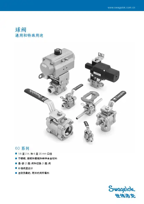
Valbart 球阀样本
- 格式:pdf
- 大小:5.20 MB
- 文档页数:36
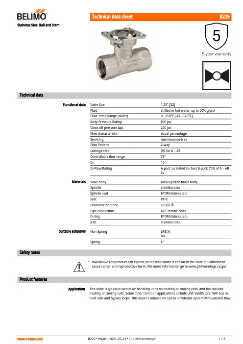
B229•ApplicationStainless Steel Ball and StemTechnical dataFunctional dataValve Size 1.25" [32]Fluidchilled or hot water, up to 60% glycol Fluid Temp Range (water)0...250°F [-18...120°C]Body Pressure Rating 600 psi Close-off pressure ∆ps 200 psiFlow characteristic equal percentage Servicing maintenance-free Flow Pattern 2-way Leakage rate0% for A – AB Controllable flow range 75°Cv10Cv Flow RatingA-port: as stated in chart B-port: 70% of A – AB CvMaterialsValve body Nickel-plated brass body Spindle stainless steel Spindle seal EPDM (lubricated)SeatPTFE Characterizing disc TEFZEL®Pipe connection NPT female ends O-ring EPDM (lubricated)Ballstainless steel Suitable actuators Non-Spring LRB(X)NR SpringLFSafety notesWARNING: This product can expose you to lead which is known to the State of California to cause cancer and reproductive harm. For more information go to Product featuresThis valve is typically used in air handling units on heating or cooling coils, and fan coil unit heating or cooling coils. Some other common applications include Unit Ventilators, VAV box re-heat coils and bypass loops. This valve is suitable for use in a hydronic system with variable flow.B229 Flow/Mounting detailsTwo-way valves should be installed with thedisc upstream.DimensionsDimensional drawingsLRB, LRXType DN Weight [kg][kg]B229320.60A B C D E F H1H29.4" [239] 3.7" [95]7.2" [184] 6.3" [161] 1.3" [33] 1.3" [33] 1.2" [30]0.6" [15]LFA B C D E F8.3" [211] 3.7" [95] 6.6" [167] 5.6" [142] 1.8" [46] 1.8" [46]ARB N4, ARX N4, NRB N4, NRX N4A B C D E F11.4" [289] 3.7" [95]7.8" [199]7.1" [181] 3.1" [80] 3.1" [80]LRB24-SR-T Modulating, Non-Spring Return, 24 V, for DC2...10 V or 4...20 mATechnical dataElectrical data Nominal voltage AC/DC 24 VNominal voltage frequency50/60 HzPower consumption in operation 1.5 WPower consumption in rest position0.2 WPower consumption for wire sizing 3 VATransformer sizing 3 VA (class 2 power source)Electrical Connection Screw terminal (for 26 to 14 GA wire)Overload Protection electronic thoughout 0...90° rotationFunctional data Operating range Y 2...10 VOperating range Y note 4...20 mA w/ ZG-R01 (500 Ω, 1/4 W resistor)Input Impedance100 kΩ for 2...10 V (0.1 mA), 500 Ω for 4...20 mAPosition feedback U 2...10 VPosition feedback U note Max. 0.5 mADirection of motion motor selectable with switch 0/1Manual override external push buttonAngle of rotation90°Angle of rotation note adjustable with mechanical stopRunning Time (Motor)default 90 s, variableNoise level, motor35 dB(A)Position indication Mechanically, pluggableSafety data Degree of protection IEC/EN IP54Degree of protection NEMA/UL NEMA 2Enclosure UL Enclosure Type 2Agency Listing cULus acc. to UL60730-1A/-2-14, CAN/CSAE60730-1:02, CE acc. to 2014/30/EUListed to UL 2043 - suitable for use in airplenums per Section 300.22(C) of the NEC andSection 602 of the IMCQuality Standard ISO 9001Ambient temperature-22...122°F [-30...50°C]Storage temperature-40...176°F [-40...80°C]Ambient humidity Max. 95% RH, non-condensingServicing maintenance-freeWeight Weight 1.1 lb [0.50 kg]LRB24-SR-TServicingAccessoriesElectrical accessoriesDescriptionType Battery backup system, for non-spring return models NSV24 US Battery, 12 V, 1.2 Ah (two required)NSV-BAT Auxiliary switch 1 x SPDT add-on S1A Auxiliary switch 2 x SPDT add-onS2AFeedback potentiometer 140 Ω add-on, grey P140A GR Feedback potentiometer 1 kΩ add-on, grey P1000A GR Feedback potentiometer 10 kΩ add-on, grey P10000A GR Feedback potentiometer 2.8 kΩ add-on, grey P2800A GR Feedback potentiometer 500 Ω add-on, grey P500A GR Feedback potentiometer 5 kΩ add-on, greyP5000A GRElectrical installationINSTALLATION NOTESProvide overload protection and disconnect as required.Actuators may be connected in parallel. Power consumption and input impedance must beobserved.Actuators may also be powered by DC 24 V.Only connect common to negative (-) leg of control circuits.A 500 Ω resistor (ZG-R01) converts the 4...20 mA control signal to 2...10 V.Actuators are provided with a numbered screw terminal strip instead of a cable.Meets cULus requirements without the need of an electrical ground connection.Warning! Live electrical components!During installation, testing, servicing and troubleshooting of this product, it may be necessary to work with live electrical components. Have a qualified licensed electrician or other individual who has been properly trained in handling live electrical components perform these tasks. Failure to follow all electrical safety precautions when exposed to live electrical components could result in death or serious injury.Wiring diagrams2...10 V / 4...20 mA ControlInstallation notesDimensions。
目录:球阀(二通阀,PN16) (2)VBA216 系列二通冷/热水调节球阀(DN20—DN80) (2)非弹簧复位型风门驱动器 (4)非弹簧复位型风门驱动器(5/10NM) (4)非弹簧复位型风门驱动器(20NM) (6)球阀(二通阀,PN16)VBA216 系列二通冷/热水调节球阀(DN20—DN80)应用•VBA216系列二通调节球阀广泛应用于,可用于冷冻水,热水,50%乙二醇溶液的HVAC 应用,它用于连续调节控制。
技术规格特点➢BSPP内螺纹连接;➢黄铜材质;➢低泄漏率(≤0.01% of Kvs)➢弹簧支撑的阀座可以最大限度的延长使用寿命➢V型固定半球,出口端敞开式设计,提供优秀的自清洁功能➢等百分比流通特性,精准定位,保证温度控制➢可实现执行器与球阀的轻松连接,提供手动操作功能➢可调流量比300:1➢转动角度90°(可调)材质及连接方式➢阀体:黄铜➢阀座:加强型PTFE(聚四氟乙烯)➢球体:不锈钢➢阀杆:不锈钢介质压力及温度范围:➢额定压力:PN16➢介质温度:水,-5~120℃选型说明订货型号口径Cv Kvs 关断力推荐驱动器扭力推荐驱动器型号VBA216-020P DN20 7.4 6.3 800KPa 5N·m CN7505A2001 VBA216-025P DN25 11.7 10 800KPa5N·m CN7505A2001 VBA216-032P DN32 18.7 16 800KPa5N·m CN7505A2001 VBA216-040P DN40 30.4 26 800KPa10N·m CN7510A2001 VBA216-050P DN50 46.8 41 800KPa10N·m CN7510A2001 VBA216-065P DN65 59.7 51 800KPa20N·m CN7220A2007 VBA216-080P DN80 94.8 81 800KPa20N·m CN7220A2007注意事项➢可安装在水平或者垂直管道上➢在安装驱动器之前先用扳手往返旋动阀杆数次➢注意水流方向非弹簧复位型风门驱动器非弹簧复位型风门驱动器(5/10NM )应用CN 系列风门执行器适用于电动风门控制,并可作为球阀的执行器,广泛应用于HVAC 领域。
美国博雷球阀选型样本
博雷球阀是一种广泛应用于工业系统中的关阀装置,它采用球体作为
阀体,通过旋转球体来控制介质的通断。
美国是球阀的主要制造和使用国
家之一,拥有丰富的博雷球阀选型样本。
下面将介绍一些具有代表性的美
国博雷球阀选型样本,并对其特点进行分析。
1.城市排污系统用球阀
这种球阀主要用于城市排污系统中的液体控制,包括污水、废水、雨
水等。
它采用全通径设计,具有流体阻力小的优点,能够保证系统中的液
体流动顺畅。
阀体和阀座采用碳钢材料制造,具有较高的强度和耐腐蚀性。
2.原油输送用球阀
这种球阀主要用于原油输送系统中,能够承受高温和高压的工况条件。
阀体和阀座采用不锈钢材料制造,具有良好的耐腐蚀性和耐磨损性。
球体
采用油封设计,能够有效防止介质泄漏,保证输送过程的安全性。
3.化工装置用球阀
这种球阀主要用于化工装置中的介质控制,包括酸碱溶液、腐蚀液体等。
阀体和阀座采用聚四氟乙烯材料制造,具有良好的耐腐蚀性和耐磨损性。
球体采用全包覆设计,能够有效防止介质泄漏,保证化工装置的安全
运行。
4.压缩空气系统用球阀
这种球阀主要用于压缩空气系统中的介质控制,包括空气、气体等。
阀体和阀座采用铝合金材料制造,具有轻便和耐腐蚀性。
球体采用多层密
封结构,能够有效防止介质泄漏,保证压缩空气系统的正常运行。
总的来说,美国博雷球阀选型样本种类繁多,面向不同的工业应用场景。
选型时需要综合考虑介质特性、工况条件、阀体材料、密封结构等因素,以确保球阀的使用效果和安全可靠性。
代号连接方式 内螺纹 外螺纹 法兰 承插焊 对焊 对夹 卡箍卡套NWFH SH BCKT6.连接型式代号注:密封副中两密封面材料不同时,用低硬度材料代号代号铬及铬锰系合金钢硬质合金 铜合金 渗氮钢蒙乃尔合金锡基轴承(巴氏)合金聚四氟乙烯密封面或衬里材料H Y T D M B F橡胶尼龙塑料衬胶衬铅衬搪瓷衬聚全氟乙丙烯衬聚三氟乙烯X N J Q C F46 F3代号密封面或衬里材料8. 密封副材料代号1.01.62.54.06.410.016.032.0101625406410016032015030040060080090015002500A1A3A4A6A8A9A15A251020456511014018010K 20K 45K 65K 110K 140K 180K15030040060080090015002500150Lb 300Lb 400Lb 600Lb 800Lb 900Lb 1500Lb 2500Lb16254064100162540641001625406410016025040016254064100160250400国家标准 美国标准 日本标准 英国标准 法国标准 德国标准MPa 代号 CLASS 代号 K 代号 CLASS 代号 Bar 代号 Bar 代号9.压力等级代号例如:国标阀门 - DN100; 美标阀门 4”;缩径阀门 DN100×80(公称×缩径);4” ×3”。
(公称×缩径)11.口径:为阀门的公称通径5.角行程气动执行机构代号气动方式代号双作用6H单作用(带复位弹簧)6T两段开两段关6P一段开两段关6V双作用6单作用(带复位弹簧)6K 带手轮传动装置6※W气开 气关6B注:执行机构按用户要求配置手动装置时,在后面加“W”代号结构形式1245768930PY形L形 T形三通式直通式浮动球四通式直通式三通式固定球摆动球直通直通(偏心)T L 半球(V型)7.结构形式代号轨道式M Co C 3C 4Z KQHTi代号C(PN16以上省略)I C 6C 9V P P 8P 1P 3R R 8R 1R 3代号碳钢ZG1Cr5Mo、C5WC6WC9铬钼钒钢铬镍钛钢超低碳铬镍钛钢铬镍钼钛钢超低碳铬镍钼钛钢钛钢蒙耐尔合金LCB LC3LC4灰铸铁可锻铸铁球墨铸铁Cr13系不锈钢铬钼钢低温钢主体材料主体材料10.阀门主体材料代号25、WCB、WCC ZG12Cr1MoV ZG15Cr2Mo1V ZG1G18Ni9Ti CF8、304ZG0G18Ni9TiCF3、304L ZG1G18Ni12Mo2TiCF8M 、316ZG0G18Ni12Mo2FiCF3M 、316LTi HT KTQT Cr13 0506球阀阀门型号及图号的编制方法球阀阀门型号及图号的编制方法1-阀体2-螺柱7-阀杆8-键13-螺钉14-O型圈18-O型圈19-阀座24-阀盖25-下轴对于用户有防火要求的球阀,均设有防火结构。
作为流程控制管线的承压设备之一,阀门阀体铸件的质量对于阀门寿命及人员和环境安全是最重要的,特别是在高温高压工况领域。
因此,顾客在考核与批准阀门制造商作为合格供应商之前,会预先对其阀门铸件进行审核认证。
供应范围和能力:等1:单座调节阀2:气动三偏心蝶阀3:夹套调节阀4:套筒调节阀5:电动三片式固定球阀6:高压调节阀组7:耐冲刷角型调节阀8:偏心旋转调节阀9:超低温调节阀10:V型调节球阀高温波纹管调节阀项目名称:尼龙66切片连续聚合项目介质名称:导热油工况参数:操作温度:320°C阀门类型:高温波纹管密封单座调节阀工况特点:介质温度高、渗透性强高温高压大口径调节阀项目名称:热电厂蒸汽减温站介质名称:蒸汽工况参数:介质温度430°C 阀前压力3.53MPa 阀后压力0.9MPa 阀门规格:10" Class 600, 16" Class 300工况特点:高温、高压、流速高、噪音大安全切断阀项目名称:输气管道工程站场系统阀门规格:口径6"、8"、10",压力等级Class 600工况参数:阀前压力:4-5.7MPa 关闭压差:5.7MPa 阀门要求:泄漏等级:V 级 故障位置:FC (紧急关闭)工况特点:采用现场管道介质(天然气)作为驱动源夹套调节阀项目名称:高含硫气田天然气处理厂工程装置名称:硫磺装车装置介质名称:液硫 工况参数:压力0.25MPa 温度125~135°C 工况特点:介质粘度高、易结晶超低温阀门项目名称:江苏LNG 接收站阀门用途:LNG 流量调节介质名称:LNG 液化天然气工况参数:温度-160°C ,阀前压力2~3MPa 工况特点:超低温超高压差调节阀项目名称:泥浆泵、压裂泵性能测试试验台阀门用途:用于泥浆泵及压裂泵试验设备加载系统介质名称:常温水工况参数:阀前105MPa 阀后 ≤1MPa 工况特点:超高压差、超宽流量调节范围口 径压力等级主体材料阀盖型式密封面形式流量特性可调范围工作温度操作方式设计标准阀门结构泄漏等级标准型、延长型、加长型、低温型FF、RF、RTJ、LF、BW等等百分比、直线、快开50:1-196°C~538°C气动、电动IEC60534直通球形阀体,单座柱塞型阀内件结构FCI 70-2 IV、V、VI级(软密封)3/4"~12"ANSI Class150~2500碳钢、不锈钢、合金钢、双相钢等内件材质结构长度不锈钢、合金钢、双相钢等ISA S75.03 (ANSI Class 150~600)ISA S75.16 (ANSI Class 900~2500)详细技术规格,请详见纽威调节阀选型样本应用领域:石油、化工、冶金、造船、电力、建材、液化天然气工业、轻工业等行业适用于泄漏要求较严,介质压差不大的场合CSS系列单座调节阀选配驱动装置:气动执行机构:PDL及PCL系列等电动执行机构:AUMA、ROTORK等应用领域:石油、化工、冶金、造船、电力、建材、液化天然气工业、轻工业等行业适用于介质压差较大的场合CSC系列套筒调节阀选配驱动装置:气动执行机构:PDL及PCL系列等电动执行机构:AUMA、ROTORK等直行程系列产品范围口 径压力等级主体材料阀盖型式密封面形式流量特性可调范围工作温度操作方式设计标准阀门结构泄漏等级标准型、延长型、加长型、低温型FF、RF、RTJ、LF、BW等等百分比、直线、快开50:1-196℃~538℃气动、电动IEC60534直通球形阀体,压力平衡型内件结构FCI 70-2 IV、V、VI级(软密封)1-1/2"~20"ANSI Class150~2500碳钢、不锈钢、合金钢、双相钢等内件材质结构长度ISA S75.03 (ANSI Class 150~600)ISA S75.16 (ANSI Class 900~2500)详细技术规格,请详见纽威调节阀选型样本不锈钢、合金钢、双相钢等产品范围CTD(M)系列分(合)流三通调节阀选配驱动装置:应用领域:造纸、化工、石油、化纤、电力、冶金制药、环保等工业领域适用于对盐酸、硫酸、氢氟酸、硝酸、王水等各种强酸,强碱和强氧化剂介质的调节控制气动执行机构:PDL 及PCL 系列等电动执行机构:AUMA 、ROTORK 等选配驱动装置:应用领域:石油、化工、冶金、造船、电力、建材、液化天然气工业、轻工业等行业适用于介质分流或合流的场合气动执行机构:PDL 及PCL 系列等电动执行机构:AUMA 、ROTORK 等产品范围口 径压力等级 3/4"~8"ANSI Class150主体材料WCB 衬F46或PFA详细技术规格,请详见纽威调节阀选型样本IEC60534产品范围阀盖型式密封面形式流量特性可调范围工作温度操作方式标准型、延长型、加长型、低温型FF 、RF 、RTJ 、LF 、BW 等直线50:1-196°C~538°C 气动、电动口 径压力等级主体材料1"~12"ANSI Class150~600碳钢、不锈钢、合金钢、双相钢等内件材质结构长度ISA S75.03 (ANSI Class 150~600)详细技术规格,请详见纽威调节阀选型样本设计标准阀门结构泄漏等级不锈钢、合金钢、双相钢等IEC60534三通球形阀体,柱塞型阀内件结构FCI 70-2 IV 、V 、VI 级(软密封)CFS 系列衬塑调节阀选配驱动装置:应用领域:石油、化工、冶金、航天、航空、船舶、核动力、军工等领域适用于对介质有严格密封要求的场合气动执行机构:PDL 及PCL 系列等电动执行机构:AUMA 、ROTORK 等应用领域:石油、化工、冶金、航天、航空、船舶、核动力、军工等领域适用于对介质有严格密封要求的场合CBC 系列波纹管密封套筒调节阀选配驱动装置:气动执行机构:PDL 及PCL 系列等电动执行机构:AUMA 、ROTORK 等产品范围口 径压力等级主体材料3/4"~8"ANSI Class150~1500碳钢、不锈钢、合金钢、双相钢等阀盖型式密封面形式流量特性可调范围工作温度操作方式标准型、延长型、加长型、低温型FF 、RF 、RTJ 、LF 、BW 等等百分比、直线、快开50:1-196°C~538°C 气动、电动波纹管材质304,316,316Ti,INCONEL 等。

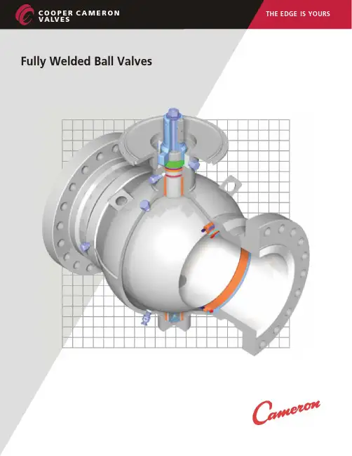
C O O P E R C A M E R O N V A LV ES1FULLY WELDED BALL VALVESFULLY WELDED BALL VALVES Features and Benefits2, 3, 4 & 5In-line Sphere Launcher 6Accessories7HOW TO ORDER Standards, Specifications and Materials 8 & 9DIMENSION TABLES ASME/ANSI Class 150 through 2500 (PN 20 through PN 420)Full and Reduced Port Valves 10 through 22API PRESSURE CLASS 2000, 3000 & 5000 psiFull and Reduced Port Valves23, 24 & 25DIMENSION TABLES Actuator Mounting Information26, 27 & 28PIPING INFORMATION TABLE29TERMS AND CONDITIONS30 & 31TRADEMARK INFORMATION32TABLE OF CONTENTSTC145512/04 NP-5MP卡 麦 隆 全 焊 接 球 阀目 录全焊接球阀特点和优点管线清管球发送器附件如何购买卡麦隆球阀标准、规范和材料尺寸表全通径和缩径球阀全通径和缩径球阀尺寸表执行机构安装信息管子尺寸表商务条款和条件商标信息CO O P E R C A M E R O N V A LV E S2Engineered for heavy duty, maintenance free performance, the Cameron Fully Welded Ball Valve is commonly selected for a number of applications, including:One of the most trusted valves in the petroleum industry, itcombines the strength of forged components with a lightweight and compact spherical design.Cameron Fully Welded Ball Valves satisfy ASME/ANSI 150 through 2500 (PN 20 through PN 420) and API 2000 through10,000 standards. Made of forged steel to assure uniform fine grain structure and toughness, they may be specified in sizes from 2 in. to 56 in. (50 mm to 1400 mm).FEATURES AND BENEFITS•Gas transmission •NGL plants •Products pipeline •NGL pipeline •Measurements skids •Compressor stations •Dehydration systems •CO services 2•Gas separation systems •Offshore •Natural gas storage •Subsea•Dryer serviceTC145512/04 NP-5MFULLY WELDED BALL VALVES卡 麦 隆 全 焊 接 球 阀特 点 和 优 点石油工业中最值得信赖的阀门, 综合了轻型锻件的强度和紧凑式球形设计。
上装式球阀选型样本Product catalog of top entry ballvalvesCoosai温州科赛阀门有限公司Wenzhou coosaivalveco.,ltd企业简介科赛阀门有限公司坐落在中国泵阀之乡——温州瓯北,厂区紧临104国道,东临温州机场,南临温州火车站,交通便利。
科赛阀门有限公司是一家专业生产阀门、阀门驱动装置、过滤器、及隔膜泵等产品的生产企业。
阀门设计和制造标准有API6D ,API609、GB/T4213。
阀门产品等级class150~class2500,公称通径1/2"~48",工作温度-29℃~425℃,阀体材料主要为ASTM A216-WCB 。
可以根据客户要求冶炼和制造。
电动执行机构有PSL、PSQ 和HQ 三大类,控制模式有4~20mA 标准信号和现场总线。
隔膜泵分气动隔膜泵和电动隔膜泵两大类。
公司拥有数控车床、数控铣床等加工设备70多台套以及各种测量器具,并辅以CAD 计算机辅助设计,保证了公司产品的设计检测和制造能力。
公司贯彻执行ISO9001:2000质量体系,严格按照产品标准设计检测和制造(CE API),遵守相关的法律和法规,确保产品安全可靠,满足客户的要求。
欢迎光临科赛公司指导!Brief introductionWenzhou Kesai Valve Co.,Ltd is located in “china pump &valve town”——Oubei ,which is along side the national highwayG104,and is not far from wenzhou airport and train station.Itenjoys a very convenient transportation.We Coosai (brand name of Wenzhou Kesai Valve Co.,Ltd),mainly manufactures various kinds of valves,valve actuators,strainers and diaphragm pumps and so on according to API6D,API609GB/T4213and also our own company’s manufacturing standard,.with pressure ranges from class 150~class 2500,size 1/2"~48",and temperature -29℃~425℃.Also,we can produce invarious kinds of materials according to customers’requirements.Our electric actuators covers PSL,PSQ,HQ series,which can be controlled by 4~20mA analog signals as well as field bus.Besides,we produce pumps like air operated diaphragm pumps and electric operated diaphragm pumps and so on.We Coosai possesses 70sets of advanced digital lathes,digital milling machines,testing equipments etc.,further more,Coosai is assisted with CAD design system,all these guarantees our designing,manufacturing and testing capability.As an ISO9001:2000(CE,API)granted company we design and manufacture strictly according to international standards,to make sure we produce the reliable products for you.Welcome to Coosai.CONTENTS产品目录上装式球阀型号编制方法Establishment method of Top entry ball valve model (3)SQ347对焊上装式球阀SQ347Top entry ball valv(Butt-welding) (4)SQ347法兰上装式铸钢球阀SQ347Top entry ball valve(flange) (7)质量服务承诺Commitment on quality service (9)附录防火防静电设计Appendix(About the structure and work principle) (10)上装式球阀型号说明Establishment method of top entry ball valve model1类型代号Code of type 上装式球阀Top entry ball valveSQ2传动形式代号Code of driving type 蜗轮Worm gear 3气动Pneumatic 6电动Electric93连接形式代号Code of connection type 螺纹Threaded1法兰Flange4浮动球直通Full bore floating ball固定球直通Full bore trunnion mountedball4结构形式代号Code of structural form 17氟塑料Fluorine plastic硬质合金Hard alloy石墨Graphite橡胶Rubber合金钢Alloy steel5密封面材料代号Code of materials for valve seat F YSXH 6公称压力Code of nominal pressure GB162025405064CLASS150300灰铸铁Gray iron球墨铸铁Ductile iron碳钢Carbon steel 不锈钢Stainless steel7阀体材料代号Code of materials for valve bodyZ Q C P说明Note:1、型号编制Model explanation如一阀体材料为WCB ,公称压力为150LB,密封面材料为四氟,结构为浮动球直通式,法兰连接的上装式球阀,其型号编制为:SQ41F150C 。
阀门产品样本罗浮阀门集团有限公司目录1、A21型PN16~40外螺纹连接弹簧封闭微启式安全阀 (1)2、A21型PN64~100外螺纹连接弹簧封闭微启式安全阀 (2)3、A21型PN160~320外螺纹连接弹簧封闭微启式安全阀 (3)4、A27H-10、A27H-16型外螺纹连接弹簧带扳手微启式安全阀 (4)5、A28H型PN16外螺纹连接弹簧带扳手全启式安全阀 (5)6、A37H、A43H型PN16~40双联弹簧带扳手微启式安全阀 (6)7、A38Y型PN16~40双联弹簧带扳手全启式安全阀 (8)8、A40Y型PN16~64带散热片弹簧封闭全启式安全阀 (10)9、A41H、A41Y型PN16~100弹簧封闭微启式安全阀 (12)10、A41Y型PN160~320弹簧封闭微启式安全阀 (15)11、A42F 、A42Y、KA42Y(抗硫)型PN16~100弹簧封闭全启式安全阀 (17)12、42Y型PN160~320弹簧封闭全启式安全阀 (21)13、WA42Y型PN16~40波纹管弹簧全启式安全阀 (22)14、A44Y型PN16~100弹簧封闭带扳手全启式安全阀 (22)15、A44Y型PN160~320弹簧封闭带扳手全启式安全阀 (26)16、A47H型PN16~40弹簧带扳手微启式安全阀 (27)17、A48Y型PN16~100弹簧带扳手全启式安全阀 (29)18、A48SH型PN16~40弹簧带扳手全启式安全阀 (32)19、A48SH型PN64~160高温高压弹簧带扳手全启式安全阀 (34)20、A42Y-P5545V、A62Y-P55 140V型气控碟形弹簧安全阀 (36)21、A68Y型对焊连接弹簧全启式安全阀 (37)22、A49H-40型主安全阀及配套GA49H-40型冲量安全阀 (38)23、A49Y-100、A49Y-100V型主安全阀及其配套冲量安全阀 (40)24、A69Y-P54140V型DN100主安全阀及其配套冲量安全阀 (42)25、A69Y-100、A69Y-100V型DN150主安全阀及其配套冲量安全阀 (43)26、GA41H型PN16~40杠杆式安全阀 (44)27、GA42H型PN16~100单杠杆式安全阀 (45)28、GA44H型PN16~64双杠杆式安全阀 (47)29、A411F-25、A412F-25、NA42F-25型内装式安全阀 (48)30、JA22H-2.5、JA22W-2.5P型外螺纹连接静重式安全阀 (50)31、FA72W型PN10真空负压安全阀 (51)32、AH42F型平衡式安全回流阀 (52)33、A61型弹簧微启式安全阀 (53)34、AY42H PN400型、LA802Y-600型安全溢流阀 (55)35、石化专用安全阀 (57)36、AQ-20型空压机安全阀 (58)37、LFA46F型先导式安全阀系列 (59)封1、A21型PN16~40外螺纹连接弹簧封闭微启式安全阀使用范围:本产品可用于石油、化工行业。
Series WE07 2-Piece Flanged Stainless Steel V-Ball ValveSpecifications - Installation and Operating InstructionsBulletin V-WE07The Series WE07 2-Piece Flanged Stainless Steel V-Ball Valve incorporates a V-port ball valve for impressive flow rates with minimal pressure drop. Quarter turn control ball valves are compact, lighter weight and much less expensive than comparable sized globe valves and segmented control valves. They also offer bubble tight shut off with zero leakage and can withstand high pressure drops. The 60° and 90° balls offer an equal percentage flow characteristic. W. E. Anderson’s V-port ball valves have been designed to offer maximum flow characteristics that are substantially higher than comparably sized globe valves. The natural flow pattern of ball valves increases flow rates and in many applications valves smaller than pipeline size can be used. Actuators are direct mounted creating a compact assembly for tight spaces. Limit switches can be mounted directly to the valves allowing for remote position indication. The Series WE07 can be configured with an electric or pneumatic actuator. Electric actuators are available in weatherproof or explosion-proof, a variety of supply voltages and two-position modulating control.Two-position actuators use the supply voltage to drive the valve open or close, while the modulating actuator accepts a 4-20 mA input for valve positioning. Actuators feature thermal overload protection and a permanently lubricated gear train.The pneumatic double acting actuator uses an air supply to drive the valve open and closed. The actuator has two supply ports with one driving the valve open and the other driving the valve closed. Spring return pneumatic actuators use the air supply to open the valve and internally loaded springs return the valve to the closed position. Also available is the SV3 solenoid valve to electrically switch the air supply pressure between the air supply ports for opening and closing the valve. Actuators are constructed of anodized and epoxy coated aluminum for years of corrosion freeservice.WE07-DHD00-TWE07-DDA01-T-AA03WE07-DTD01-T-AWE07-DDA01-T-NN09WE07-CTI01-T-AVALVE BILL OF MATERIALSVALVE DIMENSIONAL DRAWINGCv Valve Charts90° V-PORT – Cv60° V-PORT – Cv Pressure/Temperature Rating ChartAUTOMATED VALVE DRAWINGSWITH PNEUMATIC ACTUATORWITH ELECTRIC ACTUATORWITH EXPLOSION-PROOF ELECTRIC ACTUATORPNEUMATIC ACTUATORNote: For optimal operation, pneumatic actuators should be run with a supply of clean, lubricated air.Spring Return Actuator OperationAir to PORT 2 (the left hand port) causes the actuator to turn counterclockwise (CCW). Loss of air to PORT 2 causes air to exhaust and the actuator turns clockwise (CW). This is the FAIL CLOSE operation.Double Acting Actuators OperationAir to PORT 2 (the left hand port) causes the actuator to turn counterclockwise (CCW). Air to PORT 1 (the right hand port) causes the actuator to turn clockwise (CW).Pneumatic Actuator MaintenanceRoutine maintenance of pneumatic actuator:• Keep the air supply dry and clean• Keep the actuator surface clean and free from dust• Periodic checks should be done to make sure all fittings are tight • P neumatic actuators are supplied with lubrication to last the entire life span ofthe actuator under normal operating conditions. The outer surface of the pneumatic actuator should be clean to avoid friction or corrosion. All fittings and connections should be tight to prevent leaks during operation. Check the bolts mounting the valve to the actuator to make sure they have not come loose during shipping or installation. Make sure the valve and actuator are not rubbing or jamming against other components during operation. The actuator should be inspected annually to make sure all fittings and bolts are tight and nothing has come loose during operation.Disassembling Pneumatic ActuatorsBefore beginning disassembly, ensure that the air supply to the actuator has been disconnected, all accessories have beenremoved, and that the actuator has been disassembled from the valve.1. L oosen the end cap fasteners (23) with a wrench (size varies depending onactuator model). On the spring return actuator, alternate 3 to 5 turns on each fastener until the springs are completely decompressed. Use caution when removing the cap since the springs are under load until the fasteners are fully extended.2. R emove the pinion snap ring (13) with a lock ring tool. The indicator (12) maynow be removed.3. T urn the pinion shaft (2) counter clockwise until the pistons are at the full end oftravel. Disengage the pistons (15) from the pinion. (Note: Low pressure air--3 to 5 psi MAXIMUM--might be required to force the pistons completely from the body.) Note the position of the pistons before removing them from the actuator body. 4. R emove the pinion through the bottom of the actuator. The actuator is nowcompletely disassembled.Be sure the actuator surfaces are free of debris and scratches before reassembling.1. Apply a light film of grease to all O-rings and the pinion before replacing.2. P ut the pinion (2) back through the actuator with the flats of the pinion shaftrunning parallel with the body.3. W hen reassembling the actuator, make sure that the piston racks are square tothe actuator body and returned to their original orientation. (Note: The normal operation of all spring return pneumatic actuators is FAIL CLOSED. To change the orientation to FAIL OPEN, rotate the racks 180º to create a reverse operation.4. W hen replacing springs in a spring return actuator, ensure that the springs arereplaced in their identical position in the end cap from which they were removed. (Note: In some circumstances, you might want to change the standard 80 pound spring set to fit your application and available air pressure.5. S eal the end caps with a petroleum lubricant and bolt to actuator body.6. C heck the seal of the actuator by covering seal areas (pinion, end caps) withsoapy water and using low pressure air to the actuator to ensure that no bubbles are produced.Reassembling Pneumatic ActuatorsWhen working on the Actuator/Valve assembly, disconnect the air or power supply to the actuator. Spring return actuators/valves may change position if power fails or is removed. Never insert any object or body part into the valve body. Severe injury may occur.Pneumatic Actuators Bill of MaterialsELECTRIC ACTUATORSElectric Installation1. Operate valve manually and place in the open position.2. R emove any mechanical stops the valve might have. (DO NOT REMOVE ANYPARTS NECESSARY FOR THE PROPER OPERATION OF THE VALVE, SUCH AS THE PACKING GLAND, PACKING NUT, ETC.)3. E nsure that the actuator output shaft and valve stem are aligned properly. If theyare not, operate the valve manually until they are correct.4. Remove actuator cover.5. B ring power to the actuator. CAUTION: Make sure power is OFF at the mainbox.6. W ire the actuator per the diagram attached to the inside of the cover. Specialactuators (those with positioner boards, etc.) will have diagrams enclosed inside the cover.7. S ecurely tighten bolts used to mount the actuator to a mounting bracket ordirectly to the valve mounting pad if it is ISO5211 compliant.8. C ycle the unit several times and check the open and closed positions of thevalve. Cams are pre-adjusted at the factory; due to the variety of valve designs and types however, slight adjustments might be required.9. Replace cover and tighten screws.To Set The Open Position1. C ycle the valve to the open position by applying power to terminals. The top camand switch control this position. In the open position, the set screw in the top cam will be accessible.2. If the valve is not open completely:A. Slightly loosen the set screw on the top cam.B. R otate the cam clockwise (CW) by hand until the switch makes contact.Contact is made when a slight click can be heard. By making incremental CW movements of the top cam, the valve can be positioned precisely in the desired position.C. When the top cam is set, tighten the set screw securely.3. If the valve opens too far:A. A pply power to terminals. This will begin to rotate valve CW. When valve isfully open and in the exact position desired, remove power from actuator.B. Loosen the set screw in the top cam.C. R otate the top cam counterclockwise (CCW) until the switch arm drops offthe round portion of the cam onto the flat section. A slight click can be heard as the switch changes state.D. Continue applying power to terminals until valve is in the desired position.To Set The Closed Position1. A pply power to terminals to move the valve toward the closed position. Thebottom cam and switch control the closed position. In the closed position, the set screw in the bottom cam will be accessible.2. If the valve is not closed completely:A. Slightly loosen the set screw on the bottom cam.B. R otate the cam counterclockwise (CCW) by hand until the switch makescontact. Contact is made when a slight click can be heard. By making incremental CCW movements of the bottom cam, the valve can be positioned precisely in the desired position.C. When the top cam is set, tighten the set screw securely.3. If the valve closes too far:A. A pply power to terminals. This will begin to rotate valve CCW. When valve isfully closed and in the exact position desired, remove power from actuator.B. Loosen the set screw in the top cam.C. R otate the top cam clockwise (CW) until the switch arm drops off the roundportion of the cam onto the flat section. A slight click can be heard as the switch is no longer making contact with the round part of the cam.D. Continue applying power to terminals until valve is in the desired position.Electric Actuators Wiring Diagram: ACT-TI & ACT-MIWiring Diagrams forTI01-A to TI05-A: 110 VAC, TI01-B to TI05-B: 220 VAC, TI01-C to TI05-C: 24 VACHOTALVE ALVEWiring Diagrams for TI01-D to TI05-D: 24 VDCOPERATION:POWER TO 1 & 2 FOR CCW ROTATION POWER TO 3 & 4 FOR CW ROTATION TERMINALS 5 & 6 FOR FIELD LIGHT INDICATION CONNECTIONSW.#1 SW.#2SWITCH #1 OPEN SWITCH SWITCH #2 CLOSE SWITCHWiring Diagrams forMI01-A to MI05-A: 110 VAC, MI01-B to MI05-B: 220 VAC, MI01-C to MI05-C: 24 VACSW. 1, CLOSESW. 2, OPEN .SW. 3, CLOSE SW. 4, OPEN Wiring Diagrams forMI01-D to MI05-D: 24 VDCSW. 1, CLOSESW. 2, OPEN .SW. 3, CLOSE SW. 4, OPENElectric Actuators Wiring Diagram: ACT-TD & ACT-MDWiring Diagrams forTD01-A to TD03-A: 110 VAC, TD01-B to TD03-B: 220 VAC,TD01-C to TD03-C: 24 VACWiring Diagrams forTD01-D to TD03-D: 24 VDCWiring Diagrams forMD01-A to MD03-A: 110 VAC, MD01-B to MD03-B: 220 VAC,MD01-C to MD03-C: 24 VACNote: To speed up installation of the control wires to the ACT-MDXX modulating actuator, it is recommended to remove the control module from the actuator. The control module can be removed by removing the two mounting screws on the left and right of the control module. Install the control wires to the correct terminal points and then reinstall the control module.Electric Actuator MaintenanceOnce the actuator has been properly installed, it requires no maintenance. The gear train has been lubricated and in most cases will never be opened. Duty Cycle Definition“Duty Cycle” means the starting frequency.Formula: Running Time ÷ (Running Time + Rest Time) x 100% = duty cycle –> Rest Time = Running Time x (1 - duty cycle) ÷ duty cycleFor example: The running time is 15 seconds30% duty cycle 15 x [(1 - 30%) / 30%] = 35 –> The rest time will be 35 seconds 75% duty cycle 15 x [(1 - 75%) / 75%] = 5 –> The rest time will be 5 seconds If the duty cycle is higher, the rest time will be shortened, which means the starting frequency will be higher.Thermal OverloadAll actuators are equipped with thermal overload protection to guard the motor against damage due to overheating.Mechanical OverloadAll actuators are designed to withstand stall conditions. It is not recommended to subject the unit to repeated stall conditions.Explosion-Proof Electric Actuators1. DO NOT under any circumstances remove the cover of the actuator while in a hazardous location. Removal of the coverwhile in a hazardous location could cause ignition of hazardous atmospheres.2. D O NOT under any circumstances use an explosion-proof electric actuator in ahazardous location that does not meet the specifications for which the actuator was designed.3. A lways verify that all electrical circuits are de-energized before opening theactuator.4. A lways mount and cycle test the actuator on the valve in a non-hazardouslocation.5. W hen removing the cover, care must be taken not to scratch, scar of deform theflame path of the cover and base of the actuator, since this will negate the NEMA rating of the enclosure.6. W hen replacing the cover, take care that the gasket is in place to assure properclearance after the cover is secured. 7. A ll electrical connections must be in accordance with the specifications for whichthe unit is being used.8. S hould the unit ever require maintenance, remove from the hazardous locationbefore attempting to work on the unit. If the actuator is in a critical application, it is advisable to have a standby unit in stock.11Electric Actuators Performance Rating MAINTENANCE/REPAIRUpon final installation of the Series WE, only routine maintenance is required. The Series WE is not field serviceable and should be returned if repair is needed. Field repair should not be attempted and may void warranty.WARRANTY/RETURNRefer to “Terms and Conditions of Sale” in our catalog and on our website. Contact customer service to receive a Return Goods Authorization number before shipping the product back for repair. Be sure to include a brief description of the problem plus any additional application notes©Copyright 2022 Dwyer Instruments, Inc.Printed in U.S.A. 7/22FR# 444259-00 Rev. 512NOTES____________________________________________________________________________________________________________________________________________________________________________________________________________________________________________________________________________________________________________________________________________________________________________________________________________________________________________________________________________________________________________________________________________________________________________________________________________________________________________________________________________________________________________________________________________________________________________________________________________________________________________________________________________________________________________________________________________________________________________________________________________________________________________________________________________________________________________________________________________________________________________________________________________________________________________________________________________________________________________________________________________________________________________________________________________________________________________________________________________________________________________________________________________________________________________________________________________________________________________________________________________________________________________________________________________________________________________________________________________________________________________________________________________________________________________________________________________________________________________________________________________________________________________________________________________________________________________________________________________________________________________________________________________________________________________________________________________________________________________________________________________________________________________________________________________________________________________________________________________________________________________________________________________________________________________________________________________________________________________________________________________________________________________________________________________________________________________________________________________________________________________________________________________________________________________________________________________________________________________________________________________________________________________________________________________________________________________________________________________________________________________________________________________________________________________________________________________________________________________________________________________________________________________________________________________________________________________________________________________________________________________________________________________________________________________________________________________________________________________________________________________________________________________________________________。
Medium Pressureto 22,500 psi (1,550 bar)High Pressureto 65,000 psi (4,500 bar)Ultra High Pressureto 152,000 psi (10,500 bar)Valve ActuatorsCustomized SolutionsBall Valvesto 21,000 psi (1,500 bar)Adapters and CouplingsAccessoriesToolsTechnicalInformation Ball Valve Index Page:2-Way Ball Valves 2 – 3 3-Way Ball Valves4 – 5Pneumatic and Electric Actuators6 – 10Ball Valves feature:• One-piece, trunnion mounted style stem design eliminates shear failure found in two-piece stem designs.• Choice of 3/16”, 1/4”, 3/8” and 1/2” ball orifices provides minimalpressure drops.• Re-torqueable seat glands for longer seat life and dependability.• Torlon Ball Seat material offers excellent sealing capabilities.• 316 cold worked stainless steel body, and 17-4 PH stem offersexcellent corrosion resistance.• Ball valves are available in 90˚ and 180˚ open to close with apositive stop.• Available with Pneumatic or Electric actuators.• Available in medium, high, BSP and NPT pressure connections.• Full materials traceability.• Safety weep holes for all pressure connections and packing area.MAXIMATOR ball valves provide superior quality and performance with a variety of valve styles and process connections. All medium and high pressure connections are supplied with glands and collars.MAXIMATOR offers a complete line of high pressure components to compliment the 2-way and 3-way Ball Valve line.Note: When selecting multiple items, the pressure rating would be that of the lowest rated component.Medium Pressure to 22,500 psi (1,550 bar)High Pressureto 65,000 psi (4,500 bar)Ultra High Pressure to 152,000 psi (10,500 bar)Valve ActuatorsCustomized SolutionsBall Valvesto 21,000 psi (1,500 bar)Adapters and Couplings AccessoriesTools TechnicalInformation2-Way Ball Valves2-Way Ball Valves are available with 1/4”, 3/8“ or 1/2“ orifices and are capable of safe handling of liquids and gases up to 21,000 psi (1,500 bar) pressure. Their 90° handle rotation allows for full flow capabilities with minimal pressure drop. Robust one-piece trunnion style stem design eliminates shear failure that is found in a two-piece stem design.Ball seats are made of Torlon material providing excellent sealing capabilities with low handle operating torque. Re-torqueable seat glands provide longer valve life and dependability. Standard valves are supplied with FKM O-Rings rated to 300°F (150°C).Ordering Information Typical catalog number: 21B244MManually Operated 2-Way Ball Valve Pressure Temperature Ratings21B244MOptionsPressure ( x 1000 psi ) Valve Series Orifice Diameter Connection Type 10 = 10,000 psi (690 bar) B2 = Ball Valve 2-way 4 = 1/4” See chart See Ball Valve Actuators 15 = 15,200 psi (1,050 bar) 6 = 3/8” (page 3)(page 4 & 5)21 = 21,000 psi (1,500 bar)8 = 1/2”Valve Orifice Dimensions in. (mm) Valve Block Models Size Panel Thick- in. (mm) A B C D E F H I J K hole ness 15B24 1/4 21B24 (6.4)15B26 3/821B26 (9.5)10B28 1/2(12.7)4.41 1.95 0.80 0.28 0.47 1.52 4.02 3.33 2.01 4.21 1.03 1.02 (112) (49.5) (20.3) (7) (12) (38.5) (102) (84.5) (51) (107) 26.2) (26) 4.96 2.5 1.09 0.28 0.39 25.87 5.08 2.99 5.55 1.42 1.38 (126) (63.5) (27.8) (7) (10) (50.8) (149) (129) (76) (141) (36) (35)5.9 3.07 1.31 0.28 0.49 3 10.35 4.16 7.761.54 1.772 (149.8) (78) (33.4) (7) (12.5) (76.2) (263)(105) (197.2)(39)(45)ValveBlockPanelThick-K holeMedium Pressureto 22,500 psi (1,550 bar)High Pressure to 65,000 psi (4,500 bar)Ultra High Pressureto 152,000 psi (10,500 bar)Valve ActuatorsCustomized SolutionsBall Valvesto 21,000 psi (1,500 bar)Adapters andCouplingsAccessoriesToolsTechnicalInformation All dimensions are for reference only and subject to change.21B244M 21,000 (1,500) 1/4 4MF 0.106 (2.7) 0.25 21B246M 21,000 (1,500) 3/8 6MF 0.203 (5.1) 0.91 21B249M 21,000 (1,500) 9/16 9MF 0.250 (6.4) 1.51 21B244H 21,000 (1,500) 1/4 4HF 0.094 (2.4) 0.20 21B246H 21,000 (1,500) 3/8 6HF 0.125 (3.2) 0.30 21B249H 21,000 (1,500) 9/16 9HF 0.188 (4.8) 0.681/4“ 15B242P 15,200 (1,050) 1/8 FNPT 0.250 (6.4) 1.51 15B244P 15,200 (1,050) 1/4 FNPT 0.250 (6.4) 1.51 15B246P 15,200 (1,050) 3/8 FNPT 0.250 (6.4) 1.51 15B248P 15,200 (1,050) 1/2 FNPT 0.250 (6.4) 1.51 15B242B 15,200 (1,050) 1/8 FBSP 0.250 (6.4) 1.5115B244B 15,200 (1,050) 1/4 FBSP 0.250 (6.4) 1.51 15B246B 15,200 (1,050) 3/8 FBSP 0.250 (6.4) 1.51 15B248B 15,200 (1,050) 1/2 FBSP 0.250 (6.4) 1.51 21B266M 21,000 (1,500) 3/8 6MF 0.203 (5.1) 0.91 21B269M 21,000 (1,500) 9/16 9MF 0.307 (7.8) 1.91 21B2612M 21,000 (1,500) 3/4 12MF 0.374 (9.5) 3.51 15B266P 15,200 (1,050) 3/8 FNPT 0.374 (9.5) 3.51 3/8“15B268P15,200 (1,050)1/2FNPT0.374 (9.5)3.5115B2612P 15,200 (1,050) 3/4 FNPT 0.374 (9.5) 3.51 15B266B 15,200 (1,050) 3/8 FBSP 0.374 (9.5) 3.51 15B268B 15,200 (1,050) 1/2 FBSP 0.374 (9.5) 3.51 15B2612B 15,200 (1,050) 3/4 FBSP 0.374 (9.5) 3.51 10B2812M 10,000 (690) 3/4 12MF 0.437 (11.1) 4.40 10B2816M 10,000 (690) 1 16MF 0.500 (12.7) 7.60 1/2“10B2812P 10,000 (690) 3/4 FNPT0.500 (12.7)7.6010B2816P 10,000 (690) 1 FNPT 0.500 (12.7) 7.60 10B2812B 10,000 (690) 3/4 FBSP 0.500 (12.7) 7.6010B2816B 10,000 (690) 1 FBSP 0.500 (12.7) 7.60Orifice Catalog Pressure Rating OD Tubing Connection Orifice Size Cv Series Number @ RT psi. (bar) Size in. Type in. (mm)Medium Pressureto 22,500 psi (1,550 bar)High Pressureto 65,000 psi (4,500 bar)Ultra High Pressureto 152,000 psi (10,500 bar)Valve ActuatorsCustomized SolutionsBall Valvesto 21,000 psi (1,500 bar)Adapters and CouplingsAccessoriesToolsTechnicalInformation3-Way Ball ValvesManual 3-Way Ball Valve 3-Way, 180° Switching StyleOpen Closed OpenOpen Open3-Way, 90° Diverting Style21B3S34MOptionsPressure ( x 1000 psi ) Valve Series Orifice Diameter Connection Type 10 = 10,000 psi (690 bar) B3S = 180° Switching 3 = 3/16” See chart See Ball Valve Actuators 15 = 15,200 psi (1,050 bar) B3D = 90° Diverting 6 = 3/8” page 5(page 4 & 5)21 = 21,000 psi (1,500 bar)8 = 1/2”3-Way Ball Valves have 3/16”, 3/8“ or 1/2“ orifices and are capable of safe handling of liquids and gases up to 21,000 psi (1,500 bar) pres-sure. Robust one-piece trunnion style stem design eliminates shear failure that is found in a two-piece stem design. There are two styles in the 3-way design:The 180˚ rotating Switching Ball Valve is designed to have fluid enter in through the bottom connection and can be switched to either side connection. Also, the valve can be closed in the center “Off” position.The 90˚ rotating Diverting Ball Valve is designed to have fluid enter in through the bottom connection and can be diverted to either side connection. There is no center off position in the diverting design.Ordering Information Typical catalog number: 21B3S34MValve Orifice Dimensions in. (mm) Valve Block Models Size Panel Thick- in. (mm) A B C D E F H I J K L hole ness5.71 2.26 1.11 0.28 0.47 1.52 4.02 3.33 2.5 4.65 0.98 1.03 1.02(145) (57.5) (28.3) (7) (12) (38.5) (102) (84.5) (63.5) (118) (25) (26.2) (26)6.55 2.89 1.50 0.28 0.39 2 5.87 5.08 2.99 5.76 1.19 1.42 1.38(166.4) (73.3) (38) (7) (10) (50.8) (149) (129) (76) (146.2) (30.2) (36) (35) 7.83 3.35 1.69 0.28 0.49 3 10.2 4.13 7.78 1.7 1.81 1.77 (199) (85.1) (42.9) (7)(12.5) (76.2) (259) (105) (191.5) (43.2) (43.2)(45)15B3D315B3S3 3/1621B3D3 (4.8)21B3S315B3D6 3/8 15B3S6 (9.5)10B3D8 1/210B3S8 (12.7)G - Panel mounting screw thread size 10-24 UNC (screw included). All dimensions are for reference only and are subject to change.Medium Pressureto 22,500 psi (1,550 bar)High Pressure to 65,000 psi (4,500 bar)Ultra High Pressure to 152,000 psi (10,500 bar)Valve Actuators Customized SolutionsBall Valvesto 21,000 psi (1,500 bar)Adapters andCouplingsAccessories Tools Technical Information * Maximum side connection inlet pressure is 15,000 psig.All dimensions are for reference only and subject to change. See page 2 for pressure/temperature rating chart.21B3S34M 21B3D34M 21,000 (1,500) 1/4 4MF0.106 (2.7)0.20 21B3S36M 21B3D36M 21,000 (1,500) 3/8 6MF 0.188 (4.8) 0.50 21B3S39M 21B3D39M 21,000 (1,500) 9/16 9MF 0.188 (4.8) 0.50 21B3S34H 21B3D34H 21,000 (1,500) 1/4 4HF 0.091 (2.3) 0.15 21B3S36H 21B3D36H 21,000 (1,500) 3/8 6HF 0.125 (3.2) 0.30 21B3S39H 21B3D39H 21,000 (1,500) 9/16 9HF 0.188 (4.8) 0.50 3/16“15B3S32P 15B3D32P 15,200 (1,050) 1/8 FNPT 0.188 (4.8) 0.50 15B3S34P 15B3D34P 15,200 (1,050) 1/4 FNPT 0.188 (4.8) 0.50 15B3S36P 15B3D36P 15,200 (1,050) 3/8 FNPT 0.188 (4.8) 0.50 15B3S38P 15B3D38P 15,200 (1,050) 1/2 FNPT 0.188 (4.8) 0.50 15B3S32B 15B3D32B 15,200 (1,050) 1/8 FBSP 0.188 (4.8) 0.50 15B3S34B 15B3D34B 15,200 (1,050) 1/4 FBSP 0.188 (4.8) 0.50 15B3S36B 15B3D36B 15,200 (1,050) 3/8 FBSP 0.188 (4.8) 0.50 15B3S38B 15B3D38B 15,200 (1,050) 1/2 FBSP 0.188 (4.8) 0.5015B3S69M 15B3D69M 15,200 (1,050) 9/169MF0.307 (7.8)1.65 15B3S612M 15B3D612M 15,200 (1,050) 3/4 12MF 0.322 (8.2)2.10 15B3S64P 15B3D64P 15,200 (1,050) 3/8 FNPT 0.250 (6.4) 2.10 3/8“15B3S66P15B3D66P15,200 (1,050)1/2FNPT0.250 (6.4)2.10 15B3S68P 15B3D68P 15,200 (1,050) 3/4 FNPT 0.322 (8.2) 2.10 15B3S64B 15B3D64B 15,200 (1,050) 3/8 FBSP 0.250 (6.4) 2.10 15B3S66B 15B3D66B 15,200 (1,050) 1/2 FBSP 0.250 (6.4) 2.10 15B3S68B 15B3D68B 15,200 (1,050) 3/4 FBSP 0.322 (8.2) 2.1010B3S812M 10B3D812M 10,000 (690) 3/412MF0.437 (11.1)3.90 10B3S816M 10B3D816M 10,000 (690) 1 16MF 0.494 (12.5)4.40 1/2“10B3S812P 10B3D812P 10,000 (690) 3/4 FNPT 0.494 (12.5) 4.40 10B3S816P 10B3D816P 10,000 (690) 1 FNPT 0.494 (12.5) 4.40 10B3S812B 10B3D812B 10,000 (690) 3/4 FBSP 0.494 (12.5) 4.40 10B3S816B 10B3D816B 10,000 (690) 1 FBSP 0.494 (12.5) 4.40Orifice Catalog NumberPressure RatingOD Tubing Connection Orifice Size CvSeries3-Way 180° 3-Way 90° @ RT psi. (bar)*Size in.Type in. (mm)Switching DivertingMedium Pressureto 22,500 psi (1,550 bar)High Pressureto 65,000 psi (4,500 bar)Ultra High Pressureto 152,000 psi (10,500 bar)Valve ActuatorsCustomized SolutionsBall Valvesto 21,000 psi (1,500 bar)Adapters and CouplingsAccessoriesToolsTechnical Information • Pneumatic actuators are designed to be used with2-way & 3-way style ball valves for remote operation.• Two styles available:Double acting: (air to open / air to close) Single acting: (air to open / spring to close)• Optional limit switches with visual indication available.• Actuators are anodized aluminum, which provides goodcorrosion resistance. Stainless steel material is available upon request.• Maximum operating air pressure is 145 psi (10 bar).• I nlet air supply connection is 1/8” FNPT • Actuator operating temperature:-4˚F to 203˚F (-20°C to 95°C).• Minimal required air pressure is 80 psi (5.5 bar).• Opening & closing time is less than one second.Pneumatic Actuator FeaturesOrdering InformationSimply add suffiix to the manual ball valve catalog number:DA = Double Acting Air Actuators SA = Single Acting Air ActuatorsAir Operated 3-Way Ball Valve, 90° Diverter Style Air Operated 3-Way Ball Valve,180° Switching StyleAir Operated 2-Way Ball ValveMedium Pressureto 22,500 psi (1,550 bar)High Pressureto 65,000 psi (4,500 bar)Ultra High Pressureto 152,000 psi (10,500 bar)Valve ActuatorsCustomized SolutionsBall Valvesto 21,000 psi (1,500 bar)Adapters and CouplingsAccessoriesToolsTechnical Information • Electric actuators are designed to be used with2-way & 3-way style ball valves for remote operation.• Actuators will accept a wide range of single phaseinput voltages from 12 to 240 volts DC or AC current.• Optional limit switches with visual indication available.• Manual override option is standard.• Actuators are made with polyamide material,which provides good corrosion resistance.• Actuator operating temperature:-0˚F to 160˚F (-18°C to 70°C).• Opening & closing time is less than ten secondswith 90° actuators.Electric Actuator FeaturesOrdering InformationSimply add suffiix to the manual ball valve catalog number:EA = Electric Actuator, 12 - 240 Volts AC or DCElectrically Operated 2-Way Ball Valve Electrically Operated 3-Way Ball ValveMedium Pressureto 22,500 psi (1,550 bar)High Pressureto 65,000 psi (4,500 bar)Ultra High Pressureto 152,000 psi (10,500 bar)Valve ActuatorsCustomized SolutionsBall Valvesto 21,000 psi (1,500 bar)Adapters and CouplingsAccessoriesToolsTechnical Information • Pneumatic actuators are designed to be used with2-way & 3-way style ball valves for remote operation.• Two styles available:Double acting: (air to open / air to close) Single acting: (air to open / spring to close)• Optional limit switches with visual indication available.• Actuators are anodized aluminum, which provides goodcorrosion resistance. Stainless steel material is available upon request.• Maximum operating air pressure is 145 psi (10 bar).• I nlet air supply connection is 1/8” FNPT • Actuator operating temperature:-4˚F to 203˚F (-20°C to 95°C).• Minimal required air pressure is 80 psi (5.5 bar).• Opening & closing time is less than one second.Pneumatic Actuator FeaturesOrdering InformationSimply add suffiix to the manual ball valve catalog number:DA = Double Acting Air Actuators SA = Single Acting Air ActuatorsAir Operated 3-Way Ball Valve, 90° Diverter Style Air Operated 3-Way Ball Valve,180° Switching StyleAir Operated 2-Way Ball ValveMedium Pressureto 22,500 psi (1,550 bar)High Pressureto 65,000 psi (4,500 bar)Ultra High Pressureto 152,000 psi (10,500 bar)Valve ActuatorsCustomized SolutionsBall Valvesto 21,000 psi (1,500 bar)Adapters and CouplingsAccessoriesToolsTechnical Information • Electric actuators are designed to be used with2-way & 3-way style ball valves for remote operation.• Actuators will accept a wide range of single phaseinput voltages from 12 to 240 volts DC or AC current.• Optional limit switches with visual indication available.• Manual override option is standard.• Actuators are made with polyamide material,which provides good corrosion resistance.• Actuator operating temperature:-0˚F to 160˚F (-18°C to 70°C).• Opening & closing time is less than ten secondswith 90° actuators.Electric Actuator FeaturesElectrically Operated 2-Way Ball Valve Electrically Operated 3-Way Ball ValveOrdering InformationSimply add suffiix to the manual ball valve catalog number:EA = Electric Actuator, 12 - 240 Volts AC or DCMedium Pressureto 22,500 psi (1,550 bar)High Pressureto 65,000 psi (4,500 bar)Ultra High Pressureto 152,000 psi (10,500 bar)Valve ActuatorsCustomized SolutionsBall Valvesto 21,000 psi (1,500 bar)Adapters and CouplingsAccessoriesToolsTechnical Information • Pneumatic actuators are designed to be used with2-way & 3-way style ball valves for remote operation.• Two styles available:Double acting: (air to open / air to close) Single acting: (air to open / spring to close)• Optional limit switches with visual indication available.• Actuators are anodized aluminum, which provides goodcorrosion resistance. Stainless steel material is available upon request.• Maximum operating air pressure is 145 psi (10 bar).• I nlet air supply connection is 1/8” FNPT • Actuator operating temperature:-4˚F to 203˚F (-20°C to 95°C).• Minimal required air pressure is 80 psi (5.5 bar).• Opening & closing time is less than one second.Pneumatic Actuator FeaturesOrdering InformationSimply add suffiix to the manual ball valve catalog number:DA = Double Acting Air Actuators SA = Single Acting Air ActuatorsAir Operated 3-Way Ball Valve, 90° Diverter Style Air Operated 3-Way Ball Valve,180° Switching StyleAir Operated 2-Way Ball ValvePipe Valves & Fittings to 15,200 psi (1,050 bar)Medium Pressure to 22,500 psi (1,550 bar)High Pressure to 65,000 psi (4,500 bar)Ultra High Pressure to 152,000 psi (10,500 bar)Valve ActuatorsCustomized Solutions Ball Valves to 21,000 psi (1,500 bar)Products for Sour Gas Applications Adapters and Couplings Accessories ToolsTechnical Information 10 | 11Ball Valve Actuators» Electric Actuators • Electric actuators are designed to be used with 2-way & 3-way style ball valves for remote operation.• Actuators will accept a wide range of single phase input voltages from 12 to 240 volts DC or AC current.• Optional limit switches with visual indication available.• Manual override option is standard.• Actuators are made with polyamide material,which provides good corrosion resistance.• Actuator operating temperature:-0˚F to 160˚F (-18°C to 70°C).• Opening & closing time is less than ten seconds with 90° actuators.Electric Actuator FeaturesElectrically Operated 2-Way Ball Valve Electrically Operated 3-Way Ball Valve3999.1827 | 04/2017All technical and dimensional information subject to change. All general Terms and Conditions of sale, including limitations of our liability, apply to all products and services sold.All dimensions are for reference only and subject to change.Electric Actuators - 1/2“ Two Way, 1/2“ Three WayOrdering Information Simply add suffiix to the manual ball valve catalog number:EA = Electric Actuator, 12 - 240 Volts AC or DC。
1The TMCBV is manufactured in Milan, Italy as a joint venture between Flowserve and Valbart known as Flowserve/Valbart Flow Control Srl. The TMCBV merges the robust, proven Valbart trunnion-guided pipeline valve design with advanced Flowserve technologies for characterized control and noise attenuation. We designed the TMCBV to be a more compact, less expen-sive choice in services in which it had been previously necessary to use a larger, more expensive valve style.The TMCBV is designed to operate at high pressures while minimizing the torque needed to operate the valve. The seats are spring-preloaded and process energized for Class IV or Class V shutoff at any pressure. The TMCBV‘s capacity is greater than that of a comparable globe valve - allowing the customer to use a smaller TMCBV. The customer receives cascading savings from using a smaller, lighter valve. It requires a smaller, less expensive actuator and lighter, less expensive pipe supports. Delivery charges are reduced, and the smaller valve is easier to install in tight piping runs.Rotary seals, precision machining, and accurate trunnion guiding, all contribute to zero external leakage, ensuring that the TMCBV meets all environmental standards.IntroductionTo achieve a Cv of 9,000 in a Class 300 valve bodyProduct Range2Difference in cost and weightBody StylesS3N1N2The TMCBV system offers more trim choices than any other valve in the industry. Let us optimize your application with our technology.The Z1 and Z2 trims use angled plates to give a pro-gressive, continuous characteristic while forcing the flow through multiple self-cleaning stages. Z-trims serve for cavitation control prevention and for noise attenuation up to 20dB.Noise-control trims are based on Valtek’s Megastream technology.The N1 trim controls velocity as it stages the pressure drop across flat plates in the bore of the ball, progressively decreasing the resistance as the flow encounters fewer plates as the valve is opened. 10-20 dB attenu-ation can be expected. The N2 trim is more advanced and uses multiple baffles to absorb pressure drops in steps and to acoustically prevent noi-se by wave-front cancellation as well as tuned resonance in high, less-audible frequencies. Attenuation of up to 30dB may be realized.Flowserve Corporation has established industry leadership in the design and manufacture of its products. When properly selected, this Flowserve product is designed to perform its intended function safely during its useful life. However, the purchaser or user of Flowserve products should be aware that Flowserve products might be used in numerous applications under a wide variety of industrial service conditions. Although Flowserve can (and often does) provide general guidelines, it cannot provide specific data and warnings for all possible applications. The purchaser/user must therefore assume the ultimate responsibility for the proper sizing and selection, installation, operation, and maintenance of Flowserve products. The purchaser/user should read and understand the Installation Operation Maintenance (IOM) instructions included with the product, and train its employees and contractors in the safe use of Flowserve products in connection with the specific application.While the information and specifications contained in this literature are believed to be accurate, they are supplied for informative purposes only and should not be considered certified or as a guarantee of satisfactory results by reliance thereon. Nothing contained herein is to be construed as a warranty or guarantee, express or implied, regarding any matter with respect to this product. Because Flowserve is continually improving and upgrading its product design, the specifications, dimensions and information contained herein are subject to change without notice. Should any question arise concerning these provisions, the purchaser/user should contact Flowserve Corporation at any one of its worldwide operations or offices.© 2010 Flowserve Corporation, Irving, Texas, USA. Flowserve is a registered trademark of Flowserve Corporation.RGLimitorqueFlowserve Valbart Flow Control Srl 20050 Mezzago (Milan) Italy Phone: +39.039.624111Fax: +Flowserve Houston Business Development 5909 West Loop South, Suite 200Bellaire, TX 77401 Phone: 713 218 4200 Fax: 713 218 4247。
福斯公司福斯Valbart固定式控制球阀
佚名
【期刊名称】《流程工业》
【年(卷),期】2012(000)016
【摘要】福斯推出的福斯Valbart固定式控制球阀(TMCBV).可降低噪声、控制气蚀并为用户提供更佳的可靠性。
【总页数】1页(P61-61)
【正文语种】中文
【中图分类】TB114.3
【相关文献】
1.福斯加适达(CASSIDA)让设备的运行获得更多帮助——访福斯润滑油(中国)有限公司特种油销售总监周立康 [J], 申海鹏
2.福斯润滑油:用尖端润滑科技护航中国制造业--访福斯润滑油(中国)有限公司工业润滑油销售副总裁安德·巴斯蒂安(Dr. Andreas Bastian)博士 [J], 樊有海
3.驾驭美国"福斯"跑车驰骋全球——访"马可·波罗奖"得主、美国福斯公司总裁兼首席执行官陆克林 [J], 龙微微
4.福斯达之路──福斯达纸业(烟台)有限公司采访记 [J], 周政;
5.福斯公司福斯Valbart固定式控制球阀 [J],
因版权原因,仅展示原文概要,查看原文内容请购买。