德力西DZ 标准断路器选型手册
- 格式:pdf
- 大小:2.67 MB
- 文档页数:6
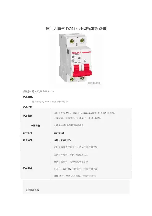
德力西电气DZ47s 小型标准断路器
关键字:德力西,断路器,DZ47s
产品简介:
德力西电气 DZ47s 小型标准断路器
产品介绍
产品描述
适用于交流50Hz,额定电压230V/400V的低压终端配电系统;
主要功能:短路保护、过载保护、控制、隔离。
产品功能过载保护\短路保护\隔离功能。
符合证书CCC\CB\CE
符合标准\IEC /EN60898-1
产品特点采用全球领先产品平台,产品性能更加稳定全新附件附件,保护功能更加全面
全新外观设计,传承经典红色手柄
全系列一致的6kA分断能力,性能更加优越增加1P+N,3P+N两种级数,规格更加全面
主要性能参数。
外形及安装尺寸
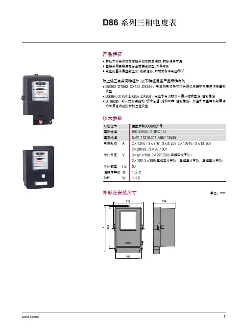
产品特征
转动元件采用双宝石轴承和双转盘结构,转动稳定可靠 基架采用高强度铝合金锭铸造成型,
不易变形 电压线圈采用塑封工艺,
密封性好,可耐受脉冲电压6KV
除上述三点共同特征外,以下特征是各产品所特有的
DS862、DT862、DX862、DX865:电压和电流铁芯均采用优质硅钢片高速冲床叠铆
成型
DS864、DT864、DX863、DX864:电压和电流铁芯采用分磁板固定,
性能稳定 DT862K :嵌入式安装结构,
设计合理,结构可靠,性能稳定;底座和表盖等外部零件均采用阻燃ABS 材料注塑成型
技术参数
单位:mm
接线图
三相三线有功电度表经电压
电流互感器接入式
三相三线有功电度表经电流 互感器接入式
三相三线有功电度表直接接入式
三相三线无功电度表经电压、 电流互感器接入式 三相三线无功电度表经电流 互感器接入式
三相四线无功电度表经电压、 电流互感器接入式 三相四线无功电度表经电流 互感器接入式
三相四线有功电度表经电压、 电流互感器接入式 三相四线有功电度表经电流 互感器接入式
三相四线无功电度表直接接入式
选型指南
订货示例:
如客户需要三相四线有功电度表,电压为220/380V ,
准确等级为2,电流为1.5(6)A,功能为互感式,则相对应的订货编码为:DT862MQ26M4H
注:1. 1)规格代码中的“M ”
表示电流倍数 2. 2)
互感式功能的仅供1.5(6)A 和3(6)A 规格3. DT862中参比电压57.7/100V 、DS862中参比电压100V 、DX862中参比电压100V ,
以上三种 情况下基本电流为1.5(6)A 、3(6)A。

A 一级配电A1 框架断路器01-5051-5556-6768-71A2 高压隔离开关A3高压熔断器A4三相干式变压器快速选型CDW6 框架断路器CDW1 框架断路器DW15 框架断路器DW17 框架断路器DW16 框架断路器3-78-2223-3637-4142-4748-5053-5354-5455-5558-5960-6061-6263-6465-6667-6770-7071-71快速选型GW9-12 单极隔离开关GN19-10 高压隔离开关快速选型XRNP1 高压限流熔断器RN 高压限流熔断器XRNT1 高压限流熔断器XRNM1 高压限流熔断器RW 高压跌落式熔断器快速选型SBK 三相干式变压器A1 框架断路器A 一级配电产品描述主要适用于配电网络中,用来分配电能,以及保护线路和设备免受过载、短路、接地等故障的危害,可避免不必要的停电,提高供电系统的可靠性、连续性和安全性符合标准国际标准 IEC 60947-1、IEC 60947-2、IEC 60947-4国家标准 GB/T 14048.1、GB 14048.2、GB 14048.4CDW6CDW1DW15DW17DW162A 1 框架断路器CDW6 框架断路器CDW6单选附件指南如果您需要更多扩展功能,可单独选购附件 (请参看附件编码订货)附件编码用于附加远程操作功能的附件CDW6DCP 直流电源模块 输入DC220/110V 输出DC28V 2000-6300AF CDW6R继电器模块 AC250V/DC38V 2000-6300AF该产品技术参数详见此样本第8-22页3A 1 框架断路器缆绳联锁CDW6FL2固定式缆绳联锁 (二台)CDW6FL3固定式缆绳联锁 (三台)CDW6DL2抽屉式缆绳联锁 (二台)CDW6DL3抽屉式缆绳联锁 (三台)杠杆联锁CDW6DG2杠杆联锁 (二台)CDW6DG3杠杆联锁 (三台)CDW1 框架断路器本体部分默认标准配置附件: 分励,欠压,合闸,电操,4开4闭辅助触头,门框(2500A 以上规格),相间隔板,辅助接线端子47回路,M 型脱扣器该产品技术参数详见此样本第23-36页4A 1 框架断路器CDW1附件配置附件名称表DW15 框架断路器本体部分默认标准配置附件: 线圈(分励、欠压、合闸),控制箱(630A ),电操,通用继电器(1600A 以上),一组3开3闭辅助触点,2500和5000壳架默认为6开6闭该产品技术参数详见此样本第37-41页5A 1 框架断路器附件配置附件配置6A 1 框架断路器DW16 框架断路器本体部分默认标准配置附件: 分励,欠压,电操,一组3开3闭辅助触点,杠杆操作手柄(630-2000A)该产品技术参数详见此样本第48-50页7A 1 框架断路器框架断路器CDW6壳架等级2000A 、3200A 、6300A 额定电流 In (A)630~6300额定电压 Ue (V)400极数 3极,4极安装方式固定式,抽屉式智能控制器L 型基本功能:保护功能 (L, S, I & G)M 型基本保护功能, 基本测量功能, 辅助功能H 型基本与高级保护功能, 多种测量功能, 辅助功能 &通讯功能远程操作分励脱扣器, 欠压脱扣器, 合闸电磁铁, 电动机操作机构 &辅助触头外接互感器N 相外接互感器, 接地互感器, 漏电互感器锁分闸锁, 门联锁连接绳索联锁, 杠杆联锁, 相间隔板控制单元附件交流电源模块, 直流电源模块, 继电器模块操作门框 , 透明防护罩附件技术参数8A 1 框架断路器额定运行短路分断能力Ics 5080100额定短时耐受电流Icw(1s)506585使用寿命机械寿命 有维护1000080005000机械寿命无维护250025002500电气寿命 有维护10001000800电气寿命 无维护500500500L型智能控制器A 1 框架断路器自诊断功能故障历史记录测试功能A 1 框架断路器动作电流Isd 0.4~15In+OFF 整定步长10kA 以下:≤2A, 10kA 以上≤10A 2Ig 0.2 1.0In+OFF动作时间tG0.1s, 0.2s, 0.3s, 0.4s, OFFH型智能控制器A 1 框架断路器动作电流I R OFF+0.4 1.0In 保护曲线SI: 标准反时限类型选择VI: 快速反时限EI(G): 特快反时限(配电)EI(M): 特快反时限(电动机)动作电流Ig OFF+0,2~1.0xIn 反时限剪切系数Cr 1.5~6, +OFF 延时时间tg0.1~1s分励线圈远程操作功能介绍在断路器储能后,能够在规定的电源电压下,通过远程遥控操作,使断路器断开A 1 框架断路器欠压线圈及欠压延时线圈合闸线圈电动机操作机构功能介绍在断路器储能并通电后,当断路器电压下降到70%-35%的额定电压时,能够动作,使断路器断开。
德力西断路器使用说明(原创版)目录1.德力西断路器的选用和安装2.德力西断路器的质量和品牌保障3.德力西断路器的接线方法4.德力西断路器的型号和参数5.德力西断路器的使用注意事项正文德力西断路器是一种用于保护电路安全的设备,它可以在电路发生过载或短路时自动切断电源,防止电路过载和火灾事故的发生。
在选用和安装德力西断路器时,需要注意以下几点:首先,要根据电路的负载能力和使用环境来选择合适的断路器型号和规格。
一般来说,德力西断路器的选用要考虑到电路的额定电压、额定电流和断路能力等因素。
例如,对于电源电路,应选用机座 160A 断路器整定电流 80A 的型号,这样可以保证电路的安全运行。
其次,在安装德力西断路器时,要确保安装位置正确,并且接线牢固可靠。
一般来说,电源应接在断路器的电源侧(上端),负载应接在断路器的负载侧(下端)。
同时,在安装过程中,还需要检查断路器的外观和接线端子是否完好无损,以保证电路的安全运行。
德力西断路器的质量和品牌保障是消费者在选择产品时需要考虑的重要因素。
作为中国 500 强企业,德力西电气在产品质量和品牌形象方面都有着较高的保障。
德力西断路器采用优质的材料和先进的工艺制造,具有较高的可靠性和稳定性。
只要购买到正品,德力西断路器的质量是可以信赖的。
在接线德力西断路器时,需要按照接线图进行操作,确保接线正确无误。
一般来说,德力西断路器的接线比较简单,电源接在断路器的电源侧(上端),支路如果有断路器全部并联在总断路器的负载侧(下端)。
其支路断路器,分别接负载(用电器)。
德力西断路器的型号和参数是消费者在选择产品时需要关注的重要信息。
例如,德力西 dz47-63 小型断路器接线比较简单,适用于家用和工业用电。
而 CDM1 系列断路器则是一种高分断能力的断路器,适用于电源电路和工业用电路等。
在选择德力西断路器时,需要根据电路的实际情况和需要来选择合适的型号和参数。
在使用德力西断路器时,还需要注意以下几点:首先,要按照电路的实际情况和需要来选择合适的断路器型号和规格;其次,在安装和使用过程中,要确保接线牢固可靠,防止接线松动或短路;最后,要定期检查和维护断路器,确保其正常运行。

安装、使用产品前,请仔细阅读使用说明书并妥善保管、备用安全告知在安装、操作、运行、维护、检查之前,请务必认真阅读本说明书,并按照说明书上的内容准确安装、使用本产品。
危险:严禁湿手操作断路器; 使用中,严禁触摸导电部位;维护与保养时,必须确保产品不带电; 严禁用短路的办法来测试产品。
注意:安装、维护与保养时,应由具有专业资格的人员操作;产品的各项特性出厂时已整定,使用中不能自行拆装或随意调节; 使用前请确认产品工作电压、额定电流、频率及特性是否符合工作要求; 按照产品上的接线标识进行安装接线(负载端即出线端);导线伸入接线孔后拧紧接线螺钉,拧紧导线使导线不得松动、拔出,裸露铜线头不能露在接线端外; 本产品对同时接触被保护电路两线引起的触电危险不能进行保护;本产品防护等级IP20不具备防尘功能,当用于灰尘较多的场合时,请安装于密封较好的终端箱中;本产品不适用于电动机频繁启动、电热设备、电容柜、高感性、高容性负载和高温环境等特殊场合;如果产品在开箱时有破损或异常响声,应立即停止使用并联系供应商。
电源侧有电压时,合闸后产品中线路板处在工作状态,侧面有一定温度,属于正常现象;目录1主要用途及适用范围 ....................................................... 错误!未定义书签。
2产品型号及含义 . (1)2.1产品型号及含义 (1)2.2面板介绍 (2)3 正常工作条件和安装条件 (2)4技术特性 (3)4.1 分类 (3)4.2 主要技术参数 (3)4.3 主要技术性能 (4)5外形及安装尺寸 (4)6安装、使用和维护 (5)7故障分析 (6)8 开箱检查 (7)9公司承诺 (7)1主要用途及适用范围DZ47sLES系列剩余电流动作断路器(以下简称漏电断路器)具有漏电(触电)、过载、短路等保护功能,还可根据用户的需要增加过压,欠压保护功能。
DZ47sLES漏电断路器适用于交流50/60Hz,额定电压230V/400V,额定电流至63A及以下的线路中,用来对人的间接接触保护,以及对建筑物及类似用途的线路进行过电流保护。
DZ47sZ-63DC MOULDED CASE CIRCUITBREAKERNA VIGATORSeriesUser ManualPlease read the product instructions carefully before the installation and use of the product, and keep those instructions properly for reference later.DZ47sZ-63 DC MOULDED CASE CIRCUIT BREAKERUser ManualSafety NoticePlease carefully read this manual before the installation, operation, run, maintenance, and inspection of the product, and install and operate this product properly according to the product instructions.Danger:●It is prohibited to operate the circuit breaker with your wet hands;●t is prohibited to touch the conductive part during operation;●Make sure that the product is de-electrified during the maintenance and repair;●It is prohibited to use the short circuit method to test the product;Caution●The installation, maintenance, and repair shall be carried out by the qualified professionals;●When installation, connect the wires according to the wiring method shown in Fig. 5 and the “+” and “-” poles marked on the product properly to prevent reverse connection;●All characteristics of the product have been set in the factory, and the product cannot be disassembled without permission or adjusted at will during operation;●Confirm that the operating voltage, rated current and characteristics of the product meet the working requirements before use;●In order to prevent short circuit between the phases, the exposed wire or copper busbar at the terminal block shall be subject to the insulation treatment;●If found any damage or abnormal sound when unpacking, please stop the product and contact the supplier;●When scrapping the product, please dispose the industrial wastes properly. Thanks for your cooperation. About DZ47sZ-63 DC Moulded Case Circuit Breaker●About panelCheck the positive and negative poles,and connect the wires according to thewiring diagram!Fig. 1 Panel introductionLegends:1 Positive pole of circuit2 Terminal block3 Company logo4 Product model (DZ47sZ)5 Rated current (see Table 1)6 Setting current (see Table 1)7 Rated voltage and breaking capacity (see Table 1)8 Certification mark 9 Wiring indication 10 Terminal block 11 Positive pole of circuit breaker12 Reference standard 13 Use category 14 Rated impulse withstand voltageNormal Operation, Installation and Transportation Conditions●Normal operation and installation conditions(1)The upper limit of the ambient air temperature shall not exceed +60°C, the lower limit shall not exceed -20°C, and the mean temperature shall not exceed +35°C within 24 hours;(2)The altitude of the installation site does not exceed 2000m;(3)When the maximum temperature is +40°C, the relative humidity of the air does not exceed 50%; a higher relative humidity is allowed at lower temperatures; for example, the relative humidity does not exceed 90% at +20°C. Special protection measures should be taken for condensation occurred occasionally due to temperature changes;(4)The external magnetic field near the installation site of the circuit breaker should not exceed 5 times of the geomagnetic field in any direction;(5)Installed in a medium without explosion hazard, and there is gas and dust sufficient to cause metal corrosion and damage to the insulation;(6)Installed in places where there is no obvious impact and vibration and no rain and snow attacks;(7)Pollution degree: Level 2;(8)Installation category: Class II, Class III;(9)The product shall be installed in a power distribution tank, distribution cabinet or box;(10)When wiring, the power supply end must be connected to the positive pole of the circuit breaker, the load end must be connected to the negative pole of the circuit breaker, and reverse wiring connection is not allowed;●Normal storage and transportation conditions(1) The lower limit of temperature is not below -40°C, and the upper limit does not exceed +70°C;(2) Relative humidity (at 25°C) does not exceed 95%;(3) Please handle the product gently during transportation, do not upside it down, and prevent it from violent collision as much as possible.Main technical performance parameters●The main technical parameters of the circuit breaker are listed in Table 1.Table 1 Main technical parametersSetting current Rated current In A Numberof polesRated voltageUe VRated breakingcapacity Icn kA(B)Ii=5.5In 6, 8, 10, 13, 16, 20,25, 32, 40, 50, 631 250V62, 3 500V(C)Ii=8.5In 1, 2, 3, 4, 5, 6, 8, 10, 13,16, 20, 25, 32, 40, 50, 631 250V2, 3 500V● The overcurrent protection characteristics of the circuit breaker are listed in Table 2Table 2: Overcurrent protection characteristics of circuit breakers ReleasetypeRatedcurrent InATest current A Starting state Test time Expected results Remarks Referencetemp.(B) Ii=5.5In(C) Ii=8.5In≤631.05In Cold state t ≤1h No trip --+30+50o C(B) Ii=5.5In (C) Ii=8.5In 1.30In Followedby testt<1h TripThe current rises to the specified valuewithin 5s(B) Ii=5.5In 5.5Inx80% Cold statet ≤0.2s No tripTurn on theaux. switch, and connect thepower supply(C) Ii=8.5In 8.5Inx80%(B) Ii=5.5In 5.5Inx120% t<0.2s Trip(C) Ii=8.5In 8.5Inx120%● The protection characteristics curves of circuit breaker are illustrated in Fig. 2 and Fig. 3Fig. 2 B type thermal / electromagnetic tripcharacteristics curve Fig. 3 C type thermal / electromagnetic tripcharacteristics curveOutline and Installation DimensionsThe circuit is rail-mounted, and its outline and installation dimensions are shown in Fig. 4.Unit: mmFig. 4 Outline and installation dimensionsInstallation, Operation and Maintenance●Before installing circuit breaker:(1)Check whether the technical parameters on the label meet the use requirements;(2)Before use, the user should use a 500V megohmmeter to check that the insulation resistance between the poles (except for single pole), the poles and the shells, the poles and the mounting rails, and the inlet and outlet terminals of the circuit breaker should not be less than 5MΩ. If the insulation resistance is less than 5MΩ, stop the product and contact the supplier for replacement in time;(3)Close and open the circuit breaker several times and check whether the circuit breaker operating mechanism is blocked and whether the mechanism works reliably;(4)The reference temperature of this series of circuit breakers is +30+50°C. If there are multiple circuit breakers in the sealed box, the temperature of the box will increase accordingly, and the working current is 0. 8In;(5)The cross-sectional area of the connecting conductor should be adapted to the rated current of the circuit breaker, see Table 3;Table 3: Rated current and cross-sectional area of connecting wiresRated current A 1, 2, 3,4, 5, 610, 13 16, 20 25 32 40, 50 63Sectional area of wire mm2 1 1.5 2.5 4 6 10 16 Min. length of connecting wirem1 1 1 1 1 1 2(6) This series of circuit breakers is of the rail-mounted type, suitable for TH35-7.5 steel mounting rails;(7) When the ambient temperature changes, the rated current value shall be corrected accordingly. Temperature correction coefficients are listed in Table 4.Table 4 Table of temperature coefficients for rated currentRated current Rated current correction value A●Install the circuit breaker according to the wiring method shown in Fig. 5;1P single pole 2P 2 poles 2P 2 poles 2P 2 polesUn (Rated voltage)Lower inlet Upper inlet Lower inlet Upper inlet Lower inlet Upper inlet Lower inlet ApplyLoad3P 3 poles Lower inlet Lower inlet Lower inlet Lower inlet Lower inlet Lower inletUn (Rated voltage)Notes: (1) L+ is the positive pole of power supply, L- is the negative pole of power supply(2) ○+is the positive pole of circuit breaker, and ○-is the negative pole of circuit breaker(3) In the DC power supply, the "L-" is usually earthed, and the neutral pole "M" in the positive and negative power supply system is earthed.Fig. 5 Wiring methodUnpacking InspectionAfter unpacking, the user must check whether the product is intact, whether the exposed metal is rusty, and whether the product is defects due to poor transportation or storage. If found the above phenomenon, please stop the product, and contact the supplier timely for solution.Company’ commitmentThe free repair or replacement will be provided by the company for damage or abnormal operation of the product produced by our company due to poor manufacturing quality within 36 months from the date of the production under the premise that the user conforms to the operation and storage conditions and that the product is well sealed.A paid repair is provided when the warranty period expires. However, the paid repair is provided for damage caused by one of the following situations even within the warranty period:(1)Improper operation, maintenance, or storage;(2)Modification without permission, or improper maintenance;(3)Damage caused by falling off after purchase or occurred during the installation process;(4)Irresistible nature disasters such as earthquakes, fires, lightning strikes, and abnormal voltages.If you have any questions, please contact the dealer or the company’s customer service department.Customer service hotline: 400-826-8008Ordering NoticePlease specify the following contents when ordering:a)Name, model and spec. of circuit breaker;b)Rated current and the number of poles of circuit breaker;c)Qty.For example, to order DZ47sZ-63 1-pole circuit, C type, rated current 20A, 1000 unit, please specify: DZ47sZ-63/1P, C20, 1000 units.Certificate DELIXI ELECTRIC LTD Name: DC Moulded Case Circuit Breaker Model: DZ47sZ-63The product passes the inspection, and is allowed to be shipped.Standard: GB/T 14048.2Inspector: Check 06Date of production: See the label in the inner boxDELIXI ELECTRIC LTDDelixi Industrial Park, Liushi Town, Yueqing City, Zhejiang Province P/C.: 325604 Tel: (86-577)6177 8888Fax: (86-577)6177 8000Customer service hotline: 400-826-8008The first edition of this User Manual was issued in May, 2018.。
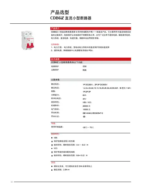
产品选型CDB6iZ直流小型断路器CDB6iZ小型断路器具有以下功能主要参数短路保护过载保护额定电压:额定电流:极数:分断能力:耐冲击电压:脱扣特性:机械寿命:电气寿命:符合标准:符合认证:环境:使用环境温度:脱扣特性:Ii(B)保护短路电流较小的负载脱扣特性:瞬时脱扣范围(4.4~6.6)InIi(C)保护常规负载和配电线缆脱扣特性:瞬时脱扣范围(6.8~10.2)In安装:模块化安装,可方便地安装在DIN标准导轨上额定扭矩:2.5N·m1P DC250V;2P/3P DC500V1,2,3,4,5,6,8,10,13,16,20,25,32,40,50,63A(B型无1-6A)1P/2P/3P6KA4KVIi(B) / Ii(C)20000次10000次GB14048.2/IEC60947-2-35℃~70℃控制隔离CDB6iZ小型直流断路器是新6系列终端配电中唯一一款直流产品,它主要用作对直流线路或设备的过载保护,短路保护以及线路的不频繁转换之用。
且可广泛应用于通信电源、新能源充电桩、电力系统、直流电源、轨道交通、船舶和冶金等诸多领域。
应用举例:1、电力工程:电力系统,变电站电力系统中的直流保护系统如直流屏2、通信电源,网络数据中心电源配电系统如PDU。
技术参数接线隧道式接线端子接线能力:1~63A,适用于25mm2及以下导线接线方式如下图:安装环境接线隧道式接线端子接线端子面积:1~32A,适用于25mm2及以下导线 40~63A,适用于35mm2及以下导线模块化安装,可方便地安装在DIN标准导轨上额定扭矩:32A及以下,2.5N40-63A,3.5N使用温度:-25℃~60℃。
新DZ20LE系列剩余电流动作断路器使用说明书符合标准:GB/T14048.2IEC60947-2□安装、使用产品前,请仔细阅读使用说明书,并妥善保管、备用。
新DZ20LE 系列剩余电流动作断路器安全告知在安装、操作、运行、维护、检查称漏电断路器)之前,请务必认真阅读本说明书,并按照说明书上的内容准确安装、使用本产品。
剩余电流动作断路器(以下简●●使用中,严禁触摸导电部位;●维护与保养时,必须确保产品不带电;●严禁用短路的办法来测试产品。
严禁湿手操作漏电断路器;危 险:注 意:●安装、维护与保养时,应由具有专业资格的人员操作;●产品只适用于三相系统电源;●产品的各项特性出厂时已整定,使用中不能自行拆装或随意调节;●使用前请确认产品工作电压、额定电流、频率及特性是否符合工作要求;●为防止相间短路,应对接线端裸露导线或铜母线进行绝缘处理;●如需测试绝缘电阻或工频耐压,必须先将电流回路之间的电子元件断开,否则将损坏产品性能;●对少接线、错接线,本产品不能起到漏电保护作用;●如需选购附件,请选用本公司所提供的配套附件,以保证质量,如用户使用非本公司附件而产生的一切不良后果,本公司概不负责;●装有欠压脱扣器的产品,产品合闸前欠压脱扣器必须先通额定电压;●如果产品在开箱时有破损或异常响声,应立即停止使用并联系供应商;●产品报废时,请做好产品废弃物处理,谢谢您的合作。
认识新DZ20LE 漏电断路器●装箱单产品本机合格证附件袋(包括接线鼻)附件袋(包括联结板)相间隔板1234台张袋袋片11113序号名 称单位数量备 注DZ20LE-160、250产品默认标配,可取消配置DZ20LE-400、630产品默认标配,可取消配置内置于内盒盒贴1、电源端2安装孔、3公司商标、4试验按钮、5、参考标准6、产品型号(透明盖增加 T 表示)7、技术参数8公司名称、9额定剩余电流调节开关、10漏电测试按钮、11、负载端1 2 3 4 5 6 7 8 9 10 11DZ20LE -160T /43002BIn 160A0 ~● 面板介绍DZ20LE-160DZ20LE-250DZ20LE-400DZ20LE-630型 号额定电流InA额定短路分断能力kA (有效值)Ics 壳架等级的最大额定电流值 AIcu 50、63、80、100、125、140、160125、160、180、200、225、250200、225、250、315、350、400400、500、63016025040063068101012152020表1 漏电断路器的主要技术参数正常使用、安装及运输条件● 正常使用、安装条件(1) 周围空气温度不高于+40℃,不低于-5℃24小时的平均值不超过+35℃;(2) 安装地点的海拔不超过2000m ;(3) 大气的相对湿度在周围最高温度+40℃时不超过50%,在较低温度下可以有 较高的相对湿度,例如20℃时的90%,对于因温度变化偶尔产生的凝露,应 采取防护措施;(4) 安装位置应垂直,各方向的倾斜度不超过5°;(5) 安装在无冲击振动及无雨雪侵袭的地方;(6) 污染等级:3级;(7) 安装类别:Ⅲ类。
技术参数
额定电流:1,2,3,4,5,6,8,10,13 ,16,20,25,32,40,50,63 A 额定工作电压:230/400V AC
分断能力
符合标准:IEC60898-1 / GB10963.1
符合认证:CCC,RoHS 认证
脱扣特性
B型曲线
保护短路电流较小的负载(如电源、长电缆等)脱扣特性:瞬时脱扣范围 (3~5) In
C型曲线
保护常规负载和配电线缆
脱扣特性:瞬时脱扣范围 (5~10) In
D型曲线
保护起动电流大的冲击性负荷 (如变压器等)
脱扣特性:瞬时脱扣范围 (10~14) In
3
6
10
16
20
25
32
40
50
63
1
3
6
10
16
20
25
32
40
50
63
1
3
6
10
16
20
25
32
40
50
63
1
3
6
10
16
20
25
32
40
50
63
DZ47N1B3
DZ47N1B6
DZ47N1B10
DZ47N1B16
DZ47N1B20
DZ47N1B25
DZ47N1B32
DZ47N1B40
DZ47L1B50
DZ47L1B63
DZ47N2B1
DZ47N2B3
DZ47N2B6
DZ47N2B10
DZ47N2B16
DZ47N2B20
DZ47N2B25
DZ47N2B32
DZ47N2B40
DZ47L2B50
DZ47L2B63
DZ47N3B1
DZ47N3B3
DZ47N3B6
DZ47N3B10
DZ47N3B16
DZ47N3B20
DZ47N3B25
DZ47N3B32
DZ47N3B40
DZ47L3B50
DZ47L3B63
DZ47N4B1
DZ47N4B3
DZ47N4B6
DZ47N4B10
DZ47N4B16
DZ47N4B20
DZ47N4B25
DZ47N4B32
DZ47N4B40
DZ47L4B50
DZ47L4B63
18
18
18
18
18
18
18
18
18
18
36
36
36
36
36
36
36
36
36
36
36
54
54
54
54
54
54
54
54
54
54
54
72
72
72
72
72
72
72
72
72
72
72
2P
3P
4P
DZ47N1C3
DZ47N1C6
DZ47N1C10
DZ47N1C16
DZ47N1C20
DZ47N1C25
DZ47N1C32
DZ47N1C40
DZ47L1C50
DZ47L1C63
DZ47N2C1
DZ47N2C3
DZ47N2C6
DZ47N2C10
DZ47N2C16
DZ47N2C20
DZ47N2C25
DZ47N2C32
DZ47N2C40
DZ47L2C50
DZ47L2C63
DZ47N3C1
DZ47N3C3
DZ47N3C6
DZ47N3C10
DZ47N3C16
DZ47N3C20
DZ47N3C25
DZ47N3C32
DZ47N3C40
DZ47L3C50
DZ47L3C63
DZ47N4C1
DZ47N4C3
DZ47N4C6
DZ47N4C10
DZ47N4C16
DZ47N4C20
DZ47N4C25
DZ47N4C32
DZ47N4C40
DZ47L4C50
DZ47L4C63
DZ47L1D3
DZ47L1D6
DZ47L1D10
DZ47L1D16
DZ47L1D20
DZ47L1D25
DZ47L1D32
DZ47L1D40
DZ47L1D50
DZ47L1D63
DZ47L2D1
DZ47L2D3
DZ47L2D6
DZ47L2D10
DZ47L2D16
DZ47L2D20
DZ47L2D25
DZ47L2D32
DZ47L2D40
DZ47L2D50
DZ47L2D63
DZ47L3D1
DZ47L3D3
DZ47L3D6
DZ47L3D10
DZ47L3D16
DZ47L3D20
DZ47L3D25
DZ47L3D32
DZ47L3D40
DZ47L3D50
DZ47L3D63
DZ47L4D1
DZ47L4D3
DZ47L4D6
DZ47L4D10
DZ47L4D16
DZ47L4D20
DZ47L4D25
DZ47L4D32
DZ47L4D40
DZ47L4D50
DZ47L4D63订货信息
注:1.电流规格为2、4、5、8、13 A产品,接受定制,订货号参考编码规则
2.若订购符合RoHS认证产品,请在订货号后加“R”
小型断路器附件DZ47
与断路器拼装示意图
当得到信号后,触发与之拼装的断路器脱扣
辅助触头基本形式:一常开,一常闭
接线能力:1-4mm2导线
OF、SD须拼装在断路器左侧,每只断路器左侧仅能拼装一个附件
MX+OF拼装在断路器右侧,每只断路器右侧只能拼装一个附件
订货信息
OF
MX+OF
9
9
18
18
18
18
DZ47OF
DZ47SD
DZ47MX24
DZ47MX48
DZ47MX110
DZ47MX230
AC/DC12~24V
AC/DC24~48V
AC110~127V
AC230~400V
DZ47/CDB6系列—OF辅助触头/SD报警触头DZ47/CDB6系列—MX+OF 分励脱扣器
小型断路器及隔离开关
CDB6s 标准断路器
DZ47标准断路器
CDB2大电流断路器
CDB2系列—OF辅助触头/MX+OF分励脱扣器
CDB5隔离开关
小型断路器及隔离开关
CDB6s标准断路器/DZ47标准断路器/DZ47LE标准漏电保护断路器
CDB3“相线+中性线”断路器/CDB3LE“相线+中性线”漏电保护断路器。