OPK Preinstall Guide - Touch Pack for Windows 7
- 格式:docx
- 大小:34.10 KB
- 文档页数:8

ContentsUSRP RIO device Getting Started Guide. . . . . . . . . . . . . . . . . . . . . . . . . . . . . . . . . . . . . . . . . . . 4 Verifying the System Requirements. . . . . . . . . . . . . . . . . . . . . . . . . . . . . . . . . . . . . . . . . . . . 4 Unpacking the Kit. . . . . . . . . . . . . . . . . . . . . . . . . . . . . . . . . . . . . . . . . . . . . . . . . . . . . . . . . . . . 4 Verifying the Kit Contents. . . . . . . . . . . . . . . . . . . . . . . . . . . . . . . . . . . . . . . . . . . . . . . . 5 Environmental Guidelines. . . . . . . . . . . . . . . . . . . . . . . . . . . . . . . . . . . . . . . . . . . . . . . . . . . . 6 Environmental Characteristics. . . . . . . . . . . . . . . . . . . . . . . . . . . . . . . . . . . . . . . . . . . 7 Installing the Software. . . . . . . . . . . . . . . . . . . . . . . . . . . . . . . . . . . . . . . . . . . . . . . . . . . . . . . 7 Installing the Software Using NI Package Manager. . . . . . . . . . . . . . . . . . . . . . . . . . 7Installing the Software Using the Driver Download Page. . . . . . . . . . . . . . . . . . . . 8 Installing the Device. . . . . . . . . . . . . . . . . . . . . . . . . . . . . . . . . . . . . . . . . . . . . . . . . . . . . . . . . . 8 Connecting the Device. . . . . . . . . . . . . . . . . . . . . . . . . . . . . . . . . . . . . . . . . . . . . . . . . . . 8Powering on the Device. . . . . . . . . . . . . . . . . . . . . . . . . . . . . . . . . . . . . . . . . . . . . . . . 10Synchronizing Multiple Devices (Optional). . . . . . . . . . . . . . . . . . . . . . . . . . . . . . . 10Preparing the USRP-2945 for LO Sharing (Optional). . . . . . . . . . . . . . . . . . . . . . . 11Preparing the USRP-2945 for LO Re-Import (Optional). . . . . . . . . . . . . . . . . . . . . 12 Programming the Device. . . . . . . . . . . . . . . . . . . . . . . . . . . . . . . . . . . . . . . . . . . . . . . . . . . . 13 NI-USRP Instrument Driver. . . . . . . . . . . . . . . . . . . . . . . . . . . . . . . . . . . . . . . . . . . . . 13Verifying the Device Connection (Optional). . . . . . . . . . . . . . . . . . . . . . . . . . . . . . . 16 Troubleshooting. . . . . . . . . . . . . . . . . . . . . . . . . . . . . . . . . . . . . . . . . . . . . . . . . . . . . . . . . . . . 17 Why Doesn't the Device Power On?. . . . . . . . . . . . . . . . . . . . . . . . . . . . . . . . . . . . . . 17Why Doesn't the USRP Device Appear in the NI-USRP Configuration Utility?. . 18Why Does USRP2 Appear Instead of the USRP Device in the NI-USRPConfiguration Utility?. . . . . . . . . . . . . . . . . . . . . . . . . . . . . . . . . . . . . . . . . . . . . . . . . . 18Should I Update Device Firmware and FPGA Images?. . . . . . . . . . . . . . . . . . . . . . 18Why Do I Receive an Enumeration Error?. . . . . . . . . . . . . . . . . . . . . . . . . . . . . . . . . 18Why Don't NI-USRP Examples Appear in the NI Example Finder in LabVIEW?. 19 Front Panels, Back Panels, and Connectors. . . . . . . . . . . . . . . . . . . . . . . . . . . . . . . . . . . . 19 Direct Connections to the Device. . . . . . . . . . . . . . . . . . . . . . . . . . . . . . . . . . . . . . . . 19USRP-2940 Front Panel, Back Panel, and LEDs. . . . . . . . . . . . . . . . . . . . . . . . . . . . 20USRP-2942 Front Panel, Back Panel, and LEDs. . . . . . . . . . . . . . . . . . . . . . . . . . . . 23USRP-2943 Front Panel, Back Panel, and LEDs. . . . . . . . . . . . . . . . . . . . . . . . . . . . 26USRP-2944 Front Panel, Back Panel, and LEDs. . . . . . . . . . . . . . . . . . . . . . . . . . . . 29USRP-2945 Front Panel, Back Panel, and LEDs. . . . . . . . . . . . . . . . . . . . . . . . . . . . 322GPIO Connector. . . . . . . . . . . . . . . . . . . . . . . . . . . . . . . . . . . . . . . . . . . . . . . . . . . . . . . 35 Where to Go Next. . . . . . . . . . . . . . . . . . . . . . . . . . . . . . . . . . . . . . . . . . . . . . . . . . . . . . . . . . . 35 NI Services. . . . . . . . . . . . . . . . . . . . . . . . . . . . . . . . . . . . . . . . . . . . . . . . . . . . . . . . . . . . . . . . . 36© National Instruments3USRP RIO device Getting Started GuideThis document explains how to install, configure, and test the following USRP RIO devices:■ USRP-2940 Software Defined Radio Reconfigurable Device■ USRP-2942 Software Defined Radio Reconfigurable Device■ USRP-2943 Software Defined Radio Reconfigurable Device■ USRP-2944 Software Defined Radio Reconfigurable Device■ USRP-2945 Software Defined Radio Reconfigurable DeviceThe USRP RIO device can send and/or receive signals for use in various communications applications. The device ships with the NI-USRP instrument driver, which you can use to program the device.Verifying the System RequirementsTo use the NI-USRP instrument driver, your system must meet certain requirements. Refer to the product readme, which is available online on the driver software download page or at /manuals, for more information about minimum system requirements, recommended system, and supported application development environments (ADEs).Unpacking the Kit1.Touch the antistatic package to a metal part of the computer chassis.2.Remove the device from the package and inspect the device for loosecomponents or any other sign of damage.43.Unpack any other items and documentation from the kit.Store the device in the antistatic package when the device is not in use.Verifying the Kit ContentsFigure 1. Kit ContentsRP RIO Device2.SMA Driver Bit (USRP-2945 Only)3.Getting Started Guide (This Document) and Safety, Environmental, and Regulatory Information Document4.SMA (m)-to-SMA (m) Cable5.30 dB SMA Attenuator (Not Included with USRP-2945)© National Instruments 5Other Required Item(s)In addition to the kit contents, you must provide the following additional item(s):■An MXI Express interface card. You can purchase an MXI Express interface kitfor your USRP RIO device, which contains an MXI Express interface card, at.Optional Items■ LabVIEW Modulation Toolkit (MT), available for download at /downloads and included in LabVIEW Communications System Design Suite,which includes MT VIs and functions, examples, and documentation■ LabVIEW Digital Filter Design Toolkit, available for download at /downloads and included in LabVIEW Communications System Design Suite■ LabVIEW MathScript RT Module, available for download at /downloads■Additional SMA (m)-to-SMA (m) cables to use the REF IN and PPS IN signals■ PCIe - MXI Express Interface Kit for USRP RIO to connect to a desktopcomputer■ ExpressCard Slot - MXI Express Interface Kit for USRP RIO to connect to alaptop computer■ PXIe - MXI Express Interface Kit for USRP RIO to connect to a PXI Expresschassis■ CDA-2990 Clock Distribution Device for synchronizing multiple devices■ CPS-8910 Switch Device for PCI Express for large multiple-input, multiple-output (MIMO) expansion configurations■ PXI-5691 RF Amplifier for local oscillator (LO) re-import with the USRP-29456Environmental GuidelinesEnvironmental CharacteristicsOperating temperature0 °C to 45 °COperating humidity10% to 90% relative humidity, noncondensingPollution Degree2Maximum altitude2,000 m (800 mbar) (at 25 °C ambient temperature) Installing the SoftwareYou must be an Administrator to install NI software on your computer.1.Install an application development environment (ADE), such as LabVIEW orLabVIEW Communications System Design Suite.2.Follow the instructions below that correspond with the ADE that you installed. Installing the Software Using NI Package ManagerEnsure that you have installed the latest version of NI Package Manager. To accessthe download page for NI Package Manager, go to /info and enter info code NIPMDownload.1.To install the latest NI-USRP instrument driver, open NI Package Manager.2.On the BROWSE PRODUCTS tab, click Drivers to display all available drivers.© National Instruments73.Select NI-USRP and click INSTALL.4.Follow the instructions in the installation prompts.Related information■Install NXGInstalling the Software Using the Driver Download Page1.Visit /info and enter the Info Code usrpdriver to access the driverdownload page for all versions of NI-USRP software.2.Download a version of NI-USRP driver software.3.Follow the instructions in the installation prompts.4.When the installer completes, select Shut Down in the dialog box thatprompts you to restart, shut down, or restart later.Installing the DeviceInstall all the software you plan to use before you install the hardware. Ensure that the USRP RIO device and computer are off before installing.Connect any additional attachments required for your project to the front panel terminals of the USRP RIO device.8Connecting the DeviceThe USRP RIO device must be connected either to a desktop computer or a laptop computer.Connecting to a Desktop ComputerConnect the USRP RIO device to a desktop computer using an MXI Express interface kit.1.Insert the MXI card into your computer according to the installationinstructions in the Hardware Installation section of the Set Up Your MXI™Express ×4 System document included in your MXI Express interface kit.2.Connect the MXI device to the USRP RIO device using the PCIe cable includedin your MXI Express interface kit.Connecting to a Laptop ComputerConnect the USRP RIO device to a laptop computer using the ExpressCard-8360 for USRP Device for PXI Remote Control.1.Touch the ExpressCard-8360 for USRP and outer metal case of the USRP RIOdevice simultaneously.2.Connect the included cable to the to the ExpressCard-8360 for USRP.3.Plug the ExpressCard-8360 for USRP into an available ExpressCard slot.The completed hardware setup is shown in the following figure.© National Instruments9Figure 2. Connecting the Device with a Laptop Connectivity Kit1.Cable Included with ExpressCard Interface Kit2.ExpressCard-8360 for USRP3.ExpressCard Slotptop ComputerPowering on the Device1.Connect the power supply to the USRP RIO device.2.Plug the power supply into a wall outlet. Press the power button on the frontof your device.3.Power on the chassis and network switch.Synchronizing Multiple Devices (Optional)To set up a higher channel-count system, you can synchronize two or more USRP RIO devices so that they share clock and pulse per second (PPS) signals.10Ensure that all hardware is set up as previously described.1.Connect the REF IN port of the USRP RIO device to the first 10 MHz OUT port ofthe CDA-2990 using a standard SMA (m)-to-SMA (m) cable.2.Connect the PPS TRIG IN port of the USRP RIO device to the PPS OUT port ofthe CDA-2990 using a standard SMA (m)-to-SMA (m) cable.3.Repeat steps 1 and 2 to synchronize additional USRP RIO devices using theadditional ports on the CDA-2990 (optional).The completed hardware setup for two USRP RIO devices is shown in thefollowing figure.Figure 3. USRP Device Synchronization Configuration1.SMA (m)-to-SMA (m) Cables2.SMA (m)-to-SMA (m) CablesPreparing the USRP-2945 for LO Sharing (Optional)Complete the following steps to prepare a single USRP-2945 device to share LOsamong all four of the device's channels.1.Connect the LO OUT 1 IF2 connector of the USRP-2945 back panel to theLO IN 0 IF2 connector of the same USRP-2945 back panel using an SMA (m)-to-SMA (m) cable.2.Connect the LO OUT 1 IF1 connector of the USRP-2945 back panel to theLO IN 0 IF1 connector of the same USRP-2945 back panel using an SMA (m)-to-SMA (m) cable.The completed hardware setup is shown in the following figure.Figure 4. USRP-2945 Single Device LO Sharing1.SMA(m)-to-SMA(m) CablesPreparing the USRP-2945 for LO Re-Import (Optional)Complete the following steps to prepare a single USRP-2945 device to exportLO OUT 1 and re-import to LO IN 1 and LO IN 0.1.Connect the LO OUT 1 IF2 connector of the USRP-2945 back panel to the INconnector of an RF power amplifier front panel using an SMA (m)-to-SMA (m) cable.2.Connect the OUT connector of the RF power amplifier to the input port of atwo-way RF power splitter using an SMA (m)-to-SMA (m) cable.3.Connect the two output ports of the RF power splitter front panel to theLO IN 0 IF2 and LO IN 1 IF2 connectors of the USRP-2945 back panel using SMA (m)-to-SMA (m) cables.4.Repeat steps 1 through 3 using a second splitter and additional cables to re-import and share the IF1 signal.The completed hardware setup is shown in the following figure.Figure 5. LO Re-Import Configuration1.RF Power AmplifierRP RIO Device3.RF Power Splitters4.SMA (m)-to-SMA (m) CablesProgramming the DeviceYou can use the NI-USRP instrument driver to create communications applications for the USRP RIO device.USRP RIO devices are LabVIEW FPGA targets, which support creating custom FPGAs and configuring the device using Instrument Design Libraries (IDLs).NI-USRP Instrument DriverThe NI-USRP instrument driver features a set of functions and properties that exercise the capabilities of the USRP RIO device, including configuration, control, and other device-specific functions.Related concepts■Refer to the NI-USRP Manual for information about using the instrument driver in your applications.Software OptionsNI provides two software options for programming the USRP RIO device: the NI-USRP API and the USRP RIO IDL.Table 1. Software OptionsNI-USRP Examples, Lessons, and Sample ProjectsNI-USRP includes several examples, lessons, and sample projects for LabVIEW, LabVIEW NXG, and LabVIEW Communications System Design Suite. They can be used individually or as components of other applications.NI-USRP examples, lessons, and sample projects are available in the following locations.Verifying the Device Connection (Optional)Complete the steps appropriate for your installed ADE to verify the device connection.Verifying the Device Connection Using LabVIEW NXG or LabVIEW Communications System Design Suite 2.1 to CurrentUse USRP Rx Continuous Async to confirm that the device receives signals and isconnected correctly to the host computer.1.Navigate to Learning » Examples » Hardware Input and Output » NI-USRP » NI-USRP.2.Select Rx Continuous Async. Click Create.3.Run USRP Rx Continuous Async.If the device is receiving signals you will see data on the front panel graphs. 4.Click STOP to conclude the test.Verifying the Device Connection Using LabVIEWRun a VI to confirm that the device transmits and/or receives signals and is connected correctly to the host computer.1.Create a sample project in LabVIEW by selecting File » Create Project »NI-USRP.2.Select the NI-USRP Simple Streaming sample project template and click Next.3.Run the appropriate streaming VI according to your USRP RIO device.display waveform data.4.Click STOP to conclude the test.TroubleshootingIf an issue persists after you complete a troubleshooting procedure, search our KnowledgeBase for additional information our technical support engineers create as they answer common user questions and resolve unexpected issues.Why Doesn't the Device Power On?If you cannot power on the device, complete the following steps.■Verify that the device is connected to the power supply.■Verify that the power supply is functional.■Verify that the power switch on the front of the device is engaged.Why Doesn't the USRP Device Appear in the NI-USRP Configuration Utility?Check the connection between the USRP RIO device and the computer. Ensure that the USRP RIO device is powered on and connected to a computer before you power on the computer.Why Does USRP2 Appear Instead of the USRP Device in the NI-USRP Configuration Utility?■An incorrect IP address on the computer may cause this error. Check the IP address and run the NI-USRP Configuration Utility again.■An old FPGA or firmware image on the device may also cause this error.Upgrade the FPGA and firmware using the NI-USRP Configuration Utility. Should I Update Device Firmware and FPGA Images?Your device ships with firmware and FPGA images compatible with the NI-USRP driver software. You may need to update the device for compatibility with the latest version of the software.The driver software media also includes the NI-USRP Configuration Utility, which you can use to update the devices.Why Do I Receive an Enumeration Error?If you are using a desktop computer with the NI-USRP instrument driver installed, it is possible that there is a compatibility issue between your computer and the PCIe card. Complete the following steps to confirm this issue and resolve it.1.Navigate to Start » Device Manager to confirm the issue by verifying that PCIData Acquisition and Signal Processing Device/Controller appears in Device Manager and that your USRP RIO device does not.If you cannot confirm this, then the issue is not likely caused by acompatibility problem between your computer and the PCIe card. Contact NI or visit /support2.Install the latest BIOS Compatibility software.3.Restart your computer.plete the steps appropriate for your installed ADE in Verifying the DeviceConnection. Repeat step 1 and observe if the outcome has changed. If youstill receive an Enumeration Error, continue to step 5.5.Power off your computer and remove the MXI card.6.Toggle switch 1.7.Reinstall the MXI card and power on your computer.8.Repeat step 4. If nothing has changed, continue to step 7.9.Uninstall the BIOS Compatibility software. Restart your computer.10.Repeat step 4.If trouble persists, contact NI or visit /support.Why Don't NI-USRP Examples Appear in the NI Example Finder in LabVIEW?NI-USRP does not install examples into the NI Example Finder.Related concepts■NI-USRP Examples, Lessons, and Sample ProjectsDirect Connections to the DeviceThe USRP RIO device is a precision RF instrument that is sensitive to ESD and transients. Ensure you take the following precautions when making direct connections to the USRP RIO device to avoid damaging the device.■ Ensure you are properly grounded when manipulating cables or antennas connected to the USRP RIO device TX 1 RX 1, RX 1, or RX 2 connector.■ If you are using nonisolated devices, such as a nonisolated RF antenna,ensure the devices are maintained in a static-free environment.■If you are using an active device, such as a preamplifier or switch routed to the USRP RIO device TX 1 RX 1, RX 1, or RX 2 connector, ensure that the device cannot generate signal transients greater than the RF and DC specifications of the USRP RIO device TX 1 RX 1, RX 1, or RX 2 connector.USRP-2940 Front Panel, Back Panel, and LEDsFront PanelTable 8. Connector DescriptionsTable 9. LED Descriptions The LED indications described in the following table occur only when you use the NI-USRP API with the default FPGA image. When you use LabVIEW FPGA, you customize the LED indications.Back PanelTable 10. Connector DescriptionsUSRP-2942 Front Panel, Back Panel, and LEDs Front PanelTable 8. Connector DescriptionsTable 9. LED Descriptions Back PanelTable 10. Connector DescriptionsUSRP-2943 Front Panel, Back Panel, and LEDs Front PanelTable 8. Connector DescriptionsTable 9. LED Descriptions The LED indications described in the following table occur only when you use the NI-USRP API with the default FPGA image. When you use LabVIEW FPGA, you customize the LED indications.Back Panel.Table 10. Connector DescriptionsUSRP-2944 Front Panel, Back Panel, and LEDs Front PanelTable 11. Connector DescriptionsTable 12. LED IndicatorsBack PanelTable 13. Connector Descriptions© National Instruments31USRP-2945 Front Panel, Back Panel, and LEDs Front PanelTable 14. Connector Descriptions32Table 15. LED IndicatorsBack Panel© National Instruments3334Table 16. Connector DescriptionsGPIO ConnectorTable 17. GPIO Connector Pin Assignments© National Instruments35Where to Go NextRefer to the following figure for information about other product tasks andNI ServicesVisit /support to find support resources including documentation,downloads, and troubleshooting and application development self-help such as tutorials and examples.Visit /services to learn about NI service offerings such as calibration options, repair, and replacement.Visit /register to register your NI product. Product registration facilitatestechnical support and ensures that you receive important information updates from NI.NI corporate headquarters is located at 11500 N Mopac Expwy, Austin, TX,78759-3504, USA.36© 2022 National Instruments Corporation.。
Open sankor使用说明
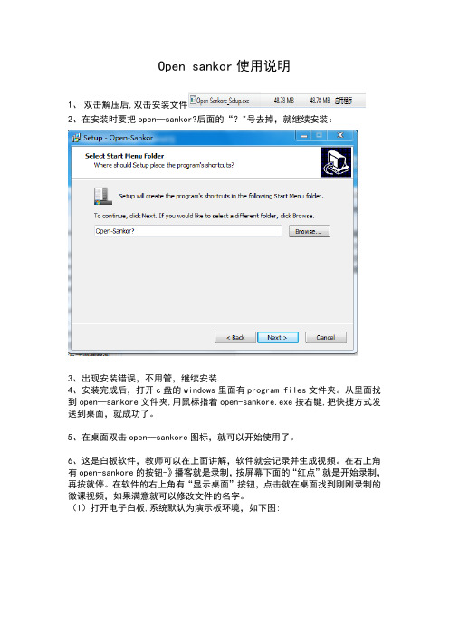
1、双击解压后,双击安装文件
2、在安装时要把open—sankor?后面的“?"号去掉,就继续安装:
3、出现安装错误,不用管,继续安装.
4、安装完成后,打开c盘的windows里面有program files文件夹。
从里面找到open—sankore文件夹,用鼠标指着open-sankore.exe按右键,把快捷方式发送到桌面,就成功了。
5、在桌面双击open—sankore图标,就可以开始使用了。
6、这是白板软件,教师可以在上面讲解,软件就会记录并生成视频。
在右上角有open-sankore的按钮-》播客就是录制,按屏幕下面的“红点”就是开始录制,再按就停。
在软件的右上角有“显示桌面”按钮,点击就在桌面找到刚刚录制的微课视频,如果满意就可以修改文件的名字。
(1)打开电子白板,系统默认为演示板环境,如下图:
在屏幕的中间区域,可以实现白板书写的功能,并且可以根据需求改变笔的颜色和粗细
(2)单击’ 图标,在屏幕下方会出现工具栏,如下图:
再次单击则隐藏该工具栏。
(3)屏幕左侧可以设置页面标题以及其他索引,如下图:
(4)单击右上角的图标,可以打开搜索引擎
(5)单击图标,查看已经保存的演示文档,或者实现新建文档等功能,如下图:
(6)单击图标,系统进入后台运行模式,屏幕左侧会出现一个工具栏,若要返回白板界面,单击即可。
(7)单击图标,如下图:
单击‘播客’,屏幕上出现录制按钮,即可开始录制屏幕,如下图:
(8)屏幕右侧有丰富的资源可供放入演示板进行二次编辑使用,如下图:。

SP1 ACTION CAMAvailable Colors:u l a t ed.SP1SPECIFICATIONSSP1Effective Image Sensor Pixels14.24 Megapixels T otal Image Sensor Pixels15.31 Megapixels [1/2.3” CMOS]LensFocal Length 3.0 mm [ 35mm film equivalent ][16.8 mm] F numberF2.8 Lens Construction6 groups 6 elements Optical ZoomFixed Focus, 160 DegreeFocusing RangeNormal: 60 cm — ∞Field of View (FOV)Ultra Wide, Medium, Narrow, Water Ring Anti-HandshakeElectronic Image Stabilization Number of Recording PixelsStill Image(4:3) 14MP: 4320x3240, 5MP: 2592x1944, (16:9) 10MP: 4320x2432 Movie1920x1080 (30fps), 1280x960 (50fps), 1280x960 (30fps), 1280x720 (60fps), 1280x720 (30fps), 848x480 (60fps)High-Speed Movie: 848x480 (120fps)Image CompressionBest File FormatStill ImageExif 2.3 (JPEG) MovieMovie Format: MOV (H.264), Audio: Linear PCM (Stereo)Shooting ModesAuto Detection FeaturesFace WaterproofUp to 32 ft. / 10m ShockproofUp to 6.5 ft. / 2m DustproofEquivalent to JIS/IEC (IP6X)Freezeproof14°F / –10°C WirelessYes LCD Display1.5 inch (115K Pixels)ISO SensitivityAuto (100 - 800)AF MethodSingle AF, Multi-AF (TTL 9-point), Face Detection Exposure Metering MethodArtificial Intelligence AE (AiAE), Face AE Exposure Control MethodProgram AE (AE-Lock Available)Burst ModeApprox. 10fps (Full Resolution)Playback ModesSingle White Balance ControlAuto (AWB), Daylight, Cloudy, Flourescent, Underwater Recording MediaInternal Memory: Approx. 100MBMicro SD/Micro SDHC Card (Up to 32GB Support) [MMC Card not supported]Other FeaturesMulti-Language Support (27 Languages)JacksUSB 2.0 (Micro 5 pin USB), HDMI (Type D)PowerRechargeable Li-ion Battery LB-080, 3.6V 1250mAh, In-Camera Charging Shooting CapabilityApprox. 350 Shots (Based on CIPA Standards); Approx. 130 min. for Video (@1080p/30fps) (Battery Performance)Operation EnvironmentT emperature: 14° – 104°F / –10° – 40°C, Humidity: 0 – 90%Dimensions (WxHxD)Approx. 3.33 x 2.02 x 1.55 in / 84.7 x 51.4 x 39.5 mm (Based on CIPA Standards)WeightApprox. 5.4 oz. / 155g (Body Only)Supplied AccessoriesRechargeable Li-ion Battery, AC Adapter, USB Cable, CD-ROM, Quick Start Guide, Warranty Card, Service Card, Standard Lens Cover, Underwater Lens CoverJK Imaging, Ltd.1411 W. 190th Street, Suite 550Gardena, CA 90248© 2013 JK Imaging, Ltd. The Kodak trademark and trade dress are used under license from Kodak.All information contained in this document is subject to change without notice.Document Number/Sequence: U.DIS.0012.1114.en.01T。


3.1 Connect the parts3.2 Wi-Fi antenna3.3Camera module (optional)PICO-PI-IMX7Quickstart Guide3 Installation InstructionsThis installation guide will help you to assemble your development kit using step-by-step instructions to make sure all parts (development board, Wi-Fi antenna, camera module and display) are working.Please follow the steps below to properly install the Wi-Fi antenna.Step 1: Prepare Wi-Fi antenna, extender cable and development board.Step 2: Locate the round antenna pin on the development board. Make sure the connector is aligned with the pin. Press the small round connector at the end of the extender cable onto this pin. You will need to press down until you hear a click sound.Step 3: Screw the extender cable into the base of the Wi-Fi antenna.Connect the parts in the following order. Please note that some versions of the PICO-PI-IMX7 evaluation kit do not include the camera, multi-touch display, and/or cardboard stand.Tips: Do not power your board during the installation process.Step 4: Swivel the retaining clip back down to hold the FPC cable in place.Steps 5 and 6: Repeat these same steps with the other end of the cable and the connector on the board.Tips: After installation remove the protective blue film from the camera lens.INNOVATORS OF TECHNOLOGY2 Dimensions1 Safety PrecautionsThank you for purchasing a T echNexion PICO series evaluation kit based on NXP i.MX7 Dual applications processor. This installation guide will be helpful in the installation, wiring and inspection of your T echNexion evaluation kit. Before using the product, please read this guide to ensure correct use. You should thoroughly understand all safety precautions before proceeding with the installation, wiring, and operation. Place this instruction sheet in a safe location for future reference.• Keep the device dry. Precipitation, humidity, and all types of liquids or moisture can contain minerals that will corrode electronic circuits. If your device does get wet, allow it to dry completely.• Do not use or store the device in dusty or dirty areas. Its parts and electronic components can be damaged.• Do not store the device in hot areas. High temperatures can shorten the life of electronic devices, damage batteries, and warp or melt certain plastics.• Do not store the device in cold areas. When the device returns to its normal temperature, moisture can form inside the device and damage electronic circuit boards.• This product is designed for specific applications and needs to be installed by qualified personnel.• Do not drop, knock, or shake the device. Rough handling can break internal circuit boards and fine mechanics.• Do not paint the device. Paint can clog the parts and prevent proper operation.• Unauthorized modifications or attachments could damage the device and may violate regulations governing radio devices.• Do not touch any internal or exposed parts of the device as electrical shock may result.• Do not open the device while power is on. Otherwise electrical shock may result.• Do not use harsh chemicals, cleaning solvents, or strong detergents to clean the device.• Be sure the ventilation holes are not obstructed during operation. Otherwise malfunction may result due to bad ventilation or overheating.These suggestions apply equally to your device, battery, charger, or any enhancement. If any device is not working properly, take it to the nearest authorized service facility for service.• Make sure that the available power source matches the required input power of the device. Failure to observe this caution may result in electric shock or fire.1.1 Storage and Installation1.2 Wiring1.3 Maintenance and Inspection!Unit : mm123.5 Display (optional)3.6 Cardboard stand (optional)5 External ConnectorsTime to set up the cardboard stand. It only takes a few minutes.Step 1: Separate the shapes from the cardboard.Step 2: Bend and fold the pieces along their scored lines.Step 3: Turn the stand upside down and insert the lettered tabs into the matching lettered slots.Step 4: Turn the stand back and lift the tabs.3.7 Final steps (optional)Now your kit is almost assembled.Step 1: Insert the camera through the opening on the top side. Loop it around the back and to the top. Press the camera into the square opening. Reattach the FPC cable to the camera module.Step 2: Adjust the antenna to a 90-degree angle. Insert it into the circular portion of the cutout and push it back until the joint is flush with the stand. Now push the antenna down for a snug fit. Reattach the extender cable to the antenna.Step 3: Hold the display and board in front of the display and development board opening. Lower the display and board in position and gently press the edges into the stand. Connect the USB Type-C cable to power up the evaluation kit.T op side view:Rear side view:• All Rights Reserved. No part of this document may be photocopied, reproduced, stored in a retrieval system, or transmitted, in any form or by any means whether, electronic, mechanical, or otherwise without the prior written permission of T echNexion Ltd.• No warranty of accuracy is given concerning the contents of the information contained in this publication. T o the extent permitted by law no liability (including liability to any person by reason of negligence) will be accepted by T echNexion Ltd., its subsidiaries or employees for any direct or indirect loss or damage caused by omissions from or inaccuracies in this document.• TechNexion Ltd. reserves the right to change details in this publication without notice. Please download the most updated version at: https:///support/download-center/Phone: +886-2-82273585 Web: 16F-5, No. 736, Zhongzheng Road, ZhongHe District, 23511, New Taipei City, Taiwan © 2001-2019 T echNexion Ltd.2020-12-156 Software InstallationThe unit is preloaded with software that can download and install a selection of OS images over hardwired network. Simply connect a network to the unit through the LAN RJ45 connector and power it up, then follow the steps on the screen to load the software. Local proxies will interfere with this process. For more information, go to our Knowledge Base at: https:///support/knowledge-base/Description No. No. Description 123456121314157891011Reset buttonUSB OTG (Type-C) connector 3.5mm jack audio out LAN RJ45 connectorJP2 mikroBUS connector USB Host connectorJP1 mikroBUS connector Console connectorIS2 Bus jumper Boot pin header40-pin Expansion headerWiFi antenna MHF4 connector Touch connectorMIPI Display connector MIPI Camera connector3414BACE FDPlease follow the steps below to properly install the VOICEHAT.3.4 VOICEHAT (optional)Step 1: Locate four standoff holes, insert screws into the holes and screw standoffs on top. Then locate three module holes, insert screws into the holes. Place and tighten nuts on top.Step 2: Insert slowly the module and gently press into the development board to secure it.Step 3: Connect both speakers to the VOICEHAT. Make sure the speaker cables exit on the left side.Step 4: Align the 40-pin female connector next to the 40-pin male connector on the development board and gently press the connector on the back of the VOICEHAT onto the connector on the board. Then secure it with screws.4 Pin Definition4.1 IMX7-EMMC BOOT Jumper Settings4.2 I²S Bus SettingsSD(Module)Jumper #eMMC Serial DownloaderJumper 1Jumper 1Jumper 22-4 , 3-52-4 , 1-34-6 , 1-32-4 , 1-32-4 , 3-54-6 , 3-5123456121110987135246135246Jumper #I²S1I²S31-24-58-911-122-35-67-810-11Jumper 1Jumper 2Jumper 3Jumper 4Jumper 2。

飞利浦写软件、解PCK全攻略飞利浦手机很多手机如859,855,825,826,9@9C,820,620,630等已进入维修期,出现如开机定屏,不定时死机等故障,此类故障大多由于CPU虚焊和软件问题引起,但当我们处理软件故障时,用编程器把从另外一台好机读出的资料复制到有软件故障的故障机,可开机但又出现PCK锁,怎么办呢?本文就针对用飞利浦6353,6354,6357CPU的飞利浦手机写软件,解PCK的问题,将本人的使用方法与各位分享,不当之处,还望多多指正!方法和步骤:1:用128或免拆把资料写到手机字库(48资料和免拆资料不能通用,但可以用UP128互转。
)2:解PCK写字库工具:1:UP128/192/256/1024;可备份全字库和写全字库,对于一些不联机的手机要用此方法,优点是安全快捷,(如9A9++用UP128写字库)1)打开128程序,选型号M36DR432A,打开PHILIPS 9@9++资料,2)按编程按钮,待编程完成即可。
3)写完后手机就可以开机了,最后进行解PCK操作2:DWLDEV和DOWN5.0;Philips公司原厂刷机工具,免狗,用普通数据线即可,可以写全字库、空字库,采用块擦除的方式,即:边擦除边写入!DWLDEV和DOWN5.0没有解PCK锁功能,写完字库要解PCK锁!使用方法:(以PHILIPS 9@9++为例)1:运行软件后,如下图,先设置好端口,在select a project中选择“5087-RAM 16bits(X16,X16WAP,V21,WAD,X38,Z10)”,KEEP LOSE选择开关置于LOSE端 OFF ON选择开关置于ON端。
2:单击select a file,然后选择正确的文件,单击打开3:单击START,弹出下图界面,然后迅速按手机开机键。
4:如下图,软件自动读出手机字库型号,然后将资料写入手机。
5:大约几分钟字库写完后软件弹出下图界面,写完后手机就可以开机了,最后进行解PCK操作。
罗技演示软件Mac 静默安装指南简介罗技演示软件让您可以配置和控制 Spotlight无线演示器,并可为多用户进行远程静默安装。
下载罗技演示软件,请点击此处。
安装罗技演示软件及其文件有多种方法,例如,可通过 Apple Remote Desktop或众多商用 IT 软件包中的任何一款进行安装。
几种方法的思路基本相同:使用 SSH 远程访问系统登录到目标 Macintosh,下载安装程序包,然后使用适当的参数执行。
示例以下是带有注释的示例脚本:1. 将 zip 文件复制到目标系统,并将其放置于临时位置:scp LogiPresentation_Silent_Installer_1.40.62.zip admin@target:/Users/Shared/L ogiPresentation_Silent_Installer_1.40.62.zip2. 需要输入管理员用户密码:admin_password3. 登录到目标系统以执行安装程序:ssh admin@target4. 再次输入管理员用户密码:admin_password5. 切换到上一步中放置安装程序的目录:cd /Users/Shared6. 解压缩保存的文件以获取安装程序包:unzip LogiPresentation_Silent_Installer_1.40.62.zip7. 运行安装程序。
此操作必须以 root 权限完成:sudo "/Users/Shared/LogiPresentation SilentInstaller.app/Contents/MacOS/LogiPresentation Silent Installer" --silent NO --autoupdate YES --analytics YES8. 使用管理员密码验证升级权限;admin_password9. 安装成功后,应使用以下命令删除安装程序文件:rm -rf "/Users/Shared/LogiPresentation Silent Installer.app"rm LogiPresentation_Silent_Installer_1.40.62.zip10. 最后,关闭与目标的 SSH 会话:exit注意在上述脚本序列中处理密码时需谨慎。
Quick Start GuideMXD-430 4.3" Modero X Series® Wall/Flush Mount Touch PanelOverviewThe MXD-430 4.3” Modero X Series Wall/Flush Mount Touch Panel (FG5968-15) featuresedge-to-edge capacitive touch glass with multi-touch capabilities as well as advancedtechnology empowering users to operate AV equipment seamlessly, while providing theultimate in audio and video quality. The distinctive appearance will complement even themost sophisticated meeting facilities and homes.Product SpecificationsConnector LocationsUSB peripherals (mouse, keyboard, etc.) may be connected to either of the two USBports on the rear of the device (see FIG.1). The connectors are accessible via theAccess Slot shown in FIG.2. and FIG.3.Updates to the device’s firmware can also made via the USB ports.Power via PoEPower for the MXD-430 is supplied via Power Over Ethernet (PoE), utilizing anAMX-certified, capacitive touch-compliant PoE injector such as the PS-POE-AF-TC HighPower PoE Injector (FG423-83) or other approved AMX PoE power source.The incoming Ethernet cable should be connected to the RJ45 port on the MXD-430 (FIG.2).Installing the MXD-430 Into a WallThe MXD-430 comes with a clear plastic Backbox (designed to attach the panel to moststandard wall materials. This Backbox has two locking tabs (one on each side) to help lockthe Backbox to the wall.These locking tabs are only extended AFTER the Backbox is inserted into the wall (FIG.3)..•When installing the Backbox, make sure that the assembly is in the correct positionand in the correct place. Once the locking tabs are extended and locked into place,removing the Backbox may be difficult without having access to the back of the wall orcausing damage to the wall.•In order to ensure a stable installation of the MXD-430, the thickness of the wallmaterial must be a minimum of .50 inches (1.27cm) and a maximum of .875 inches(2.22cm). The mounting surface should also be smooth and flat.Installing the BackboxFor best results, use the included Installation Template (68-5968-05) to ensure properplacement.WARNING: Using the Installation Template to select the final placement of the Backbox ishighly recommended. The outside edges of the template are the same dimensions as thetouch panel, which allows you to troubleshoot possible conflicts with wall edges, doors, andother potential obstacles.1.Prepare the area by removing any screws or nails from the drywall before beginning thecutout process.2.After ensuring proper placement, cut out the mounting surface, using the (included)Installation Template as a guide.CAUTION: Making sure the actual cutout opening is slightly smaller than the provideddimensions is highly recommended. This action provides a margin for error if the openingneeds to be expanded. Too little wall material removed is always better than too much.3.Thread the incoming Ethernet cable through the surface opening.Leave enough slack in the wiring to accommodate any re-positioning of the panel.4.Remove the knockout from the backbox to open the access slot (FIG.3), and thread theincoming wiring through the hole5.Push the backbox flat into the mounting surface and secure with either the locking tabs or#4 mounting screws (not included).6.Extend the locking tabs on the sides of the Backbox by tightening the screws inside thebox until snug.Apply enough pressure to the screw head to keep the box flush with the wall: thisensures that the locking tabs will tighten up against the inside of the wall.The Backbox is clear to allow visual confirmation that the tabs have been extended andare gripping the wall, as well as in assisting with removal if necessary.FIG. 1 MXD-430MXD-430 SpecificationsDimensions (HWD) 4 7/8" x 3 1/4" x 2 3/8" (120 mm x 82 mm x 61 mm)Weight0.75 lbs (.34 KgPower Consumption•Full-On: 6.5 W•Standby: 4.2 W•Shutdown: 1.9 W•Start-Up Inrush Current: Not applicable due to PoEstandardExternal PowerSupply RequiredOptimal performance requires use of one of the followingAMX PoE power supplies (not included):•PS-POE-AF-TC, PoE Injector, 802.3AF Compliant(FG423-83)•NXA-ENET8-2POE, Gigabit PoE Ethernet Switch(FG2178-63)Certifications•UL 60950-1•FCC Part 15 Class B•C-Tick CISPR 22 Class B•CE EN 55022, EN 55024 and EN 60950-1•IEC 60950-1•IC•IEC/EN-60950•RoHS / WEEE compliantEnvironmental•Temperature (Operating): 32° F to 104° F (0° C to 40° C)•Temperature (Storage): 4° F to 140° F (-20° C to 60° C)•Humidity (Operating): 20% to 85% RH•Humidity (Storage): 5% to 85% RH•Power ("Heat") Dissipation:On: 22.2 BTU/hrStandby: 14.3 BTU/hrIncludedAccessories•MXA-USB-C, USB Port Cover Kit (FG5968-18)•MXA-CLK, Modero X/S Series Cleaning Kit (FG5968-16)•MXD-430 Installation TemplateSleepNFCLeft LEDRight LEDUSB RJ45ButtonSensorPortPortfront rearFIG. 2 Bottom View - showing RJ45 and USB portsFIG. 3 MXD-430 Back Box (Side View)RJ45 PortUSB PortFrontAccessSlotAccess SlotBackboxLocking TabFor full warranty information, refer to the AMX Instruction Manual(s) associated with your Product(s).8/14©2014 AMX. All rights reserved. AMX and the AMX logo are registered trademarks of AMX.AMX reserves the right to alter specifications without notice at any time.3000 RESEARCH DRIVE, RICHARDSON, TX 75082 • 800.222.0193 • fax 469.624.7153 • technical support 800.932.6993 • 93-5968-15 REV: FNote : The maximum recommended torque to screw in the locking tabs on the Backbox is 5 IN-LB [56 N-CM]. Applying excessive torque while tightening the tab screws, such as with powered screwdrivers, can strip out the locking tabs or damage the Backbox.7.For additional strength, #4 mounting screws (not included) may be secured via mountingholes located at the corners of the MXD-430 (see FIG.1). In order to prevent damage to the touch panel, make sure that any screws used are flush with the back box, and the back box goes freely into the opening.8.Insert each connector into its corresponding location along the back of the MXD-430.9.Test the incoming wiring by attaching the panel connections to their terminal locationsand applying power. Verify that the panel is receiving power and functioning properly to prevent repetition of the installation.Note: Do not disconnect the connectors from the touch panel. The unit must be installed with the attached connectors before being inserted into the drywall.Remove power before continuing with the installation.tch the panel onto the bottom hooks on the back box and rotate it up.Press gently but firmly and evenly on the surface of the glass until the top panel snap “clicks” to lock it down.WARNING: if you see a gap between the panel and the back box, or feel any binding while locking down the panel, stop immediately and verify that no cables or other items are in the way. Do not force the panel into position, as this can cause damage to the touch screen or the panel electronics.11.Reconnect the terminal Ethernet and USB to their respective locations on either theEthernet port or NetLinx Master.Powering On/Off X Series PanelsModero X Series touch panels may be powered on by touching and holding the Sleep button. To power off the panel, press and hold the Sleep button, and select Power Off on the on-screen menu (FIG.4):Configuration and ProgrammingX Series touch panels are equipped with a Settings menu that provides the ability to configure various features on the panels.To access the Settings menu, press and hold the Sleep button, and select Settings .Note : Information on the Settings menu, panel configuration, and programming is provided in the Modero X Series Programming Guide , available at .Setting the Panel’s Device Number and Device Name1.In the Settings menu, select NetLinx . This opens a password keypad.2.Enter the panel password into the keypad (the default is 1988) and select OK to accessthe NetLinx page.3.Press Device Number to open the NetLinx editing window.4.Enter a unique Device Number assignment for the panel and press OK .5.Enter a unique Device Name assignment for the panel and press OK .Configuring the Panel’s IP AddressThese steps configure the panel to communicate with a network; it is still necessary to connect to the NetLinx Master (see Connecting to a NetLinx Master below).Network Communication via DHCP1.In the Ethernet page, press DHCP/Static field to open the DHCP/Static window. Notethat DHCP is the default setting.2.Select Host Name , enter the new host name3.Press OK to save changes.Network Communication via Static Address1.In the Ethernet page, press DHCP/Static to open the DHCP/Static window.2.Select Static to open the Static IP window.3.Press any field to open a keypad or keyboard (depending on the field), and enter theappropriate network address information.4.Press OK to save your changes and return to the Ethernet page.Connecting to a NetLinx MasterTo establish the type of connection to make between the panel and the NetLinx Master:1.In the NetLinx page, press Mode to choose the connection mode (URL , Listen or Auto ):2.If password security is enabled on the target Master, enter the Username and Password:a. Select Username to open the NetLinx window.b. Enter the Username and Password required by the Master.c. Press OK to save changes and return to the NetLinx page.Related Software and Additional Documentation (at )•Programming the Modero X Series touch panels requires the use of the latest versions of NetLinx Studio and TPDesign4, both available to download at . Refer to the NetLinx Studio and TPDesign4 online help for information.•For additional information on the MXD-430 panel, refer to the X-Series Touch Panels MXD/T-1000, MXD/T-700 and MXD-430 Instruction Manual.•For detailed information on the Settings menu as well programming information and instructions on upgrading firmware, refer to the Modero X Series Programming Guide .FIG. 4 Sleep Button - Press and hold to access Power Off/Settings optionsMode DescriptionProceduresURLThe device connects to the target Master’s IP address via a TCP connection.1) Select URL in the Mode menu.2) Enter the Master IP/URL , Master Port Number , and Username /Password (if required by the Master).Press OK to save changes.ListenThis mode allows the panel to “listen” for the Master’s communication signals. Note that in this mode, the System Number and Master IP/URL fields are read-only.1) Select Listen in the Mode menu.2) Confirm the panel’s IP address is on the Master’s URL list (via NetLinx Studio).3) Press OK to save changes.Note : The Host Name (set on the Ethernet page), can be used to locate the panel on the Master (particularly useful for DHCP connections where the IP address can change).AutoUse this mode when both the panel and the NetLinx Master are on the same Subnet.1) Select Auto in the Mode menu.2) Enter the System Number and Username and Password (if applicable). 3) Press OK to save changes.。
OpenSwitch OPX Installation Guide with Enhancement PackageRelease 3.1.02018 - 9 Rev. A021 Getting started (4)2 Hardware support (5)3 Installation (6)4 Automatic installation (7)5 Manual installation (8)6 Install enhancement package (9)7 Log into switch (10)8 Support resources (11)Contents3Getting started OpenSwitch OPX is implemented using a standard Linux distribution — Debian Stretch. OpenSwitch OPX is binary-compatible with Debian Linux packages.Linux kernel Unmodified Linux kernel included with Debian distribution provides a robust base to support current state-of-the-art and future networking.Linux IP stack Rich feature set provided by the Linux standard IP stack without vendor-specific changes.Linux tools Standard Linux system administration tools are factory-installed in OpenSwitch OPX, or can be easily installed from standard Debian repositories.Convergence of networking, servers, and storageThe use of Linux as an operating system provides a solid foundation for the convergence of networking, server, and storage solutions. OpenSwitch OPX allows you to easily deploy the management and orchestration solutions that are typically available for Linux servers and storage systems.ProgrammabilityOpenSwitch OPX provides an object-centric API for application development—implement your own applications using a well-defined object model and set of programmatic APIs. The object model is defined using the YANG modeling language, and OpenSwitch OPX APIs support Python and C/C++. A set of standard Debian software development packages is provided to allow you to develop applications for OpenSwitch OPX.Open platform abstractionOpenSwitch OPX implements a new, open object-centric application programming interface called the control plane service (CPS) application programming interface (API). The CPS API allows customer-developed applications to be independent of any underlying hardware or software technology. OpenSwitch OPX internally uses the switch abstraction interface (SAI) which Dell and partner companies contributed to the Open Compute Project. The SAI API allows OpenSwitch OPX to be independent of any network processor/switch hardware technology. See for more information about SAI.System hardware integration with standard Linux APIsOpenSwitch OPX integrates standard Linux networking APIs with the hardware functionality provided by networking devices—system and network processors. You can download and use open source software (such as Quagga and Nagios) on any OpenSwitch OPX platform. Disaggregated hardware and softwareOpenSwitch OPX provides an environment in which hardware and software are fully modular. You can select the software modules you want to install, and the hardware platforms you would like to use for your networking needs.4Getting startedHardware support The following lists the supported hardware for OpenSwitch OPX, release 3.0.0:•S3048-ON•S4048-ON / S4048T-ON•S4112F-ON / S4112T-ON•S4128F-ON / S4128T-ON•S4148F-ON / S4148FE-ON / S4148T-ON•S4248FB-ON / S4248FBL-ON•S5148F-ON•S5232F-ON•S5248F-ON•S5296F-ON•S6010-ON•Z9100-ON•Z9264F-ONHardware support5Installation You can install OpenSwitch OPX using an industry-standard open network install environment (ONIE) software image with auto-discovery, manually, or from a USB device. See for detailed information about ONIE installation.ONIE installation support•Automatic (zero-touch) installation — ONIE discovers network information including the DHCP server, connects to an image server, options to point to the server for the image, and downloads and installs an image automatically.•Manual installation — Manually configure your network information if a DHCP server is not available (see Manual installation). System setupVerify that the system is connected correctly before installation:•Connect a serial cable and terminal emulator to the console serial port — required serial port settings are 115200, 8 data bits, and no parity.•Connect the Management port to the network if you prefer downloading an image over a network. To locate the Console port and the Management port, see the Getting Started Guide shipped with your switch or the platform-specific Installation Guide at/support.Install OpenSwitch OPXIf there is a current OS installed, power up the switch to access the ONIE boot menu. The ONIE boot menu is visible and accessible via the console.+--------------------------------------------------------+|*ONIE: Install OS || ONIE: Rescue || ONIE: Uninstall OS || ONIE: Update ONIE || ONIE: Embed ONIE || ONIE: Diag ONIE |+--------------------------------------------------------+Available ONIE modes:•Install OS — Installs an OpenSwitch OPX image.•Rescue — Reboots the system into ONIE for repair, debugging, and forensics.•Uninstall OS — Deletes the contents of all disk partitions except ONIE.•Update ONIE — Installs a new ONIE version.•Embed ONIE — Formats an empty disk and installs ONIE.•Diag ONIE — Runs system diagnostics.CAUTION: During an automatic or manual OpenSwitch OPX installation, if an error condition occurs that results in anunsuccessful installation, perform Uninstall OS first to clear the partitions if there is an existing OS on the switch. If the problem persists, contact Dell EMC Technical Support if you have purchased the support binary.6InstallationAutomatic installation You can automatically (zero-touch) install an OpenSwitch OPX image on an ONIE-enabled device. Once the device successfully boots to ONIE: Install OS, auto-discovery obtains the hostname, domain name, Management interface IP address, as well as the IP address of the DNS name server(s) on your network from the DHCP server and DHCP options. The ONIE automatic-discovery process locates the stored software image, starts installation, then reboots the device with the new software image.If a USB drive is inserted, auto-discovery searches the USB storage supporting FAT or EXT2 file systems. It also searches SCP, FTP, or TFTP servers with the default DNS name of the ONIE server. DHCP options are not used to provide the server IP, and the auto-discovery method repeats until a successful software image installation occurs and reboots the device.Automatic installation7Manual installation You can manually install an OpenSwitch OPX software image if a DHCP server is not available. If the IP address for the Management port(eth0) is not automatically discovered, ONIE sets the IP address to 192.168.3.10. You must manually configure the Management port and configure the software image file to start installation.1Save the OpenSwitch OPX software image on an SCP/TFTP/FTP server.2Power up the device and select ONIE Rescue for manual installation.3(Optional) Stop the DHCP discovery if the device boots to ONIE Install.onie-discovery-stop4Configure the IP addresses on the Management port, where x.x.x.x represents your internal IP address. Once you configure the Management port, the response should be up.ifconfig eth0 x.x.x.x netmask 255.255.0.0 up5Install the software on the device. The installation command accesses the OpenSwitch OPX software from the provided SCP, TFTP, or FTP URL, creates partitions, verifies installation, and reboots itself.onie-nos-install <image-location>The OpenSwitch OPX installer image creates several partitions, including OPX-A (active and default) and OPX-B (standby). After installation completes, the system automatically reboots and loads OpenSwitch OPX.Install OpenSwitch OPX manuallyONIE:/ # onie-nos-install ftp://x.x.x.x/PKGS_OPX-3.X.X.X-installer-x86_64.binWhere x.x.x.x represents the location to download the image file from, and 3.X.X.X represents the version number of the software to install. Install using USB driveYou can manually install the OpenSwitch OPX software image using USB media. Verify that the USB storage device supports a FAT or EXT2 file system. Plug the USB storage device into the USB storage port on the device.1Power up the system to automatically boot with the ONIE: Rescue option.2(Optional) Stop the ONIE discovery process if the device boots to ONIE: Install.onie-discovery-stop3Create a USB mount location on the system.mkdir /mnt/media4Mount the USB media plugged in the USB port on the device.mount —t vfat /dev/sdb /mnt/media5Install the software from the USB, where /mnt/media specifies the path where the USB partition is mounted.onie-nos-install /mnt/media/image_fileThe ONIE auto-discovery process discovers the image file at the specified USB path, loads the software image, and reboots.8Manual installationInstall enhancement package You can optionally purchase an OPX enhancement package which allow you to obtain Dell EMC support.1Sign in to the Dell Digital Locker (DDL) using your account credentials, or create a new account.2Locate the product name with the entitlement ID and order number.3Check that the service tag of the purchased device displays in the Assigned to field on the Product page. If the Assigned to: field is empty, continue to the next step.4Click Key Available for Download.NOTE: A license file downloads as a zip file — delete this file as it is not required.5Enter the 7-digit service tag in the Bind to:field to bind the enhancement package to the switch, enter the service tag again, select how you want to download the license, then click Submit.6Select the Available Downloads tab, select OPX_EP_<release_number>.deb, then click Download.7Save the file locally or to a remote server.8Install the package and include the path to the file.$ sudo dpkg -i OPX-EP_releaseNumber.deb9Reboot the switch.Install enhancement package9Log into switch The first time OpenSwitch OPX starts, use admin for both the user name and password to log in.Debian GNU/Linux 9 OPX ttyS0OPX login: adminPassword:Linux OPX 4.9.110-opx #1 SMP Thu Nov 15 23:51:16 etc 2018 x86_64The programs included with the Debian GNU/Linux system are free software;the exact distribution terms for each program are described in theindividual files in /usr/share/doc/*/copyright.Debian GNU/Linux comes with ABSOLUTELY NO WARRANTY, to the extentpermitted by applicable law.admin@OPX:~$10Log into switch8Support resources The Dell Networking Support site provides a range of documents and tools to assist you with effectively using Dell Networking devices. Through the support site you can obtain technical information regarding Dell Networking products, access software upgrades and patches, download available management software, and manage your open cases. The Dell Networking support site provides integrated, secure access to these services.To access the Dell Networking Support site, go to /support/. To display information in your language, scroll down to the bottom of the page and select your country from the drop-down menu.•T o obtain product-specific information, enter the 7-character service tag or 11-digit express service code of your switch and click Submit.T o view the service tag or express service code, pull out the luggage tag on the chassis or enter the show chassis command from the CLI.•T o receive additional kinds of technical support, click Contact Us, then click T echnical Support.To access system documentation, see /manuals/.To search for drivers and downloads, see /drivers/.To participate in Dell community blogs and forums, see /community.Support resources11。
张小只智能机械工业网ABB 采用WindowsEmbeddedServer 为电力行业提供高性价比设备监控系统,ABBSYS600C 嵌入式 开发一种可以轻松地与现有变电站实现集成,并可帮助我们更灵活可靠地提供解决方案的服务器设备。
只有Windows® Embedded Server 才能实现的如此完美。
它不仅给我们带来高回报价值,更关键是为顺利进入电力市场创造先机。
ABB 公司是世界500 强之一,在电力领域、输/变电设备生产中占领先地位,尤其在电力自动化保护中,对线路和前端设备的遥测、遥感,实时信号控制更具实力。
ABB 的SYS 600C 是以主机为基础,并基于MicroSCADA Pro(数据采集及监视控制系统)技术,面向生产过程控制与调度自动化的解决方案。
它以微软Windows® Embedded Server 嵌入式为技术平台,可对现场运行设备进行监视和控制,以实现数据采集、设备控制、测量、参数调节和信号报警。
该方案能提高电网运行的可靠性、安全性与经济效益,实现电力调度自动化与现代化。
目前,MicroSCADA Pro 技术成熟,主要产品Compact SCADA SYS 600C 得到广泛认同。
成功背后,微软的Windows Server 2003 R2 For Embedded Systems 起着不可替代的作用。
Compact SCADA SYS600C 目前正在为为我国电网保驾护航。
需求及挑战 作为世界领先水平的保护和控制解决方案商,如何解决国内电网输配电能力,优化资源的使用价值,使其配电网络最大化成为可行,就变得尤为重要,这是ABB 首先需要考虑的。
在此前提下,ABB 与我国电网密切协作,致力研发一套电力自动化保护系统,方便在在各区电网中心部署,保障最高安全性和稳定性。
但在系统架构设计及研发过程中,ABB 发现需要着力解决以下挑战: 稳定可靠 稳定可靠由于电力行业面临情况比较特殊,优先考虑的是解决系统稳定运行的问题。
Pre-installing Microsoft Touch Pack for Windows 7 on Microsoft Windows 7 Operating SystemsMicrosoft Corporation; May, 2009Applies to:Microsoft® Windows 7 Ultimate, Professional and Home Premium operating system productsSummary:This document provides information and instructions necessary for original equipment manufacturers (OEMs) to preinstall the Microsoft® Touch Pack for Windows 7® Ultimate, Professional and Home Premium operating system products, as well as any additional Internet components on earlier operating systems that are supported.Legal Notice This is a preliminary document and may be changed substantially prior to final commercial release of the software described herein. The information contained in this document represents the current view of Microsoft Corporation on the issues discussed as of the date of publication. Because Microsoft must respond to changing market conditions, it should not be interpreted to be a commitment on the part of Microsoft, and Microsoft cannot guarantee the accuracy of any information presented after the date of publication. This document is for informational purposes only. MICROSOFT MAKES NO WARRANTIES, EXPRESS, IMPLIED OR STATUTORY, AS TO THE INFORMATION IN THIS DOCUMENT. Complying with all applicable copyright laws is the responsibility of the user. Without limiting the rights under copyright, no part of this document may be reproduced, stored in or introduced into a retrieval system, or transmitted in any form or by any means (electronic, mechanical, photocopying, recording, or otherwise), or for any purpose, without the express written permission of Microsoft Corporation. Microsoft may have patents, patent applications, trademarks, copyrights, or other intellectual property rights covering subject matter in this document. Except as expressly provided in any written license agreement from Microsoft, the furnishing of this document does not give you any license to these patents, trademarks, copyrights, or other intellectual property. Unless otherwise noted, the example companies, organizations, products, domain names, e-mail addresses, logos, people, places and events depicted herein are fictitious, and no association with any real company, organization, product, domain name, e-mail address, logo, person, place or event is intended or should be inferred.© 2009 Microsoft Corporation. All rights reserved.Microsoft, Windows, Windows Server, Windows Vista, Windows 7 Beta, ActiveX, Encarta, Internet Explorer, MSDN, Outlook, and Win32 are either registered trademarks or trademarks of Microsoft Corporation in the U.S.A. and/or other countries.OVERVIEWMicrosoft Touch Pack for Windows 7 Ultimate, Professional, and Home Premium operating system products is a set of applications to showcase Windows Touch for Windows 7. These applications will be preinstalled on OEM machines and are not intended for end-user installations. There are two methods of installation either through the use of an MSI file or a simple batch file that is included with Touch Pack. The batch file will allow the OEMs to install Touch Pack and its dependencies silently. OEMs can also select the components to be installed.APPLICATIONSHere is a brief description of the applications included with Microsoft Touch Pack for Windows 7.Globe– The main showcase application in Touch Pack, Microsoft Surface Globe leverages Virtual Earth to create an immersive environment for navigating the globe from outer-space down to a street-level view.Customers can zoom, pan, rotate the globe, search for points of interest, and create and view customlocation markers.∙Collage– A full-screen photo experience that puts photos at your finger tips, Microsoft Surface Collage allows customers to view, interact, and frame their pictures. After creating their collage, they can save it as their wallpaper, giving their desktop a very personal feel.∙Lagoon– An immersive touch screensaver that simulates a fish pond, Microsoft Surface Lagoon allows customers to walk up to the machine and immediately enjoy the touch aspects of thehardware. Customers can “feed” the fish by holding their fingers in the same p lace or scare the fish away by creating ripples.∙Rebound– In this high-speed, twitchy game based on classic air hockey, two players use rubber-band paddles to bounce the puck past obstacles and into the opponent’s goal. You can play either against the computer or another player.∙Garden Pond– In this Origami boat game, two players compete to get their origami boats into their harbors first. There are also other game play elements, like being able to set your opponent’s boat on fire with floating candles.∙Blackboard– In this game, the customer learns the core gestures by using them to modify the objects in the virtual world and move their piece (such as a balloon or ball) to the goal. Blackboard features 50 game levels that begin at an easy level and build as your confidence and skill increases. ATTENDED INSTALLATION WITH STANDARD SETUPThe following procedure explains how to complete an attended installation with the standard setup.∙Copy all installation files for the Touch Pack locally.a.Install XNA –Double-click the xnafx30_redist file.b.Install Virtual Earth – Double-click the VirtualEarth3D file for 32-bit or the VirtualEarth3D64 filefor 64-bit.c.Install Touch Pack – Double-click the TouchPackForWindows7 file and follow the installationinstructions.UNATTENDED INSTALLATION WITH BATCH FILEThe following list details the commands that the batch file should run during unattended installation. The list uses the standard /passive so that progress is indicated but setup for each component runs unattended. Touch Pack contains two dependencies: Virtual Earth and XNA. OEMs can customize the installation and build their own installation script.∙Silent Install XNAo xnafx30_redist.msi /passive∙Silent Install of VE with Shortcuts disabledo VirtualEarth3D.msi /passive INSTALLSHORTCUTS=""o VirtualEarth3D64.msi /passive INSTALLSHORTCUTS=""o Touch Pack includes two CMD files for 32-bit or 64-bit∙Silent Install of Touch Pack with features set in the batch file by OEMo TouchPackForWindows7.exe /passive /msicl "ADDLOCAL=Collage;Globe;Lagoon"This installs the Touch Pack with only Collage, Globe, and Lagoon.o The following features are available for OEMs to choose. Touch Pack provides comments to inform OEMs on the syntax of using a comma-separated list:▪Collage▪Globe▪Lagoon▪Rebound▪Blackboard▪GardenPondB ATCH F ILEC ODE S AMPLE@echo OFFREM -----Touch Pack OEM Installer --------------------------REM -----This is the command script that will installREM -----the Touch Pack for Windows 7. Please use commentsREM -----to determine how to make this batch file workREM -----for the configuration you would like to setup.REM --------------------------------------------------------setlocalset _LogDir=%TEMP%\TouchPackSetupif "%PROCESSOR_ARCHITECTURE%"=="x86" (set _VE3DMSI=VirtualEarth3D.msi) else (set _VE3DMSI=VirtualEarth3D64.msi)if NOT EXIST "%_LogDir%" md %_LogDir%call :CHECKFILES xnafx30_redist.msi %_VE3DMSI% TouchPackForWindows7.exeIF ERRORLEVEL 1 (echo Cannot proceed with install due to missing files.EXIT /b 1)echo Installing Microsoft XNA Framework Redistributable 3.0...msiexec /i xnafx30_redist.msi /passive /l*v "%_LogDir%\xna30.log"IF ERRORLEVEL 1 (echo Failed to Install XNA 3.0. Please check %_LogDir% for details.EXIT /b 1)echo Installing Virtual Earth 3D...msiexec /i %_VE3DMSI% /passive /l*v "%_LogDir%\ve3d.log" INSTALLSHORTCUTS="" IF ERRORLEVEL 1 (echo Failed to install Virtual Earth 3D. Please check %_LogDir% for details.EXIT /b 1)echo Installing Microsoft Touch Pack for Windows 7...REM --------------------------------------------------------REM -----Removing applications that you would not like to have installedREM -----or can't be installed because of country is done here by specifying REM -----a comma delimited list after ADDLOCAL for each applicationREM -----that you would like to have installed.REM -----REM -----CollageREM -----GlobeREM -----LagoonREM -----ReboundREM -----BlackboardREM -----GardenPondREM --------------------------------------------------------start /wait TouchPackForWindows7.exe /passive /msicl"ADDLOCAL=Collage,Globe,Lagoon,Rebound,Blackboard,GardenPond" /log"%_LogDir%\touchpack.log"IF ERRORLEVEL 1 (echo Failed to install Touchpack. Please check %_LogDir% for details.EXIT /b 1)REM Clean up the logs since the install was successful.rd /q /s %_LogDir%endlocalgoto :EOF:CHECKFILESset _fileMissing=0:NEXTFILEIF "%1"=="" EXIT /B %_fileMissing%IF NOT EXIST %1 (echo File "%1" could not be found.set _fileMissing=1)SHIFTGOTO NEXTFILECustomizing Microsoft Touch Pack for Windows 7OEM C OMMAND-L INE O PTIONS FOR C OLLAGETo enable OEMs to launch Collage from their own custom applications and shell, Collage supports launching from the command line. To launch Collage, run the collage.exe file and provide a path to a folder, image, or video as an argument.∙If no path is provided, Collage defaults to use the Pictures Library for the current user.∙If a folder is provided, Collage populates the media store with the supported media in that folder and its subfolders. The default images shown on the stage are taken from these folders.∙If an image (or video) is provided, Collage populates the media store with the supported media in that file's folder and subfolders. The default images shown in the stage include the image specified.If an invalid path is provided and no content is found, Collage launches with an error message shown as an image.C OLLAGE P HOTO C ONTENT R EQUIREMENTSIf the users go into the settings panel and change the custom image, Lagoon saves their choice in the HKCU setting and leaves the HKLM setting alone.Once the users have chosen to use the default background or change the custom background (and then save their changes), Lagoon no longer uses the OEM image.Any time the users toggle between the default and custom background, Lagoon shows the most recently set image as the custom background (whether this was the OEM’s or user’s choice). The users must press the Browse button to choose a different image.L AGOON B ACKGROUND I MAGE R EQUIREMENTSU NDERSTANDING C OLLAGE AND G LOBE H ARDWARE R EQUIREMENTSG RAPHICS R EQUIREMENTS FOR C OLLAGE AND G LOBEMicrosoft Surface Collage and Microsoft Surface Globe use an underlining technology called Windows Presentation Foundation (WPF). WPF places graphics performance into three tiers. Collage and Globe use features that perform best on graphics hardware capable of meeting the standards for the top two tiers, 1 and 2.R EQUIREMENTS FOR T IER 2Here are both the minimum and the recommended requirements to run Lagoon.L AGOON M INIMUM GPU R EQUIREMENTSThe following items are the minimum requirements to run Lagoon:∙Vertex and Pixel Shader Model 2∙Device texture support for data type HalfFloat or Float∙Device texture maximum size should be at least 2048x2048∙16 Processor Cores∙Memory (Module) Bandwidth: PC2-5300= 10.6 GB per secondL AGOON R ECOMMENDED GPUThe following items are the recommended requirements to run Lagoon at the desired level of performance:∙Vertex and Shader Model 4 (DirectX 10)∙Device texture support for data type HalfFloat or Float∙Device texture maximum size should be at least 2048x2048 ∙128 Processor Cores∙Memory (Module) Bandwidth: 70 GB per second。