
flow of two phase
- 格式:pdf
- 大小:377.96 KB
- 文档页数:7
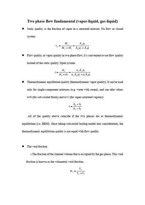
Two phase flow fundamental (vapor-liquid, gas-liquid) ● Static quality, is the fraction of vapor in a saturated mixture. No flow or closed system.gg g st g l g g l l M A x M M A A ρρρ==++● Flow quality, or vapor quality in two phase flow, it’s convenient to use flow quality instead of the static quality. Open system. g g g g g l g g g l l l m u A x m m u A u A ρρρ==++● Thermodynamic equilibrium quality (thermodynamic vapor quality). It can be used only for single-component mixtures (e.g. water with steam), and can take values x<0 (for sub-cooled fluids) and x>1 (for super-saturated vapours)m l g lh h x h h -=- All of the quality above coincide if the two phases are at thermodynamic equilibrium (i.e. HEM). Once taking subcooled boiling model into consideration, the thermodynamic equilibrium quality is not equal with flow quality.● The void fractioni. T he fraction of the channel volume that is occupied by the gas phase. This void fraction is known as the volumetric void fraction.gV g l V V V α=+ii. T he fraction of the channel cross-sectional area that is occupied by the gas phase. This void fraction is known as the cross-sectional void fraction. It is the widely utilized void fraction definition., gA g l A or A A αα=+iii. T he local void fraction refers to that at a one single point or very small volume. Therefore it takes the values of 1 or 0.● Phase velocity and superficial velocitySuperficial velocity is a hypothetical flow velocity calculated as if the given phase or fluid were the only one flowing or present in a given cross sectional area. The velocity of the given phase is calculated as if the second phase was ignored. In engineering of multiphase flows and flows in porous media, superficial velocity (j ) is commonly used, because it is the value which is unambiguous, while real velocity is often spatially dependent and subject to many assumptions.e,(1)(1)phas phase phase phase phase g g l ll g l gQ Q u j A Aj u j u j j j u u αααα====-=+=-+, ● Drift velocity of gas phase with respect to the volumetric center of the mixture: gj g V u j =-求孔隙率模型● Homogeneous equilibrium model (HEM)111()g sx x αρρ=-+ The velocity ratio is a concept utilized in separated flow types. Introducing the ideainto the HEM void fraction equation results in111()g sx S x αρρ=-+ Where Slip ratio, or velocity ratio is the ratio of the velocity of the vapor phase to the velocity of the liquid phase. (gl u S u =)With slip void fraction model, the cross-sectional void fraction and volumetric void fraction is derived:1(1)V S αααα=+-。

单相流与两相流的结合(pi-ipr)方法1.单相流与两相流的结合在油田开发中起到了重要作用。
The combination of single-phase flow and two-phase flow plays an important role in oil field development.2.通过pi-ipr方法可以更准确地预测地下油藏的产能。
The combination of pi-ipr method can more accurately predict the productivity of underground oil reservoirs.3.单相流指的是在介质内只有一种流体的流动状态。
Single-phase flow refers to the flow state of only one fluid in the medium.4.两相流包括气液两相流和液固两相流。
Two-phase flow includes gas-liquid two-phase flow and liquid-solid two-phase flow.5. pi-ipr方法能够同时考虑单相流和两相流的影响。
The pi-ipr method can simultaneously consider the influence of single-phase flow and two-phase flow.6.单相流和两相流的结合提高了油藏的开发效率。
The combination of single-phase flow and two-phase flow has improved the development efficiency of oil reservoirs.7.通过对单相流和两相流的综合分析,可以更好地理解地下储层的性质。
Through the comprehensive analysis of single-phase flow and two-phase flow, the properties of underground reservoirs can be better understood.8. pi-ipr方法可以帮助工程师更准确地设计油田开发方案。
Scientia Iranica B(2011)18(4),923–929Sharif University of TechnologyScientia IranicaTransactions B:Mechanical EngineeringExperimental investigation of air–water,two-phase flow regimes in vertical mini pipeP.Hanafizadeh,M.H.Saidi∗,A.Nouri Gheimasi,S.GhanbarzadehSchool of Mechanical Engineering,Sharif University of Technology,Tehran,P.O.Box11155-9567,IranReceived8November2010;revised28April2011;accepted12June2011KEYWORDSMini pipes;Two-phase flow; Flow pattern; Visualization; Flow pattern map.Abstract In this study,the flow patterns of air–water,two-phase flows have been investigated experimentally in a vertical mini pipe.The flow regimes were observed by a high speed video recorder in pipes with diameters of2,3and4mm and length27,31and25cm,respectively.The comprehensive visualization of air–water,two-phase flow in a vertical mini pipe has been performed to realize the physics of such a two-phase flow.Different flow patterns of air–water flow were observed simultaneously in the mini pipe at different values of air and water flow rates.Consequently,the flow pattern map was proposed for flow in the mini-pipe,in terms of superficial velocities of liquid and gas phases.The flow pattern maps are compared with those of other researchers in the existing literature,showing reasonable agreement.©2011Sharif University of Technology.Production and hosting by Elsevier B.V.All rights reserved.1.IntroductionGas–liquid,two-phase flow in micro structures has played an important role in several industrial and medical applications, such as micro heat exchangers,lab-on-chips,bio-MEMS and micro cooling electronics.Physical perception of micro flows is critical in order to optimize and develop the design of such devices.Two-phase flows at mini and micro scale have recently attracted the attention of scientists as a result of its wide usage in advanced science and technology,namely Micro-Electro-Mechanical Systems(MEMS),chemical engineering, bioengineering,medical devises,micro cooling systems,micro structures in computers,etc.The literature survey on this issue has been categorized into adiabatic and phase change work, which has been summarized in this paper.∗Corresponding author.E-mail address:saman@(M.H.Saidi).1.1.Adiabatic worksThe works of Suo and Griffith[1]were among the first studies concentrating on flow patterns in microchannels.They detected three different flow patterns,namely,bubbly/slug, slug and annular flow,in their studies,using channels with widths in the range of0.514–0.795mm.Sadatomi et al.[2] proposed flow regime maps in vertical rectangular channels and indicated that channel geometries have little influence in noncircular channels with large hydraulic diameters greater than10mm.Xu et al.[3]investigated concurrent vertical two-phase flow in a vertical rectangular channel with a narrow gap, experimentally.They reported that with a decrease in channel gap,the transition from one flow regime to another occurs at smaller gas flow rates.They developed a new criterion to predict transition from annular flow,as well.Hestroni et al.[4] performed experiments for air–water and steam–water flow in parallel triangular micro-channels,developed a practical modeling approach for two-phase micro-channel heat sinks and considered the discrepancy between flow patterns of air–water and steam–water flow in parallel micro-channels. Fukagata et al.[5]simulated an air–water two-phase flow in a20µm ID tube,numerically,with focus upon flow and heat transfer characteristics in the bubble train flows.He and Kasagi[6]simulated numerically adiabatic air water slug flow in a micro tube.They focused on pressure drop characteristics and their modeling.They found that the total pressure drop of a slug flow can be decomposed into a frictional pressure drop and a pressure drop over the bubble itself.Carlson et al.[7]1026-3098©2011Sharif University of Technology.Production and hosting by Elsevier B.V.All rights reserved.Peer review under responsibility of Sharif University of Technology.doi:10.1016/j.scient.2011.07.003924P.Hanafizadeh et al./Scientia Iranica,Transactions B:Mechanical Engineering18(2011)923–929investigated characteristics of multiphase dynamics,especially two-phase gas–liquid flow,by means of advanced numerical simulations.They compared two Computational Multi-Fluid Dynamic(CMFD)codes,Fluent and TransAT,and reported a prediction of recirculating flow in the bubbly flow case using TransAT,while significant recirculation was not observed in the solution using Fluent.Saison and Wongwises[8]performed a series of experiments in a horizontal circular micro channel with an inner diameter of0.15mm.They presented a flow pattern map in terms of the phase superficial velocities, and proposed a new pressure drop correlation for practical application.1.2.Phase change worksThe pool boiling heat transfer,in a vertical narrow annular with closed bottoms,was observed through a transparent quartz shroud by Yao and Chang[9],and stages of evolving boiling phenomena with an increase in heat flux were reported. Several researchers observed three basic flow patterns,namely, bubbly,slug and annular flow,in the mini pipe and channel. Damianides and Westwater[10]performed experiments with a1mm tube,and Mertz et al.[11]and Kasza et al.[12] studied the flow visualization of water nucleation in a single rectangular channel of2.5mm by6mm.Lin et al.[13]used a single round tube with2.1mm inside diameter for their experiments,and compared the flow transitions with those predicted by Bernea et al.[14].Sheng and Palm[15]performed their experiments with1–4mm diameter tubes.Cornwell and Kew[16]found three different flow patterns for R-113, namely,isolated bubbles confined bubbles and slug/annular flow,in rectangular channels with cross sectional areas of 1.2–0.9mm and3.5–1.1mm.Ory et al.[17]considered the effects of capillary,inertia,friction and gravity forces on the velocity distribution and temperature field along a single capillary two-phase flow in a heated micro-channel.Research dealing with gas–liquid,two-phase flow in micro-channels,in situations where fluid inertia was significant in comparison with surface tension,was reviewed by Ghiaasiaan and Abdel-Khalik[18].Jiang et al.[19]studied the boiling of water in triangular micro-channels,having widths of50and100µm. They observed individual bubbles at low heat fluxes,and an abrupt change in flow pattern to an unstable slug flow with increasing heat flux.Chedester and Ghiaasiaan[20]addressed the hydro-dynamically controlled Onset of a Significant Void (OSV)in heated micro tubes.They derived a simple semi-empirical correlation for the radius of departing bubbles at the OSV point to show the accuracy of their hypothesis.Some experimental studies have been reported on gas liquid two-phase flow in mini and micro conduits by Kandlikar[21],Lee and Mudawar[22]and Serizawa et al.[23].The three zone boiling heat transfer model was developed by Thome et al.[24]. Revellin and Thome[25]used an optical measurement method for two-phase characteristics of R-134a and R-245fa,in0.5mm and0.8mm diameter channels,to determine the frequency of bubbles existing in the microevaporator.They detected four flow patterns,namely,bubbly,slug,semi-annular and annular flow,whose transitions were not well compatible with neither the macroscale map of refrigerants nor the microscale map of air–water flow.Sobierska et al.[26] experimentally investigated the water boiling phenomena in a vertical rectangular microchannel,with a hydraulic diameter of0.48mm.They observed three main flow patterns,namely, bubbly,slug and annularflow.Figure1:Schematic of test apparatus.Due to the effects of surface tension,two-phase flows at mini and micro scale have different behavior in comparison with the macro scale.The aim of the present work is to visualize flow regimes in air–water two-phase flows and propose a flow regime map for such flows in vertical mini pipes.The neural network technique is implemented to recognize and predict a gas–liquid,two-phase flow pattern in mini tubes,having diameters of2,3and4mm.2.Experimental setupThis study is carried out by experimental apparatus schematically shown in Figure1.Air and water are used as gas and liquid phases in the experiments.The water flow rates are regulated by the needle valves and are measured by the cali-brated rotameter.Air and water are mixed together in a mixer made of acrylic glass and placed at the bottom of the riser pipe. The compressed air is fed by the compressor via an air injec-tor,which is schematically depicted in Figure2.The water flows from the center hole of a mixer,with a diameter of2mm,while air is injected into the holes around the center hole,each having 1mm diameter.The air flow rates are set by the regulator valve and are continuously measured by the calibrated gas rotameter. The overall height and inside diameter of the riser pipe are sum-marized in Table1.In order to have the opportunity to visually observe the two-phase flow patterns,the riser pipe was made of transparent glass.The air water mixture was directed upward through the riser,separated in the separation tank at the top of the riser and the air was discharged into the atmosphere.Differ-ent flow regime images were captured by a digital high speed camera,with a frame rate of1200fps,from the test section of the upriser.The test section is placed after the entrance section to diminish the effect of the entrance region.The length of the entrance section is about500mm.The superficial air and water velocities are0.5–10m/s and0.05–1m/s,respectively.P.Hanafizadeh et al./Scientia Iranica,Transactions B:Mechanical Engineering 18(2011)923–929925Figure 2:Schematic of air and watermixer.Figure 3:(a)RGB picture;(b)gray picture;and (c)subtracting and median process of flow in the pipe (3mm diameter).3.Experimental results 3.1.Image processingImage processing techniques must be performed in order to extract features from the images of the two-phase flow.Each picture has 8bit RGB (red,green and blue)color format,being converted from RGB to a grey scale mode.The output image has 256grey levels from 0(black)to 255(white).It is difficult to extract the bubbles directly from an original digital image and therefore preprocessing procedures must be undertaken to reduce noise and improve the quality of the images.An image-subtracted algorithm was used to reduce background noise by subtracting the background image from each dynamic image.In order to smooth the image border,a median filter was also used.A sliding window (3×3)was used in this process,and the median gray level of the pixels in the window was ter,the gray level of the pixels located at the center of the window was replaced by the median.The result of these processes is shown in Figure 3.3.1.1.Inverting binary imageThe images were converted from grayscale to binary mode by threshold segmentation,and an iterative procedure was used to calculate the optimizing threshold as follows [27]:Figure 4:Binary image of two-phase flow in the mini pipe.(a)The minimum and maximum of the gray level,namely Z land Z k ,are found in the image,and the initial value of the threshold is derived from their arithmetic average as:T 0=(Z k +Z l )/2.(1)(b)According to the initial value of threshold T K ,the imageis divided into two parts,namely,object and background,and the average value of the gray level in each part is calculated as:Z O =−Z (i ,j )<T kZ (i ,j )N O,(2)Z B =−Z (i ,j )>T kZ (i ,j )N B,(3)where Z (i ,j )is the gray level of the pixel (i ,j )in the image,N O is the number of the pixels in which Z (i ,j )is less than T K ,and N B is the number of pixels in which Z (i ,j )is more than T K .(c)The new threshold is calculated based on the arithmeticaverage of the object and background segments of the image as:T k +1=(Z O +Z B )/2.(4)If T K =T K +1,then the algorithm is finished,else K ≪=K +1,and turn to step (b).The binary image of the bubbles in the vertical pipe,which is the result of the above procedure,is shown in Figure 4.3.1.2.Image morphology processingSome morphological functions,such as dilation,erosion,opening and closing operations,were applied to modify the shapes of bubbles.Dilation adds pixels to the boundaries of the objects in an image,while erosion removes pixels on the object boundaries.The definition of a morphological opening of an image is erosion followed by dilation,using the same structuring element for both operations.The related operation,morphological closing of an image,is the reverse.It consists of dilation followed by erosion,with the same structuring element.Both of them do not significantly alter the area or shape of objects.The opening operation removes small objects and smoothes boundaries.Borders removed by erosion are restored by dilation,but small objects that were absorbed during erosion do not reappear after dilation.The closing operation was used to fill tiny holes and smooth boundaries.Objects were expanded by dilation and then reduced by erosion,so borders were smoothed and holes were filled [28,29].After926P.Hanafizadeh et al./Scientia Iranica,Transactions B:Mechanical Engineering 18(2011)923–929Figure 5:Final image of two-phase flow in the mini pipe.these operations,the result of image processing is shown in Figure 5.Bubble images of two-phase flow were clear using the above image processing,and it prepared bubbles for quantitative analysis,such as measuring area,perimeter and diameter.3.2.Flow pattern mapIn the experimental procedure while varying gas or liquid mass flow rate,a 10s film was recorded from the flow regime at a speed of 1200fps.The recorded film was replayed in slow motion for recognition of flow regimes.Each film converted to separate frames in a picture format using Adobe Premiere software.The achieved pictures were used as inputs of image processing techniques.The final binary pictures were used for the mentioned post processing procedure,such as flow regimedetection,void fraction and bubble velocity calculation,etc.Figure 6shows those typical flow regimes observed in the vertical,co-current,air–water,two-phase flows,in the 3mm mini pipe.Four basic flow patterns,namely,bubbly,slug,churn and annular,accompanied by their transitions,are illustrated in these figures.The visualization shows that air–water two-phase flows in mini pipes do not have three dimensional behaviors,especially in bubbly and slug flows.The final processed images of different flow regimes in air–water,two-phase flow in mini pipes have been presented in Figure 7.Figures 8–10show the flow pattern map for a vertical round tube with inner diameters of 2,3and 4mm,respectively.The proposed maps are in terms of superficial velocities of phases,and the four main flow patterns are depicted in these maps.In Figure 11,the achieved flow pattern for the pipe with 2mm ID was compared to the work of Ide et al.[30],shown by a solid line.They divided the flow pattern map into the four main regions,namely,dispersed bubbly flow,intermittent flow,churn flow and annular flow.The comparison shows that the bubbly and annular flows in the present work are not well in accordance with those of Ide et al.In the present work,the dispersed bubbles were not seen,because the air bubble injector did not have very thin holes.As a result,the created bubbles mostly have diameters in the range of the pipe diameter.Even the existence of air injectors with thin holes cannot guarantee the creation of bubbly flow.In the case of small bubbles occurring,as a result of thin holes in the air injector and the developed two-phase flow,they would collapse,resulting in large bubbles know as intermittent flow.Bubbly flows are mainly promoted by bubble breaking mechanisms,due to turbulence effects.It seems that in small diameter pipes,the formation of a specific flowpatterns(a)Bubbly.(b)Bubbly-slug.(c)Slug.(d)Messy-slug.(e)Churn.(f)Wispy-annular.(g)Ring.(h)Wavy-annular.(i)Annular.Figure 6:Different flow patterns in a vertical pipe with 2mm diameter.P.Hanafizadeh et al./Scientia Iranica,Transactions B:Mechanical Engineering18(2011)923–929927(a)Bubbly.(b)Slug.(c)Messy-slug.(d)Churn.(e)Ring.(f)Wavy-annular.Figure7:Final processed image of different two-phase flow regimes in the minipipe.Figure8:Flow patterns for2mm innerdiameter.Figure9:Flow patterns for3mm inner diameter.mainly depends on mixer configuration.The radial air supplierused in this study makes intermittent flow patterns,such asslug and churn flows,while the air supply in the tube centerfavors annular flow.This can be the reason for an absence ofannular flow in the proposed flow patterns.The comparison offlow patterns also reveals that the slug,messy slug andsemi-Figure10:Flow patterns for4mm inner diameter.annular flows in the proposed map are in accordance with theintermittent flow of Ide et al.[30].In the present study,a noticeable difference between flowpattern maps for vertical pipes with various diameters of2,3and4mm is not seen.This can be justified in regard tothe fact that the dominant forces acting on the air–watermixture in the small diameter pipes,namely,gravitation,inertia,surface tension and buoyancy forces,are in the sameorder of magnitude.This concept clearly indicates that thesethree flow patterns can be combined to form a new flow patternfor the gas–liquid,two-phase flow in small diameter pipes.A combination of these three flow patterns results in a newflow pattern map,which is illustrated in Figure12.A FuzzyC-Means clustering technique(FCM)was used to classify theflow patterns.The solid lines in the figure show the transitionregion of the flow patterns.This figure shows the achieved flowmap for mini pipes with diameters in the range of2–4mm.4.ConclusionIn this paper,air–water,two-phase flow patterns wereinvestigated experimentally for mini pipes with diameters of2,3and4mm.An image processing technique was used fordetection of flow patterns from pictures derived from filmsrecorded with a high speed camcorder.The obtained flowpatterns reveal that there is no noticeable difference between928P.Hanafizadeh et al./Scientia Iranica,Transactions B:Mechanical Engineering 18(2011)923–929Figure 11:Comparison between the achieved flow patterns with the work of Ide et al.[30]for a pipe with diameter of 2mm.Figure 12:Proposed two-phase vertical upward flow pattern map.two-phase,upward flow patterns in this range of diameters.A new flow pattern map was achieved for vertical mini pipes,due to a comparison of the flow patterns of these three diameters of pipe.The proposed map was compared with existing research.A comparison of the present work and previous research shows that the flow patterns of slug,messy slug and semi-annular in the present work are compatible with the intermittent flow pattern of Ide et al.[30].However,in the present study,the annular flow is seen at a lower superficial air velocity than that in the work of Ide et al.[30].AcknowledgmentsThis research was funded by Iran Supplying Petrochemical Industries,Parts,Equipment and Chemical Design Corporation (SPEC),as a joint research project with Sharif University of Technology (project No.KPR-8628077).References[1]Suo,M.and Griffith,P.‘‘Two-phase flow in capillary tubes’’,Int.J.Basic Eng.,86,pp.576–582(1964).[2]Sadatomi,Y.,Sato,Y.and Saruwatari,S.‘‘Two-phase flow in verticalnoncircular channels’’,Int.J.Multiphase Flow ,8,pp.641–655(1982).[3]Xu,J.L.,Cheng,P.and Zhao,T.S.‘‘Gas–liquid two-phase flow regimes inrectangular channels with mini/micro gaps’’,Int.J.Multiphase Flow ,25,pp.411–432(1999).[4]Hetsroni,G.,Mosyak, A.,Segal,Z.and Pogrebnyak, E.‘‘Two-phaseflow patterns in parallel micro-channels’’,Int.J.Multiphase Flow ,29,pp.341–360(2003).[5]Fugakata,K.,Kasagi,N.,Ua-arayaporn,P.and Himeno,T.‘‘Numericalsimulation of gas liquid two-phase flow and convective heat transfer in a micro tube’’,Int.J.Heat and Fluid Flow ,28,pp.72–82(2007).[6]He,Q.and Kasagi,N.‘‘Numerical investigation on flow pattern andpressure drop characteristics of slug flow in a micro tube’’,6th Int.ASME Conf.on Nanochannels,Microchannels and Minichannels ,Darmstadt,Germany,pp.24–35(2008).[7]Carlson,A.,Kudinov,P.and Narayanan,C.‘‘Prediction of two-phase flowin small tubes:a systematic comparison of state-of-the-art CMFD codes’’,5th Europe Thermal-Sci.Conf.,The Netherlands,pp.138–150(2008).[8]Saisorn,S.and Wongwises,S.‘‘An experimental investigation of two-phaseair–water flow through a horizontal circular micro-channel’’,Exp.Thermal Fluid Sci.,33,pp.306–315(2009).[9]Yao,S.C.and Chang,Y.‘‘Pool boiling heat transfer in a confined space’’,Int.J.Heat Mass Transf.,26,pp.841–848(1983).[10]Damianides,D.A.and Westwater,J.W.‘‘Two-phase flow patterns in acompact heat exchanger and in small tubes’’,2nd UK National Conf.on Heat Transf.,11,United Kingdom,London,pp.1257–1268(1988).[11]Mertz,R.,Wein,A.and Groll,C.‘‘Experimental investigation of flow boilingheat transfer in narrow channels’’,Calore e Technologia ,14(2),pp.47–54(1996).[12]Kasza,K.E.,Didascalou,T.and Wambsganss,M.W.‘‘Microscale flow visu-alization of nucleate boiling in small channels:mechanisms influencing heat transfer’’,Int.Conf.on Compact Heat Exchanges for the Process Indus-tries ,New York,USA,pp.343–352(1997).[13]Lin,S.,Kew,P.A.and Cornwell,K.‘‘Two-phase flow regimes and heattransfer in small tubes and channels’’,11th Int.Heat Transf.Conf.,Kyongju,Korea,2,pp.45–50(1998).[14]Barnea,D.,Luninsky,Y.and Taitel,Y.‘‘Flow pattern in horizontal andvertical two-phase flow in small diameter pipes’’,Canadian J.Chem.Eng.,61,pp.617–620(1983).[15]Sheng, C.H.and Palm, B.‘‘The visualization of boiling in small-diameter tubes’’,Int.Conf.on Heat Transport and Transport Phenomena in Microsystems ,Banff,Canada,pp.44–53(2001).[16]Cornwell,K.and Kew,P.A.‘‘Boiling in small parallel channels’’,CEC Conf.on Energy Eff.in Process Tech.,Athens,Greece,pp.624–638(1992).[17]Ory, E.,Yuan,H.,Prosperetti, A.,Popinet,S.and Zaleski,S.‘‘Growthand collapse of a vapor bubble in a narrow tube’’,Phys.Fluids ,12,pp.1268–1277(2000).[18]Ghiaasiaan,S.M.and Abdel-Khalik,S.I.‘‘Two-phase flow in micro-channels’’,Adv.Heat Transf.,34,pp.145–253(2001).[19]Jiang,L.,Wong,M.and Zohar,Y.‘‘Forced convection boiling in a micro-channel heat sink’’,Int.J.Micro-Electro-Mech.Sys.,10,pp.80–87(2000).[20]Chedester,R.C.and Ghiaasiaan,S.M.‘‘A proposed mechanism for hydrodynamically-controlled onset of significant void in microtubes’’,Int.J.Heat Fluid Flow ,23,pp.769–775(2002).[21]Kandlikar,S.G.‘‘Fundamental issues related to flow boiling in minichan-nels and microchannels’’,Exp.Therm.Fluid Sci.,26,pp.389–407(2002).[22]Lee,J.and Mudawar,I.‘‘Two phase flow in high heat flux micro channelheat sink for refrigeration cooling applications’’,Int.J.Heat Mass Transf.,48,pp.928–955(2005).[23]Serizawa,A.‘‘Gas liquid two-phase flow in microchannels’’,In MultiphaseFlow Handbook ,C.T.Crowe,Ed.,2nd ed.,pp.830–887,CRC Press (2006).[24]Thome,J.R.,Dupont,V.and Jacobi, A.M.‘‘Heat transfer model forevaporation in micro channels’’,Int.J.Heat Mass Transf.,47,pp.3375–3385(2004).P.Hanafizadeh et al./Scientia Iranica,Transactions B:Mechanical Engineering18(2011)923–929929[25]Revellin,R.and Thome,J.R.‘‘Experimental investigation of R-134a andR-245fa two-phase flow in microchannels for different flow conditions’’, Int.J.Heat Fluid Flow,28,pp.63–71(2007).[26]Sobierska, E.,Kulenovic,R.and Mertz,R.‘‘Heat transfer mechanismand flow pattern during flow boiling of water in a vertical narrow channel experimental results’’,Int.J.Thermal Sci.,46,pp.1172–1181 (2007).[27]Shi,L.‘‘Fuzzy recognition for gas–liquid two-phase flow pattern based onimage processing’’,Proc.of13rd IEEE Int.Conf.on Control and Automation, pp.1424–1427(2007).[28]Heijmans,H.J.A.M.,Morphological Image Operators,Academic Press,NewYork(1994).[29]/help/toolbox/images/index.html.[30]Ide,H.,Kariyasaki,A.and Fukano,T.‘‘Fundamental data on the gas–liquidtwo-phase flow in minichannels’’,Int.J.Thermal Sci.,46,pp.519–530 (2007).Pedram Hanafizadeh received his M.S.and Ph.D.Degrees in Mechanical Engineering from the Centre of Excellence in Energy Conversion at Sharif University of Technology,Tehran,Iran,in2005and2010,respectively.His work is mainly concentrated on the field of Multiphase Flow,Experimentally, Numerically and Analytically.His research interests include Characteristics of Multiphase Flow,Heat Transfer,Boiling and Condensation,Instrumentation in Fluid Flow,Image Processing for Flow Field Analysis,and Industrial and Applicable Usage of Multiphase Flow.Mohammad Hassan Saidi is Professor and Chairman of the School of Mechanical Engineering at Sharif University of Technology,Tehran,Iran. His current research interests include Multiphase Flows,Heat Transfer Enhancement in Boiling and Condensation,Modelling of Pulse Refrigeration, Vortex Tube Refrigerator,Indoor Air Quality and Clean Room Technology, Energy Efficiency in Home Appliances and Desiccant Cooling Systems.Arash Nouri Gheimasi obtained his B.S.Degree in Mechanical Engineering in2010,and is currently an M.S.student at the Centre of Excellence in Energy Conversion at the School of Mechanical Engineering,Sharif University of Technology,Tehran,Iran,under the supervision of Professor Saidi.His B.S. thesis involved work on the Characteristics of Gas-Liquid Two-Phase Flow in Mini Pipes and he is now working on Application of Visual Techniques in Two-Phase Flow.His research interests include the area of Two Phase Flow and Its Industrial Applications.Soheil Ghanbarzade received his B.S.and M.S.Degrees in Mechanical Engineering from the Centre of Excellence in Energy Conversion at Sharif University of Technology in2008and2010,respectively.Since then he has worked under the supervision of Professor M.H.Saidi as research staff in the Multiphase Group.His research interests include:Analytical,Numerical and Experimental Methods to Study Characteristics of Large Scale and Mini Scale Air-Water,Two-Phase Flows.He holds a Gold medal from the13th National Olympiad of Mechanical Engineering in Iran,and is currently a Ph.D.student of Petroleum Engineering at the University of Texas,Austin,USA.。