第七章 无线红外通信
- 格式:docx
- 大小:270.84 KB
- 文档页数:5

红外通信的基本原理红外通信作为一种无线通信技术,在现代社会的各个领域都有着广泛的应用。
其基本原理是利用红外线作为信息的传输媒介,通过发送端将信息编码成红外光信号,再由接收端解码还原成原始信息。
红外通信技术具有传输速度快、安全性高、干扰少等优点,因此在遥控器、红外对讲、红外测温等领域得到了广泛应用。
红外通信的基本原理是利用红外线这一特定波长的电磁波来传输信息。
红外线波长范围在可见光和微波之间,具有较强的穿透性,因此适合用于近距离通信。
红外线在光学、电子等领域有着重要的应用价值。
红外通信系统通常由发送端和接收端两部分组成。
发送端通过红外发射器将信息信号转换成红外光信号,发送到接收端。
接收端的红外接收器接收到红外光信号后,将其转换成电信号,经过解码处理后还原成原始信息。
整个过程实现了信息的传输和接收。
红外通信的基本原理是通过调制解调技术来实现信息的传输。
发送端通过调制器将要传输的信息信号转换成一定频率的红外光信号,再由解调器在接收端将接收到的红外光信号转换成原始信息信号。
这样就实现了信息的传输和接收。
在红外通信系统中,编码和解码是至关重要的环节。
发送端将信息信号通过编码器转换成特定的编码格式,再送入调制器进行调制。
接收端收到红外光信号后,首先经过解调器解调,再由解码器将编码格式转换成原始信息信号。
编码和解码的准确性直接影响到信息的传输质量。
红外通信技术在现代社会的各个领域都有着广泛的应用。
在家庭生活中,遥控器、红外对讲等设备都是基于红外通信技术工作的。
在工业领域,红外测温仪、红外监控系统等设备也是利用红外通信技术实现信息传输。
此外,在医疗、军事、航空航天等领域,红外通信技术也发挥着重要作用。
总的来说,红外通信的基本原理是利用红外线作为信息的传输媒介,通过编码、调制、解调、解码等技术实现信息的传输和接收。
红外通信技术具有传输速度快、安全性高、干扰少等优点,在现代社会得到了广泛的应用。
随着科技的不断进步,红外通信技术将会有更广阔的发展空间,为人类的生活带来更多便利和安全。


红外通讯的原理和应用1. 红外通讯的原理红外通讯是一种无线通信技术,通过红外线传输信息。
它基于红外线的物理特性,利用红外线的辐射和接收来实现通信。
红外通讯的原理主要包括以下几个方面:1.1 红外线的发射和接收红外线是一种电磁波,波长范围在0.75µm至1000µm之间,位于可见光和微波之间。
在红外通讯系统中,红外线由红外发射器(如红外二极管)发射出去,并由红外接收器(如红外光电二极管)接收。
红外线的发射和接收是实现红外通讯的基础。
1.2 编码和解码为了在红外通讯中传输信息,需要将信息进行编码和解码。
常见的编码方式包括脉冲宽度调制(PWM)和脉冲位置调制(PPM)。
编码器将要传输的信息转换成相应的脉冲信号,发送给红外发射器。
解码器接收红外线信号,并将其转换回原始信息。
1.3 障碍物的影响红外线在传输过程中会受到障碍物的影响。
障碍物(如墙壁、玻璃等)会吸收或散射红外线,导致信号弱化或失真。
因此,在设计红外通讯系统时,需要考虑障碍物对信号传输的影响。
1.4 波长选择红外通讯中波长的选择也很重要。
不同波长的红外线在传输距离、穿透性和抗干扰能力方面有所差异。
常见的红外通讯波长包括近红外和远红外。
2. 红外通讯的应用红外通讯具有许多应用领域,以下是其中几个常见的应用:2.1 遥控器红外遥控器是红外通讯最常见的应用之一。
遥控器通过发射红外线信号来控制电视、音响、空调等设备。
遥控器工作原理是将遥控信号编码成红外脉冲信号,并传输给相应设备的红外接收器,从而实现控制。
2.2 红外传感器红外传感器是利用红外线的物理特性来检测物体或环境的传感器。
常见的红外传感器有人体感应器、温度传感器等。
人体感应器通过接收红外线反射信号来检测人体的存在,广泛应用于安防系统和智能家居等领域。
2.3 红外通信红外通信在短距离通信中有广泛应用。
例如,红外数据传输使用红外通讯原理来实现设备之间的数据传输,如红外打印机、红外测距仪等。

第五章总结与期望摘要红外无线通信,通常又叫红外光通信,是利用红外线传送信息的一种通信方式。
红外线通信所传输的内容是多样的,可以是音频信号,也可以是视频信号。
利用红外线,可以构成无绳电话及无线耳机系统。
红外线的传输距离不远,一般在十米以内,但可以避免频谱占用,信号失真等电气指标较易处理,应用于普通的办公室和家庭等场合应该已经可以满足要求。
红外线的应用范围很广,电视机、空调、微波炉等凡涉及到遥控的家电,一般均采用红外线来作为信号传输的载体。
本次设计的红外无线通信系统主要是传递音频信号。
该系统是由发射模块和接收模块组成。
发射模块的输入与音响设备相连接,从音响设备输出的音频信号调制红外光以后,由红外光发射机将调制的红外光向空间发射。
红外无线系统的接收部分将接收到的已调制红外光进行解调,还原出音频信号,然后送到扬声器发出声音。
本次设计的电路系统具有实用、成本低廉、使用方便的优点。
关键词红外线、发射、接收、调制、解调目录中文摘要 (Ⅰ)英文摘要 (Ⅱ)0 引言1 红外发射系统1.1 红外发射系统组成框图1.2 红外发射系统的工作原理分析1.2.1 直流稳压电源..............................................1.2.2 音频放大电路..............................................1.2.3 高频振荡电路..............................................1.2.4 高频放大电路..............................................1.2.5 频率调制电路..............................................1.2.6 高频功放电路..............................................1.2.7 红外发射电路..............................................2 红外接收系统2.1 红外接收系统的组成框图2.2 红外接收系统的工作原理分析2.2.1 直流稳压电源.................................................2.2.2 红外接收电路.................................................2.2.3 高频放大电路.................................................2.2.4 频率解调电路.................................................2.2.5 音频功放电路.................................................2.2.6 扬声器.......................................................3 红外通信系统的仿真3.1 仿真软件的介绍3.2 仿真调试4.安装、焊接、调试及性能分析5.结论6.致谢7.参考文献0 引言随着计算机与通信技术的飞速发展,计算机通信得到广泛应用,硬件技术可谓是日新月异,其总体趋势向着高集成度、高稳定性、高速和高性价比方向发展。
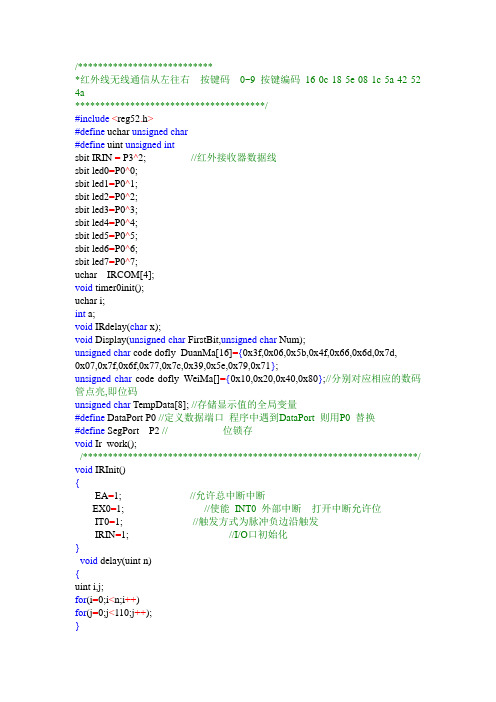
/****************************红外线无线通信从左往右按键码0~9 按键编码16 0c 18 5e 08 1c 5a 42 52 4a**************************************/#include<reg52.h>#define uchar unsigned char#define uint unsigned intsbit IRIN = P3^2; //红外接收器数据线sbit led0=P0^0;sbit led1=P0^1;sbit led2=P0^2;sbit led3=P0^3;sbit led4=P0^4;sbit led5=P0^5;sbit led6=P0^6;sbit led7=P0^7;uchar IRCOM[4];void timer0init();uchar i;int a;void IRdelay(char x);void Display(unsigned char FirstBit,unsigned char Num);unsigned char code dofly_DuanMa[16]={0x3f,0x06,0x5b,0x4f,0x66,0x6d,0x7d,0x07,0x7f,0x6f,0x77,0x7c,0x39,0x5e,0x79,0x71};unsigned char code dofly_WeiMa[]={0x10,0x20,0x40,0x80};//分别对应相应的数码管点亮,即位码unsigned char TempData[8]; //存储显示值的全局变量#define DataPort P0 //定义数据端口程序中遇到DataPort 则用P0 替换#define SegPort P2 // 位锁存void Ir_work();/*******************************************************************/ void IRInit(){EA=1; //允许总中断中断EX0=1; //使能INT0 外部中断打开中断允许位IT0=1; //触发方式为脉冲负边沿触发IRIN=1; //I/O口初始化}void delay(uint n){uint i,j;for(i=0;i<n;i++)for(j=0;j<110;j++);}/**********************************************************/void timer0init(void)//定时器0初始化{TMOD=0x02;TH0=0;TL0=0;EA=1;ET0=1;TR0=1;}void main(){timer0init();IRInit();while(1){}}void IR_IN(void) interrupt 0 //外部中断0{unsigned char j,k,N=0;EX0 = 0; //关闭T0IRdelay(15);if (IRIN==1){ EX0 =1;return;}//确认IR信号出现while (!IRIN); //等IR变为高电平,跳过9ms的前导低电平信号。

红外通信电路工作原理
红外通信是一种利用红外线传输信息的无线通信技术。
其基本原理是利用红外线载波进行信息的发送和接收。
红外通信电路主要由发射器和接收器组成。
发射器中包含一个发光二极管(LED),当通电时,LED会发出红外线信号。
接收器中包含一个光敏二极管(光电二极管),它能够感受到接收到的红外线信号。
当发射器中的LED发出红外线信号时,经过空气传播到接收器位置。
接收器中的光敏二极管会感受到这一红外线信号,并将其转化为电信号。
接收到的电信号经过放大和解调后,可以得到原始的信息信号。
红外通信电路的工作原理可以分为发送和接收的两个过程。
在发送过程中,发射器中的LED通过电流驱动,发出红外线信号。
在接收过程中,接收器接收到发射器发出的红外线信号,并将其转化为电信号。
整个通信过程实际上是通过红外线的发射和接收来实现信息的传输。
红外通信电路的优点包括无线传输、抗干扰能力强、成本低廉等。
然而,也存在一些缺点,比如传输距离相对较短、受到环境干扰较大等。
红外通信电路在日常生活中有广泛的应用,如遥控器、红外线测温仪、红外线遥感器等。
它不仅可以用于远程控制设备,还可以用于数据传输、通信连接等领域。
原文:Wireless Infrared CommunicationsI. IntroductionWireless infrared communications refers to theuse of free-space propagation of light waves in thenear infrared band as a transmission medium forcommunication(1-3), as shown in Figure 1. The communication can be between one portable communication device and another or between a portable device and a tethered device, called an access pointor base station. Typical portable devices includelaptop computers, personal digital assistants, andportable telephones, while the base stations are usually connected to a computer with other networkedconnections. Although infrared light is usually usedother regions of the optical spectrum can be used (sothe term wireless optical communications" insteadof wireless infrared communications" is sometimesused).Wireless infrared communication systems can becharacterized by the application for which they aredesigned or by the link type, as described below.A.ApplicationsThe primary commercial applications are as follows:²short-term cable-less connectivity for informationexchange (business cards, schedules, file sharing) between two users. The primary example is IrDA systems (see Section 4).²wireless local area networks (WLANs) provide network connectivity inside buildings. This can eitherbe an extension of existing LANs to facilitate mobility, or to establish “ad hoc”networks where there isno LAN. The primary example is the IEEE 802.11standard (see Section 4).²building-to-building connections for high-speednetwork access or metropolitan- or campus-area net-works.²wireless input and control devices, such as wirelessmice, remote controls, wireless game controllers, andremote electronic keys.B. Link TypeAnother important way to characterize a wirelessinfrared communication system is by the “link type”which means the typical or required arrangement ofreceiver and transmitter. Figure 2 depicts the twomost common configurations: the point-to-point system and the diffuse system.The simplest link type is the point-to-pointsystem. There, the transmitter and receiver must bepointed at each other to establish a link. The line-of-sight (LOS) path from the transmitter to the receivermust be clear of obstructions, and most of the transmitted light is directed toward the receiver. Hence,point-to-point systems are also called directed LOS systems. The links can be temporarily created for adata exchangesession between two users, or established more permanently by aiming a mobile unit ata base station unit in the LAN replacement application.In diffuse systems, the link is always maintainedbetween any transmitter and any receiver in the samevicinity by reflecting or |“bouncing”the transmittedinformation-bearing light off reflecting surfaces suchas ceilings, walls, and furniture. Here, the transmitter and receiver are non-directed; the transmitteremploys a wide transmit beam and the receiver hasa wide field-of-view. Also, the LOS path is not required. Hence, diffuse systems are also called non-directed non-LOS systems. These systems are wellsuited to the wirelessLAN application, freeing theuser from knowing and aligning with the locations ofthe other communicating devices.C. Fundamentals and OutlineMost wireless infrared communications systemscan be modeled as having an output signal Y (t) andan input signal X(t) which are related bywhere denotes convolution, C(t) is the impulse response of the channel and N(t) is additive noise.This article is organized around answering key questions concerning the system as represented by thismodel.In Section 2, we consider questions of optical design. What range of wireless infrared communications systems does this model apply to? How does C(t) depend on the electrical and optical properties ofthe receiver and transmitter? How does C(t) dependon the location, size, and orientation of the receiverand transmitter? How do X(t) and Y (t) relate to optical processes? What wavelength is used for X(t)?What devices produce X(t) and Y (t)? What is thesource of N(t)? Are there any safety considerations?In Section 3, we consider questions of communications design. How should a data symbol sequence bemodulated onto the input signal X(t)? What detection mechanism is best for extracting the informationabout the data from the received signal Y (t)? Howcan one measure and improve the performance of thesystem? In Section 4, we consider the design choicesmade by existing standards such as IrDA and 802.11.Finally, in Section 5, we consider how these systemscan be improved in the future.II. Optical DesignA. Modulation and demodulationWhat characteristic of the transmitted wave willbe modulated to carry information from the transmitter to the receiver? Most communication systemsare based on phase, amplitude, or frequency modulation, or some combination of these techniques.However, it is difficult to detect such a signal following nondirected propagation, and more expensivenarrow-linewidth sources are required(2). An effective solution is to use intensity modulation, wherethe transmitted signal's intensity or power is proportional to the modulating signal.At the demodulator (usually referred to as a detector in optical systems) the modulation can be extracted by mixing the received signalwith a carrierlight wave. This coherent detection technique is bestwhen the signal phase can be maintained. However,this can be difficult to implement and additionally, innondirected propagation, it is difficult to achieve therequired mixing efficiency. Instead, one can use directdetection using a photodetector. The photodetectorcurrent is proportional to the received optical signalintensity, which for intensity modulation, is also theoriginal modulating signal. Hence, most systems useintensity modulation with direct detection (IM/DD)to achieve optical modulation and demodulation.In a free-space optical communication system, thedetector is illuminated by sources of light energyother than the source. These can include ambientlighting sources, such as natural sunlight, fluorescent lamp light, and incandescent lamp light. Thesesources cause variation in the received photocurrentthat is unrelated to the transmitted signal, resultingin an additive noise component at the receiver.We can write the photocurrent at the receiver aswhere R is the responsivity of the receiving photodiode (A/W). Note that the electrical impulse responsec(t) is simply R times the optical impulse responseh(t). Depending on the situation, some authors use(t) and some use h(t) as the impulse response.B. Receivers and TransmittersA transmitter or source converts an electrical signal to an optical signal. The two most appropriatetypes of device are the light-emitting diode (LED)and semiconductor laser diode (LD).LEDs havea naturally wide transmission pattern, and so aresuited to nondirected links. Eye safety is much simpler to achieve for an LED than for a laser diode,which usually have very narrow transmit beams.The principal advantages of laser diodes are theirhigh energy-conversion efficiency, their high modulation bandwidth, and their relatively narrow spectral width. Although laser diodes offer several advantages over LEDs that could be exploited, mostshort-range commercial systems currently use LEDs.A receiver or detector converts optical power intoelectrical current by detecting the photon flux incident on the detector surface. Silicon p-i-n photodiodes are ideal for wireless infrared communications asthey have good quantum efficiency in this band andare inexpensive(4). Avalanche photodiodes are notused here since the dominant noise source is back-ground light-induced shot noise rather than thermalcircuit noise.C. Transmission W avelength and NoiseThe most important factor to consider whenchoosing a transmission wavelength is the availability of effective, low-cost sources and detectors. Theavailability of LEDs and silicon photodiodes operating in the 800 nm to 1000 nm range is the primaryreason for the use of this band. Another importantconsideration is the spectral distribution of the dominant noise source: background lighting.The noise N(t) can be broken into four components: photon noise or shot noise, gainnoise, receiver circuit or thermal noise, and periodic noise.Gain noise is only present in avalanche-type devices,so we will not consider it here.Photon noise is the result of the discreteness ofphoton arrivals. It is due to background lightsources, such as sun light, fluorescent lamplight,and incandescent lamp light, as well as the signaldependent source X(t) - c(t). Since the backgroundlight striking the photodetector is normally muchstronger than the signal light, we can neglect the dependency of N(t) on X(t) and consider the photonnoise to be additive white Gaussian noise with two-sided power spectral density where qis the electron charge, R is the responsivity, and Pnis the optical power of the noise (background light).Receiver noise is due to thermal effects in the receiver circuitry, and is particularly dependent on thetype of preamplifier used. With careful circuit design, it can be made insignificant relative tothe photon noise(5).Periodic noise is the result of the variation of fluorescent lighting due to the method of driving thelamp using the ballast. This generates an extraneous periodic signal with a fundamental frequency of44 kHz with significant harmonics to several MHz.Mitigating the effect of periodic noise can be doneusing high-pass filtering in combination with baselinerestoration(6), or by careful selection of the modulation type, as discussed in Section 3.1.D. SafetyThere are two safety concerns when dealing withinfrared co mmunication systems. Eye safety is a concern because of a combination of two effects: thecornea is transparent from the near violet to the nearIR. Hence, the retina is sensitive to damage from light sources transmitting in these bands. However,the near IR is outside the visible range of light, andso the eye does not protect itself from damage byclosing the iris or closing the eyelid. Eye safety canbe ensured by restricting the transmit beam strengthaccording to IEC or ANSI standards(7,8).Skin safety is also a possible concern. Possibleshortterm effects such as heating of the skin are accounted for by eye safety regulations (since the eyerequires lower power levels than the skin). Longtermexposure to IR light is not a concern, as the ambientlight sources are constantly submitting our bodies tomuch higher radiation levels than these communication systems do.III. Communications DesignEqually important for achieving the design goals ofwireless infrared systems are communications issues.In particular, the modulation signal format togetherwith appropriate error control coding is critical toachieving power efficiency. Channel characterizationis also important for understanding performance limits.A. Modulation TechniquesTo understand modulation in IM/DD systems, wemust look again at the channelmodeland consider its particular characteristics. First,since we are using intensity modulation, the channel input X(t) is optical intensity and we have theconstraint X(t). The average transmitted optical power PT is the time average of X(t). Our goalis to minimize the transmitted power required to attain a certain probability of bit error Pe, also knownas a bit error rate (BER).It is useful to define the signal-to-noise ratio SNRaswhere H(0) is the d.c. gain of the channel, i.e. itis the Fourier transform of h(t) evaluated at zerofrequency, soThe transmitted signal can be represented asThe sequence represents the digital informationbeing transmitted, whereis one of L possible datasymbols from 0 to L-1. The function Si(t) representsone of L pulse shapes with duration Ts, the symboltime. The data rate (or bit rate) Rb, bit time T,symbol rate Rs, and symbol time Ts are related asfollows:.There are three commonly used types of modulation schemes: on-off keying (OOK) with non-return-to-zero pulses, OOK with return-to-zero pulses ofnormalized width and pulse position modulation with L pulses (L-PPM). OOK and aresimpler to implement at both the transmitter and receiver than L-PPM. The pulse shapes for these modulation techniques are shown in Figure 3. Representative examples of the resulting transmitted signalX(t) for a short data sequence areshown in Figure4.We compare modulation schemes in Table 1 bylooking at measures of power efficiency and bandwidth efficiency. Bandwidth efficiency is measuredby dividing the zero-crossing bandwidth by the datarate. Bandwidth efficient schemes have severaladvantages—the receiver and transmitter electronicsare cheaper, and the modulation scheme is less likelyto be affected by multipath distortion. Power efficiency is measured by comparing the required transmit power to achieve a target probability of error Pefor different modulation techniques. Both andPPM are more power efficient than OOK, but at thecost of reduced bandwidth efficiency. However, for agiven bandwidth efficiency, PPM is more power efficient than,and so PPM is most commonlyused. OOK is most useful at very high data rates,say 100 Mb/s or greater. Then, the effect of multipath distortion is the most significant effect andbandwidth efficiency becomes of paramount importance(9).B. Error Control CodingError control coding is an important technique forimproving the quality of any digital communicationsystem. We concentrate here on forward error correction channel coding, as this specifically relates to wireless infrared communications; source coding andARQ coding are not considered here.Trellis-coded PPM has been found to be an effective scheme for multipath infrared channels(10,11).The key technique is to recognize that although ona distortion-free channel, all symbols are orthogonal and equidistant in signal space, this is not trueon a distorting channel. Hence, trellis-coding usingset partitioning designed to separate the pulse positions of neighboring symbols is an effective codingmethod. Coding gains of 5.0 dB electrical have beenreported for rate 2/3-coded 8-PPM over uncoded 16-PPM, which has the same bandwidth(11).C. Channel impulse response characterizationImpulse response characterization refers to theproblem of understanding how the impulse response C(t) in Equation (1) depends on the location, size,and orientation of the receiver and transmitter.There are basically three classes of techniques foraccomplishing this: measurement, simulation, andmodeling. Channel measurements have been described in several studies(9,12,2), and these formthe fundamental basis for understanding the channel properties. A particular study might generate a collection of hundreds or thousands of example impulse responses Ci(t) for configuration i. The collection of measured impulse responses Ci(t) can thenbe studied by looking at scatter plots of path lossversus distance, scatter plots of delay spread versusdistance, the effect of transmitter and receiver orientations, robustness to shadowing, and so on.Simulation methods have been used to allow directcalculation of a particular impulse response based ona site-specific characterization of the propagation environment(13,14). The transmitter, receiver, and thereflecting surfaces are described and used to generatean impulse response. The basic assumption is thatmost interior surfaces reflect light diffusely in a Lambertian pattern, i.e. all incident light, regardless ofincident angle, is reflected in all directions with anintensity proportional to the cosine of the angle ofthe reflection with the surface normal. The difficultywith existing methods is that accurate modeling requires extensive computation.A third technique attempts to extract knowledge gained from experimental and simulation-basedchannel estimations into a simple-to-use model. In (15), for example, a model using two parameters (onefor path loss, one for delay spread) is used to providea general characterization of all diffuse IR channels.Methods for relating the parameters of the modelto particular room characteristics are given, so thatsystem designers can quickly estimate the channelcharacteristics in a wide range of situations.翻译:无线红外通信I.导言无线红外通信指的是使用近红外波段的光作为通信传输介质的一种通讯方式(1-3),如图1所示。
第七章无线红外通信1800 年,英国科学家赫胥尔研究太阳光时,将一支温度计通过各种颜色的光,并用另一支不通过光谱的温度计作参照对比。
他发现当温度计从光谱的紫色末端向红色末端移动时,温度计的读数逐步升高,一直到红色末端之外的区域温度计的读数达到最高。
经反复验证,这个温度最高的区域在光带边缘处红光的外边,因这种射线存在的区域在可见光区末端以外而被称为红外线。
⏹红外线是一种人的肉眼看不见的光波,它是因为物质内部的分子、原子运动所产生的电磁辐射,是电磁波,其波段在可见光与微波波段之间( 0.761μm ~1 000μm) 。
⏹红外无线通信采用红外线作为无线传输载体,红外线作为载体可用于室内外以实现点对点的无线通信。
优点⏹①红外线可以代替传统设备之间的连接线缆作为通信载体,可大大降低线缆费用和设备维护费用,简单方便,成本低廉。
⏹②红外线的带宽比较宽,且不受无线管制,用它作通信载体能提供比较高的数据速率。
红外的数据传输速度可以高达16Mbit / s,所以红外线特别适合传输容量比较大的数据文件和多媒体信息流。
⏹③红外线遇不透明物体不能穿越,不容易被侦听,保密性好,并且红外线发射角度一般不超过30°,视线之外的设备很难对它构成干扰,安全性高。
⏹④红外线不受空间高频电磁波的干扰,在使用红外线传送信息时,干扰小。
⏹⑤红外线功耗低,最大功耗为几mA。
缺点⏹①由于红外线遇不透明物体不能穿越,所以必须在短距离范围内传输,通常传输距离是0.2m ~1m,发送接收方传输时中间不能有任何阻挡物,并且双方必须靠近,在允许的范围之内;⏹②由于红外线发射角度一般不超过30°,较小,所以可控性比较小,发送接收方的位置要求相对固定,移动性差;⏹③红外线只能实现点对点传输,不能实现点对多传输,只能在2 台设备之间连接;⏹④红外线只支持数据,模拟信号必须先转换成数字信号才能进行传输。
总之,红外无线通信技术是短距离无线传输技术的鼻祖,红外无线通信以低廉的成本和广泛的兼容性在无线通信领域占有重要地位。
采用红外无线传输可以不受空间电磁波的干扰,保密性好,安全性高,不需要埋电缆,电路合理,使用方便,经济实用,且在功能上易于扩展。
应用⏹在家庭生活中的应用-红外遥控⏹数字电视、机顶盒、家庭影院等⏹特点是不影响周边环境、不干扰其他电器设备。
由于红外线不能穿透墙壁,所以不同房间的家电可使用通用的遥控器且不会产生干扰; 电路简单,只要按电路连接正确,一般就可投入使用; 编解码容易,可进行多路遥控。
⏹现在红外遥控在家用电器、少儿玩具及短距离遥控中应用广泛。
在军事上的应用⏹基于红外线不受电磁波干扰,安全性高且不易受天气影响等优点在军事上受到广泛的运用。
⏹红外制导系统:是利用红外自动跟踪测量的方法,控制和引导导弹射向目标的技术。
这种技术利用红外探测器捕捉和跟踪目标所辐射的红外能量,经光电转换和信号处理后,给出目标相对于导弹的角度、角速度等信息,控制导弹按一定规律接近并命中目标。
⏹红外线在军事侦察方面也起到了举足轻重的作用。
在卫星上安装红外侦查系统可利用其上的红外望远镜及时发现大气层中射来的飞弹,并监视其飞行,也可利用卫星上的高分辨率的红外成像设备,昼夜侦察和监视对方的活动。
在医学方面的应用⏹按照物理知识,自然界中一切温度高于绝对温度( -273℃) 的物体都不断向外辐射红外线,这种现象称为热辐射。
⏹人体也有自身的红外线辐射特性,当人生病时,人体的热平衡受到破坏,红外辐射会发生变化,因此人的体温度变化是医学上诊断疾病的一项重要依据。
⏹采用红外热像仪记录人体的温度变化,将病变时的人体热像和正常生理状态下的人体热像进行比较,便可从热像是否有异常变化来判断病理状态。
在遥感探测方面的应用⏹红外在遥感探测方面的应用主要是利用红外光获取目标。
由于物体都能辐射和反射电磁波,并且物体的辐射和反射特性都不同,利用光学遥感器,远距离探测物体的所反射和辐射的红外特性的差异,经光学、电子技术处理后,就可确定目标的位置。
IrDA⏹Infrared Data Association⏹Founded in 1993 by around 50 companies⏹For last one meter⏹notebooks, digital cameras, desktops, printers, public phones, PDAs, palm PCs,electronic books, electronic wallets, cellular phones, pagers, watches, toys, and other mobile devices.⏹physically secure data transfer, Line-of-Sight (LOS) and very low bit error rate (BER)⏹SIR: 9.6-115.2 kbit/s, asynchronous, RZI, UART-like, 3/16 pulse⏹MIR: 0.576-1.152 Mbit/s, RZI, 1/4 pulse, HDLC bit stuffing⏹FIR: 4 Mbit/s, 4PPM⏹VFIR: 16 Mbit/s, NRZ, HHH(1,13)⏹UFIR: 96 Mbit/s, NRZI, 8B10B⏹GigaIR: 512 Mbit/s – 1Gbit/s, NRZI, 2-ASK, 4-ASK, 8B10B⏹5/10GigaIR: seems to be a new IrPHY coming soon⏹Range: standard: 1 m; low power to low power: 0.2 m; standard to low power: 0.3 m,The 10 GigaIR also define new usage models that supports higher link distances up to several meters.⏹Angle: minimum cone ±15°⏹Speed: 2.4 kbit/s to 1 Gbit/s⏹Modulation: baseband, no carrier⏹Infrared window⏹Wavelength: 850-900 nm⏹协议栈是指在通信协议管理时,将其自上而下分为各司其职的数个协议层,并把这些协议层层叠起来使之紧密联系从而形成了协议栈。
⏹IrDA 是一套针对点对点红外通信的层叠协议,每一层建立在本身下一层的上方,确保了建立与保持无差错的数据传递,其中无差错表示误码率为10-9。
⏹分为核心协议和可选协议IrDA协议⏹物理层IrPHY (The Physical Layer)作用:制定红外通信硬件的具体要求,包括红外光的特性、数据编码、不同波特率下的数据帧的结构。
❿链路建立协议层IrLAP (Link Access Protocol)作用:参数协商好后提供可靠无故障的数据交换❿链路管理协议层IrLMP (Link Management P~)作用:能够多路复用和数据链路的管理信息获取服务(IAS):为设备提供服务检索表微型传输协议(TTP):各个通道加入流控制保证数据传输的顺畅。
红外对象交换协议(IrOBEX):对文件及其他数据对象进行交换服务。
红外通信(IrCOMM):对串并口进行仿真,使得应用的串并口通信直接在IrDA平台上实现而无需转换。
红外局域网(IrLAN):为PC 或者其他设备提供IR 局域网通道。
IrDA 物理层定义了串行、半双工、距离0~100cm、点到点的红外通信规程,包括调制、视角(接收器和发射器之间红外传输方向上的角度偏差) 、视力安全、电源功率、传输速率、以及抗干扰性等,以保证各种品牌、种类的设备之间物理上的互连。
也保证在某些典型环境下(如存在环境照明——太阳光或灯光、及其它红外干扰) 的可靠通信,并将参加通信的设备之间的干扰降到最低。
⏹v1.0:数据传输率最高到115. 2 kbps⏹v1.1:数据传输率提高到4 Mbps,并兼容v1.0⏹v1.2:定义了最高速度为115. 2kbps下的低功耗选择⏹v1.3:低功耗选择推广到1.152Mbps和4Mbps⏹发送速度分类有三种:SIR、MIR 和FIR。
串行红外传输速度最大可达到115.2kb/s;MIR 则支持0.576Mb/s 和1.152Mb/s 的传输速度;FIR则通常用于4Mb/s 的速度⏹v1. 3 支持两种电源: 标准电源和低功率电源。
标准电源无差错传输距离为0~100cm, 最大视角至少15°;低功率电源选择应用于便携式设备和电信产业中, 无差错传输距离0~20 cm, 最大视角至少15°。
调制原理⏹IrDA1. 0 简称为SIR(Serial InfraRed) , 数据传输率最高到115. 2 kpbs。
一种异步的、半双工的红外通讯方式。
这是为了与通常的UART 建立连接, 是对串口简单的延伸⏹数据在发送前首先被编码调制, 因为UART 和串口使用NRZ( non-return to zero) 编码, 输出在整个比特位内保持一致, 多比特位可持续高电位⏹IrDA 1. 1 标准, 即Fast InfraRed, 简称为FIR。
⏹与SIR 相比, 由于FIR 不再依托UART , 其最高通讯速率可达到4 Mbps。
在物理层之上的IrLAP( Link Access Protocol ) 层要求所有的红外连接以9. 6 kbps 的速率( 3/16 调制) 建立起始连接, 因此支持4M 速率的设备至少必须支持9. 6 kbps 的速率,这样也保证了4M 的设备可以与仅支持9. 6kbps 的低速设备相通信, 即保证向后兼容。
⏹当波特率为4 Mbps 时, FIR采用了4PPM调制解调(Pulse Position Modulation), 即依靠脉冲的相位来表达所传输的数据信息, 其通讯原理与SIR 不同。
见表1。
每两个比特位即“比特对”被一起编码成一个500 ns 宽的“数据符号位”,每个符号位分为4 等份, 只有一份包含光脉冲, 信息靠数据符号脉冲的位置来传达。
⏹对于4 Mbps的传输速率, 光脉冲宽度为125 ns, 发射器闪烁频率为数据传输速率的一半即2 Mbps, 而且在一段固定时间内, 接收器收到的脉冲数目是一定的, 这将使接收器比较容易与外界环境光强度保持一致,使接收到的只是变化的部分即有用信号。
⏹IrLAP对不同的数据传输速率定义了三种帧结构:异步帧(速率在9.6~115.2 kbps之间) ;同步HDLC 帧(速率为0.576Mbps和1.152Mbps) ;同步4 PPM 帧(速率为4Mbps) 。