Control in HVAC System (2)
- 格式:pptx
- 大小:519.21 KB
- 文档页数:31

CE2N3343en3343RWD68Universal ControllerRWD68For comfort control in HVAC&R-SystemsStandalone electronic universal controller with P or PI response Operating voltage in accordance to type AC 24 VControl application selectable via Application Number Active input scale can be selectableLimit and direction of the output scale is able to be freely assigned Two universal inputs for Ni 1000, Pt 1000 temperature sensors and DC 0…10 V signalsUnit can be set as °C, °F, % or no specified unitOne modulating output with DC 0…10 V signal output, direct or reverse action One two-position output, direct or reverse action One digital input for day/night changeoverEntering or changing of all data via operating buttons on the controller, possi-ble without additional toolsPC connection for downloading canned applications via the software toolUseThe universal controllers are intended for Heating, Ventilating, Air-Conditioning and Refrigeration in comfort control plants. It can be mounted in a control panel or in theARG62.21/ARG62.22 housing on ducts, walls and in plant rooms.HVAC&R ApplicationMeasurement and control of temperature, relative humidity, absolute humidity, en-thalpy, pressure differential, volumetric airflow and indoor air quality. The input scalecan be set from –100 units to 8,000 units. The start and end points of output voltagecan be any value between DC 0 V to DC 10 V.Functions SummaryControllerStand-alone controller with one direct or reverse acting DC 0…10 V output and one2-position (ON/OFF) output with dependent and independent adjustment on eachsequence for direct - or reverse acting. Adjustable parameters including proportionalband and integral action time.Auxiliary selectable functionUniversal input X2 for one of the following functions:PI limiter function (absolute and relative)Remote setpoint functionCascade control functionSetpoint compensationWinter/summer operationMaximum priorityDigital input D1 for setpoint changeover day/nightType summaryInputs Outputs Type ReferenceUniversal Digital Analog Digital2 1 1 1 RWD68AccessoriesName TypeProtective small enclosure for wall mounting ARG62.21Protective big enclosure for wall mounting ARG62.22Software Tool S3341A031EN0 Equipment combinationsThe following Siemens units can be connected to RWD68 universal controller.Units Data sheet no.Sensor with LG-Ni 1000 temperature sensing element 17… to 19…Sensor with Pt 1000 temperature sensing element 1846Sensor with DC 0…10 V measuring signal 17… to 19…Room temperature sensor with setpoint adjuster QAA251721 / 1748or QAA25/APRemote setpoint adjusters FZA21.11 and FZA61.11 19…Air damper actuators with DC 0…10 V input 46…Valve actuators with DC 0…10 V input 45…Control valves 46…Signal converter SEM 61.4 for current valve control 51…Various signal converters 34…2/123/12Other combinations with third-party units are possible, provided the input and output specifications match the RWD68.A software tool for controller application selection and parameter adjustment is avail-able. It is a user-friendly Windows® 95 (or above) based software tool which provides you a printout of the controller settings.Functions The RWD68 is a stand-alone universal controller which performs both primary and auxiliary control functions. The respective mode is defined by entering the correspond-ing configuration and setting parameters via the push buttons on the controller or the software tool.The RWD68 controller can be programmed as follows: One sequence: Q1reverse or direct acting Two sequence: Y1 and Q1 reverse and direct acting orY1 and Q1 reverse and reverse acting (Independent and dependent control loop) orY1 and Q1direct and direct acting (Independent and dependent control loop)LoadReverse Acting Sequence (Application No.: 10-19)Direct Acting Sequences (Application No.: 80-89)O u p t u tO u p t u tReverse and Direct Acting Sequences (Application No.: 40-49)Reverse and Direct Acting Sequences (Application No.: 50-59)O u t p u tLoadO u t p u t2 Reverse Acting Sequences (Dependent control loop) (Application No.: 20-29) 2 Direct Acting Sequences (Dependent control loop) (Application No.: 60-69)Software ToolController typeMain functionsReverse and/or Direct ActingReverse and Reverse Acting or Direct and Direct Acting4/12O u p t u tO u p t u t2 Reverse Acting Sequences(Independent control loop) (Application No.: 30-39)2 Direct Acting Sequences (Independent control loop) (Application No.: 70-79)The universal input X1 is used as the primary input for a LG-Ni 1000 temperature sen-sor, a Pt 1000 temperature sensor or a DC 0…10 V active input.The universal input X2 is used as the secondary input for a LG-Ni 1000 temperature sensor, a Pt 1000 temperature sensor, an active/passive remote setpoint transmitter or a DC 0…10 V active input.The digital input D1 is used to select the day/night changeover. Changeover occurs via potential-free contacts between D1 and M.The output Y1 can be configured for either reverse or direct acting.The modulating voltage output (Y1) controls devices requiring a DC 0…10 V signal. The output Q1 can be configured for either reverse or direct acting control. Ventilating plant with temperature controlX1 Room temperature Q1 Heating, reverse action Y1Cooling, direct actionOne of the following auxiliary functions can be selected: PI limiter function (absolute and relative) Remote setpoint function Cascade control function Setpoint compensation Winter/summer operation Maximum priorityAdditionally, the day and night operation mode is available.The limiter function with PI control enables abso-lute(or relative) maximum or minimum limitation of the supply air temperature (X2).When the value drops below or exceeds the limiter setpoint, the limiter function controls and takes priority over the main setpoint.Universal input X1 Universal input X2Digital input D1 Analog output Y1 Digital output Q1 ExampleAuxiliary functionsPI limiter function5/12A remote setpoint transmitter (FZA21.11, QAA25 or QAA25/AP), connected to X2 and configured ac-cordingly, enables setpoint adjustment.Active measurement from DC 0…10 V correspond-ing adjustable range from –100 to 8000Passive measurement from 0…1000 correspond-ing adjustable range from –100 to 8000X2 Supply air temperature sensorYou can select the PI/PI room/supply air tempera-ture cascade control . In this case, the virtual PI room temperature controller determines the setpoint within the limiter setpoints for the PI supply air tem-perature controller.Maximum priority, coolingIf the value (DC 0…10 V) of the input X2 is greater than the calculated output of the cooling sequence, the output will use the X2 input value as output value. This is active even when the controller is working with the heating sequence.The temperature setpoint X1 is shifted by the tem-perature as measured at sensor X2.Configuration of the RWD68 defines the influence on setpoint X1.The example shows the room air temperature set-point as controlled by the outside temperature.A digital switch or anlog input between terminals X2 and M can be used to implement winter/summerchangeover.Digital changeoverWhen the contact is closed, summer operation is selected. Reverse acting output is set to direct ac-tion (cooling).Analog changeoverWhen the X2 input exceeds the setpoint, summer operation is selected. Reverse acting output is set to direct action (cooling).Note: The reverse acting output changeover occurs in Y1 only for application number 36, 37, 56 and 57, and in Q1 only for 16, 17, 46 and 47Remote setpointCascade controlMaximum prioritySetpoint compensationWinter/summer operation6/12A contact between terminals D1 and M can be used to implement setpoint changeover for day/night operation.When the contact is open, the setpoints for day operation are selected.When the contact is closed, the setpoints for night operation are selected.During the night mode, the following auxiliary func-tions are disabled: remote setpoint, abso-lute/relative limiter, setpoint compensation and maximum priority.Mechanical design The RWD68 universal controller is compact unit as per DIN 43 880 Gr. 1 requirements. A protective housing is used to protect the controller when mounted outside a control panel, such as on ducts, walls and in plant rooms. Furthermore, the protective housing prevents inadvertent contact with voltage supplying parts such as the connecting termi-nals.The RWD68 clips into the protective housing.The cable entries are located at the top and the bottom of the protective housing. The front has an opening for the LCD display and the programming buttons.The RWD68 universal controller can be mounted as follows: In a standard electrical control cabinet as per DIN 43 880 Wall mounted in a protective housingFront mounting with standard available installation elementsPlug-in screw terminalsThe RWD68 is operated by the buttons on the controller front. Additional tools are notnecessary. A 9-pin port is provided for optional programming via the software tool.The LCD shows the following information for normal operation: Current operating values (maximum 4 digits) Current setpoints (day/night) Applicationnumber Output voltage valueControl sequencing diagram Auxiliary input valueSelected auxiliaryfunctionThe controller has three operating buttons for the following functions: Day/night setpointHousingProtective housing ARG62.21/ARG62.22Mounting options TerminalsOperating and display elementsLCDOperating buttons7/12To configure the controller, follow the instructions supplied with the controller.Engineering notes Use this controller only for applications as described in the description on the title page (bold print) and the section "Use". Additionally, observe all conditions and restrictions imposed in this section and in "Technical data".The sections marked with a warning symbol contain technical safety requirements and restrictions. Observe all of these warnings as they directly relate to the protection of person and equipment.Installation notesThe RWD68 controllers can be mounted as follows: Observe all local installation and mounting regulations. A On a top hat rail (EN60715, 35 × 7.5) at least 120 mm long B Wall mounted with 2 screwsCFront mounted using standard elements, e.g. 1 × top hat rail 150 mm long2 x hexagonal placeholders 50 mm washers and screwsDIn the ARG62.21/ARG62.22 protective housingStandard cables can be used for the controller. However, when mounting in an envi-ronment greatly exposed to EMI, use only shielded cables. The RWD68 is designed for AC 24 V operating voltage.The low voltage must comply with the requirements for safety extra-low voltage (SELV) as per EN 60730.Use safety insulating transformers with double insulation as per EN 60742; they must be designed for 100 % on-time.When using several transformers in one system, the connection terminals G0 must be galvanically connected.Supplying voltages above AC 24 V to low voltage connections may damage or destroy the controller or any other connected devices. Additionally, connections to voltagesexceeding AC 42 V endanger personal safety.ConfigurationIntended useElectrical installation8/12Warning!No internal line protection for supply lines to external consumers. Risk of fire and injury due to short-circuits!Adapt the line diameters as per local regulations to the rated value of the installed overcurrent protection device.The power supply lines must have an external circuit breaker with a rated current of no more than 10 A.Commissioning notesA booklet is supplied with the RWD68 controller for commissioning. Observe the following:The controller must be configured for plant-specific operation using standard applica-tion number.Plant specific fine tuning can be performed if required (refer to the commissioning booklet).Power supply to the controller and the connected devices must be guaranteed Values and settings entered remain available even on power failure.Disposal The devices are considered electronics devices for disposal in terms of European Di-rective 2012/19/EU and may not be disposed of as domestic waste.Dispose of the device via the channels provided for this purpose.Comply with all local and currently applicable lawsand regulations.9/12Technical dataOperating voltageSafety extra-low voltage (SELV) as per FrequencyAC 24 V 20 % EN 60730 50 Hz/60 HzNo internal fuse.External preliminary protection with max. C 10 A circuit breaker in the supply line required under all circumstances. RWD68 3.0 VA Actual and nominal values 4 digitsLG-Ni 1000 Pt 1000Active sensor0.5 °C 0.5 °CDepends on the setting range TransportClimatic conditions Temperature HumidityMechanical conditions IEC 60721-3-2 Class 2K3 25… 70 °C <95 % r.h. Class 2M2 OperationClimatic conditions Temperature Humidity IEC 60721-3-3 Class 3K5 0… 50 °C <95 % r.h.HousingFront and with ARG62.21 Front and with ARG62.22 IP 20 as per EN 60529 IP 30 as per EN 60529 IP 30 as per EN 60529 EU Conformity (CE) RCM ConformityCE2T3341xx *) CE2T3341en_c1 *)The product environmental declaration CE1E3343en *) contains data on environmentally compatible product design and assessments (RoHS compliance, materials composition, packaging, environmental benefit, disposal). Screw terminals for cables with min. 0.5 mm dia.max. 2 x 1.5 mm 2 or 2.5 mm 2 RWD680.2875 kgGeneral data Po w er supplyPower consumption LCDDisplay resolution for (these values do not relate to the controller accuracy)Environmental conditionsEnvironmental conditionsIP codeNorms and standards Environmental compati-bility TerminalsWeight without packaging10/12Controller measuring rangeMax. cable length for dia. 0.6 mm 50… 150 °C max. 300 m Controller measuring rangeMax. cable length for dia. 0.6 mm 20… 180 °C max. 300 mRangeMax. cable length for dia. 0.6 mm DC 0…10 V corresponding to adjustable range from –100 to 8000 (°C, °F, % or no unit)max. 300 mRangeMax. cable length for dia. 0.6 mm0…1000 corresponding to adjustable range from –100 to 8000 (°C, °F, % or no unit)max. 300 m Polling voltage for control commands (D…M) Current consumption DC 15 V 15 mA RangeMaximum current DC 0…10 V 1 m ARelay contactsVoltageMaximum ratingMinimum ratingAC 24…230 VAC 230 V, 4 A resistive, 3 A ind. (per relay terminal) DC 30 V, 4 AAC 19.2 V, 20 mA DC 5 V, 100 mA*) The documents can be downloaded from /bt/download.DiagramsD1 Digital input G, G0M Ground (G0) for signal inputs, universal inputs and analog outputs Q1 Digital output, various voltages permissible AC 24…230 V X1 Signal input (main input: LG-Ni 1000, Pt 1000 and DC 0…10 V)X2 Signal input (aux. input: LG-Ni 1000, Pt 1000, DC 0…10 V and 0…1000 or DC 0…10 V remote setpoint)Y1 Analog outputToolCommunication port for PC (9-pin plug)Analog inputs X1, X2 LG-Ni 1000 at 0 °C Pt 1000 at 0 °C Analog voltages(for measured variables in °C, % or without unit)Remote setpoints X2Digital input D1 Analog outputs Y1, Y2 Digital output Q1Internal diagram11/12Connection diagramE1 Electrical load N1 RWD68 controllers PC Personal computerQ1 Potential-free relay contacts for 2-position control S1 Time clock or switchX1 Main input (Termination G appears when X1 is an active sensor)X2 Auxiliary input or remote setpoint (Termination G appears when X2 is an active sensor) Y1Valve actuator / damper actuatorPlease note that if you use a DESKTOP computer, the TOOL signal ground is gal-vanically connected to G0 inside the controller. If the signal line of the computer is grounded to Earth, the G0 line after TOOL connection will be Earthed as well.This will change from SELV to a PELV.Note12/12DimensionsARG62.21 = 150RWD68ARG62.21 / ARG62.222001 - 2015 Siemens Switzerland Ltd Subject to change。

•providing insights for today’s hvac system designer© 2006 American StandardAll rights reserved●1volume 35–4energy-saving control strategies forRooftop VAV SystemsRooftop variable-air-volume (VAV)systems are used to provide comfort in a wide range of building types and climates. This system consists of a packaged rooftop air conditioner that serves several individually-controlled zones. Each zone has a VAV terminal unit that is controlled by a temperature sensor in the zone.This EN discusses HVAC systemcontrol strategies that can be used to save energy in rooftop VAV systems.Optimal Start/Stop. In somebuildings, a simple time clock or time-of-day schedule is used to start and stop the HVAC system. During hours when the building is expected to be unoccupied, the system is shut off and the temperature is allowed to drift away from the occupied setpoint. The time at which the system starts again in the morning is typically set to ensure that the indoor temperature reaches the desired occupied setpoint prior to occupancy on either the coldest or warmest morning of the year. As a result, for most days, the system starts much earlier than needed. In turn, this increases the number of operating hours and system energy use.An alternative approach is a strategy called optimal start . This strategy utilizes a building automation system (BAS) to determine the length of time required to bring each zone from current temperature to the occupied setpoint temperature. The system waits as long as possible before starting, so that the temperature in each zone reaches occupied setpoint just in time for occupancy (Figure 1). This optimal starting time is determined using the differencebetween actual zone temperature and occupied setpoint. It compares this difference with the historicalperformance of how quickly the zone has been able to warm up or cool down.The optimal start strategy reduces the number of system operating hours and saves energy by avoiding the need to maintain the indoor temperature at occupied setpoint even though the building is unoccupied.A related strategy is optimal stop . As mentioned earlier, at the end of the occupied period, the system is shut off and the temperature is allowed to drift away from occupied setpoint.However, the building occupants may not mind if the indoor temperature drifts just a few degrees before they leave for the day.Optimal stop uses the BAS to determine how early heating and cooling can be shut off for each zone, so that the indoor temperature drifts only a few degrees from occupiedsetpoint (Figure 1). In this case, only cooling and heating are shut off; the supply fan continues to operate and the outdoor-air damper remains open to continue ventilating the building.The optimal stop strategy also reduces the number of system operating hours, saving energy by allowing indoor temperatures to drift early.Fan-Pressure Optimization. As cooling loads change, the VAV terminals modulate to vary airflow supplied to the zones. This causes the pressure inside the supply ductwork to change. In many systems, a pressure sensor is located approximately two-thirds of the distance down the main supply duct. The rooftop unit varies the capacity of the supply fan to maintain the static pressure in this location at a constant setpoint. With this approach, however, the system usually generates more static pressure at part load than necessary.When communicating controllers are used on the VAV terminals, it is possible to optimize this static-pressure control function to minimize duct pressure, and save fan energy. Each VAV unit controller knows theoccupied setpoint temperature mid 6 AM noon 6 PM midFigure 1. Optimal start and optimal stop2●Trane Engineers Newsletter volume 35–4providing insights for today’s HVAC system designercurrent position of its air-modulation damper. The BAS continually pollsthese individual controllers, looking for the VAV terminal with the most-open damper (Figure 2). The setpoint for the supply fan is then reset to provide just enough pressure so that at least one damper is nearly wide open. This results in the supply fan generating only enough static pressure to push the required quantity of air through this "critical" VAV terminal unit.This control strategy, sometimes called fan-pressure optimization, has several benefits:•Reduced supply fan energy use . At part-load conditions, the supply fan is able to operate at a lower static pressure and consume less energy (Figure 3).•Lower sound levels . The supply fan does not generate as much static pressure and will typically generate less noise. In addition, with lower pressures in the supply duct, the dampers in the VAV terminals will be more open, resulting in less regenerated noise.•Reduced risk of fan surge . Byallowing the fan to operate at a lower pressure when delivering reduced airflow, the fan operating point is kept further away from the surge region (Figure 3).•Flexibility of sensor location. Since this strategy uses the position of VAV dampers to reset the pressure setpoint, the static-pressure sensor can be located anywhere in the supply duct. It can even be located at the discharge of the fan, allowingit to be installed inside the rooftop unit and tested at the factory. In this location, it can also serve as the duct high-pressure sensor, protecting the ductwork from damage in the event of a fire damper closing.Supply-Air-T emperature Reset . In a VAV system, it is tempting to raise the supply-air (SA) temperature at part-load conditions to save compressor and/or reheat energy. Increasing the supply-air temperature reduces compressor energy because it allows thecompressor to operate at a warmer suction temperature. Thecorresponding higher suction pressure reduces the compressor lift, reducing the power required.In addition, supply-air-temperature reset makes an airside economizer more beneficial. When the outdoor air is cooler than the SA temperature setpoint, the compressors are shut off, and the outdoor- and return-air dampers modulate to deliver the desired supply-air temperature. A warmer SA temperature setpointallows the compressors to be shut off sooner and increases the number of hours when the economizer is able to provide all the necessary cooling.For zones with very low cooling loads, when the supply airflow has been reduced to the minimum setting of the VAV terminal, raising the supply-air temperature also decreases the use of reheat at the zone level.However, because the supply air is warmer, zones that require cooling will need more air to satisfy the cooling load. This increases supply fan energy. Finally, in non-arid climates, warmer supply air means less dehumidification at the coil and higher humidity levels in the zones. If dehumidification is a concern, use caution when implementing this strategy.Supply-air-temperature reset should be implemented so that it minimizes overall system energy use. This requires considering the trade-off between compressor, reheat, and fanairflows t a t i c p r e s s u r eFigure 3. Benefits of fan-pressure optimizationFigure 2. Fan-pressure optimizationproviding insights for today’s HVAC system designerTrane Engineers Newsletter volume 35–4●3energy, as well as the impact on space humidity levels. Table 1 contains some general guidance to determine when this strategy might provide the most benefit.These competing issues are often best balanced by first reducing supply airflow, taking advantage of the significant energy savings fromunloading the fan. Once fan airflow has been reduced, raise the supply-airtemperature to minimize reheat energy and enhance the benefit of the airside economizer. While one could dream up numerous control schemes, the simplest approach is probably most common. Figure 4 shows an example of a supply-air-temperature reset strategy based on the changing outdoor dry-bulb temperature. When the outdoor temperature is warmer than 70°F , no reset takes place and the SA temperature setpoint remains at the design value of 55°F . When it is this warm outside, theoutdoor air provides little or no cooling benefit for economizing. The cooling load in most zones is likely highenough that reheat is not required to prevent overcooling. In addition, the colder (and drier) supply air allows the system to provide sufficiently dry air to the zones, improving part-load dehumidification.When the outdoor temperature is between 60°F and 70°F , the SAtemperature setpoint is reset at a 2-to-1 ratio. That is, for every 2°F change in outdoor temperature, the setpoint is reset 1°F . In this range, supply-air-temperature reset enhances the benefit provided by the economizerand it is likely that some zone-level reheat can be avoided.Finally, when the outdoor temperature is colder than 60°F , no further reset occurs, and the SA temperature setpoint remains at 60°F . Limiting the amount of reset to 60°F allows the system to satisfy the cooling loads in interior zones without needing to substantially oversize VAV terminals and ductwork.Alternatively, some systems reset the SA temperature setpoint based on the temperature in the "critical" zone. This is the zone that is most nearly at risk of overcooling, which would require activating local reheat. A buildingautomation system (BAS) monitors the temperature in all zones, finding the critical zone that is closest to heating setpoint. The rooftop unit then resets the SA temperature setpoint to prevent this critical zone from needing to activate reheat.When considering using supply-air-temperature reset in a rooftop VAV system:•First analyze the system to determine if the savings in compressor and reheat energy will outweigh the increase in fan energy.•If higher space humidity levels are a concern, consider either disabling reset when it is humid outside, or providing one or more humiditysensors to override the reset function whenever humidity in the zone exceeds some maximum limit.•For interior zones with near-constant cooling loads during occupiedperiods, calculate design airflows for those zones based on the warmer, reset supply-air temperature (60°F in the example from Figure 4). While this may require larger VAV terminals and ductwork, it allows the use ofsupply-air-temperature reset duringSource: California Energy Commission, Advanced Variable Air Volume System Design Guide, 2003.T able 1. Supply-air-temperature resetFigure 4. Supply-air-temperature reset based on OA temperature5560655080757061605958575655S A t e m p e r a t u r e s e t p o i n t , °Foutdoor dry-bulb temperature, °Fcooler weather, while still providing the necessary cooling to thoseweather-independent, interiorzones.•Design the air distribution system for low pressure losses and use the fan-pressure optimization strategyto minimize the fan energy penalty that accompanies a warmer SAtemperature.Ventilation Optimization . In a typical VAV system, the rooftop unit delivers fresh outdoor air to several, individually-controlled zones. Demand-controlled ventilation (DCV) involves resetting intake airflow in response to variations in zone population. Whilecommonly implemented using carbon dioxide (CO2) sensors, occupancy sensors, or time-of-day (TOD) schedules can also be used.Ventilation reset involves resetting intake airflow based on variations in system ventilation efficiency.One approach to optimizing ventilation in a multiple-zone VAV system is to combine the various DCV strategies at the zone level (using each where it best fits) with ventilation reset at the system level.With this strategy, CO2 sensors are installed only in those zones that are densely occupied and experience widely varying patterns of occupancy. For the example building in Figure 5, CO2 sensors are installed only in the conference room and the lounge. These zones are the best candidates for CO2 sensors, and provide "the biggest bang for the buck." These sensors reset the ventilation requirement for their respective zones based on measured CO2.However, zones that are less densely occupied or have a population that varies only a little (such as private offices, open plan office spaces, or many classrooms) are probably better suited for occupancy sensors. In Figure 5, each of the private offices has an occupancy sensor to indicate when the occupant is present. Whenunoccupied, the controller lowers theventilation requirement for the zone.Occupancy sensors are relativelyinexpensive, do not need to becalibrated, and are already used inmany zones to control the lights.Finally, zones that are sparselyoccupied or have predictableoccupancy patterns may be bestcontrolled using a time-of-dayschedule. This schedule can eitherindicate when the zone will normallybe occupied vs. unoccupied, or can beused to vary the zone ventilationrequirement based on anticipatedpopulation.These various zone-level DCVstrategies can be used to reset theventilation requirement for theirrespective zones for any given hour.This zone-level control is then tiedtogether using ventilation reset at thesystem level (Figure 6).In addition to resetting the zoneventilation requirement, the controlleron each VAV terminal continuouslymonitors primary airflow beingdelivered to the zone. The BASFigure 5. Demand-controlled ventilation at the zone levelUnoccupied Humidity ControlA VAV system typically dehumidifieseffectively over a wide range of operatingconditions because it continues to delivercold, dry air at part-load conditions. Aslong as supply-air-temperature reset isused with caution, and reheat is availablefor those VAV terminals that have highminimum airflow settings or experiencevery low cooling loads, a VAV system willtypically provide supply air at a dew pointthat's low enough to prevent elevatedindoor humidity levels during occupiedperiods.However, controlling humidity levels isn'tonly a priority when the building isoccupied. When indoor humidity rises toohigh during unoccupied times, one optionis to turn on the rooftop unit anddehumidify recirculated air to 55°F or so.However, there is typically very littlesensible load in the zones during theseperiods, so delivering this cold air willresult in overcooling. Reheat coils in theVAV terminals, and possibly a boiler andhot water pumps, will need to beactivated.An energy-saving alternative is to equipthe rooftop unit with hot gas reheat. Whenafter-hours dehumidification is needed,the rooftop unit turns on and diverts hotrefrigerant vapor leaving the compressorthrough a refrigerant-to-air heatexchanger that is located in the airstream,following the evaporator coil. Sensibleheat is transferred from the hot refrigerantto reheat the dehumidified air leaving theevaporator.This strategy uses heat recovered fromthe refrigeration circuit to reheat centrally,and saves energy by avoiding the use ofnew energy to reheat remotely at the VAVterminals.4●Trane Engineers Newsletter volume 35–4providing insights for today’s HVAC system designerproviding insights for today’s HVAC system designerTrane Engineers Newsletter volume 35–4●5periodically gathers this data from all VAV terminals and solves theventilation reset equations (prescribed by ASHRAE Standard 62) to determine how much outdoor air must be brought in at the rooftop unit to satisfy all zones served. Finally, the BAS sends this outdoor airflow setpoint to the rooftop unit which modulates a flow-measuring outdoor-air damper to maintain this new setpoint.In a DDC/VAV system, this strategy is fairly easy to implement because the necessary real-time information is already available digitally. Combining DCV at the zone level with ventilation reset at the system level has the following benefits:•Assures that each zone is properly ventilated without requiring a CO 2 sensor in every zone . CO 2 sensors are used only in those zones in which they will bring the most benefit. This minimizes installed cost and avoids the periodic calibration and cleaning required to assure proper sensor operation. For the other zones,occupancy sensors and time-of-day schedules are used to reduce ventilation.•Enables documentation of actual ventilation system performance . The VAV controllers communicate the ventilation airflow for every zone to the BAS, even for those zones that do not have a CO 2 sensor. The BAS can be used to generate reports showingventilation airflow (cfm) in every zone for every hour.•Uses system-level ventilation reset equations that are explicitly defined in an industry-wide standard . Using equations from ASHRAE 62 improves the "defend-ability" of the control strategy.Summary. The impact of any energy-saving strategy on the operating cost of a specific building depends on climate, building usage, and utility costs. Building analysis tools (like TRACE™ 700) can be used to analyze these strategies and convert energy savings to operating cost dollars that can be used to make financial decisions.Figure 7 shows the potential energy savings of using these variousstrategies in an office building that has a typical rooftop VAV system. The optimized system uses the optimal start, supply-air-temperature reset, and ventilation optimization strategies discussed in this EN. In addition, the supply fan is controlled based on fan-pressure optimization, rather than on a constant setpoint in the ductwork.The optimized rooftop VAV system reduced the HVAC energy use by about 30% for the building in both Atlanta and Los Angeles, and by 33% in Minneapolis.There is a real potential to save energy in rooftop VAV systems throughoptimized system control strategies. This savings reduces operating costs for the building owner and can help in achieving points toward LEED ® certification.Article by John Murphy, applicationsengineer,Trane. Y ou can find this and previous issues of the Engineers Newsletter at /engineersnewsletter. To comment,***********************.Figure 6. Ventilation reset at the system levelFigure 7. Energy-saving potential of optimized controlMinneapolisLos AngelesAtlanta20406080100H V A Ce n e r g y c o n s u m p t i o n , % of b a s eoptimized system controlsbase systemT raneA business of American Standard CompaniesFor more information, contact your local Trane***********************************Trane believes the facts and suggestions presented here to be accurate. However, final design andapplication decisions are your responsibility. Trane disclaims any responsibility for actions taken onthe material presented.6●Trane Engineers Newsletter volume 35–4ADM-APN022-EN (October 2006)。
1 INTRODUCTION 简介 (7)1.1B ACKGROUND 背景 (7)1.2S COPE OF T HIS G UIDE 指南范围 (7)1.3O BJECTIVES OF T HIS G UIDE 指南目的 (9)1.4D EFINITIONS 定义 (9)1.5R EFERENCES 参考文献 (10)2. FUNDAMENTALS OF HV AC 空气净化系统的基本原则 (13)2.1I NTRODUCTION 简介 (13)2.2W HA T IS HVAC? (14)2.2.1 People comfort 人员的舒适 (14)2.2.2 Product and Process Considerations产品与工艺注意事项 (16)2.2.3 How does the HVAC system control these parameters? 空气净化系统如何控制这些参数? (18)2.2.4 What can’t the HVAC System do? 空气净化系统不能做什么? (18)2.3A IRFLOW FUNDAMENTALS气流基本原则 (19)2.3.1 Introduction简介 (19)2.3.2 Ventilation Fundamentals通风基本原则 (19)2.3.3 Contamination Control污染控制 (20)2.3.4 Airlocks气闸 (21)2.3.5 Classified Space 分类空间 (21)2.3.6 Total Airflow Volume and Ventilation Rate总风量与通风率 (23)2.3.7 Room Distribution and Quality of incoming air房间布局和进气质量 (26)2.3.8 Airflow Direction and Pressurization气流方向与增压 (26)2.4P SYCHROMETRICS 湿度测定法 (27)2.4.1 Introduction简介 (27)2.4.2 Basic Properties of Air空气的基本性质 (28)2.4.3 Psychrometric Properties of Air空气的湿度性质 (29)2.5E QUIPMENT 设备 (30)2.5.1 Introduction 简介 (30)2.5.2 Air Handing Unit (Ahu) 空气处理单元 (30)2.5.3 Fan风机 (30)2.5.4 Fume Exhaust/ Extraction System烟尘排除系统 (31)2.5.5 Heating Coil加热旋管 (31)2.5.6 Cooling Coil 冷却盘管 (31)2.5.7 Humidifier 增湿器 (31)2.5.8 Dehumidifier 除湿器 (31)2.5.9 Air Filtration 空气过滤器 (31)2.5.10 Ductwork 管道系统 (31)2.5.11 Damper And Louver 风门和天窗 (32)2.5.12 Diffuser and Register 扩散器和调风器 (32)2.5.13 Ultraviolet (UV) Light 紫外灯 (32)2.6HV AC SYSTEM CONFIGURA TION HVAC系统配置 (33)2.6.1 Introduction 简介 (33)2.6.2 Basic System Types 基本系统类型 (34)2.6.3 Air Handling Unit Configurations空气处理单元的构造 (38)2.6.4 AIRLOCK STRATEGIES 气闸方案 (44)2.6.5 Ventilation/supply strategies 通风/供风方案 (51)2.6.6 EXTRACT (EXHAUST AND / OR RETURN) STRATEGIES 抽气(排气和回风)方案 (54)2.6.7 DISTRIBUTION 分布 (55)2.7HVAC CONTROLS AND MONITORING HVAC控制与监测 (55)2.7.1 Introduction 简介 (55)2.7.2 Controls 控制 (55)2.7.3 Actuation methods 驱动法 (57)2.7.4 Instrumentation 测量仪表 (59)2.7.5 Environmental Monitoring 环境检测 (66)2.7.6 Equipment monitoring 设备监测 (70)2.8SYSTEM ECONOMICS系统经济 (71)2.8.1 Introduction 简介 (71)2.8.2 Life Cycle Cost Analysis 生命周期成本分析 (74)2.8.3 User Requirements Specification 用户要求说明 (78)2.8.4 Life Time Operating Costs 寿命运行成本 (81)2.8.5 Comparing Options 对比选择 (81)2.9SUSTAINABILITY(TO BE WRITTEN LATER)可持续性(以后再写).............. 错误!未定义书签。

•providing insights for today’s hvac system designer© 2006 American Standard All rights reserved●1volume 35–3maintaining a comfortable environment inPlaces of AssemblyDesigning comfort systems for places of assembly (auditoriums,gymnasiums, arenas, houses of worship) presents some vexingchallenges. Such facilities often have acoustical requirements that place limits on equipment location and air distribution design. Many places of assembly experience extremely diverse loads and occupancyschedules, complicating part-load system control. But perhaps thebiggest challenge is occupancy itself, and its impact on ventilation and humidity control. Design guidelines that are commonly applied incommercial office space mayget us into trouble here.A simple example can illustrate some of these issues: a school gymnasium during a band concert. As this is a good high school band, both the bleachers and the floor are full. Occupancy is at the fire marshal’s rated seatingcapacity. The 18,000 ft 2 gymnasium is designed for 1200 people, including use of the gym floor. A load calculation reveals the following space loads:Roof 69,600 Btu/hr Wall 43,000 Btu/hr Glass 10,500 Btu/hr Lights 122,900 Btu/hrPeople 300,000 Btu/hr (sensible)240,000 Btu/hr (latent)Totals546,000 Btu/hr (sensible)240,000 Btu/hr (latent)Occupancy a Major FactorPeople constitute a significant portion of the space sensible cooling load, over 50 percent. However, it is the impact on humidity that makes occupancy a difficult load to manage. The space sensible heat ratio for this example is only 0.69 (Figure 1).If the target space comfort condition is 75°F and 50 percent relative humidity (RH), and the air distribution system is designed for 55°F supply air, the required supply airflow is over 4 cfmper square foot of floor area -- a huge amount! How did that happen?Humidity ratio tells the story. Humidity ratio is grains of water vapor per pound of air. The humidity ratio at 75°F dry bulb and 50 percent RH, the desired space condition, is 64.7 grains of water vapor per pound of air. The 55°F supply air has a humidity ratio of 60.4 gr/lb. At these conditions, each pound of supply air we introduce into the space can remove 4.3 grains of water vapor. If each occupant contributes 200 Btu/hr to the latent load, 1200 people add 230 pounds of water vapor (1,610,000 grains) to the air in the gymnasium. If each pound of supply air can remove only 4.3 grains of water vapor, it will take 374,000 pounds of supply air per hour. This equates to approximately 83,000 cfm, or 4.6 cfm/ft 2. That's a lot of air!Figure 1. Design sensible and latent loadsHumidity is the Driver.In this example, 83,000 cfm is required to handle humidity, but only 18,000 cfm of this must be outdoor air for ventilation (assuming 15 cfm of OA per person*). With a space sensible cooling load of 546,000 Btu/hr and a supply-air temperature of 55°F; approximately 25,000 cfm is required to maintain the space temperature at 75°F. In this case, 72% of the supply air must be outdoor air. While this is a high fraction of outdoor air, it is manageable. Ventilation air is not the culprit.This 25,000 cfm of supply air equates to 1.4 cfm/ft2. This is a large, but manageable supply air quantity. But we still need 83,000 cfm of supply air to control humidity. How do we better equip the supply air to handle the high latent load associated with this many people? Obviously the supply air needs to be drier. The drier the supply air (the lower the dew point), the more water vapor it will remove from the space. What supply air dew point is required to handle the space latent load?*While many local codes may still require 15 cfm/ person for ventilation, the most recent version of ASHRAE Standard 62.1-2004 has revised the minimum required ventilation rates for places of assembly.Calculating Specific Humidity. The key is another humidity measurement called specific humidity. Specific humidity is expressed as pounds of water vapor per pound of air. Suppose we choose to design the air distribution system for our example gymnasium for 25,000 cfm (114,000 pounds per hour). The 1200 people generate 227 pounds of water vapor each hour. Removing 227 pounds of water vapor with 114,000 pounds of air requires that the specific humidity of the supply air be 0.0020 lbw/lba drier than the space. The specific humidity at 75°F and 50 percent RH is 0.0092 lbw/lba. So the specific humidity of the supply air must be 0.0072 lbw/lba to offset the latent load of the people. This corresponds to a supply air dew point of about 48°F.So how do we create this 48°F dewpoint supply air? One common methodis to cool all the supply air to a dry-bulbtemperature of about 49°F to 50°F.Thisshould dehumidify the supply air to the48°F dew point required to offset thelatent load due to people.Supplying 50°F air to the gymnasiumprovides additional benefits. It reducesthe required airflow needed to offsetthe space sensible cooling load from25,000 cfm to only 20,000 cfm (1.1cfm/ft2). This concept is called cold airdistribution, and is a common designapproach when aggressive humiditycontrol is required or the design teamis seeking ways to reduce fan power orair handler footprint.1 All of thesebenefits may be attractive whendesigning for places of assembly. Coldair also requires careful diffuserselection, careful temperature control,and reliable control of buildingpressure. In addition, supply-airtemperatures below 50°F maypreclude the use of conventional,direct expansion (DX) equipment.The Desiccant Approach. But do weneed colder air, or do we need drier air?The truth is, we don't need air that iscolder; we only need air that is drier.Recent research in desiccants hasresulted in a Type III desiccant wheelthat is able to regenerate at lowtemperatures, often without the needto add heat. This allows the wheel tobe configured in series with a coolingcoil. This activated alumina desiccantwheel is available in a Trane systemcalled CDQ™ (Cool, Dry, Quiet).2 Theaddition of the CDQ wheel allows thesystem to deliver supply air at 48°Fdew point, while the cooling coil onlyneeds to cool the air to 54°F. With CDQthere is no need to design a cold airdistribution system. Since there is noneed to produce 50°F supply air, therequired capacity of the cooling load issubstantially reduced.With the cold air system, the requiredcooling coil capacity is about 150 tons(based on 1200 people and 18,000 cfmof outdoor air) and supply fan power isonly 10 kW. The CDQ system reducescooling coil capacity to about 140 tons,but increases fan power to 16 kWbecause of the higher airflow andadditional static pressure from thedesiccant wheel. Both are viableoptions. It is noteworthy that CDQ maybe an excellent means to achieve lowsupply air dew points withconventional DX equipment.Don't Forget Part Load Situations.Places of assembly often experiencevery diverse loads. It would be wise toevaluate the performance of these Figure 2. Air handling unit with a T ype III series desiccant wheel (T rane CDQ)2●Trane Engineers Newsletter volume 35–3providing insights for today’s HVAC system designersystems at part load. There are two part-load conditions we should evaluate. One is quite obvious, which is what happens when most of the people leave. Perhaps the remaining occupancy is only 40 people instead of 1200. This is an easy part-load condition to accommodate. The sensible loads drop to 256,000 Btu/hr and the latent load due to people drops to only 8000 Btu/hr. The resulting space sensible heat ratio increases to 0.97.If we supply air at 50°F with the cold air system, the required supply airflow is only 9400 cfm. This system is called "single zone VAV." Supply airflow is reduced to match the reduced sensible cooling load in the space. Single zone VAV is easy to control. The supply fan airflow is modulated based on space temperature. The 9400 cfm of 50°F air will remove the 256,000 Btu/hr of sensible heat and has the potential to remove 116 pounds of water vapor. However, at this reduced occupancy, the people add only 7.6 pounds of water vapor. The result is that space humidity is lowered to 40 percent RH. At this condition, the supply-air temperature could be reset upward to save some compressor energy. Problem with Constant Volume Systems. What happens if the cold air system is a constant volume design rather than VAV? The reduced sensible cooling load requires a warmer supply-air temperature, about 63°F for this example. At this supply-air temperature, the 20,000 cfm of supply air will remove 256,000 Btu/hr of sensible heat, but less than 7.6 pounds of water vapor. Space humidity rises to 65 percent RH, well above our target of 50 percent. Not only does a constant volume system use more fan energy at part load, but it is less adept at removing moisture. By comparison, a single zone VAV system reduces fan energy while adequately removing moisture. Single zone VAV with cold air provides humidity control at most load conditions, while simultaneouslysaving fan energy.How does CDQ fare with reducedoccupancy? If the supply fan delivers aconstant volume of air, the reducedsensible load requires the supply-airtemperature to increase to over 65°F.However, the CDQ desiccant wheelcan still deliver the supply air at 55°Fdew point (Figure 2). The resultingspace humidity rises to only 52 percentRH. Constant volume CDQ is certainlyadept at controlling space RH at loweroccupancy, but the benefits of VAV canbe applied to CDQ systems too.When Sensible Loads are Lighter.There is another part-load conditionthat can be even more sinister;reduced building-related sensible loadswhile the space is fully occupied. Whathappens with full occupancy (1200people) when there is envelope orglass loads? If the only loads in thespace are due to lighting and people,the sensible heat ratio drops to 0.63. Ifwe dim the lights, the situation getseven worse.This reduction in the space sensiblecooling load creates a sensible heatratio more severe than what thesystem was originally designed toaccommodate. Increasing the supply-air temperature or reducing supplyairflow in response to the reducedsensible load will hinder the ability toremove moisture. Reheat can helpwhen the sensible heat ratio is lowerthan design. Both cold air and CDQhave the ability to reduce sensiblecooling capacity while maintaining alower supply air dew point. Table 1compares these systems, with andwithout reheat, when all envelopeconduction and solar loads are absent.Both cold air and CDQ systemsperform well at this part-load condition.Single zone VAV results in a slightlyelevated space relative humidity, butstill well within the comfort zone. Thiscomfortable condition is achievedwithout reheat and uses less fanenergy. Some reheat and additional fanenergy may be needed if more precisehumidity control is desired.Each Situation Unique. Well, it was agreat concert, but this was a highschool concert band, not a rock band.Add smoke from a pyrotechnic display,or moisture from an Olympic sizeswimming pool, and designing acomfort system for "places ofassembly" can be even morechallenging. In addition to reheat, coldair distribution and the CDQ desiccantwheel, give us additional tools to dealwith high space latent loads. Simpleairside control schemes like singlezone VAV provide an easy means ofadapting to diverse part-load conditionswhile providing some energy savings.Article by Don Eppelheimer, applicationsengineer,Trane. Y ou can find this and previousissues of the Engineers Newsletter at/engineersnewsletter. Tocomment,***********************.1.A 2000 Engineers Newsletter (volume 29-2,"Cold Air makes Good $ense") provides moredetail on the benefits and design issues relatedcold air distribution systems.2A 2005 Engineers Newsletter (volume 34-4,"Advances in Desiccant-Based Dehumidification")provides more detail on the series configuration ofa Type III desiccant wheel (Trane CDQ).T able 1. System comparison at part load (no envelope conduction or solar loads)providing insights for today’s HVAC system designer Trane Engineers Newsletter volume 35–3●34●Trane Engineers Newsletter volume 35–3providing insights for today’s HVAC system designerT raneA business of American Standard CompaniesFor more information, contact your local Trane***********************************Tr a ne bel i eves the f ac ts a nd suggest i ons presented here to be acc ur a te. However, f i n a l des i gn a nda ppl ica t i on de ci s i ons a re your respons ib i l i ty. Tr a ne d i sc l ai ms a ny respons i b i l i ty for ac t i ons t a ken onthe m a ter ia l presented.5●Trane Engineers Newsletter volume 35–3ADM-APN021-EN (September 2006)6●Trane Engineers Newsletter volume 35–3providing insights for today’s HVAC system designer。
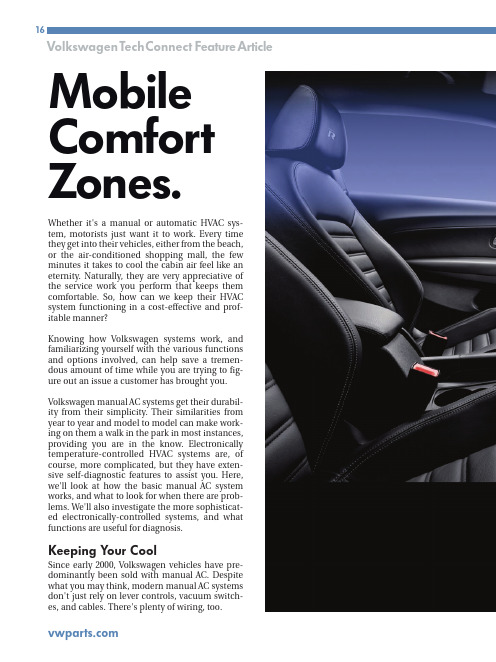
Whether it's a manual or automatic HVAC sys-tem, motorists just want it to work. Every time they get into their vehicles, either from the beach,or the air-conditioned shopping mall, the few minutes it takes to cool the cabin air feel like an eternity. Naturally, they are very appreciative of the service work you perform that keeps them comfortable. So, how can we keep their HVAC system functioning in a cost-effective and prof-itable manner?Knowing how Volkswagen systems work, and familiarizing yourself with the various functions and options involved, can help save a tremen-dous amount of time while you are trying to fig-ure out an issue a customer has brought you. Volkswagen manual AC systems get their durabil-ity from their simplicity. Their similarities from year to year and model to model can make work-ing on them a walk in the park in most instances,providing you are in the know. Electronically temperature-controlled HVAC systems are, of course, more complicated, but they have exten-sive self-diagnostic features to assist you. Here,we'll look at how the basic manual AC system works, and what to look for when there are prob-lems. We'll also investigate the more sophisticat-ed electronically-controlled systems, and what functions are useful for diagnosis.Keeping Y our CoolSince early 2000, Volkswagen vehicles have pre-dominantly been sold with manual AC. Despite what you may think, modern manual AC systems don't just rely on lever controls, vacuum switch-es, and cables. There's plenty of wiring, too.Mobile Comfort Zones.Manual AC systems are called that these days because there is no computer-controlled feed-back to adjust cabin temperature. The passengers simply set a temperature and the system puts out what it can to achieve it. Some electrical inputs are used to protect compressor operation. There is an ambient temperature sensor, a refrigerant pressure sensor, and coolant temperature sensor to make sure conditions are right to turn it on.Starting in the early 2000 model year, a cooling fan control unit monitors all these sensor inputs and manages the compressor clutch circuit as well as the cooling fans.With a manual system, all of these inputs need to be working properly to activate the compressor. If any input were to fail, the compressor clutch cir-cuit would open. Without a control unit with self-diagnostic capability, this means each input has to be checked using pin voltages. Whether you want to check the voltage signals at the cooling fan control unit, or each individual sensor, is up to you. The control unit is usually mounted on the driver’s side front frame rail. On a New Beetle,that would be under the battery tray, not all that easy to get to. Some cooling fan control units have strip-type fuses secured to the top, some do not, depending on the application.Testing InputConsider a 2002 J etta VR6 with manual AC. Itscoolant fan control unit has two connectors, oneA happy customer is a comfortable one. Y ouperform essential services to keep them rolling, but one indulgence they really enjoy is climate control.Here's how to keep them as comfortable in their vehicles as they are in their homes.four-pin, and a larger 14-pin. On the four-pin connector, you have the relay’s power supplies, a 6.0 millimeter solid Red in pin #1, and a 2.5mil-limeter R/Wtracer in pin #3. They should have battery voltage at all times. In pin #2 (a 2.5 mil-limeter R/W tracer) is the power supply out of the relay for low-speed fan operation. The final 6.0millimeter R/W tracer is the power supply output for the high-speed fan.The 14-pin connector is where the internal relays get activated, not only for the cooling fan, but also for the AC compressor clutch. Pin #6 is a Brown ground wire, and constant battery voltage comes in on pin #4, a R/Gr tracer. Power from the ignition switch comes in on in pin #9, usually a Bk/Bl tracer.In order for the compressor to turn on, inputs are needed. The first check is on pin #8, a Bl/R tracer. When the AC button is pressed and the blower is commanded on, you should see bat-tery voltage. Next, look at pin #2, a W wire. This is an unusual signal in that it is a five-volt square wave created by the refrigerant pressure sensor.The duty cycle of the signal will change with the refrigerant charge. This is to indicate if the charge is too low or too high to turn on/off and damage the compressor.Another signal that may inhibit compressor acti-vation is that of the ambient temperature switch. Test for voltage between pins #5 (Bl/R)and #14 (Gn/Bl). If the signal indicates the air temperature is too low, it will not allow the com-pressor to run. Check these inputs to the cooling fan control unit whenever the compressor clutch won't engage.A Brief Description of Climate ControlThe phrase "Automatic Climate Control" means that after setting the temperature in the cabin,an electronic unit monitors both outside and cabin temperature conditions and uses a pro-grammed plan for how best to achieve and maintain the chosen setting. These settings vary from full defrost heat to MAX AC. Once a tem-perature is set, the control unit will automatical-ly manipulate mode doors, temperature blend doors, and the recirculation door. There are manual overrides the passengers can select to control the mode doors' position, cabin air recirculation, and AC compressor operation.Since the electronics are overseeing system operation, Volkswagen has implemented the same self-diagnostic features found in other on-board control units.This is an ambient air temperature sensor found on an automatic climate control system, and is not to be confused with the ambient air temperature switch found on manual system. This sensor will only flag a code and affect temperature control. It will not suspend compressor operation.You may not realize what your current scan tool is capable of. You may not even realize how much useful information you have at your fin-gertips. You should hone your skills, reduce yourdiagnostic time and maybe get ahead of the “cost-effective diagnosis” game.Volkswagen/Audi Automatic Climate Controlled Systems are endowed with similar self-diagnostic features to powertrain control systems. While the scan-based diagnostic features in the Auto-HVAC systems are extensive, the interface is propri-etary, so without knowing what you are looking for it will be difficult to interpret the data being displayed. So how does this work?For those of you familiar with VAG scan-based diagnostics, this will be a review. For those not familiar with it, welcome to the future. VAG is the factory proprietary scan tool for Volkswagen and Audi vehicles. If you purchase the European bun-dle for your aftermarket scan tool, you should be able to display this “factory” software, which allows you to communicate with all of the various control units in the vehicle. Each control unit is programmed to use the same software architec-ture, so what we're about to describe will work onABS, as well as SRS.As you can see, there are many “address words”for all of the possible self-diagnostic systems on the vehicle. Select address word 08 – HVAC and you can talk to an automatic climate control sys-tem (not a manual system).The famous three dials of the Volkswagen HVAC system tell us when the AC button is pushed and the blow-er motor is turned on. The switch provides voltage to pin #8 on the cooling fan control unit indicating that AC has been requested.• Function 4 provides ‘basic settings.”• Function 5 clears codes.• Function 6 ends communication with the control unit.• Function 7 allows you to code the control unit to the particular car it is in.• Function 8 is for reading data.There are a few other functions to choose from,but we are going to focus on the most important ones.Starting with function 01, you will see that this merely identifies the control unit in the vehicle as well as its version coding. This information is useful if you feel the coding may have been changed in error, or a used control unit was installed and may not match the requirements of communicating with all of the other various con-trol units in the vehicle. Each control unit is pro-grammed to use the same software architecture,so what we're about to describe will work on ABSas well as SRS. You can enter the self-diagnosticOn the side of the cooling fan control unit, the pins are identified with their functions. You may be able to use them for testing once you learn what they are. Note that both strip and ATC fuses can be blown and prevent AC and cooling fan operation.You can enter the self-diagnostic feature with your scan tool by simply picking the address word you need. So, what’s an address word? With the factory scan tool, a series of numbers is used to identify the various systems we can enter. These numbers are called “address words” in your tech-nical literature.FunctionsEach system has its own address word. On the Volkswagen/Audi factory tester, you need to know what address word represents each system.Aftermarket diagnostic tools give the address word as well as a description of the system. In the case of automatic climate control, the address word is 08 (Auto – HVAC). Once you’ve selected the system, you will now be asked to select what function you would like to perform. You have numerous choices:• Function 01 identifies the control unit.• Function 2 is for pulling codes.• Function 3 is for actuation mode.feature with your scan tool by simply picking the address word.Providing the control unit is the proper one, you can correct coding if necessary. Function 02 is pretty self-explanatory. Auto-HVAC units are capable of self-diagnosis, and can identify faults in one or more components. These com-ponents are either sensor inputs, or actuator outputs. In the case of actuator outputs, you don't always have to access the component and start our testing there. The other option is scan tool activation.Function 03 is the mode in which you can take advantage of the scan tool and request that the HVAC control unit activate various outputs. You can listen for the activation, and/or perform elec-trical testing on the component being activated. This allows you to verify that the control unit’sdriver is capable of turning on any component in which you may suspect a fault.Moving along to function 04, this is referred to as “Basic Settings.” In general, this provides a “reset” or ‘re-sync” of computer-controlled fea-tures. The automatic climate control system needs to know the positions of the various tem-perature and mode doors in order to manipulate them if a change is requested by the occupant, or sensed by a temperature sensor. "Basic Settings" runs the control unit through the re-learn process, but more on this later.Function 05 simply clears codes, and once you are done communicating with the HVAC control unit, you need to shut down this communication by selecting Function 06. This prevents corrup-tion of software in the unit. Function 07 allows you to change the version coding, which is a way for you to tailor the control unit to the vehicle it is in. Vehicles come with more than one option. Each control unit must be made aware of these options in order to perform properly. This comes in especially handy when installing used parts. Although the replacement control unit may have the same part number, the coding must be changed to accommodate the requirements of the vehicle being repaired.Finally, Function 08 (sometimes referred to as data blocks, or measuring blocks) allows you to look at data, such as a temperature sensor read-ing, or actuator position. The tricky part is that these data blocks are also identified with num-bers and are displayed in blocks of four. You must look up in a table what the data blocks indicate for each display group.ResetOnce you have pulled codes, diagnosed a prob-lem, and done a repair, you may need to reset the climate control system, especially if a mode door motor was replaced. This can be achieved through the “Basic Settings” feature. You will be prompted to enter a three-digit code. Leave the code "000" in the display and enter this mode. The positions of the doors are recorded, and they will then cycle to their respective end stops. Now, the control unit knows what the maximum and minimum positions are for each mode/blend door. When it needs to make a temperature adjustment as a result of changing conditions, it can make the cor-rect change. Without knowing the proper position of the doors, it will make the wrong adjustment and output the wrong temperature.Knowing the system helps cut down on wasted diagnostic time, and can make you money on all but the most difficult problems. You will end up with fewer comebacks, less stress, and a cool,happy customerHere are your options once you have selected an address word. In 08, you can select “Basic Settings,” enter “000,” and the system will run through the initialization process. This should be performed after every mode door and tempera-ture blend door replacement.。
ISPE+HVAC翻译(part1) (优选.)rd1 INTRODUCTION 简介111.1B ACKGROUND 背景111.2S COPE OF T HIS G UIDE 指南范围111.3O BJECTIVES OF T HIS G UIDE 指南目的121.4D EFINITIONS 定义131.5R EFERENCES 参考文献132. FUNDAMENTALS OF HVAC 空气净化系统的基本原则172.1I NTRODUCTION 简介172.2W HAT IS HVAC?172.2.1 People comfort 人员的舒适182.2.2 Product and Process Considerations产品与工艺注意事项202.2.3 How does the HVAC system control these parameters? 空气净化系统如何控制这些参数?212.2.4 What can’t the HVAC System do? 空气净化系统不能做什么?212.3A IRFLOW FUNDAMENTALS气流基本原则222.3.1 Introduction简介222.3.2 Ventilation Fundamentals通风基本原则222.3.3 Contamination Control污染控制222.3.4 Airlocks气闸232.3.5 Classified Space 分类空间232.3.6 Total Airflow Volume and Ventilation Rate总风量与通风率252.3.7 Room Distribution and Quality of incoming air房间布局和进气质量272.3.8 Airflow Direction and Pressurization气流方向与增压272.4P SYCHROMETRICS 湿度测定法282.4.1 Introduction简介282.4.2 Basic Properties of Air空气的基本性质292.4.3 Psychrometric Properties of Air空气的湿度性质292.5E QUIPMENT 设备302.5.1 Introduction 简介302.5.2 Air Handing Unit (Ahu) 空气处理单元312.5.3 Fan风机312.5.4 Fume Exhaust/ Extraction System烟尘排除系统312.5.5 Heating Coil加热旋管312.5.6 Cooling Coil 冷却盘管312.5.7 Humidifier 增湿器312.5.8 Dehumidifier 除湿器312.5.9 Air Filtration 空气过滤器312.5.10 Ductwork 管道系统322.5.11 Damper And Louver 风门和天窗322.5.12 Diffuser and Register 扩散器和调风器322.5.13 Ultraviolet (UV) Light 紫外灯322.6HVAC SYSTEM CONFIGURATION HVAC系统配置332.6.1 Introduction 简介332.6.2 Basic System Types 基本系统类型342.6.3 Air Handling Unit Configurations空气处理单元的构造372.6.4 AIRLOCK STRATEGIES 气闸方案412.6.5 Ventilation/supply strategies 通风/供风方案462.6.6 EXTRACT (EXHAUST AND / OR RETURN) STRATEGIES 抽气(排气和回风)方案48 2.6.7 DISTRIBUTION 分布482.7HVAC CONTROLS AND MONITORING HVAC控制与监测482.7.1 Introduction 简介482.7.2 Controls 控制492.7.3 Actuation methods 驱动法502.7.4 Instrumentation 测量仪表522.7.5 Environmental Monitoring 环境检测572.7.6 Equipment monitoring 设备监测602.8SYSTEM ECONOMICS系统经济612.8.1 Introduction 简介612.8.2 Life Cycle Cost Analysis 生命周期成本分析632.8.3 User Requirements Specification 用户要求说明662.8.4 Life Time Operating Costs 寿命运行成本682.8.5 Comparing Options 对比选择682.9SUSTAINABILITY(TO BE WRITTEN LATER)可持续性(以后再写)错误!未定义书签。
3.14 Single-machine commissioning, system commissioning and jointc o m m i s s i o n i n g3.14 单机调试、系统调试、联动调试3.14.1 Overall plan of commissioning3.14.1 调试总体策划Commissioning work is divided into three stages, which is shown in the figure 3.14.1-1.调试工作分为三个阶段,见图3.14.1-1。
Figure 3.14.1-1 Commissioning work图3.14.1-1 调试工作Commissioning work of the project mainly includes implementation and management of commissioning of HVAC works, commissioning of electrical works, commissioning of plumbing as well as commissioning of fire fighting works.本工程系调试工作主要包括通风空调工程调试、电气工程调试、给排水及消防工程调试实施及管理工作。
1. Commissioning indispensable conditions are shown in the table 3.14.1-1.1、调试具备条件见表3.14.1-1。
Table 3.14.1-1 Commissioning indispensable conditions表3.14.1-1 调试具备条件No.序号Name ofsystem系统名称Preparatory work before commissioning调试前的准备工作1 Electricalsystem电气系统Installation of electrical equipment is completed. Laying of bridge, medium& low voltage cables and busbar is completed; wiring of secondary controlcables is right as per drawings. Installation of power and lightingswitchboard is completed; installation and wiring of power equipment arecompleted; appearance check is qualified. Wiring of various lamps iscompleted. Wiring of various switch panels is completed.电气设备安装完毕。
测控技术导论课程报告学院名称专业名称学生姓名学生学号任课教师设计(论文)成绩教务处制2018年12月15日测控技术与仪器专业导论读书报告如今,随着科技的迅猛发展,测控技术在众多专业中突显出了重要性。
在融合了各种学科后,测控技术渗透到了各个行业与领域,也发挥着不可或缺的作用。
我通过阅读相关书籍,对于测控专业也有了更深入的了解。
测控专业的发展现状目前,测控专业的前景势态良好,与实际的工业生产联系相当密切。
主要是因为它不仅能用运用在电子技术,也可以用于通信、网络技术、光电和其他方面,这在很大程度上提高了测量与控制领域的发展。
综上所述,如今测控专业已经发展成一个高新综合型电子技术类专业,作为工科专业,对于动手能力也有着一定的要求。
二十一世纪,电子测控技术迎来了新的发展机遇。
测控技术数字化已成为当今发展的趋势。
数字传输是当今发展的热点之一,测控技术也不例外。
目前测控技术的数字化主要体现在测控技术的多媒体数字化、测控技术中传感器的数字化、传输与控制技术的数字化三个方面。
测控技术的数字化使其电子应用技术更加方便实用,为人们解决生产和生活中需要解决的问题提供了方便。
对于测控专业的了解,首先要了解该专业所包含的学科:模拟电子技术、数字电子技术、单片机原理、测控技术与系统、测控仪器设计、控制工程基础、精密机械制造工程、工程光学基础、传感器等等,其中可知,测控技术专业学习的难度和广度。
如何介绍测控技术与仪器这个专业,顾名思义:包括测量、控制以及精密仪器的使用。
测控技术如今与现代电子技术相结合发展,使得测控技术迎来了发展的新的潮浪。
科技与文化是一个国家的软实力。
在世界各个国家竞争越来越激烈的今天,科技的较量也就从一个侧面反映出一个国家的国力是否强盛。
只有科技发达,国家的国力才会增强,才会从各个方面带动产业的发展,推动产业升级。
而测控技术恰恰就是精尖科技的一个缩影。
它不仅包括了测量和控制双重的技术,同时还综合了电子数字技术,提升了测控技术的精准度和科技含量。