真空玻璃期刊7
- 格式:pdf
- 大小:897.78 KB
- 文档页数:7
随着科技日新月异的发展,人们的居住环境也在逐步改善与提高。
其实从2000年开始国内大量使用中空玻璃,最近几年又悄然兴起它的升级替代品——真空玻璃。
小编为您带来有关真空玻璃的相关知识。
一、真空玻璃的前世今生实际上真空玻璃出现已经很久了。
早在1893年,英国物理学家、化学家占姆士•杜瓦发明了保温瓶(开水瓶/暖水壶,别说你没用过),就是用的是真空原理。
而平板真空玻璃在1913年就出现了专利申请。
但直到1990年代美国克罗拉多太阳能研究所的Benson教授和澳大利亚悉尼大学Collins教授,推动下产生了一系列应用技术和相关专利。
真空玻璃才在建筑、冰柜等一些场景下开始使用。
1990年,在北京大学物理系教授唐健正,作为访问学者来到悉尼大学,开始与该校时任应用物理系主任的Collins教授联合研究平板真空玻璃。
经过3年的努力,1993年世界上首块1米×1米的平板真空玻璃样品问世。
但发明人虽是Collins和唐健正,但专利权明显属于悉尼大学。
1996年,悉尼大学把专利转让给日本板硝子,日本人在次年即开始量产真空玻璃。
后来唐健正教授回国后继续了研究,1998年建立北京真空玻璃研究所、青岛新立基真空玻璃技术应用有限公司等,并申请了中国专利。
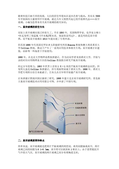
二、真空玻璃原理和特点简单来说,真空玻璃就是把两片平板玻璃四周密闭,将其间隙抽成真空,两片玻璃之间的间隙为0.1-0.2mm,真空度可以做到0.1帕以上。
由于需要抵抗空气中的大气压,真空玻璃的两片玻璃之间分布着陶瓷支柱。
真空玻璃相对与中空玻璃,少了空腔中的气体,因此少了对流传热,K值可以做到1w/㎡•k甚至更低,比中空的效果更好。
隔音也可以做到30分贝以上,基本和中空玻璃相当。
跟中空玻璃一样,真空玻璃也可与镀膜、钢化、夹层甚至钻孔工艺叠加,解决红外热辐射,强度和安全性等问题。
事实上关于真空玻璃,早已经有了国标JC/T1079-2008《真空玻璃》。
三、真空玻璃发展的瓶颈实际上经过几十年的发展,真空玻璃早已经不是什么实验室的黑科技。
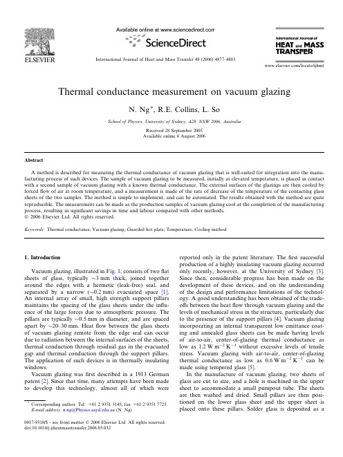
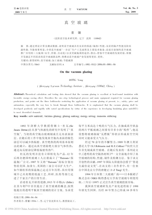
Thermal conductance measurement on vacuum glazingN.Ng *,R.E.Collins,L.SoSchool of Physics,University of Sydney,A28,NSW 2006,AustraliaReceived 28September 2005Available online 8August 2006AbstractA method is described for measuring the thermal conductance of vacuum glazing that is well-suited for integration into the manu-facturing process of such devices.The sample of vacuum glazing to be measured,initially at elevated temperature,is placed in contact with a second sample of vacuum glazing with a known thermal conductance.The external surfaces of the glazings are then cooled by forced flow of air at room temperature,and a measurement is made of the rate of decrease of the temperature of the contacting glass sheets of the two samples.The method is simple to implement,and can be automated.The results obtained with the method are quite reproducible.The measurement can be made as the production samples of vacuum glazing cool at the completion of the manufacturing process,resulting in significant savings in time and labour compared with other methods.Ó2006Elsevier Ltd.All rights reserved.Keywords:Thermal conductance;Vacuum glazing;Guarded hot plate;Temperature;Cooling method1.IntroductionVacuum glazing,illustrated in Fig.1,consists of two flat sheets of glass,typically $3mm thick,joined together around the edges with a hermetic (leak-free)seal,and separated by a narrow ($0.2mm)evacuated space [1].An internal array of small,high strength support pillars maintains the spacing of the glass sheets under the influ-ence of the large forces due to atmospheric pressure.The pillars are typically $0.5mm in diameter,and are spaced apart by $20–30mm.Heat flow between the glass sheets of vacuum glazing remote from the edge seal can occur due to radiation between the internal surfaces of the sheets,thermal conduction through residual gas in the evacuated gap and thermal conduction through the support pillars.The application of such devices is in thermally insulating windows.Vacuum glazing was first described in a 1913German patent [2].Since that time,many attempts have been made to develop this technology,almost all of which werereported only in the patent literature.The first successful production of a highly insulating vacuum glazing occurred only recently,however,at the University of Sydney [3].Since then,considerable progress has been made on the development of these devices,and on the understanding of the design and performance limitations of the technol-ogy.A good understanding has been obtained of the trade-offs between the heat flow through vacuum glazing and the levels of mechanical stress in the structure,particularly due to the presence of the support pillars [4].Vacuum glazing incorporating an internal transparent low emittance coat-ing and annealed glass sheets can be made having levels of air-to-air,center-of-glazing thermal conductance as low as 1.2W m À2K À1without excessive levels of tensile stress.Vacuum glazing with air-to-air,center-of-glazing thermal conductance as low as 0.6W m À2K À1can be made using tempered glass [5].In the manufacture of vacuum glazing,two sheets of glass are cut to size,and a hole is machined in the upper sheet to accommodate a small pumpout tube.The sheets are then washed and dried.Small pillars are then posi-tioned on the lower glass sheet and the upper sheet is placed onto these pillars.Solder glass is deposited as a0017-9310/$-see front matter Ó2006Elsevier Ltd.All rights reserved.doi:10.1016/j.ijheatmasstransfer.2006.05.032*Corresponding author.Tel.:+61293513145;fax:+61293517725.E-mail address:n.ng@.au (N.Ng)./locate/ijhmtInternational Journal of Heat and Mass Transfer 49(2006)4877–4885liquid slurry along the edges of the glass sheets.The pum-pout tube is placed in the hole in the upper sheet,and sol-der glass is also deposited around this tube.A differentiallypumped,all metal evacuation cup is positioned on the glass before the high temperature edge sealing process [6].The assembly is then heated to approximately 480°C.At this temperature,the solder glass melts and flows by capillary action into the small gap between the glass sheets,forming the hermetic edge seal.The sample is then evacu-ated,and the internal surfaces are outgassed.This process commences as the sample cools following the formation of the edge seal,when the solder glass has solidified suffi-ciently that it is not forced by atmospheric pressure intothe gap between the glass sheets.At the completion of the outgassing process,the pumpout tube is sealed as the sample cools towards room temperature.In the manufacturing process of vacuum glazing,it is important to measure the thermal conductance of each device in order to verify that it meets the product specifica-tion.Two different methods have been described for making such measurements.In one method,a guarded hot plate apparatus is used to measure the heat flow through a well-defined area of the sample of vacuum glazing [7].In this method,a thermal conductor,referred to as the metering piece,is placed in good thermal contact with one surface of the glazing.The metering piece is sur-rounded on its external surfaces by a thermal guard at a well-defined temperature.The thermal guard is also in good contact with the surface of the glass sheet.The other side of the sample is maintained at a lower temperature.Electrical power is dissipated in the metering piece,and the power level is adjusted until the temperature of the metering piece is precisely the same as that of the guard.When this condition is established,all of the power being dissipated in the metering piece flows through the sample.Because the area of the metering piece is known,this method provides an absolute measurement of the thermal conductance of the sample.In one application of this method to vacuum glazing,the area of the metering piece was made very small ($1cm 2)in order to provide separate measurements of the heat flow through the evacuated gap in the sample,and that due to thermal conduction through the support pillars [7].In another previously described method of measuring the thermal conductance of vacuum glazing,a rapid temperature increase is applied to the glass sheet on one side of the sample [8].A measurement is then made of the subsequent relatively small,slow rate of increase of the temperature of the glass sheet on the other side.InNomenclature A area (m 2)a pillar radius (m)C thermal conductance (W m À2K À1)c specific heat (J K À1kg À1)k thermal conductivity (W m À1K À1)_Q rate of heat flow (W)T temperature (°C)D T temperature difference (°C)Taverage temperature (°C)Greek symbols b roughness factor e emittance k pillar separation (m)h temperature (°C)q density(kg m À3)r Stefan Boltzmann constant(5.67Â10À8W m À2K À4)stime constant (s)Subscriptsa ambient g glass h hot o outer i inner s standard sample t test sample x ,y internal surfaces of glass sheets 1,2first and second stages of cooling vac vacuumthe application of this method to vacuum glazing,the tem-perature sensor is located at the center of a unit cell of the pillar array.The measurement therefore characterises the thermal conductance associated with heat transfer through the evacuated space.This thermal conductance is propor-tional to the initial rate of temperature increase of the glass sheet at this point,and inversely proportional to the ther-mal mass of this sheet.Both of these methods can be used with larger detection areas to provide measurements of the total thermal con-ductance of vacuum glazing due to the combined heatflow through the evacuated gap and the pillars.Such large area measurements have also been made with conventional heat flow meters,in which the thermal conductance is deter-mined from the temperature drop across a known thermal resistance that is in series with the heatflow through the sample.Each of these measurement processes typically takes many tens of minutes to perform.In addition,because they involve the measurement of very small temperature changes,the temperatures within the measuring apparatus and the test sample must be very stable before the measure-ment commences.During the manufacture of vacuum glaz-ing,the samples to be tested are sealed and available for measurement when their temperature is significantly above ambient,and is decreasing rapidly.If these methods are used in the production process,it can therefore typically take many tens of minutes,and up to an hour,after sealing of the pumpout tube before the temperatures in the sample and measuring apparatus are sufficiently stable for a mea-surement to commence.These methods are thus not partic-ularly suitable for use in a high-volume vacuum glazing production process.This paper describes a method of measuring the thermal conductance of vacuum glazing that is well suited for inte-gration into the vacuum glazing production process.The measurement is performed as the samples cool after com-pletion of the high temperature evacuation and bakeout process.The integration of the measurement into a neces-sary cooling phase of the production process can signifi-cantly reduce the overall production time for the glazing.2.Heatflow through vacuum glazingAs noted above,heatflow between the glass sheets of vacuum glazing remote from the edge seal can occur due to radiative heat transfer between the internal surfaces of the sheets,thermal conduction through the support pillars, and thermal conduction through residual gas in the inter-nal evacuated space[9].Additional heatflow can occur in the vicinity of the hermetic edge seal due to lateral thermal conduction along the glass sheets[10],but this is not con-sidered in the following analysis.As for conventional insulating glazing,in the practical application of vacuum glazing,the overall rate of air-to-air heatflow through the glazing is significantly influenced by heat transfer processes between the external surfaces of the glass sheets and the surrounding environment.To a very good approximation for both internal and external heat transfer processes,the rate of heatflow_Q through area A is proportional to A and to the temperature differ-ence D T associated with the specific process.The heatflow can therefore be written in terms of a thermal conductance C for the specific process_Q¼CA D T:ð1ÞThe thermal conductance associated with radiative heat flow between the internal surfaces of the glass sheets can be writtenC radiation¼4e effective r T3;ð2Þwhere r is the Stefan Boltzmann constant(5.67Â10À8 W mÀ2KÀ4),T is the average temperature of the two glass sheets,and e effective is the effective emittance of the glass sheets.To a good approximation,the effective emittance can be written1e effective¼1e xþ1e yÀ1;ð3Þwhere e x and e y are the hemispherical emittances of the internal surfaces of the two glass sheets.The thermal conductance associated with heatflow between the glass sheets due to thermal conduction through the array of support pillars is given by[11]C pillars¼2b ka=k2;ð4Þwhere k is the thermal conductivity of the glass sheets (1.0W mÀ1KÀ1for soda lime glass),and a and k are respectively the radius and separation of the pillars.For a smooth pillar,the contribution of the pillar to the overall glass-to-glass thermal conductance is determined by the spreading resistance associated with the heatflow in the glass sheets close to the pillar.In some designs of vacuum glazing,however,the surfaces of the support pillars that contact the glass sheets are rough.The heatflow through a rough pillar is less than for a smooth pillar of the same diameter due to the additional contact resistance associated with non-uniformities in the heatflow in the immediate vicinity of the rough pillar.A factor b(termed the rough-ness factor here)is included in Eq.(4)to allow for this effect.Most of the samples of vacuum glazing used in this work contain smooth pillars(b=1)in order to avoid the uncertainties associated with the measurement of b.How-ever,data are also presented below for samples that con-tain rough pillars.The roughness factor for these pillars was determined by constructing an experimental sample containing both rough and smooth pillars.The small area guarded hot plate apparatus was positioned directly above individual rough and smooth pillars,and the heatflow through the metering piece was measured.There are two contributions to this heatflow:thermal conduction through the pillar,and radiation between the glass sheets. The heatflow due to radiation only was measured by positioning the metering piece of the apparatus over aN.Ng et al./International Journal of Heat and Mass Transfer49(2006)4877–48854879pillar-free region of the sample.The radiative heatflow was subtracted from the heatflow in the vicinity of the pillars to obtain the amount of heatflow thatflows through the metering piece of the guarded hot plate apparatus due to the pillar only.The value of b is equal to the ratio of the measured heatflows through rough and smooth pillars, adjusted for the different diameters of the pillar surfaces that contact the glass sheets.There are significant varia-tions(±10%)in the measured values of b for nominally identical pillars,so several pillars were measured to obtain an average value of the roughness factor.The results of these measurements are reported below.At low pressures,the heatflow through residual gas in the evacuated space is proportional to the pressure of the gas,and this heatflow can be characterised by a glass-to-glass thermal conductance C gas.In well made glazing,C gas is negligible.The glass-to-glass,center-of-glazing thermal conduc-tance that characterises the total heatflow through the glazing C total is obtained simply by adding the thermal con-ductances associated with heatflow due to radiation,gas conduction,and through the support pillars.This thermal conductance can be writtenC total¼C radiationþC pillarsþC gas:ð5Þ3.Principle of the measurement methodWhen this method is integrated into the vacuum glazing manufacturing process,the measurement of the sealed pro-duction samples of vacuum glazing takes place immediately after they leave the hot bake out oven.In order to prevent breakage of the glass sheets due to temperature-induced stresses,the temperature of the samples is normally no greater than about70°C at this time.The hot sample of vacuum glazing having total(unknown)glass-to-glass ther-mal conductance C t(referred to here as the Test sample),is initially at a temperature T h.This sample is placed in con-tact with a second sample of vacuum glazing of(known) thermal conductance C s(referred to as the Standard sam-ple).The outer glass sheets of the two samples are then cooled rapidly by forced air convection,and a measure-ment is made of the much slower rate at which the temper-ature of the contacting glass sheets of the two samples T g decreases towards ambient temperature T a.The rate at which this temperature decreases can be related to the ther-mal conductance of the two samples,and to the thermal conductance associated with heat transfer between the surfaces of the external glass sheets of the two samples and the surrounding air.The configuration of the samples during the measure-ment is illustrated schematically in Fig.2.Afine thermo-couple is located between the two contacting glass sheets of the Test sample and the Standard sample.In practice, the thermocouple would normally be attached to the Stan-dard sample.Following the positioning of the room tem-perature Standard sample on the hot Test sample,the temperatures of the two contacting glass surfaces equalize to a value close to the mean of their initial temperatures, and remain essentially equal throughout the remainder of the measurement.This thermocouple therefore measures the temperature of these glass sheets T g.The temperature of the external glass sheet of the Stan-dard sample T s is measured with a second thermocouple that is attached to this sheet.In the measurements pre-sented here,an additional thermocouple is attached to the external glass sheet of the Test sample to measure the temperature of this sheet T t.This thermocouple is not nec-essary in order to obtain the thermal conductance of the Test sample and need not be present when the method is used in a vacuum glazing production line.The satisfactory operation of this method is critically dependent on being able to establish a thermal conduc-tance associated with heat transfer between the external surfaces of the glass sheets and the surrounding air C g–a that is much greater than C s or C t.As will be seen,this is readily achieved if air at ambient temperature is blown across the external surfaces of the Test sample and the Standard sample with a fan.The temperature T a of this air is also measured using a thermocouple located at some convenient position.In the following analysis,it is assumed that the Standard sample is made from glass sheets that have thickness t s,i and t s,o,and the Test sample from sheets of thickness tt,iand t t,o,where the subscripts i and o refer to the inner(con-tacting)and outer sheets,respectively.The samples are made from soda-lime glass which has a density q=2470kg mÀ3,and specific heat c=(813+1.67h) J KÀ1kgÀ1where h is the temperature of the glass in°C.Because of theflowing air,the thermal conductance C g–a associated with heat transfer between the external surfaces of the glass sheet of the hot Test sample and the surround-ing air is very large compared with that which would occur due to cooling by radiation and natural convection alone. The temperature of this glass sheet therefore decreases rapidly.If C g–a is constant,the time dependence of this temperature decrease towards its steady state value is nearly exponential for thefirst few minutes when the temperature T g of the contacting glass sheets is approxi-mately constant.The time constant s1for thisfirst rapid temperature decrease is the product of the thermal resis-tance per unit area associated with convective heat transfer to theflowing air1/C g–a,and the thermal capacity per unit area of the outer glass sheet of the Test sample q ct t,os1¼q ct t;o=C g–a:ð6ÞWith forced air circulation,it is straightforward to achieve a thermal conductance between the external surface of the glass sheets and the air C g–a in excess of30W mÀ2KÀ1. For3mm thick glass,such a thermal conductance results in a time constant for cooling of the external glass sheet of the Test sample of approximately200s.Approximately5s1after placing of the Standard sample on the Test sample,most of the heat initially present in the external glass sheet of the Test sample has been lost to the circulating air.The temperature of this sheet is thus close to the ambient temperature.Most of the remaining heat in the assembly is in the contacting glass sheets of the Standard and Test samples.At this time,the measurement of the thermal conductance of the Test sample commences.In order to obtain accurate results with this method,it is essential that the only significant heat losses from the con-tacting regions of the glass sheets are due to heatflow through the evacuated space and support pillars of the Standard and the Test samples to the external glass sheets of these samples,and from these sheets to the surround-ings.There are two other possible sources of heat loss that can lead to errors in the measurement:heat transfer to air flowing in the small gap between the contacting glass sheets,and lateral heatflow along the glass sheets.The size of the gap between the glass sheets is determined by the diameter of the wires of the thermocouple used to measure T g,and also by any residual departures from planarity of the samples.In this work,experiments in which the two glass sheets were taped together around the edges have demonstrated that heat loss due to airflow between the two samples is negligible.It is also necessary for the lateral heatflow along the contacting regions of the glass sheets to be reduced to neg-ligible levels.This can be achieved by positioning the ther-mocouple that measures T g sufficiently far from the edges of the samples.In this work,the appropriate location of this thermocouple was determined by making measure-ments of the time dependence of the temperature of the contacting glass sheets at different distances from the edge seal of the sample.For glazings made from3mm thick glass,it was found that the thermocouple that measures T g must be at least80mm from the edge seal in order that effects due to lateral heatflow along the glass sheets are negligible.Fig.3shows the thermal equivalent circuit that is used to calculate the time dependence of the temperatures in the system during the slow cooling of the contacting glass sheets.The thermal capacity per unit area of the two con-tacting glass sheets is q c(t t,i+t s,i).The thermal resistance per unit area associated with heatflow from these glass sheets through the Standard sample to theflowing air is given by the series combination of the thermal resistance per unit area1/C s for heatflow through the evacuated space and pillars of this sample,and the thermal resistance per unit area1/C g–a associated with heat transfer from the external surface of the glass sheet to the surrounding air: 1/C s+1/C g–a.Similarly,the thermal resistance per unit area associated with heat transfer from the contacting glassN.Ng et al./International Journal of Heat and Mass Transfer49(2006)4877–48854881sheets through the Test sample is 1/C t +1/C g–a .The total thermal resistance per unit area associated with cooling of the contacting glass sheets is the parallel combination of these two thermal resistances.For times greater than $5s 1,the temperature of the two contacting glass sheets T g decreases exponentially towards ambient temperature T a ,since all of the thermal resistances are independent of time.The time constant s 2for this expo-nential temperature decrease during this second stage of cooling is given by the product of the thermal capacity per unit area of the two glass sheets and the total thermal resistance per unit area associated with the heat loss from these glass sheets to the surroundingss 2¼ðt s ;i þt t ;i Þq c ½ Âð1=C s þ1=C g –a ÞÀ1þð1=C t þ1=C g –a ÞÀ1h i À1:ð7ÞThis equation can be rewritten to obtain the thermal con-ductance of the Test sampleC t ¼ððt s ;i þt t ;i Þq c =s 2Àð1=C s þ1=C g –a ÞÀ1ÞÀ1ÀðC g –a ÞÀ1h i À1:ð8ÞAll of the quantities in this equation are known except thethermal conductance associated with heat transfer between the external surfaces of the glass sheets and the surround-ing air C g–a .This quantity can be simply determined from Eq.(6)if a thermocouple is attached to the external surface of the Test sample.Alternatively,C g–a can be determined from a measurement of the temperature of the external sur-face of the Standard sample during the second slow cooling phaseC g –a ¼C s ðT g ÀT s Þ=ðT s ÀT a Þ:ð9ÞIn practice,C g–a may be calculated continuously from Eq.(9)during the measurement to confirm that this quantity remains constant throughout the cooling period.The thermal equivalent circuit in Fig.3does not include the effect of the thermal capacities of the outer glass sheets that are in parallel with the thermal resistances associated with heat transfer from these sheets to the flowing air.A straightforward equivalent circuit analysis of this system shows that the error introduced by ignoring these thermal capacities is less than 1%.The thermal equivalent circuitalso ignores transient effects associated with the distributed thermal capacity and thermal resistance through the thick-ness of the glass sheets.The characteristic time for the tem-peratures through the thickness of these sheets to equalise is $10s.This is at least 100times less than the time constant for the exponential temperature decrease of the contacting glass sheets so,again,ignoring these effects introduces negligible errors into the results obtained using the method.In the above analysis,it is assumed that the tempera-tures of the glass sheets are uniform in the regions where the Standard sample is in contact with the Test sample.Strictly speaking,this is not the case because of the local-ised heat flow through the support pillars.The magnitude of the temperature non-uniformities that occur due to such heat flow depends on the amount of heat that flows through each pillar,and the external thermal conductance [11].These temperature non-uniformities are usually less than about 0.5°C,for typical experimental conditions likely to occur in this measurement.While this is quite small,the quantity T s ÀT a in Eq.(9)is only a few °C.Sig-nificant errors could therefore occur in the value for C g–a obtained from Eq.(9).However,most of these temperature non-uniformities occur very close to each support pillar.The magnitude of the error in C g–a can therefore be reduced by locating the tip of the thermocouple that mea-sures the temperature T s at the center of a unit cell of the pillar array.In any case,the external heat transfer coeffi-cient C g–a has only a small effect on the value obtained for the thermal conductance of the Test sample C t .It is therefore possible to ignore effects associated with the tem-perature non-uniformities on the external surfaces of the glass sheet of the Standard sample without introducing significant errors in the measured value of thermal con-ductance of the Test sample.4.Experimental measurementsExperiments have been performed in order to validate the above analysis.In these experiments,custom-built samples of vacuum glazing are used as Standard and Test samples.The relevant dimensions of these samples are given in Table 1.Chromel–alumel thermocouples made from wire,0.2mm in diameter (including the thickness of the insulation)areTable 1Properties of Standard and Test samplesPillarseparation k (mm)Mean pillar diameter 2a (mm)Pillar typePillarconductance from Eq.(4)(W m À2K À1)Measured vacuum conductance at 13°C(W m À2K À1)Gas conductance (W m À2K À1)Vacuum conductance at 35°C from Eq.(2)(W m À2K À1)Totalconductance at 35°C from Eq.(5)(W m À2K À1)Standard sample A 250.57Smooth (b =1.0)0.910.820 1.06 1.97Standard sample B 200.57Rough (b =0.76) 1.080.820 1.06 2.14Test sample A 250.57Smooth (b =1.0)0.910.820 1.06 1.97Test sample B 200.57Rough (b =0.76) 1.080.890.071.122.204882N.Ng et al./International Journal of Heat and Mass Transfer 49(2006)4877–4885attached close to the centre of both surfaces of the Standard sample to measure T g and T s.The tips of the thermocouples are located at the mid-point of a unit cell of the pillar array. In some experiments,several thermocouples are used to measure the temperature of the glass sheets at different dis-tances from the edge seal.In the measurements presented here,the temperature T t of the outer glass sheet of the Test sample is measured with an additional thermocouple that is attached to this sheet.In this experiment,air isflowing past the surfaces of the glass sheets on which the thermocouples arefixed.In the presence of such airflow,heat transfer between the thermo-couple and the air may result in large errors in the mea-sured temperatures T s and T t of these glass sheets, because of temperature gradients in the vicinity of the tip of the thermocouple.In order to obtain accurate tempera-ture measurements,it is therefore essential that10–20mm of the thermocouple wires adjacent to the tip of each ther-mocouple is in very good thermal contact with the surface of the sheets.In the experiments reported here,the thermo-couples arefixed to the surfaces of the glass sheets with adhesive tape.This problem does not exist for the thermo-couple between the contacting glass sheets that measures T g because it is not exposed to theflowing air.The thermal conductances associated with radiative heat flow and gaseous conduction through the evacuated space C vac of the Standard samples and the Test samples were independently measured using the small area guarded hot plate apparatus referred to above[7].The effective area of this apparatus was determined by measuring the rate of radiative heatflow between uncoated soda lime glass sheets in a dynamically pumped sample.This heatflow is known to very high accuracy by integration of the infrared reflectance of the glass over all relevant wavelengths and angles for radiative heat transfer between the sheets[12]. The measurements of vacuum conductance made with this apparatus have been demonstrated to be accurate to about ±1%.In the measurements of vacuum conductance,the meter-ing piece of the guarded hot plate apparatus was positioned at the centre of a pillar-free region for the custom-built samples,or at the centre of a unit cell of the pillar array for the some samples without a pillar-free region.In calcu-lating the vacuum conductances for samples without a pil-lar-free region,corrections were made for the small amount of heatflow through the nearby pillars that passed through the1.72cm2area of the metering piece of the guarded hot plate.The correction factor was determined by modelling the spatial distribution of the heatflow due to a single pil-lar at the external surface of the glass sheets.These model-ling results were validated by measuring the heatflow in the centre of a unit cell of the pillar array in otherwise identical experimental samples of vacuum glazing that also had a pillar-free region for accurate measurement of the vacuum conductance.The guarded hot plate measurements of the vacuum conductance were made at a mean temperature of13°C.For gas-free samples,these conductances were scaled to the value at the average sample temperature during the cool-down measurement by multiplying them by the ratio of the cube of the respective absolute temperatures T3, according to Eq.(2).For gassy samples,only the radiative component of C vac was scaled.The glass-to-glass conduc-tance of the pillar array C pillars was calculated from Eq.(4)using measurements of the diameter of the contact areas of several of the pillars in each sample.For the samples with rough pillars,the roughness factor b was determined as described above.The total glass-to-glass thermal con-ductance of these samples C total was calculated from Eq.(5)by adding the scaled vacuum conductance and the pillar conductance.The estimates of thermal conductance of the samples used in these experiments are presented in Table1.The glass sheets in all samples are2.9mm thick.All samples contain one internal pyrolytic low emittance coat-ing.The value of the hemispherical emittance of this coat-ing,determined by measuring the radiative heatflow in the pillar free region of a dynamically pumped sample,is0.17. The vacuum conductance of most of the samples discussed here is close to that expected for radiative heat transfer only,indicating that the internal vacuum in these samples is quite high.The Test sample is heated in an oven to approximately 70°C.This sample is then removed from the oven and mounted horizontally,with approximately90mm space above and below to permit the freeflow of air.A Standard sample is then placed onto the upper surface of the Test sample,and forced airflow commences.In these experi-ments,the airflow is driven by a150W commercial fan, approximately0.5m in diameter,located about2.5m from the edge of the sample onto which the airflows.The veloc-ity of the airflowing past the samples was measured with a commercial meterological wind gauge,and is approxi-mately5m sÀ1in the experiments described here.A data logger is used to record the temperatures of the samples, and the temperature of theflowing air,as a function of time after commencement of the forcedflow of air.Fig.4shows typical experimental measurements of the temperatures of the samples as they cool down with air flowing throughout the entire measurement.In order to demonstrate the functional dependence on time of these data,they are presented as both linear,and logarithmic plots.In all of these data,the temperature of the external glass sheet in the Test sample T t is observed to decrease rapidly with time towards a value slightly above T a,and then to decrease much more slowly towards T a.From the analysis presented above,thefirst part of the rapid temperature decrease is expected to be exponential if the temperature of the contacting glass sheets T g is constant.The time con-stant for this exponential decrease can be determined to sufficient accuracy by a logarithmic plot of T t–T a for the first part of the cool down period.These data are presented in this way in Fig.4,and show that the initial rapid cool-down of the external glass sheets is indeed exponential,N.Ng et al./International Journal of Heat and Mass Transfer49(2006)4877–48854883。

真空玻璃标准真空玻璃 JC/T1079-20081.范围本标准规定了真空玻璃的术语和定义、分类、要求、试验方法、检验规则和包装、标志、运输、贮存。
本标准适用于建筑、家电和其它保温隔热、隔音等用途的真空玻璃,包括用于夹层、中空等复合制品中的真空玻璃。
2.规范性引用文件下列标准中的条款通过本标准的引用而成为本标准的条款。
凡是注日期的引用文件,其随后所有的修改单(不包括勘误的内容)或修订版均不适用于本标准,然而,鼓励根据本标准达成协议的各方研究是否使用这些文件的最新版本。
凡是不注日期的引用文件,其最新版本适用于本标准。
GB/T1216 外径千分尺GB/T 8170 数值修约规则GB/T8484 建筑外窗保温性能分级及检验方法GB/T8485 建筑外窗空气隔声性能分级及检验方法GB11614 浮法玻璃GB/T11944-2002 中空玻璃JB/T7979 塞尺3 术语和定义下列术语和定义适用于本标准。
真空玻璃vacuum glazing两片或两片以上平板玻璃以支撑物隔开,周边密封在玻璃间形成真空层的玻璃制品。
封帽vacuum end cap由金属或有机等材料制成的附着在真空玻璃排气口的保护装置。
支撑物pillar真空玻璃中起骨架支撑的无机材料。
4 分类4.1 真空玻璃的分级真空玻璃根据保温性能分为1级、2级、3级,具体要求见6.10。
5 材料构成真空玻璃的原片质量应符合GB11614中一等品以上(含一等品)的要求,其他材料的质量应符合相应标准中的技术要求。
6 要求6.1 总则6.1.1真空玻璃的技术要求应符合表1相应条款的规定。
表1 技术要求及对应条款项目技术要求试验方法厚度偏差尺寸及其允许偏差边部加工封帽支撑物外观质量封边质量弯曲度真空玻璃保温性能耐辐照性气候循环耐久性高温高湿耐久性隔声性能6.2 厚度偏差按7.1进行检验,真空玻璃的厚度偏差应符合表2的规定。
表2 厚度允许偏差单位为毫米公称厚度允许偏差≤12>12 供需双方商定按7.2进行检验,对于矩形真空玻璃制品,其长度和宽度尺寸的允许偏差应符合表3的规定。
日本开发出“真空玻璃”
佚名
【期刊名称】《中国建设信息》
【年(卷),期】1997(000)010
【摘要】日本平板玻璃公司开发出“真空玻璃”,即两片玻璃板之间设真空层的玻璃。
这种玻璃具有良好的隔热隔音效果,适于做居民楼和高层建筑的窗户玻璃。
【总页数】1页(P43-43)
【正文语种】中文
【中图分类】F713.51
【相关文献】
1.日本信州大学纤维学部研发出纳米材料透气膜——量产新闻发布会在日本举行[J], 孙静
2.日本帝人化成公司与日本丰田合成公司共同开发出聚碳酸酯/聚酯合金树脂 [J],
3.日本Toppan印刷和日本制纸联合开发出用于包装的新型纸基防护材料 [J], 于娟
4.日本开发出能发出四色光的有色纳米管 [J], 爱群
5.日本Kaneka公司与日本宇宙航空研究机构共同开发出新型热固性聚酰亚胺树脂[J],
因版权原因,仅展示原文概要,查看原文内容请购买。
欢迎订阅2023年《玻璃》杂志(月刊)
佚名
【期刊名称】《玻璃》
【年(卷),期】2023(50)1
【摘要】全国性建材科技期刊——《玻璃》,是经国家科技部(原国家科委)批准,在国家新闻出版署登记注册的公开发行的建材行业专业技术期刊,由秦皇岛玻璃工业
研究设计院有限公司主办。
国内刊号CN 13-1106/TQ,国际连续出版物号
ISSN1003-1987。
设有专题论述、研究与研制、技术交流、生产经验、玻璃深加工、节能与环保、行业信息、专利介绍等栏目,报道建筑玻璃及有关的玻璃深加工
和装饰玻璃专业领域的新技术、新工艺、新产品以及经营管理、方针、政策、国内外科技动态、学术探讨等内容,及时反应行业动态,给业内人士提供相互交流的平台。
【总页数】1页(P38-38)
【正文语种】中文
【中图分类】F42
【相关文献】
1.欢迎订阅2021年《玻璃》杂志(月刊)
2.欢迎订阅2022年《玻璃》杂志(月刊)
3.欢迎订阅2022年《玻璃》杂志(月刊)
4.欢迎订阅2023年《玻璃》杂志(月刊)
5.欢迎订阅2023年《玻璃》杂志(月刊)
因版权原因,仅展示原文概要,查看原文内容请购买。