【机械】Mahmoud Helmi Attia教授学术报告
- 格式:docx
- 大小:13.73 KB
- 文档页数:1

人与机器人:人机嫁接技术或把人类引向永生2011年09月08日 09:53 华夏地理人与机器人由日本Kokoro公司研发的Actroid-DER机器人可供出租,在企业活动中担任颇具未来感的代言人——大家公认这一角色不需要什么丰富的性格与内涵。
在美国佛蒙特州参与LifeNaut项目的尼克·迈耶坐下来与机器头颅“比娜48”进行交谈。
汉森机器人技术公司根据LifeNaut项目创始人之一比娜·罗特布拉特的形象创造出这个健谈的仿人机器人,为的是探索人机嫁接的技术如何把人类引向永生。
我们希望把人类日常职能中的多少下放给机器去执行?它们应该是何模样?对于机器人的到来,我们有没有做好准备?而它们能满足我们的需求吗?撰文:克里斯·卡罗尔CHRIS CARROLL摄影:马克斯·阿吉莱拉- 黑尔韦格MAX AGUILERA-HELLWEG翻译:陈昊某人向笔记本电脑中键入一条指令,Actroid-DER随即打了个冷战似地挺直身体,一面发出嘶嘶的气流声。
压缩空气在硅胶皮肤下流动,触发传动装置,令她抬起手臂,扬起嘴角,露出矜持一笑。
她站在固定的平台上,导电的线管从脚踝内连接至脚下的底座。
她环视房间,表情泰然自若,然后眨了眨眼睛,把脸转向我。
我不禁与她——不,是“ 它”木然的眼光对视。
“你不敢相信我是个机器人吧?”她问道,“我看起来就跟人类一样,是不是?”很遗憾,她那照本宣科式的发言却让我看到她不像人类的一面。
由日本Kokoro公司研发的Actroid-DER机器人可供出租,在企业活动中担任颇具未来感的代言人——大家公认这一角色不需要什么丰富的性格与内涵。
然而,尽管对其进行研发花了25万美元的资金,但她那类似抽搐的动作却毫无优雅可言,僵硬的面部表情让她可爱的脸庞多了一抹略带神经质的色彩。
而且,说话间隙她就像睡过去了一样,仿佛她身体里除了电流,还摄入了什么更加强劲的药物。
同属Actroid系列的其他性能更先进的机器人忙于在各地科技展上巡演,而这一个却被送到美国匹兹堡的卡内基梅隆大学进行改造,以便让她更似人形,起码该院校娱乐科技中心的五名研究生是抱着这样的愿望。

专利名称:AUGMENTED PATH PLANNING FOR AUTOMOTIVE APPLICATIONS发明人:GYLLENHAMMAR, Magnus,ZANDÉN, Carl,KHORSAND VAKILZADEH, Majid 申请号:EP2020/083535申请日:20201126公开号:WO2022/111809A1公开日:20220602专利内容由知识产权出版社提供专利附图:摘要:The present disclosure relates to a method (100) for augmenting capabilities of an Automated Driving System (ADS) of a vehicle. The method comprises locallyprocessing (101), by means of a perception module of the ADS, sensor data obtained from one or more sensors of the vehicle in order to generate a local world-view of the ADS. The sensor data is associated with a time period and comprises information about a surrounding environment of the vehicle during the time period. The method further comprises generating (102) a local candidate path to be executed by the ADS based on the generated local world-view of the ADS, and transmitting (103) a first set of data to a remote system. The first set of data is associated with the time period and comprising information about the surrounding environment of the vehicle during the time period. Furthermore, the method comprises receiving (104) off-board processed data from the remote system, where the off-board processed data is indicative of a supplementary candidate path to be executed by the ADS. Moreover, the method comprises selecting (105) a path, from the local candidate path and the supplementary candidate path based on at least one constraint, for execution by the ADS, and generating (106), at an output, a signal indicative of the selected path for execution.申请人:ZENUITY AB地址:Konsert Strategy & IP Arvid Wallgrens backe 20 413 46 Göteborg国籍:SE更多信息请下载全文后查看。

2018Tooling Systems NewsTurret Adapted Clamping UnitsTurret adapted clamping units provide unmatched performance and guaranteed productivity improvement.Straight Shank Tools ......................................................................................................................................................................2–4Hydraulic Chuck Extensions ....................................................................................................................................................2–4Turret Adapted Clamping Units ....................................................................................................................................................6–40 DOOSAN................................................................................................................................................................................8–10 HAAS ..................................................................................................................................................................................10–12 HWACHEON .........................................................................................................................................................................13–15 HYUNDAI WIA ......................................................................................................................................................................16–18 Mazak .................................................................................................................................................................................19–26 Mori Seiki ............................................................................................................................................................................27–31 OKUMA ...............................................................................................................................................................................32–33 Technical Information ..........................................................................................................................................................34–40Shrink Fit Toolholders ................................................................................................................................................................42–48Assembly Station ........................................................................................................................................................................50–52Global Contacts ...........................................................................................................................................................................54–55General Information ..........................................................................................................................................................................56 Key to Product Table Column Headings . (56)Informational Icons Guide • Tooling Systems Icons (56)Tooling SystemsHydraulic chuck extensions are the perfect solution for tight workpiecesituations and long-reach applications. For use in all drilling and reaming applications. They offer modular flexibility for lathe and multi-axismachine tool applications.Tooling SystemsHydraulic Chuck ExtensionsChamfered edge forCoolant flowØe perfect solution for tight workpieceuse in all drilling and reamingd multi-axisseasy tool assemblyShank h6Clamping Øfor tools Øh6• F its in all hydraulic chucks. • E xcellent runout ) 3 μm. • T hrough coolant capability. • O ne clamping screw ensures easy handling. • H igh flexibility in conjunction with reducer sleeves. • I ncreases tool life by adding a dampening effect. • A xial tool length adjustment of 10mm. • F ine balanced G2.5 at 25,000 RPM.Straight Shank Tools Straight Shank ToolsHYDRAULIC CHUCK EXTENSIONTooling Systems Turret adapted clamping units provide unmatched performance and guaranteed productivity improvement.Ensure optimized machine utilization by increasing repeatability and reducing setup times. Turret adapted clamping units are designed to fit specific machine-tool turret interfaces.The offering covers various machine models from leading machine-tool builders such as DOOSAN™, HAAS™, HWACHEON™, HYUNDIA WIA, Mazak™, Mori Seiki™, and OKUMA™. Tooling SystemsTurret AdaptedClamping UnitsDriven UnitStatic UnitUnit™• S tandard portfolio features static blocks and driven tools for KM™ sizes 32, 40, 50, and 63.• D riven tools up to 12,000 RPM. Gear ratio 1:1.• D esigned to fit machine-tool specific turret interfaces. • V DI mounted units for easy handling.• B olt mounted units (BMT) for high rigidity.• A vailable with internal and external coolant supply.Turret Adapted Clamping Units Turret Adapted Clamping UnitsS tatic Tool Axial • KM ™S tatic Tool Radial • KM DOOSAN ™D riven Tool Axial • KM Machine Series:• L ynx 300M • P uma 1500, 2000, 2500 M/Y (12 Station, BMT55) • P uma 1500-2500 MS/SY (12 Station, BMT55) • P uma 2100 M/MS/Y/SY (24 Station, BMT55)• P uma 2100 M/Y (12 Station, BMT55) • P uma 230, 240, 280 M/MS/LM • P uma MX1600, 2100 ST (BMT55) • P uma TL2000, 2500 M • P uma TT1500,1800 MS/SYD riven Tool Radial • KM NOTE: D riven tools with internal coolant cannot be run dry and require a minimum 50 micron coolant filtration.Gear ratio is 1:1, unless specified otherwise.Please visit to download detailed drawings and models.S tatic Tool Axial • KM ™ Machine Series:• P uma 2100, 2600 M/MS/Y/SY (24 Station, BMT65) • P uma 2100, 2600 M/Y (12 Station, BMT65)• P uma 3100 M/CM/Y/MY (12 Station, BMT65) • P uma MX2000, 2500, 2600 T/ST/SYS tatic Tool Axial • KMS tatic Tool Radial • KMD riven Tool Axial • KM ™ Machine Series:• P uma 2100, 2600 M/MS/Y/SY (24 Station, BMT65) • P uma 2100, 2600 M/Y (12 Station, BMT65)• P uma 3100 M/CM/Y/MY (12 Station, BMT65) • P uma MX2000, 2500, 2600 T/ST/SYD riven Tool Radial • KM NOTE: D riven tools with internal coolant cannot be run dry and require a minimum 50 micron coolant filtration.HAAS ™S tatic Tool Radial • KM Machine Series:• S T -20/30, SL-20/30 (BOT Turret)S tatic Tool Axial • KM ™ Machine Series:• S T -20 (BMT65) • S T -20Y (BMT65) • S T -25 (BMT65) • S T -25Y (BMT65) • S T -30 (BMT65)• S T -30Y (BMT65)• S T -35 (BMT65) • S T -35Y (BMT65) • D S-30 (BMT65) • D S-30Y (BMT65)S tatic Tool Axial • KMS tatic Tool Radial • KMS tatic Tool Radial • KMMachine Series:• S T -20 (BMT65) • S T -20Y (BMT65) • S T -25 (BMT65) • S T -25Y (BMT65) • S T -30 (BMT65)• S T -30Y (BMT65)• S T -35 (BMT65) • S T -35Y (BMT65) • D S-30 (BMT65) • D S-30Y (BMT65)D riven Tool Radial • KM NOTE: D riven tools with internal coolant cannot be run dry and require a minimum 50 micron coolant filtration.D riven Tool Axial • KM ™NOTE: D riven tools with internal coolant cannot be run dry and require a minimum 50 micron coolant filtration.S tatic Tool Axial • KM ™ Machine Series:• C utex 160 MC/SMC (BMT 55)S tatic Tool Radial • KMD riven Tool Axial • KMD riven Tool Radial • KMS tatic Tool Axial • KM ™ Machine Series:• C utex 240 MC/SMC • H i-Tech 200-450 MC/SMC/YMC/YSMC (BMT 65)• T 2 MC/SMC/YMC/YSMC • V T450 MC (BMT65)S tatic Tool Axial • KMS tatic Tool Radial • KMS tatic Tool Radial • KMD riven Tool Axial • KM ™ Machine Series:• C utex 240 MC/SMC • H i-Tech 200-450 MC/SMC/YMC/YSMC (BMT 65)• T 2 MC/SMC/YMC/YSMC • V T450 MC (BMT65)D riven Tool Radial • KM NOTE: D riven tools with internal coolant cannot be run dry and require a minimum 50 micron coolant filtration.S tatic Tool Axial • KM ™ Machine Series:• L 230LMSA • L M1600, 1800TTSY• S KT160, 180TTMS/TTSY (BMT55)S tatic Tool Radial • KMD riven Tool Axial • KMD riven Tool Radial • KM NOTE: D riven tools with internal coolant cannot be run dry and require a minimum 50 micron coolant filtration.S tatic Tool Axial • KM ™ Machine Series:• L 2100SY • L 300M/MS • L M2000, 2500TTM/TTMS/TTSY• S KT200, 250TTM/MS/SY• S KT250, 300M/MSS tatic Tool Axial • KMS tatic Tool Radial • KMS tatic Tool Radial • KMD riven Tool Axial • KM ™ Machine Series:• L 2100SY • L 300M/MS • L M2000, 2500TTM/TTMS/TTSY• S KT200, 250TTM/MS/SY• S KT250, 300M/MSD riven Tool Radial • KM NOTE: D riven tools with internal coolant cannot be run dry and require a minimum 50 micron coolant filtration.S Machine Series:• Q uick Turn Nexus 200, 250 M, MY (12 Station Turret) • Q uick Turn Nexus 200, 250 MS, MSY (12 Station Turret)• S uper Quadrex 200, 250 M (12 Station Turret) • S uper Quick Turn 200, 250, M, MY (12 Station Turret) • S uper Quick Turn 200, 250, MS, MSY (12 Station Turret)S tatic Tool Axial • KMS tatic Tool Radial • KMS tatic Tool Radial • KMD riven Tool Axial • KM ™ Machine Series:• Q uick Turn Nexus 200, 250 M, MY (12 Station Turret) • Q uick Turn Nexus 200, 250 MS, MSY (12 Station Turret)• S uper Quadrex 200, 250 M (12 Station Turret) • S uper Quick Turn 200, 250, M, MY (12 Station Turret) • S uper Quick Turn 200, 250, MS, MSY (12 Station Turret)D riven Tool Axial • KMD riven Tool Radial • KM NOTE: D riven tools with internal coolant cannot be run dry and require a minimum 50 micron coolant filtration.S tatic Tool Axial • KM ™ Machine Series:• H yper Quadrex 200, 250 MSY (12 Station Turret)• M ultiplex 6200, 6200Y , 6250 (12 Station Turret)S tatic Tool Axial • KMS tatic Tool Radial • KMS tatic Tool Radial • KMD riven Tool Axial • KM ™ Machine Series:• H yper Quadrex 200, 250 MSY (12 Station Turret)• M ultiplex 6200, 6200Y , 6250 (12 Station Turret)D riven Tool Axial • KMD riven Tool Radial • KM NOTE: D riven tools with internal coolant cannot be run dry and require a minimum 50 micron coolant filtration.S tatic Tool Axial • KM ™ Machine Series:• H yper Quadrex 450 M • M egaturn Nexus 900 M• Q uick Turn Nexus 300-450 M, MY• S lant Turn Nexus 500, 550 MS tatic Tool Radial • KMD riven Tool Axial • KMD riven Tool Radial • KM NOTE: D riven tools with internal coolant cannot be run dry and require a minimum 50 micron coolant filtration.S tatic Tool Axial • KM ™ Machine Series:• M P430 -12D • M P630 -12D• M P6300 -12D• M P6300Y -12DS tatic Tool Axial • KMS tatic Tool Radial • KMD riven Tool Radial • KM NOTE: D riven tools with internal coolant cannot be run dry and require a minimum 50 micron coolant filtration.Machine Series:• M P430 -12D • M P630 -12D • M P6300 -12D• M P6300Y -12D• M P650 -10DD riven Tool Axial • KM ™D riven Tool Axial • KMD riven Tool Radial • KM NOTE: D riven tools with internal coolant cannot be run dry and require a minimum 50 micron coolant filtration.S ™ Machine Series:• Q uick Turn Smart 100, 150 M S• Q uick Turn Smart 200, 250 MSMachine Series:• D uraTurn 2050, 2550 MC • N L/NLX 1500-2500 (20 Station Turret) • N T 3100, 3150, 3200• N T/NTX 1000, 2000• N Z/NZX 1500-2000 (16 Station Turret)S tatic Tool Axial • KM NOTE: * = Only usable on machines equipped with sub-spindle.S tatic Tool Radial • KMS tatic Tool Radial • KM ™ Machine Series:• D uraTurn 2050, 2550 MC • N L/NLX 1500-2500 (20 Station Turret) • N T 3100, 3150, 3200• N T/NTX 1000, 2000• N Z/NZX 1500-2000 (16 Station Turret)S tatic Tool Radial • KMS tatic Tool Radial • KM NOTE: * = Only usable on machines equipped with sub-spindle.D riven Tool Radial • KM Machine Series:• D uraTurn 2050, 2550 MC • N L/NLX 1500-2500 (20 Station Turret) • N T 3100, 3150, 3200• N T/NTX 1000, 2000• N Z/NZX 1500-2000 (16 Station Turret)D riven Tool Radial • KM NOTE: * = Only usable on machines equipped with sub-spindle.Driven tools with internal coolant cannot be run dry and require a minimum 50 micron coolant filtration.D riven Tool Axial • KM ™D riven Tool Radial • KMS tatic Tool Axial • KM ™ Machine Series:• N L/NLX 1500-4000 MC/Y/SMC/SY • N LX 4000 (High Torque Milling)• N T 4200-5400• N ZX 2500 (12 Station Turret)S tatic Tool Axial • KMS tatic Tool Radial • KMS tatic Tool Radial • KMMachine Series:• N L/NLX 1500-4000 MC/Y/SMC/SY • N LX 4000 (High Torque Milling)• N T 4200-5400• N ZX 2500 (12 Station Turret)NOTE: * = Only usable on machines equipped with sub-spindle.Driven tools with internal coolant cannot be run dry and require a minimum 50 micron coolant filtration.S tatic Tool Radial • KM ™D riven Tool Axial • KMD riven Tool Radial • KMD riven Tool Radial • KMS tatic Tool Axial • KM ™ Machine Series:• G enos L300 MW/MYW • L B/LU 2000-3000 EX M/MY/MW/MYW• M ULTUS U3000, 4000 2SS tatic Tool Axial • KMS tatic Tool Radial • KMD riven Tool Axial • KM NOTE: * = Only usable on machines equipped with sub-spindle.Driven tools with internal coolant cannot be run dry and require a minimum 50 micron coolant filtration.D riven Tool Radial • KM ™ Machine Series:• G enos L300 MW/MYW • L B/LU 2000-3000 EX M/MY/MW/MYW• M ULTUS U3000, 4000 2SD riven Tool Radial • KMD riven Tool Radial • KM NOTE:* = Only usable on machines equipped with sub-spindle. Driven tools with internal coolant cannot be run dry and require a minimum 50 micron coolant filtration. OKUMAMachine Series:• E S L10• G enos L400 • L B 4000 EX• L B/LU 2500-3000 EX• L B300, LU300S tatic Tool Radial • KMTechnical InformationVDI Turret BlocksVDI• Q uick change with single clamping wedge. • T ool alignment by fine adjustment. • V DI orientation according to machine specification.VDI TurretBMT Turret BlocksBMT• 4 bolts to mount on to the turret. • A dditional alignment not required. • O ffers the highest rigidity, which is ideal for a wide range of applications.BMT TurretPlease visit for KM ™ portfolio TurretKM ™ ExtensionShell Mill AdaptersHydroForce ™ Hydraulic ChucksDriven and static tools with KM32, KM40, KM50, and KM63 connections.External Cutting Units Internal Cutting Units Beyond ™ Evolution ™ Grooving and Cut-OffDriven tool external coolantStatic tool internal coolantDriven tools with internal and external coolantCoolant supply options for static and driven toolsKM™ — TACU CATALOG NUMBERING SYSTEMEach character in our catalog number signifies a specific trait of that product. Use the following key columns and corresponding images to easily identify which attributes apply.TACU001KM40DA60648393KM = KM32, 40, 50, 63S = Static Tool A = AxialD = Driven Tool R = RadialMACHINE MOUNT CODE TABLEHAAS™MAZAK™DOOSAN™ (DAEWOO™)HYUNDAI WIAMachine Mount Code Machine Mount Code Machine Mount Code Machine Mount CodeKM™ — TACU MOUNTING SPECIFICATIONSTOOLING LAYOUT FOR CNC-LATHE WITH DRIVEN AND STATIC TOOLS Need more help? Please fill in the information below and we can get you the answers you need.Tooling Systems ERICKSON ™ Shrink Fit toolholders allow for high-precision, high productivity machining in demanding conditions while providing optimum value.They offer stability and low runout, leading to excellent surface finish, dimensional accuracy, and lower overall production times.Tooling SystemsShrink Fit Toolholders• C ompatible with steel and carbide shanks. • R unout accuracy <3 μm at 3 x D for extended tool life and consistent surface finishing. • T hrough coolant capability.• B road selection of back end connection types (CV40, CV50, HSK63A, HSK100A, BT40, BT50, and PSC63).• B alanced to G2.5 @ 25,000 RPM.TTGL • MetricTTGL • InchNOTE: For accessories and technical information, visit .TTGL • MetricTTGL • InchHSK100A SHANK TOOLSTTGL • MetricTTGL • InchBT40 SHANK TOOLSTTGL • MetricTTGL • InchTTGL • MetricNOTE: For accessories and technical information, visit .CV40 SHANK TOOLSTTGL • MetricTTGL • InchTTGL • InchTTGL • MetricTTGL • MetricDV50 SHANK TOOLSTTGL • MetricNOTE: For accessories and technical information, visit .。

Ergonomic evaluation of interior design of Shoka vehicle and proposingrecommendations for improvementAdel Mazloumi * , PhDDepartment of Occupational Health, School of PublicHealth, Tehran University of Medical Sciences, Tehran, IranMohammadreze Fallah, MScDepartment of Ergonomics, University of Social Welfare andRehabilitation Sciences, Tehran, IranHedayat Tavakoli, MScDepartment of Occupational Health, Polytechnic University of Chamran, School of Public Health, Tehran University of Medical Sciences, Tehran,IranObjectives: One of the applications of ergonomics disciplinary is designing driver workstation compatible to users’ characteristics. The aim of this study was evaluation of interior design of Shoka vehicle with respect to the accommodation for Iranian population and proposing suggestions for customizing design of the vehicle. Method: This study was a descriptive-analytical study conducted among thirty men from Iranian drivers population in 5, 50, 95 percentiles of the stature variable. Objective variables related to the occupant packaging and vehicle visual aspects including anthropometric variables, frontal, lateral, and side view and so on were investigated first. Then, subjective variables related to the driver mental workload and body comfort discomfort were studied using BMDMW and comfort questionnaires during 2-hour driving trial sessions.Results: Occupant packaging variables and hand-arm angle showed the least accommodation percent(%53).Seating angles showed low accommodation as well (%73). Among three percentile groups there were no significant differences between the mean values of mental Workload during two hours driving task. The mean value related to the comfort discomfort was 3.9 during driving sessions. Conclusion: Considering the findings in this study, it can be concluded that seating angles need correction and optimization. Taking mental workload results into account, it can be concluded that the interior design of the studied car had no influence on drivers’mental workload. From the aspect of comfort/discomfort, Shoka vehicle showed neutral state among drivers.Optimizing seating angles, decreasing vibration, correcting stiffness of seating pan are suggested for customization of the ergonomicsaspect of this vehicle.Keywords: Ergonomic evaluation, Vehicle, Shoka, Anthropometric, CompatibilityIntroductionSafety and comfort are of the most important criteria for both car manufacturing companies and for drivers as well as occupants from many points of views. Therefore considering the principles of ergonomics in automotive design will make remarkable benefits to many extents .Different researches have shown that fatigue played an important role in incidence of thirty percent of traffic accidents. One of the major causes of fatigue while driving is the car interior design. Features such as seats, steering wheel and pedals have shown a large impact on driver fatigue. The interior design may also cause human error .Inappropriate design of the vehicle may lead to some health problems among driverpopulation as well. The risk of lumbar discs deformation, pain in neck, back and shoulder tension,reduced blood circulation in the legs and buttocks are the instances of those problems .Moreover, interior design has impact on driver mental workload.Mental workload refers to engaging the mind while performing a task like driving task. Problems such as distraction,performance reduction and human error are somehow related to the drivers' mental workload.Several ergonomics indicators are used by car manufacturing companies for car design evaluation. These indicators are either qualitative (subjective) or quantitative indicators.Qualitative indicators are achieved with the use of questionnaires and special checklists among users population.Quantitative indicators such as anthropometric measures, access limits,forces and so on are also used to evaluate interior design and its compatibility with the user population in different percentiles.Several questionnaires, such as BMDMW and body comfort-discomfort questionnaire,have been published to evaluate the vehicle design. BMDMW questionnaire is a subjective measure based on driving behavioral patterns which evaluate drivers’mental workload and state.Body comfort discomfort questionnaire also evaluate whole body and comfort-discomfortrelated to body limbs.Quantitative indicators to assess ergonomics-related aspects of interior design are generally related to the design dimensions.Dimensions can indicate humanaccommodation;and many research studies are based on evaluating those dimensions in 5,50,95 percentiles.The greatest differences in anthropometric values that are more relevant to the driver accommodation are three variables:stature, sitting height and weight. But, some research studies have shown that stature is most important anthropometric variable involved in the automotive design .Occupant packaging can be used for ergonomic quantitative evaluation of car design when considering stature as an anthropometric variable.Occupant packaging is the interior design process of a vehicle to achieve a good level of accommodation, comfort and safety for passengers. The most relevant to the ergonomics variables when considering occupant packaging are: interior dimensions (SAE J1100), hand control reach (SAE J287), ellipse (SAE J941) and driver selected seat position (SAE J1517 . The optimal dimensions of the anthropometric data that utilized or ergonomic design are valuable; but it dose not comprehensively cover other aspects of vehicle design such as: ease of use, comfort, field of view and safety aspects . That is the reason why vehicles are evaluated after design process.Particularly, if the vehicle would be an imported car, its design features and compatibility with the users are of crucial importance. Car manufacturers that are not original designer and they just assemble car products need to do researches in the field of vehicle ergonomics evaluation. Methods and materialsThis study was a cross-sectional case study to evaluate the Shoka vehicle. Itis a small truck car as a new model of the Nissan Z 24 which is manufactured in Zamyad Car Company in Iran.Main chassis as well asengine for this car are exactly for the Nis-san model Z 24. But, its body is completelya new design.There were two groups of variables to evaluate this car:1) Quantitative variables selected from occupant packaging and were related to SAE J1100 (interior dimensions),SAE J941(driver's eye location) SAE J1517 (accommodation) these variables and the comparison standard values are shown in Table 1. Tools used for measuring these variables included: goniometer, rulers in various sizes, tape and label as marker. Sitting pattern in the vehicle,definitions of the variablesand measuring methods and required adjustment of the vehicle during measurement activity was done according to the requirements of the SAE J1100 standard. Reference points of measurement were: seating reference point (SgRP), accelerator heel point (AHP) and Pedal Reference Point(PRP) that the other variables were deter-mined with respect to these points .Vision related quantitative variables included: nearest visible point on the ground from left sides and front that determined by a marker in meter Fig 1 shows the quantitative variables related to this study.2) Qualitative variables:Qualitative variables were investigated using BMDMW and body comfort-discomfort questionnaires during 2-hour driving sessions. TheBMDMW questionnaire, which evaluates driver mental workload, has been developed by Francesco Di Nasera in Rome University . Reliability and face validity of the BMDMW questionnaire was investigated and confirmed after translating into Persian language. BMDMW has six internal factors include: Disengagement, Vehicle Monitoring,Route Monitoring,Road Awareness,Control and Fatigue and has Likert scale that shows drivingevents from one" rarely" to five "high". Variables related to comfort-discomfort were collected during the two-hour road trial sessions by body comfort-discomfort questionnaire. This is one of the common tools for assessing comfort-discomfort that measures comfort-discomfort state by averaging twelve members state of the body during the driving.Validity and reliability of this questionnaire has been done in previous researches (4, 5). This questionnaire has seven point Likertscale that shows comfort-discomfort state from one “very comfortable” to seven veryuncomfortable” .Data for the occupant packaging and vision was collected first and then,after a two-hour road trial test the questionnaires were administered by selected drivers as participants. Statistical software of SPSS version 15 was conducted for data analysis. Data analysis included two parts: examine the aspects of the mean and standard deviation of the variables related to the descriptive statistics. Then from aspect of analytical statistics data normality was assessed by Kolmogorov-Smirnov test and normal data was used for the ANOV A test to examine mean differences.ConclusionConsidering the findings of this study it can be concluded that some changes in interior dimensions specially in sitting angles required in this vehicle. These changes should cover the entire percentile groups. The angles of trunk and hand-arm should beincreased and the angles related to the knee and foot should be decreased.This car has neutral conditions for Iranian drivers.Vehicle interior dimensions have no remarkable effects on whole body comfort-discomfort and other factors like: softness and rigidity of the seat, vibration of the vehicle and contact pressure will be effective on the d river’s comfort-discomfort.Tall drivers have more control over the vehicle.Fatigue, vehicle monitoring, route monitoring are same be-tween the drivers with different statures. Changes in H-Point, front hood bulge and wipers would be effective ways for improving driver view.人机工程学评价舒车辆内饰设计,并提出改善建议阿德尔Mazloumi *,博士职业卫生部门,公立学校健康,德黑兰大学医学科学院,伊朗德黑兰mohammadreze法拉赫,硕士人类工效学系,大学和社会福利康复治疗科学系,德黑兰,伊朗hedayat Tavakoli,硕士职业卫生署,理工大学chamran,德黑兰,伊朗德黑兰大学医学科学院,公共卫生学院,目标:人体工程学的应用学科之一,是兼容的驱动程序的工作站用户的特点设计。
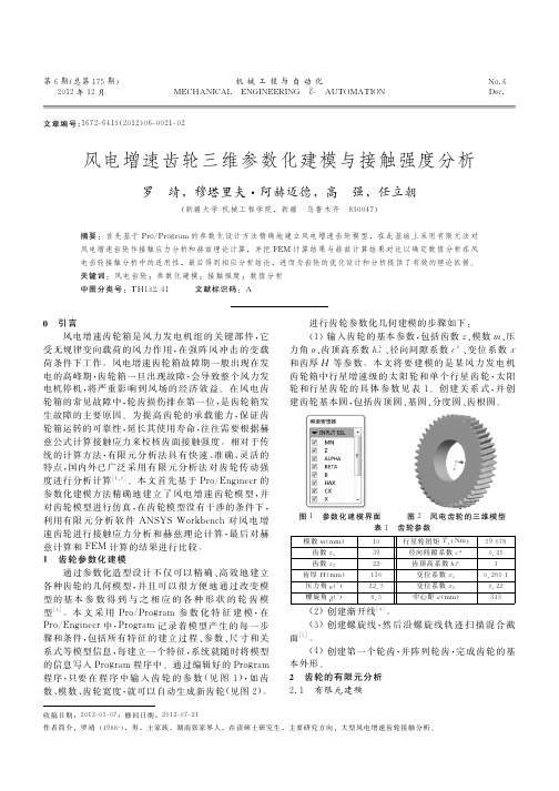
mahony姿态解算算法在机器人技术领域,姿态解算算法(Attitude Estimation Algorithm)是一项非常重要的技术。
随着无人机、自动驾驶车辆和机器人等应用的不断发展,对于准确的姿态解算算法有着更高的需求。
本文将介绍一种被广泛应用的姿态解算算法——Mahony姿态解算算法。
二、算法原理Mahony姿态解算算法是一种基于四元数的滤波算法,在惯导系统中实现姿态解算。
该算法通过运动传感器(如陀螺仪和加速度计)读取数据,并利用基于四元数的滤波器估计出系统的姿态。
具体步骤如下:1. 初始化四元数和其他参数,包括采样周期、姿态误差修正比例系数等。
2. 通过陀螺仪来预测当前时刻的姿态,并将预测的姿态作为初始值。
3. 利用加速度计数据计算出当前时刻的测量姿态。
4. 利用四元数滤波器对预测姿态和测量姿态进行融合,得到最终的姿态解算结果。
三、算法优势Mahony姿态解算算法具有以下优势:1. 精度高:该算法能够以较高的精度估计出系统的姿态,尤其适用于需要高精度姿态解算的应用场景。
2. 实时性好:Mahony算法采用了滤波器的设计,能够实时更新姿态数据,适用于对实时性要求较高的系统。
3. 低计算量:相比其他姿态解算算法(如卡尔曼滤波器),Mahony算法的计算量较低,能够在计算资源受限的设备上高效运行。
四、应用领域Mahony姿态解算算法广泛应用于以下领域:1. 无人机导航:在无人机中,准确的姿态解算算法是实现稳定飞行和导航的关键。
Mahony算法能够提供准确的姿态信息,帮助无人机实现精确的飞行控制。
2. 自动驾驶:在自动驾驶车辆中,准确的姿态解算算法可用于车辆的定位和导航。
Mahony算法可以提供高精度的姿态信息,帮助车辆实时获取准确的位置和方向。
3. 机器人运动控制:Mahony算法在机器人运动控制中也有广泛应用,能够实时估计机器人的姿态,并提供姿态反馈控制,从而实现精确的运动控制。
本文介绍了Mahony姿态解算算法的原理、优势以及应用领域。
海上无人系统跨域协同运用与技术发展邱志明, 孟祥尧, 马 焱, 王 亮, 肖玉杰(海军研究院, 北京, 100442)摘 要: 海上无人系统跨域协同是未来海上无人系统的发展趋势和重要的应用方式。
随着各种海上无人系统的快速发展和在世界局部战争冲突中的应用, 如何更好地使用海上无人系统跨域完成作战任务成为研究的重点。
文中以不同空间域的海上无人系统为研究对象, 梳理总结了当前海上无人系统以及国外海上无人系统跨域运用的发展现状。
重点针对海上无人系统的跨域协同运用基本原理和方法进行了分析, 提出了海上无人系统跨域协同运用的关键问题, 并在此基础上梳理了技术发展中需要重点关注的关键技术。
最后提出了未来发展的几点启示, 以期为海上无人系统的跨域运用和技术发展提供参考和借鉴。
关键词: 海上无人系统; 跨域协同; 技术发展中图分类号: TJ6; U674 文献标识码: R 文章编号: 2096-3920(2024)02-0184-10DOI: 10.11993/j.issn.2096-3920.2024-0053Cross-domain Collaborative Application and Technology Development ofMaritime Unmanned SystemsQIU Zhiming, MENG Xiangyao, MA Yan, WANG Liang, XIAO Yujie(Naval Research Institute, Beijing 100442, China)Abstract: Cross-domain collaboration of maritime unmanned systems is the future development trend and important way of application of maritime unmanned systems. With the rapid development of various maritime unmanned systems and their application in local wars and conflicts in the world, how to better use maritime unmanned systems to complete cross-domain combat missions has become the focus of research. With maritime unmanned systems in different spatial domains as the research objects, the current maritime unmanned systems and the development status of cross-domain application of maritime unmanned systems in other countries were summarized. The basic principles and methods of cross-domain collaborative application of maritime unmanned systems were analyzed, and the key issues of cross-domain collaborative application of maritime unmanned systems were put forward. On this basis, the key technologies requiring attention in the development of technologies were sorted out. Finally, several enlightenments for future development were put forward, so as to provide a reference for the cross-domain application and technology development of maritime unmanned systems.Keywords: maritime unmanned system; cross-domain collaboration; technology development0 引言在新一轮科技革命和世界海军强国竞争的双重驱动下, 无人系统在海战中的地位日益突出。
中法双边化工过程安全学术研讨会时间:2015年6月27日下午14:30地点:虹桥饭店3楼金缘厅一、研讨会流程:(张明广副教授主持)1、介绍与会来宾、领导及同事;2、南京工业大学副校长蒋军成教授致欢迎辞;3、学术报告报告一:Ahmed Mebarki教授报告二:马鹏博士报告二:潘旭海教授4、化工过程安全相关课题研讨(1)中法化工过程风险的差异(2)PRA与QRA方法的比较分析(3)化工过程安全中事故临界状态模拟技术二、参会人员Ahmed Mebarki教授,蒋军成教授、喻源书记、潘旭海副院长、王志荣副院长及安全科学与工程学院全体教师及研究生代表。
AHMED MEBARKI教授是法国UniversityParis-Est Marne-la-Vallée终身教授,目前所在实验室是建模和多尺度仿真实验室。
主要研究方向有自然和工业灾害建模研究,结构脆弱性、结构分析、损伤指数:砌筑、金属、混凝土方面研究,地震、洪水、工业爆炸和结构片段的影响研究,风险与可靠性分析和模拟研究,基于概率的建模研究、多米诺效应优化,灾后评估、损伤识别研究等。
AHMED MEBARKI教授与国际上其他学校科研机构有过多次的合作:2012年作为法方负责人与南京工业大学共同进行了“徐光启中法合作项目”,2011-2014年负责法国与阿尔及利亚的TASSILI CMEP合作项目,2011-2012年作为University Paris-Est Marne-la-Vallée负责人与北京北京城市系统工程研究中心共同完成了“徐光启项目”,2011-2012年作为参与了法国与日本合作的关于海啸危害引发的多米诺效应的研究项目,2001-2007年作为法方负责人完成法国与委内瑞拉的地震风险&结构脆弱性的课题研究。
2008-2011年参与了法国国家项目结构脆弱性动态载荷下的爆炸影响研究。
AHMED MEBARKI教授在国际知名期刊及重要会议上发表70多篇论文,其中被SCI收录论文22篇,多次在英国、土耳其、中国等国际重要会议上作为邀请嘉宾做特邀报告。
【机械】加拿大麦吉尔大学Mahmoud Helmi Attia教授的学术报告圆满结束
研究生之窗讯(通讯员李相欣摄影报道)4月22日上午9点,由加拿大麦吉尔大学机械工程系Mahmoud Helmi Attia教授主讲的“A Unified Approsch to Fretting Wear Prediction Under Sliding/Impact Considering the Effect of Frictional Heating”讲座在摩擦学研究所四楼大会议室顺利举行。
Mahmoud Helmi Attia教授是加拿大麦吉尔大学机械工程系教授、ASME(美国机械工程协会)Journal of Engineering for Industry 的副主编、ASTM(美国试验材料学会)微动疲劳小组的主席。
2003年获得美国机械工程协会机械制造工程方向的最佳论文奖;结构节点的非线性热弹性理论获得ASME颁发的布来科尔机器工具与器具奖。
研究主要基于物理模型建模来考察其热弹性及动力学行为,实现加工制造及摩擦系统优化设计与控制、高速/高性能加工。
讲座伊始,Mahmoud Helmi Attia教授给在座的同学和老师讲了摩擦引起的温升和热应力的微动。
Mahmoud Helmi Attia教授讲到这项工作为微动摩擦和疲劳测试的模拟和标准化提供了工具,并在摩擦焊接过程中得到最优。
随后还讲到了预测微动疲劳强度和结构部件的剩余寿命,考虑了材料的非线性,并用摩擦热有关的热收缩现象和热应力断裂力学进行分析说明。
随着演讲的进行,老师和同学们都听的很仔细,并且记录了自己的疑问。
在讲座的最后一个环节,有很多博士生提出自己的疑问,包括在讲座过程中不理解的专业问题。
Mahmoud Helmi Attia教授都给一一解答了,教授和同学们有了很好的互动。
演讲结束后,很多同学还在探讨所听到的内容。
在一片讨论声,这次的学术讲座圆满结束。