碧河太阳能热水自动控制系统BF-160MW说明书
- 格式:pdf
- 大小:3.38 MB
- 文档页数:6

太阳能热水器微电脑全智能测控仪使用说明 Document serial number【UU89WT-UU98YT-UU8CB-UUUT-UUT108】太阳能热水器微电脑全智能测控仪使用说明现在目前大多数太阳能微电脑的功能与操作如下:(说明:为了用户跟好使用,本人义务为大家扫描微电脑说明书,有可能个别字乱码错误,见谅)特点:上水实现全自动,有恒温补水功能,定时上水,水温水位数码彩屏显示,采用人性化设计,具有水位预置、低水压上水模式、可定时控制,手动控制、自动防溢流、高温保护等主要功能,使用更方便、更安全、更实用。
一、主要技术指标1、使用电源:220VAC功耗:<5W2、测温精度:±2℃3、测温范围:0-99%℃4、水位分档:五档5、电磁阀参数:直流DCl 2V,可选用有压阀或无压阀二、主要功能1、开机自检:开机时发出“嘀”提示音,表示机器处于正常状态2、水位预置:可预置加水水位50、80、100%3、水位显示:显示太阳能热水器内部所有水量4、水温显示:可显示太阳能热水器内部实际水温5、水温预置:可预置加热温度30%-80%,若不需要加热功能,可预置为00℃。
6、缺水报警:当水位从高变低,出现缺水状态时,蜂呜报警,同时位时,测控仪会自动进入低水压模式,“低水压”图案点亮,在此上水模式中,测控仪会间隔30分钟启动一次,同时测控仪自动静音,以免上水、关闭时经常蜂呜,打扰用户休息:按“上水键”可取消该次低水压上水模式:11、温控上水:当水箱水未加满,水温以超过85~C时,自动补水至合适水温65cC左右,此功能可防止出现低水量高水温的不合理现象。
12、定时上水:若有供水不正常,有时有水,有时没水等特殊情况用户可根据自己的生活习惯,设定定时上水或定时加热,设定完毕后测控仪每天会根据所设定的时间自动上水及加热。
1 3、强制上水:水位传感器出现故障时,可按“上水”键,实现强制止水,每分钟会出现蜂鸣提示,注意有无溢水,8分钟后自动关闭上水。
Instruction ManualDESCRIPTIONThe Aquasun 2 is an entry level automatic solar controller with temperature adjustment, manual mode and winter mode features. Mode of operation and the temperature limit setting are retained after a power outage.INSTALLATION INSTRUCTIONSCONTROLLER INSTALLATIONFind a suitable location to mount the control box. The controller should be installed out of direct weather and no closer than 3 meters from the water’s edge. Lift up the two mounting tabs and use two appropriate screws to mount the control box to the wall, keeping in mind that the power cable is 1.8m long and should be plugged directly into a general power outlet, not into an extension lead.The solar pump plugs into the 240Vac socket marked as PUMP.The pool sensor must be fitted into the suction line of the pump, as close to the pool as practical, preferably in a position out of direct sunlight. It is recommended that a 14.5mm hole be drilled in the PVC pipe, this can be carried out using a Dontek PD01 grinding drill or a small pilot hole can be drilled and a 14.0mm drill-bit used spinning in a counter clockwise direction to minimize the chance of shattering pipe. Insert the grommet into the pipe and gently push in the blue/grey sensor barb. The blue sensor plug is to be fitted to the plug socket marked POOL. DO NOT cable-tie or tape sensor wires to mains power, In some cases there is some benefit to cable tie 30cm of wire from the sensor to the pipe and insulate this section (some ambient differences can travel up the copper wire and affect the sensor reading). Roof sensors must be fitted into a small piece of solar collector or equivalent and attached to the roof. The best location is within an arm's length of the gutters edge of the house or shed as long as the sensor end is not shaded and is on a roof of similar aspect of the main collector. It must not be fitted on top of the solar collector or fitted to high points on the roof like Ridge Capping as false readings will be detected. Keep in mind that it is of the utmost importance to keep the roof sensor as short as possible as this will assist in the longevity of the sensor and controller in the event of electrical storm activity and power surges. Sensor cables must not be run parallel to power cables and run lengths should be less than 50m. Cable ties should be used to fasten the sensor cable to the cold water inlet pipe making sure that the ties are approximately 10mm from PVC fittings. Cable ties should be tightened only firm, over tightening can cause breaks in the outer PVC if not careful. If the cable is to be run under ground a conduit must be used to protect the wire and there is to be no cable joins within, conduit ends must be sealed to prevent water ingress.Any excess cable should be removed and re-fitted ensuring that the wire ends are tinned with solder. The red sensor plug is to be fitted to the right hand socket marked ROOF.CONTROLLER OPERATION AND SETTINGS TEMPERATURE LIMITTo change the temperature limit that determines when to start or stop the pump simply press (or hold) the UP button to increase the desired temperature limit, the DOWN button will decrease it.If the temperature limit is set below the current pipe temperature then the pump is automatically started for 3 minutes to test the true pool water temperature.The controller will automatically choose to run the pump based on solar gain (i.e. the sun is shining & roof is hot) Once the desired temperature is achieved the pump is stopped and a four hour wait commences to ensure no energy is wasted by unnecessarily starting the pump. If after 4 hours the roof is hot enough then the pump may start to provide a 2nd heating cycle, if not then the “waiting for roof to warm” message will appear. If the poolachieves temperature limit during the 2nd heat cycle then it will start an economy/sleep mode, which will prevent the pump from starting for the rest of the day.MANUAL PUMP MODEHolding the UP button to go above 40°C will toggle the pump from Off to On or vice versa, Manual mode will time out after 30 minutes of being selected, with a default temperature limit of 30°CWINTER MODEHolding the DOWN button to go below 20°C will set the unit into WINTER mode, on selection of winter mode the pump will run for 3 minutes and will repeat this every day at the same time unless the power fails. Should there be an interruption to power then an exception takes place to prevent the pump starting at night, the sensors are tested to check that the roof sensor is 5°C or more above the pipe sensor, if this temperature condition is not met the display will show “waiting for roof to warm”, once the pump starts the controller will wait 24 hours to perform another unconditional flush of the system.SUMMER MODESummer mode is the default mode of operation; if tropical mode has been selected you can change back to summer mode push both buttons and when SUMMER is displayed, released the buttons and use the up or down buttons to set the desired temperature. The controller will automatically heat the pool to this temperature when solar conditions are favourable.TROPICAL MODETo activate tropical mode, push and hold both buttons and when “TROPICAL” is displayed, release the buttons and use the up or down button to set the desired temperature. In tropical mode the controller will attempt to heat the pool, if the pool exceeds the temperature limit while heating then the controller turns off the pump and waits for the roof to cool so the controller can cool the pool down by dissipating the heat on the cold roof (most likely to occur at night). In tropical mode the controller attempts to keep the pool at the temperature limit by either heating or cooling as required.NOTES1.If a sensor fault is detected the controllerwill display which sensor failed (POOL and/or ROOF) and the type of failure.2.After a power outage all configurableitems are retained & the clock (if used) will keep time for up to 14 days.3.The sensor cable with the red trace is thepositive and is usually fitted to the right hand side of the plug when looking at the plug screws, incorrect polarity may be displayed as a short circuit fault.4.If the controller has stopped pumping andis displaying a higher temperature than expected it may be caused by a pump which is failing to prime, check the pump and if necessary prime the pump as per the pump manufacturers’ instructions then reset the controller by turning it off/on.5.Maximum rated output load for the 240Vsocket is 9.98 Amps / 2395 Watts.6.Degree of protection against moisture:IP23WARRANTY – AQUASUN 2This range of product is covered by a limited 2 year warranty against component failure or faulty workmanship from the date of installation.A faulty unit should be returned in the first instance to the dealer from which the unit was purchased.Damage to the unit due to misuse, power surges, lightning strikes or installation that is not in accordance with the manufacturer’s instruction may void the warranty.Warranty does not include on-site labour or travel costs to or from installation site.If the power cord is damaged, do not use the controller; return the unit to the supplier for repair. CUSTOMER RECORD (To be retained by the customer)DEALER/INSTALLER NAMESERIAL NUMBERDATE INSTALLEDFor service assistance phone 1300 130 693.auDontek Electronics Pty LtdPO Box 239, Bayswater VIC 3153 AustraliaPhone:+61397628800Email:****************.au。
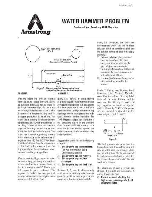
With the steam line pressure running from 125 lbs. to 150 lbs. there will always be sufficient differential for the traps to discharge to the return line. But this is not an ordinary condensate return line -- with the condensate temperature fairly close to the steam pressure in the return line. The return line is handling the discharge from condensate pumps which are assumed to be taking condensate from low pressure traps and boosting the pressure so that it will flow back to the boiler room. The return line, is therefore, probably running full of condensate at the temperature of anywhere from 180˚F to 210˚F. Very likely it will be a lot lower than the temperature of the flash and condensate from the drip trap. Under these conditions water hammer could be quite a problem.What do you think? If you agree that water hammer is likely, what do you suggest as an alterative hookup to the one shown in the accompanying sketch? Please give full reasons for your conclusions. The engineer that offers the best practical solution will receive an award post haste to compensate for their effort.PROBLEMANSWERSNinety-three percent of those replying said there would be water hammer. In fact, several engineers proved with calculations that flash steam would form in sufficient quantities when the high temperature trap discharge met the lower pressure to make water hammer almost inevitable. The TRAP Magazine judges agreed that under the conditions stated in the problem, water hammer would very probably occur, even though some readers reported that under somewhat similar conditions they had no problem.Suggested solutions fell into the following categories:Solutions 2, 3, and 4, while perfectly valid means of avoiding water hammer, generally would be more expensive and complicated than the situation calls for.1) Discharge the trap to atmosphere. This was eliminated as being unnecessarily wasteful.2) Discharge the trap to a receiver.3) Discharge the trap to a heat exchanger.4) Discharge the trap to a flash tank.Again, it’s recognized that there are circumstances where any one of these solutions could be considered ideal, but the solution named as best must apply generally.Reader T. Mackie, Head Plumber, Royal Alexandra Hotel, Winnipeg, Manitoba, exemplifies this school: “It is my belief there will be water hammer and to overcome this difficulty it would be my suggestion to install an ‘ejector’ such as Penberthy XL96” of the proper size and installed as illustrated in the accompanying sketch (Figure 2).“The high pressure discharge from the trap while passing through the ejector will pick up water from low pressure return and so will reduce the temperature of the high pressure discharge to nearer the low pressure temperature and in this way avoid water hammer.”The advantages of such a system are obvious. It is simple and inexpensive. It works. It wastes no heat.5) External radiation. These included long drip legs ahead of the trap, long return lines from the trap, fin type radiation, tempering coils,etc. Such systems did not get the nod because of the needless expense, as well as the waste of heat.6) Ejectors. Solutions employing ejector ran a very close second to the winner.7) Special means of admitting the high pressure discharge into the 50 psi return header.WATER HAMMER PROBLEMCondensed from Armstrong TRAP MagazineBulletin No. 206-CFigure 2.Figure 1. Shows a proposed drip connection for an overhead outdoor steam distribution system.This category contained the winner. W.F. Gundlack, C.E., Twin Cities Arsenal, Federal Cartridge Corporation, New Brighton, MN, came up with a hookup remarkable in its simplicity. Figure 3 demonstrates this. In the opinion of the TRAP Magazine judges, admitting the flash steam in the direction of the flow of the condensate in the manner shown will be sufficient to prevent water hammer. Mr. Gudlack also offered the installation of tempering coils (Figure 4) in conjunction with the curved nipple as an even surer cure for water hammer, but this should not be necessary in most cases. The award therefore goes to W.F. Gundlack on the basis of providing the simplest, most practical and proven solution.THE WINNERJ.M. Parish, Mechanical Engineer, Dow Chemical Company, Freeport, TX was close to the winning solution when he stated “...inject the trap discharge into the condensate line though a properly designed nozzle,” but did not include enough detail.NEAR MISSESA similar solution employing the same method of admitting the flash steam but using perforated piping (Figure 5) was advanced by readers, P .F. Krol, Cranford, NJ and J.M. Perish, Freeport, TX. In this system, flash steam is admitted more gradually and over a greater area, though still at right angles to the condensate flow, which may cause some turbulence.Figure 3.Figure 4.Figure 5.Figure 6.TIPS ON IMPROVING PIPING PRACTICESWith the water hammer problem out of the way, several engineers went on to improve the general piping from that which was originally shown, particularly in consideration of the fact that this is an outdoor installation and freezing is a definite consideration.The TRAP Magazine presented an unmodified customer’s drawing and was criticized about some omissions. Figure 6 therefore rights this situation by revising the original to conform with the “American Standard Code for Pressure Piping”.1) Drip pocket.2) Shut off valve as close as possible to steam main and at high point on outdoor installation.3) For free blow to atmosphere also getting sediment out of dirt pockets.4) Permit shut off for trap inspection or removal; necessary if bypass is used, otherwise convenient.5) Strainer -- not necessary on larger Armstrong inverted bucket traps.6) Test valve -- optional.7) When valve (3) is opened for manual blowdown, there will be a pressure drop in the line to the trap which may cause trap prime to flash and make the trap lose its seal. Such traps should be protected by installing an Armstrong InternalCheck Valve, (7) or by a swing check valve between the trap and valve.8) Pop Drain protects trap against freezing, automatically drains trap when the steam pressure is below 8-9 psi. Check valve (7) should not be used with pop drain, althoughstrainer (5) with blow down valve is essential. Check valve (9) may also be omitted.9) This check valve prevents backflow into the trap.10) Permit shutoff for trap inspection or removal; necessary if bypass is used, otherwise convenient.11) Bypass valve12) Shutoff valve as close as possible to return header and at high point on outdoor installation.One reader questioned the use of a bypass on an outdoor installation. Many would subscribe to omitting the bypass particularly when using Armstrong traps which seldom need attention. If a bypass is used, provision for draining it to prevent freezing is recommended.Armstrong InternationalPhone: (269) 273-1415 • armstrong Bulletin No. 206-C 5/10 Printed in U.S.A.。

说明书一、产品介绍:太阳能集热工程控制柜是为集中供热水的太阳能工程及别墅型太阳能热水器专门开发研究的智能测可靠性和使用寿命的问题,且结构简单、使用方便、稳定性好、不受水箱温度及水质的影响、水位检测可从十几厘米到几米,性价比极高,是目前水箱水位检测最理想的装置之一;温度传感器采用优质高价进口材料,可根据用户要求,检测度可达200℃(一般的只能到120℃),完全满足了工程型集热器的工作要求;主要电子元器件全部采用美国原装进口器件,双电源供电,光电隔离设计,工作稳定可靠,不受强电工作干扰;系统采用三相电(交流380V)和单相电(交流220V)兼容的方式,大功率设计,以适应用户不同的工作环境及更高的配件可选性和系统工作效率,电加热棒采用交流380V或交流220V 自选,最大可控功率可由用户制定,增压泵及循环泵最大可控功率均为1500W,并可根据用户要求增加其可控功率;多指示灯指示;当系统出现问题时可开启手动;当前工作状态直观明了;充分考虑安全性,装配高质量漏电保护系统。
同时为了适应不同的用户要求,公司根据各种系统要求,开发了大型软件系统,最大限度地方便了用户需求和现场安装调试,所有功能可现场随机取舍,所有参数可根据现场硬件情况及用户要求随时设置,并且可根据用户的要求,以最低成本升级系统功能,以满足用户的不断发展要求。
二、技术参数:1、主机消耗功率:<5W (不含电加热、水泵、电磁阀);2、工作电压:AC220V/380V ±10% 50Hz;3、电磁阀参数:AC220;4、测温精度:±2℃;5、测温范围:0~99℃;6、水位分档:五档;7、控制电加热功率:(根据客户要求来订)8、热交换泵功率一般:≤ 1500W (≤1500W 根据客户要求来订)9、管道循环泵功率一般:≤1500W(≤1500W 根据客户要求来订)10、漏电动作电流≤30mA/0.1S(大电流配件正泰电器二、功能介绍:显示部分:1、超大LED集成显示:集热器温度、保温温度、管道温度、保温水位、恒温水箱温度、恒温水箱水位、低温温度、显示北京时间及工作状态,系统运行时一目了然;2、自动上水(水位控制、定时控制)功能;当水箱水位降至进水位时,控制器会自动上水,加水至设定的上限水位自动停水。
个人资料整理仅限学习使用太阳能热水器控制系统的设计摘要本设计以单片机AT89S52 为中心,联合了单线数字温度传感器DS18B20 与液晶显示器 1602,设计出一种数字化、智能化的太阳能热水器控制系统。
该系统由主控芯片模块、 DS18B20 温度检测模块、 LCD 显示模块、水位检测模块、报警模块和电磁阀控制模块构成。
剖析了各个模块的构造及其工作原理、绘制了系统硬件原理图、程序流程图,并编写源程序,进行电路板的调试和实验考证。
此系统排除了热水器上水时需人工等候和过度溢水的问题,达到了省时、环保、节水的目的。
该系统与传统的机械式控制系统对比较,拥有构造简单,抗扰乱能力强,使用方便等特色。
重点词:太阳能热水器, AT89S52, DS18B20Solar Water Heater Control SystemAbstractThis design utilizes MCU AT89C52 as the core,and combines wire digital temperature sensor DS18B20 and LCD display 1602,to design a solar water heater control system that was digital and Intelligent.This system consists of many modules ,which include Master chip module,DS18B20 temperature detection module ,LCD display module ,Water level detection module ,Alarm module ,Solenoid valve control module .This paper will analysis of the structure of each module and its working principle ,draw the System hardware schematic and program flow chart, write source code, debug circuit boards,as well as Experiments.The system has settledthe dispute that people is needed and overflow when feeding water to heater,and achieve the purpose of saving time and water and protectingpared with traditional mechanical control systems,this system has several advantages,such as simple construction, Anti-interference ability,convenient to use and so on.Keywords:solar water heater,AT89C52,DS18B20个人资料整理仅限学习使用目录1前言1.1 研究的目的和意义跟着社会的高速发展,能源问题已成为目前全球面对的最为突出的问题之一,而太阳能是人类取之不尽、用之不停的洁净能源。
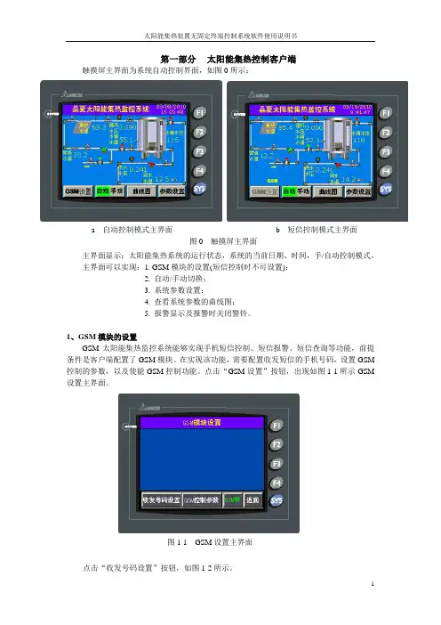
第一部分 太阳能集热控制客户端触摸屏主界面为系统自动控制界面,如图0所示:主界面显示:太阳能集热系统的运行状态,系统的当前日期、时间,手/自动控制模式。
主界面可以实现:1. GSM 模块的设置(短信控制时不可设置);2. 自动/手动切换;3. 系统参数设置;4. 查看系统参数的曲线图;5. 报警显示及报警时关闭警铃。
1、GSM 模块的设置GSM 太阳能集热监控系统能够实现手机短信控制、短信报警、短信查询等功能,前提条件是客户端配置了GSM 模块。
在实现该功能,需要配置收发短信的手机号码,设置GSM 控制的参数,以及使能GSM 控制功能。
点击“GSM 设置”按钮,出现如图1-1所示GSM 设置主界面。
点击“收发号码设置”按钮,如图1-2所示。
图1-1 GSM 设置主界面 a 自动控制模式主界面 b 短信控制模式主界面图0 触摸屏主界面其中,接收手机号码为本系统手机号码白名单,即,本系统只接受该设置的接收手机号码;发送手机号码为接收本机发送报警短信、系统参数等短信的手机号码。
设置时,点击对应号码的文本框,此时该文本框出现高亮,点击窗口下面的数字进行手机号码的输入、编辑。
本系统设计收发号码均为两个。
点击右上角“确定”窗口,系统控制器根据设置的手机号码进行设置。
此时,出现如图1-3所示界面,等待约10s左右,系统提示配置是否成功标志,如图1-4所示。
该系统提供给用户是否选用GSM功能,可以点击“GSM开/关”按钮,实现GSM功能的开/关。
2、自动、手动切换系统主界面为自动控制界面,当选择手动控制模式,可以点击“自动/手动”按钮实现,输入对应正确的密码,进入手动控制界面。
当“自动控制”切换到“手动控制”模式时,执行机构全关断,如图2-1所示。
手动控制界面中,可以选择不同手动控制功能,同时显示执行机构的工作状态及系统参数。
当点击“返回”按钮,即由“手动控制”切换到“自动控制”模式。
同时按自动控制图1-3 收发号码设置等待图1-4 模块设置失败显示图1-2 收发号码设置界面策略运行。
某太阳能热水器工程说明和使用说明书欢迎使用某品牌系列太阳能热水器,为了使该产品更好地为您服务,请在使用前阅读本说明书,祝您的生活充满阳光,日日温馨!一、工程概况本工程为某单位新建厂区内生活区 --员工宿舍楼太阳能热水项目,工程范围包括:首层设备房内的冷水管、热水管、回水管及其保温、太阳能电气系统;屋顶太阳能集热器及支架、基础,热媒循环管道及保温,设备房内设备、锅炉排烟管等。
系统共计安装太阳能集热器712m2,以解决912人采用花洒方式使用热水冲凉,太阳能集热系统不足的热量由燃气热水锅炉提供。
集热板采用平板型太阳能集热器,单层布置,集热器及热媒管内一栋充注防冻液 28.4%的乙二醇作传热介质。
另一栋充注防冻液 65%的 1.2丙二醇作传热介质,系统循环管采用串并联结合,同程强制循环的方式连接。
室内冷水、热水配水管网已由甲方施工完毕,并在首层设备房内预留与太阳能系统的接口,不包含在本项目内。
二、产品结构本系统主要由:高效平板型集热器、不锈钢保温水箱(包括储热水箱和半容积式加热水箱)、上下循环管和支架、燃气锅炉、强制循环装置、自动补冷水装置、自动供热水装置、自动回水装置等。
三、性能特点1、安全性:某单位太阳能热水器是利用太阳辐射把水加热的一种光热转换装置,无中毒、触电等危险。
2、可靠性:由于某单位太阳能热水器主要材料采用进口或国产的优质产品,并且在生产、安装过程中严格遵循公司的质量保证体系,因此产品质量有充分的保证。
3、舒适性:利用高新技术制造而成的控制系统,必须专人操作,并有多项故障自检功能,方便用户的检查和维护,使用时只需打开卫生器具即可使用热水。
4、先进性:某单位太阳能热水器采用了公司多项专利技术,大大提高了热效率,节约了能源,减少环境污染。
5、经济性:一次投资安装后,无须再增加更多的补充能源投资,它的使用寿命长达15年之久,一般投资回收期为 2-3 年,具有“一次投资,长期受益”的特点,由于采用了高效集热器和性能可靠的控制系统,投高了热效率,降低了运行和维修费用,主体工程安装于楼面,无须占用室内空间,并且有良好的隔热效果,可省去安装隔热层费用,停(缺)水时,太阳能储水箱更是一个理想的储水箱。
太阳能热水器微电脑全智能测控仪使用说明现在目前大多数太阳能微电脑的功能与操作如下:(说明:为了用户跟好使用,本人义务为大家扫描微电脑说明书,有可能个别字乱码错误,见谅)特点:上水实现全自动,有恒温补水功能,定时上水,水温水位数码彩屏显示,采用人性化设计,具有水位预置、低水压上水模式、可定时控制,手动控制、自动防溢流、高温保护等主要功能,使用更方便、更安全、更实用。
一、主要技术指标1、使用电源:220VAC功耗:<5W2、测温精度:±2℃3、测温范围:0-99%℃4、水位分档:五档5、电磁阀参数:直流DCl 2V,可选用有压阀或无压阀二、主要功能1、开机自检:开机时发出“嘀”提示音,表示机器处于正常状态2、水位预置:可预置加水水位50、80、100%3、水位显示:显示太阳能热水器内部所有水量4、水温显示:可显示太阳能热水器内部实际水温5、水温预置:可预置加热温度30%-80%,若不需要加热功能,可预置为00℃。
6、缺水报警:当水位从高变低,出现缺水状态时,蜂呜报警,同时位时,测控仪会自动进入低水压模式,“低水压”图案点亮,在此上水模式中,测控仪会间隔30分钟启动一次,同时测控仪自动静音,以免上水、关闭时经常蜂呜,打扰用户休息:按“上水键”可取消该次低水压上水模式: 11、温控上水:当水箱水未加满,水温以超过85~C时,自动补水至合适水温65cC左右,此功能可防止出现低水量高水温的不合理现象。
12、定时上水:若有供水不正常,有时有水,有时没水等特殊情况用户可根据自己的生活习惯,设定定时上水或定时加热,设定完毕后测控仪每天会根据所设定的时间自动上水及加热。
1 3、强制上水:水位传感器出现故障时,可按“上水”键,实现强制止水,每分钟会出现蜂鸣提示,注意有无溢水,8分钟后自动关闭上水。
三、使用方法通电后,测控仪会自动将水位加满至100%,如果无太阳光照使水温升高,则3小时后自动加热至水温50℃,太阳能上水、加热是合智能运行的,因此,用户不必作任何操作,若想变更预置水位、水温或采用定时模式,可按如下方法操作:1、水温水位设置:先按“预置”键,当前预置温度。
太阳能热水器控制仪使用说明书第一篇:太阳能热水器控制仪使用说明书太阳能热水器控制仪使用说明书太阳能热水器使用说明,一般情况下也就是说的太阳能热水器控制仪的使用方法,在这里我们拿最常用的西子控制仪说明书,为大家讲解一下使用方法,希望对大家在使用过程中减少一些疑难问题,方便大家使用。
TMC至尊全天候测控仪使用说明书【主要技术指标】1.使用电源:220VAC功耗:<5W2.测温精度:±2℃3.测温范围:0-99℃4.控温精度:±2℃5.水位分档:五档环形显示6.可控水泵或电热带功率:≤500W7.可控电加热功率:≤1500W可选:3000W8.漏电动作电流:≤10mA/0.1s9.电磁阀参数:直流DC12V,可选用有压阀或无压阀有压阀工作压力:0.02MPa~0.8MPa无压阀工作压力:0.0MPa,适用于水箱供水或低压供水10.广域亮彩显示屏低功耗:<0.5W【主要功能】1.北京时间:实时显示北京时间2.水位预置:可预置加水水位50、80、100%3.水温预置:可预置加热温度范围:30℃-80℃,定时加热若不需要启动电加热,可预置为00℃4.水温指示:显示太阳能热水器内部实际水温5.水位指示:显示太阳能热水器内部所存水量6.缺水提示:当水位从高变低,出现缺水状态时,蜂鸣报警,同时20%水位闪烁7.缺水上水:当水位从高变低,出现缺水状态时,延时30分钟自动上水至预置水位8.手动控制:可手动启动上水、加热,在操作时首先显示预置的水位或水温,用户可利用▲、▼键调整预置参数,确认后,启动上水、加热,也可手动关闭。
启动加热时水位若低于50%,则先启动上水再加热。
正在加热时水位低于50%自动关闭加热,保护电加热管。
启动手动上水时,若实际水位大于等于预置水位时,测控仪自动上调预置水位,以保证用户上水需求,启动手动加热时,若实际水温大于等于预置水温时,自动上调预置水温,以保证用户加热需求,建议用户预置水温不超过60℃9.自选模式:有智能、定时、温控三种模式可选定时模式:可设定二次定时上水、二次定时加热,原厂设置定时上水第一次9:00上水至100%水位,第二次15:00启动上水至100%水位。

太阳能热水系统智能控制器安装使用说明书HB1105012年月日太阳能热水系统智能控制器安装使用说明书非常感谢您选用CA3型工程控制器,该款工程控制器主要用于联集管式太阳能热水工程。
请您在安装系统前详细阅读本说明书。
目录一、安全指导及安全规则 -------------------------------------------------------------------------------------- 3二、主要技术指标------------------------------------------------------------------------------------------------ 3三、控制系统安装------------------------------------------------------------------------------------------------ 4四、主要功能 ------------------------------------------------------------------------------------------------------ 5五、用户操作界面------------------------------------------------------------------------------------------------ 7六、故障显示及处理-------------------------------------------------------------------------------------------- 12七、水位传感器安装及高水位设定------------------------------------------------------------------------- 12一、安全指导及安全规则在安装及使用设备前,请详细阅读以下所列的安全规则和警告。
昆山绿材机电热水系统使用说明书昆山绿材机电工程有限公司江苏省昆山市淀山湖镇新华路16号敬告用户感谢您选购本公司太阳能热水系统,为使您能够正确使用本系统,并得到满意效果,请您务必在使用之前,详细阅读本说明书。
目录系统设计依据 (3)系统设计特点和参数 (4)操作说明 (6)常见故障分析与处理 (13)保养与维护 (13)电路图……………………………………………………...附件注意:安装和维修必须由持有有效证件的专业人员来操作系统设计依据1. GB/T6424-2002《太阳能集热技术条件》2. GBJ15-88《建筑给水排水设计规范》3. GB/T17581-1998《太阳能集热器》4. 本方案用户对使用热的一般要求系统设计特点和参数1. 设计特点:1.1本系统采用巨仲电子开发之高效平板式太阳能集热器作为前级加热装置,在晴好天候条件下充分利用太阳能;1.2本系统采用空气源热泵作为中级加热装置,在环境温度为零度以上时充分利用空气中所含的热能;1.3 本系统采用电加热作为后级加热装置,以确保在任何天候情况下稳定的热水供应;1.4 系统温控装置可确保在任何天候条件下,产水温度可达摄氏55度甚至以上;1.5 系统具备抗风能力,且符合环保及消防要求;1.6 系统安装时不损坏楼面,运行中不超过楼层承载能力。
2. 主要设备参数:2.1 平板式太阳能集热器:集热器性能参数尺寸 mm1350×900×70板面面积㎡ 1.17有效采光面积㎡1日平均效率 %≥55最高瞬时效率 %≥85热损系数W/㎡K≤4.0工作压强 MPa≤1.1耐压 Mpa≤1.8工作温度℃-5~100重量 kg25主要材料、材质板芯类型全紫铜板芯吸热模层高吸收涂层膜层吸收率≥90%±2%膜层发射率≤15%±2%主管材料Al6063-T5支管材料尺寸T2铜管Φ16×0.5mm玻璃盖板材料及厚度浮法平板玻璃,4.0mm盖板板面尺寸1345×895mm盖板透光率≥80%保温材料抗老化保利龙板保温层厚度20/35背板材料及厚度0.3mm镀锌板密封结构金属弹性密封+橡胶条密封圈材料三元乙丙橡胶2.2注:以上数据测试条件为室外环境温度20度,进水温度15度,出水温度55度;环境温度越低,热泵的制热效率 (以COP衡量) 会越差。
太阳能热水工程(热水器)是产生热水的换热设备。
水是真空管的换热介质,真空管给水的水质好坏,对于太阳能的安全运行、能源消耗和使用寿命有至关重要的影响。
集热效率是太阳能热水器品质的重要指标之一,按推荐性国家标准GB/T17049-2005《全玻璃真空太阳能集热管》规定,全玻璃真空管的太阳能吸收比应不小于0.86,相信能达到这一指标的太阳能热水器占90%以上,但这只是指新的在未使用的状态下,而在实际使用中,因水中的水垢很快(最多一两个月)在真空管的内壁形成一个垢膜(用过热水瓶的人都有这个体验),使阳光对真空管的穿透率大幅下降,所以一般太阳能热水器在使用半年以后,其太阳能吸收比会下降至0.5以下。
所以不论什么样吸收比的太阳能真空集热管,使用半年后其吸收比这样一个关键性的指标最后都差不多。
这个问题在行业二十年中为大多数人所知道,却又不愿意提及的一件事。
很像三聚氰胺在食品行业中作为添加剂,可以提高蛋白质的检测指标(含氮量增高了),但实际上蛋白质含量并未增加;真空管新的时候吸收比高,但是实际使用后(太阳能热水器是买来用的,不是买来看的)其吸收比如何却无人问津。
在水垢严重的地区,甚至会发生管道堵塞的现象。
从上可知,水质不良的危害是十分严重的,在不重视太阳能水处理工作的单位,其太阳能运行状况往往是:半年好,一年赖,有上贰年就全坏。
:这不仅会带来巨大的经济损失,而且还会产生停产和炸管,漏水等重大安全责任事故。
但是,水质不良的危害往往是一个积累过程,需经过一定的时间才能发现,可是上述危害一旦发现,那就已经形成了难以挽回的局面和损失,因此,安装太阳能水处理设备(硅磷晶)是十分必要的,即保证了锅炉的正常运行和延长寿命,又节约了能耗!热水器作为一种节省能源,保护环境,方便群众的产品越来越广泛地进入社会,进入家庭。
“许多用户不但用太阳能热水洗脸、洗澡、洗碗、洗衣服、洗菜、淘米,有的甚至用来煮饭、煮菜,烧开水等,这样做对吗?”对此王昕主任谈到:“这是关系到广大用户的健康问题。
太阳能热水器微电脑全智能测控仪使用说明令狐文艳现在目前大多数太阳能微电脑的功能与操作如下:(说明:为了用户跟好使用,本人义务为大家扫描微电脑说明书,有可能个别字乱码错误,见谅)特点:上水实现全自动,有恒温补水功能,定时上水,水温水位数码彩屏显示,采用人性化设计,具有水位预置、低水压上水模式、可定时控制,手动控制、自动防溢流、高温保护等主要功能,使用更方便、更安全、更实用。
一、主要技术指标1、使用电源:220VAC功耗:<5W2、测温精度:±2℃3、测温范围:0-99%℃4、水位分档:五档5、电磁阀参数:直流DCl 2V,可选用有压阀或无压阀二、主要功能1、开机自检:开机时发出“嘀”提示音,表示机器处于正常状态2、水位预置:可预置加水水位50、80、100%3、水位显示:显示太阳能热水器内部所有水量4、水温显示:可显示太阳能热水器内部实际水温5、水温预置:可预置加热温度30%-80%,若不需要加热功能,可预置为00℃。
6、缺水报警:当水位从高变低,出现缺水状态时,蜂呜报警,同时位时,测控仪会自动进入低水压模式,“低水压”图案点亮,在此上水模式中,测控仪会间隔30分钟启动一次,同时测控仪自动静音,以免上水、关闭时经常蜂呜,打扰用户休息:按“上水键”可取消该次低水压上水模式:11、温控上水:当水箱水未加满,水温以超过85~C 时,自动补水至合适水温65cC左右,此功能可防止出现低水量高水温的不合理现象。
12、定时上水:若有供水不正常,有时有水,有时没水等特殊情况用户可根据自己的生活习惯,设定定时上水或定时加热,设定完毕后测控仪每天会根据所设定的时间自动上水及加热。
1 3、强制上水:水位传感器出现故障时,可按“上水”键,实现强制止水,每分钟会出现蜂鸣提示,注意有无溢水,8分钟后自动关闭上水。
三、使用方法通电后,测控仪会自动将水位加满至100%,如果无太阳光照使水温升高,则3小时后自动加热至水温50℃,太阳能上水、加热是合智能运行的,因此,用户不必作任何操作,若想变更预置水位、水温或采用定时模式,可按如下方法操作:1、水温水位设置:先按“预置”键,当前预置温度。
F 系列分离式太阳能热水系统使用说明书(确保系统的安全运行,使用前请仔细阅读本说明书) 北京创意博能源科技有限公司 Beijing CIB Solar ltd尊敬的用户: 感谢您选择使用 CIB 分离式太阳能热水系统(以下简称热水系统)!为了方便您更好的使用,使用前请仔细阅读本说明书,正确掌握本说明书中的 安装步骤和使用方法,以充分利用本系统的优异性能。
请妥善保管本说明书。
本说明书只涉及热水系统的使用说明。
热水系统必须由我们公司指定的 专业安装人员经行安装。
您在使用过程中出现问题,请与当地的经销商联系,我们将及时为您解 决。
本公司有权对产品进行修改和改进,不负有对已出厂产品经行相应修改 和改进的义务,特此声明。
产品执行标准 GB/T 17581 – 2006 真空管型太阳能集热器技术条件 GB/T 19141 – 2003 家用太阳能热水系统技术条件 GB – 2006 家用和类似用途电器的安全贮水式电热水 器的特殊要求 GB 家用和类似用途电器的安全第 1 部分通用要求 GB/ 家用和类似用途电自动控制器通用要求 GB/T 家用和类似用途电自动控制器家用电器用电控制器的特殊要求目录一、产品介绍----------------------------------------------------4 二、主要技术指标及型号说明-------------------------------4 三、系统安装及调试-------------------------------------------5 四、控制功能简述----------------------------------------------6 五、用户操作说明----------------------------------------------8 六、故障显示及处理-------------------------------------------10 七、附图----------------------------------------------------------11 八、售后服务---------------------------------------------------13一、产品介绍➢ 组成部分分离式太阳能热水系统由四部分构成:集热器、水箱、泵站和控制器,集热器安装 在室外,水箱安装在室内,泵站实现水箱与集热器间水的循环以及提供用户用水, 控制器控制整个系统的运行。