PCT-212连接器,导线连接器使用说明书-展科电气
- 格式:pdf
- 大小:2.91 MB
- 文档页数:1
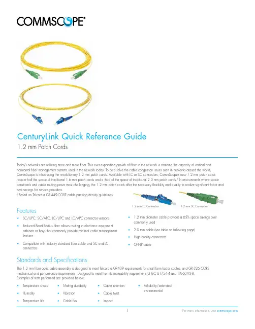
CenturyLink Quick Reference Guide1.2 mm Patch CordsToday’s networks are utilizing more and more fiber. This ever expanding growth of fiber in the network is straining the capacity of vertical and horizontal fiber management systems used in the network today. To help solve the cable congestion issues seen in networks around the world, CommScope is introducing the revolutionary 1.2 mm patch cords. Available with LC or SC connectors, CommScope’s new 1.2 mm patch cords require half the space of traditional 1.6 mm patch cords and a third of the space of traditional 2.0 mm patch cords.1 In environments where space constraints and cable routing prove most challenging, the 1.2 mm patch cords offer the necessary flexibility and quality to realize significant labor and cost savings for service providers.1 Based on Telcordia GR-449-CORE cable packing density guidelines.Features• SC/UPC, SC/APC, LC/UPC and LC/APC connector versions • Reduced Bend Radius fiber allows routing in electronic equipment cabinets or bays that commonly provide minimal cable management features• Compatible with industry standard fiber cable and SC and LC connectors • 1.2 mm diameter cable provides a 65% space savings over commonly used• 2.0 mm cable (see table on following page)• High quality connectors• OFNP cable1.2 mm SC Connector1.2 mm LC ConnectorStandards and SpecificationsThe 1.2 mm fiber optic cable assembly is designed to meet Telcordia GR409 requirements for small form factor cables, and GR-326 CORE mechanical and performance requirements. Designed to meet the intermateability requirements of IEC 61754-4 and TIA-604-3-B. Examples of tests performed are provided below:• Temperature shock • Humidity• Temperature life • Mating durability• Vibration• Cable flex• Cable retention• Cable twist• Impact• Reliability/extendedenvironmentalThe 1.2 mm cable with SC or LC connector is a new fiber optic cable technology with a look-and-feel uniquely different than standard fiber cable.Despite the small diameter, performance is similar to a 1.6 mm or 2.0 mm cable. This is due to the cabling design, which features a proprietary method of bonding the jacket to the cable strength members. The result is a cable assembly with improved capability over standard 1.6 mm or 2.0 mm cable, where pull forces on the cable are distributed to the strength members, as opposed to the cable jacket which can be potentially damaged.OpticalMaximum IL Minimum RL Fiber Height*Apex Offset RadiusUPC: 0.4dB UPC: -55dB UPC: -125 to +50 nm UPC: 50 μm max UPC/SC: 10-25 mm; UPC/LC: 7-25 mmAPC: 0.4dBAPC: -65dBAPC: -100 to +100 nmAPC: 60 μm maxAPC: 5-12 mm* Variations depending on radius, per GR326 recess equation for UPC and IEC 61755-3-2 for APC.Product DimensionsConnector DimensionsSC 1.2 mm ConnectorPatch Cords1 to 15 m +15 m +16 cm/-0 cm +1%/-0 cm48.5 mm (1.91")24-Fiber Bundle 1.2 mm Diameter Cable24-Fiber Bundle 2.0 mm Diameter CablePatch Cord Diameter Cables per Square Inch of Vertical Cable Management Space *3.0 mm 462.0 mm 1021.6 mm 1601.2 mm263* Based on GR-449-CORE, Issue 2 patch cord packingSinglemode 1.2 mm Patch CordsOrdering InformationOrdering information continued on the following page.Singlemode 1.2 mm Patch Cords continuedOrdering InformationOrdering information continued on the following page.Singlemode 1.2 mm Patch Cords continuedOrdering InformationThis CenturyLink Ordering Guide and the information contained within is confidential and restricted for use by CenturyLink personnel only. If you have received this ordering guide in error, any use, reproduction or dissemination is strictly prohibited.Visit our website or contact your local CommScope representative for more information.© 2015 CommScope, Inc. All rights reserved.All trademarks identified by ® or ™ are registered trademarks or trademarks, respectively, of CommScope, Inc.This document is for planning purposes only and is not intended to modify or supplement any specifications or。
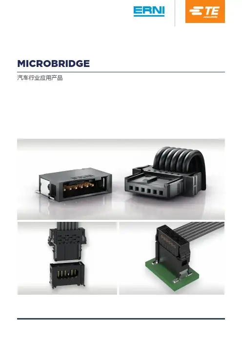
MICROBRIDGE 汽车行业应用产品MICROBRIDGE - 汽车行业应用产品我司一如既往地致力于满足汽车行业客户的要求,继续推出MicroBridge系列产品。
此线对板连接器是根据 VW75174 和 USCAR-2 汽车测试规范开发而成。
MicroBridge 可以满足汽车行业的高标准要求,特别是在连接可靠性方面。
Koshiri 的安全性以及可选的电连接器定位装置 (CPA) 可确保实现安全和正确的连接。
尽管针距仅为 1.27 毫米,但 MicroBridge 非常坚固,其采用双边互锁锁扣,能承受剧烈的车辆振动。
而且,其紧凑型设计非常适合在有限的安装空间中使用。
此连接器的耐受温度高达 150°C,可暴露在严苛温度条件下,例如靠近车前灯 LED 的区域。
单列绝缘刺破式 (IDC) 母连接器提供 90° 和 180° 电缆出线,而专为表面贴 (SMT) 设计的公连接器有直通式和弯角式两种版本可供选择。
不同针数版本可采用不同的颜色和机械编码,使得连接器更容易区分并防止不正确的连接。
技术细节间距 1.27 毫米针数2-20 针 (单列) 可选板材尺寸0.5 毫米针尺寸0.5 x 0.4 毫米单端子额定电流20°C 时最高 9.0 A(2 针版本)端接技术公连接器 SMT母连接器 IDC (绝缘刺破式)电缆IDC 离散电缆 0.35 mm 2连接器单列 SMT 公连接器,垂直式或直角式单列 IDC 母连接器,带 90° 或 180° 电缆出线编码/颜色*黑色(蓝色,绿色,红色可选)汽车标准基于 VW75174 和 USCAR-2 汽车测试规范开发性能直角式或垂直式公连接器 - 带 90° 电缆出线的母连接器垂直式或直角式公连接器 - 带 180°电缆出线的母连接器垂直式或直角式公连接器 - 带 90°电缆出线的母连接器* 由于使用不同的塑料,公母连接器的颜色无法做到完全一致。


P/VⅡ-12交流金属封闭开关设备使用手册安全第一:在开关设备安装使用前请先仔细阅读本使用手册:●开关设备的使用场所应符合电气设备规定的使用条件的要求。
●安装、操作和维护均需由专职电气人员完成,该人员必须接受相应的培训。
●必须保证电气设备的联锁条件和工作规程的适用和安全性。
●有关开关设备的一切操作,都要遵守手册中的相关规定。
●不要超出开关设备正常工作条件下的技术参数中规定的数值。
●手册应放于安装、操作和维护人员方便拿到的地方。
用户的专职人员应对所有影响工作安全的事项负责,并正确管理开关设备。
如果对本操作手册尚有疑问,欢迎向我们提出,我们将提供进一步的咨讯与服务版权所有,本公司保留对此手册的修改权利。
严禁误用及滥用,包括盗版、篡改及断章取义并提供给第三方。
对所有其它渠道获取的咨讯,本公司概不负责。
目录产品概述概述符合标准技术参数外型尺寸和重量正常使用条件产品结构结构特点外壳与隔板手车功能隔室手车室母线室电缆室低压室防误闭锁装置压力释放装置储运与安装运输交货与保管安装安装现场的一般要求基础混凝土地坪上的基础框架柜体安装母线安装电缆连接电力电缆连接控制电缆连接开关装置接地其它事项运行与维护设备运行准备工作起动调试操作断路器手车断路器接地开关负荷开关组合式过电流继电器调试注意事项检查和维护概述检查和维护时间间隔检查维护主要附件VB2真空断路器手车典型接线图1 1 1 1 1 1 2 2 2 2 3 3 3 4 4 4 4 5 5 5 5 5 6 6 7 7 7 7 7 7 7 8 8 8 8 8 8 9 9 10 10 10 10 10 11 11 11 12概 述P/VⅡ-12型铠装移开式户内交流金属封闭开关设备是上海通用电气广电有限公司最新一代的户内成套配电装置。
设备适用于标称系统电压3~10kV,额定电流4000A及以下,额定频率50Hz的单母线或单母线分段三相交流户内配电系统,用于接收和分配电能,并对电路实行控制、保护及监测。
EPA 多路系列硬件AO212使用手册浙江中控技术股份有限公司声明严禁转载本手册的部分或全部内容。
在不经预告和联系的情况下,本手册的内容有可能发生变更,请谅解。
本手册所记载的内容,不排除有误记或遗漏的可能性。
如对本手册内容有疑问,请与我公司联系。
文档标志符定义警告:标示有可能导致人身伤亡或设备损坏的信息。
WARNING: Indicates information that a potentially hazardous situation which, if not avoided,could result in serious injury or death.电击危险:标示有可能产生电击危险的信息。
Risk of electrical shock: Indicates information that Potential shock hazard where HAZARDOUSLIVE voltages greater than 30V RMS, 42.4V peak, or 60V DC may be accessible.防止静电:标示防止静电损坏设备的信息。
ESD HAZARD: Indicates information that Danger of an electro-static discharge to whichequipment may be sensitive. Observe precautions for handling electrostatic sensitive devices注意:提醒需要特别注意的信息。
ATTENTION: Identifies information that requires special consideration.提示:标记对用户的建议或提示。
TIP:Identifies advice or hints for the user.设备安全警示标志下表列出了在设备中使用的安全警示标志符号及描述。
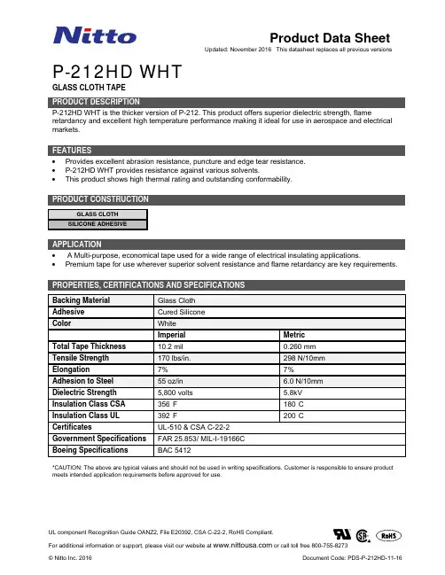
P-212HD WHTGLASS CLOTH TAPEP-212HD WHT is the thicker version of P-212. This product offers superior dielectric strength, flame retardancy and excellent high temperature performance making it ideal for use in aerospace and electrical markets.∙Provides excellent abrasion resistance, puncture and edge tear resistance.∙P-212HD WHT provides resistance against various solvents.∙This product shows high thermal rating and outstanding conformability.GLASS CLOTHSILICONE ADHESIVE∙ A Multi-purpose, economical tape used for a wide range of electrical insulating applications.∙Premium tape for use wherever superior solvent resistance and flame retardancy are key requirements.Backing Material Glass ClothAdhesive Cured SiliconeColor WhiteImperial Metric Total Tape Thickness 10.2 mil 0.260 mmTensile Strength 170 lbs/in. 298 N/10mmElongation 7% 7% Adhesion to Steel 55 oz/in 6.0 N/10mmDielectric Strength 5,800 volts 5.8kVInsulation Class CSA 356°F 180°C Insulation Class UL 392°F 200°C Certificates UL-510 & CSA C-22-2Government Specifications FAR 25.853/ MIL-I-19166CBoeing Specifications BAC 5412*CAUTION: The above are typical values and should not be used in writing specifications. Customer is responsible to ensure product meets intended application requirements before approved for use.Best stored between 50°F-80ºF / 10°C-27ºC, 25-50% relative humidity; out of direct sunlight.Surface should be clean, free of oil, moisture and dirt before applying. Pressure-sensitive adhesive tapes may require pressure by roller, hand or press when applying. Not doing so may affect the general properties and appearance. Please inspect your surface prior to application; this tape may not adhere well to extremely uneven or distorted surfaces. Please remember to allow adequate time for full adhesive strength.The following is made in lieu of all warranties, expressed or implied, including the warranty of merchantability and fitness for a particular or ordinary purpose. Nitto warrants for a period of one (1) year from the date of delivery that products sold to the Customer will be free of defects in workmanship and material. Such warranty will apply only if the Customer notifies Nitto in writing of these defects in reasonable detail, within two (2) weeks after a defect is discovered or should have been reasonably discovered by the Customer. This warranty does not extend i) to products which have been subject to misuse or neglect, ii) to products which have been altered or repaired by personnel other than personnel employed by Nitto or employed by Customer and certified by Nitto or iii) to damage caused, directly or indirectly, by the operation or maintenance performed by any untrained individuals.THIS WARRANTY IS EXCLUSIVE AND IN LIEU OF ANY OTHER WARRANTIES, EXPRESS OR IMPLIED, INCLUDING WITHOUT LIMITATION, WARRANTIES OF MERCHANTABILITY AND FITNESS FOR A PARTICULAR PURPOSE, AND ANY OTHER WARRANTIES ARE HEREBY DISCLAIMED AND EXCLUDED.If the warranty in the first paragraph is breached, the exclusive remedy of Customer and the exclusive obligation of Nitto will be as Nitto elects: to repair or replace the defective product within a reasonable period of time. Return of products to Nitto is allowed only after a Return Material Authorization Number (RMA) has been issued by Nitto. Such RMA will be issued after Nitto receives the notice described in the first paragraph. No shipments of returned products will be accepted without an RMA number. Repair or replacement of the products returned to Nitto will occur only after Nitto has received the returned products and determined that the returned goods were in breach of warranty. Customer will bear all expenses and risk of loss in connection with the return of any products, and Nitto will reimburse Customer for the cost of surface transportation to Nitto of returned products.IN NO EVENT WILL NITTO BE LIABLE FOR ANY CONSEQUENTIAL, INCIDENTAL, OR SPECIAL DAMAGES WHICH ARISE IN CONNECTION WITH THE FAILURE OF, OR DEFECTIVE PERFORMANCE OF, ANY PRODUCT SOLD OR THE BREACH OF WARRANTY EVEN IF NITTO HAD NOTICE OF THE POSSIBILITY HEREOF.Customer’s recovery of any equitable amount or any kind will not be greater than the amount paid for this product. Customer hereby waives all other remedies, statutory or otherwise including the remedies of specific performance or replevin.。
TM221C16R.i s c l ai m e r : T h i s d o c u m e n t a t i o n i s n o t i n t e n d e d a s a s u b s t i t u t e f o r a n d i s n o t t o b e u s e d f o r d e t e r m i n i n g s u i t a b i l i t y o r r e l i a b i l i t y o f t h e s e p r o d u c t s f o r s p e c i f i c u s e r a p p l i c a t i o n sProduct datasheetCharacteristicsTM221C16Rcontroller M221 16 IO relayMainRange of productModicon M221Product or component type Logic controller [Us] rated supply voltage 100...240 V ACDiscrete input number 9 discrete input conforming to IEC 61131-2 Type 1Analogue input number 2 at input range: 0...10 V Discrete output type Relay normally open Discrete output number 7 relay Discrete output voltage 5...125 V DC 5...250 V AC Discrete output current2 AComplementaryDiscrete I/O number16Number of I/O expansion module <= 4 for transistor output <= 4 for relay output Supply voltage limits 85...264 V Network frequency 50/60 Hz Inrush current<= 40 APower consumption in VA <= 46 VA at 100...240 V with max number of I/O expansion module <= 31 VA at 100...240 V without I/O expansion module Power supply output current 0.325 A at 5 V for expansion bus 0.12 A at 24 V for expansion bus Discrete input logic Sink or source (positive/negative)Discrete input voltage 24 V Discrete input voltage type DC Analogue input resolution 10 bits LSB value 10 mVConversion time1 ms per channel + 1 controller cycle time for analog input Permitted overload on inputs+/- 30 V DC for analog input with 5 min maximum +/- 13 V DC for analog input permanentVoltage state1 guaranteed>= 15 V for inputCurrent state 1 guaranteed>= 2.6 mA for fast input>= 4.2 mA for discrete inputVoltage state 0 guaranteed<= 5 V for inputCurrent state 0 guaranteed<= 1.3 mA for discrete input<= 0.6 mA for fast inputDiscrete input current7 mA for discrete input5 mA for fast inputInput impedance 4.9 kOhm for fast input3.4 kOhm for discrete input100 kOhm for analog inputResponse time10 ms turn-on operation for output35 µs turn-off operation for input; I2...I5 terminal10 ms turn-off operation for output5 µs turn-on operation for fast input; I0, I1, I6, I7 terminal35 µs turn-on operation for input; other terminals terminal5 µs turn-off operation for fast input; I0, I1, I6, I7 terminal100 µs turn-off operation for input; other terminals terminal Configurable filtering time0 ms for input12 ms for input3 ms for inputOutput voltage limits125 V DC277 V ACCurrent per output common 6 A at COM 1 termnal7 A at COM 0 termnalAbsolute accuracy error+/- 1 % of full scale for analog inputElectrical durability Inductive AC-15, (cos phi = 0.35) 240 V / 120 VA : 100000 cyclesResistive DC-12, 24 V / 48 W : 100000 cyclesResistive AC-12, 120 V / 240 VA : 100000 cyclesInductive AC-15, (cos phi = 0.35) 240 V / 36 VA : 300000 cyclesResistive AC-12, 120 V / 80 VA : 300000 cyclesInductive (L/R = 7 ms) DC-13, 24 V / 24 W : 100000 cyclesResistive DC-12, 24 V / 16 W : 300000 cyclesInductive (L/R = 7 ms) DC-13, 24 V / 7.2 W : 300000 cyclesInductive AC-14, (cos phi = 0.7) 240 V / 240 VA : 100000 cyclesInductive AC-15, (cos phi = 0.35) 120 V / 60 VA : 100000 cyclesInductive AC-14, (cos phi = 0.7) 240 V / 72 VA : 300000 cyclesInductive AC-15, (cos phi = 0.35) 120 V / 18 VA : 300000 cyclesResistive AC-12, 240 V / 480 VA : 100000 cyclesInductive AC-14, (cos phi = 0.7) 120 V / 120 VA : 100000 cyclesResistive AC-12, 240 V / 160 VA : 300000 cyclesInductive AC-14, (cos phi = 0.7) 120 V / 36 VA : 300000 cycles Switching frequency20 switching operations/minute with maximum load Mechanical durability>= 20000000 cycles for relay outputMinimum load 1 mA at 5 V DC for relay outputProtection type Without protection at 5 AReset time 1 sMemory capacity256 kB for user application and data RAM with 10000 instructions256 kB for internal variables RAMData backed up256 kB built-in flash memory for backup of application and data Data storage equipment 2 GB SD card optionalBattery type BR2032 lithium non-rechargeable, battery life: 4 yrBackup time 1 year at 25 °C by interruption of power supplyExecution time for 1 KInstruction0.3 ms for event and periodic taskExecution time per instruction0.2 µs BooleanExct time for event task60 µs response timeMaximum size of object areas512 %M memory bits512 %KW constant words255 %TM timers255 %C counters8000 %MW memory wordsRealtime clock WithClock drift<= 30 s/month at 25 °CRegulation loop Adjustable PID regulator up to 14 simultaneous loopsCounting input number 4 fast input (HSC mode) (counting frequency: 100 kHz), counting capacity: 32 bitsControl signal type Frequency meterSingle phaseDual phase (pulse/direction)Dual phase (quadrature)Integrated connection type USB port with connector mini B USB 2.0Non isolated serial link "serial 1" with connector RJ45 and interface RS485Non isolated serial link "serial 2" with connector RJ45 and interface RS232/RS485Supply Serial serial link supply at 5 V 200 mATransmission rate 1.2...115.2 kbit/s (115.2 kbit/s by default) for bus length of 15 m - communication protocol: RS4851.2...115.2 kbit/s (115.2 kbit/s by default) for bus length of 3 m - communication protocol: RS232480 Mbit/s - communication protocol: USBCommunication port protocol USB port : USB protocol - SoMachine-NetworkNon isolated serial link : Modbus protocol master/slave - RTU/ASCII or SoMachine-Network Local signalling 1 LED green for SD card access (SD)1 LED red for BAT1 LED green for SL11 LED green for SL21 LED per channel green for I/O state1 LED red for module error (ERR)1 LED green for PWR1 LED green for RUNElectrical connection Mini B USB 2.0 connector for a programming terminalTerminal block, 3 terminal(s) for connecting the 24 V DC power supplyConnector, 4 terminal(s) for analogue inputsRemovable screw terminal block for inputsRemovable screw terminal block for outputsCable length<= 10 m shielded cable for fast input<= 30 m unshielded cable for output<= 30 m unshielded cable for digital input<= 1 m unshielded cable for analog inputInsulation2300 V AC between output and internal logicNon-insulated between analogue inputs500 V AC between input and internal logicNon-insulated between analogue input and internal logic1500 V AC between supply and ground500 V AC between sensor power supply and ground500 V AC between input and ground1500 V AC between output and ground2300 V AC between supply and internal logic500 V AC between sensor power supply and internal logic500 V AC between Ethernet terminal and internal logic2300 V AC between supply and sensor power supplyMarking CESensor power supply DC at 250 mA supplied by the controllerMounting support Top hat type TH35-15 rail conforming to IEC 60715Top hat type TH35-7.5 rail conforming to IEC 60715Plate or panel with fixing kitHeight90 mmDepth70 mmWidth95 mmProduct weight0.346 kgEnvironmentStandards EN/IEC 61010-2-201EN/IEC 61131-2EN/IEC 60664-1Product certifications RCMIACS E10DNV-GLcULusCSALRABSEACEnvironmental characteristic Ordinary and hazardous locationResistance to electrostatic discharge 4 kV on contact conforming to EN/IEC 61000-4-28 kV in air conforming to EN/IEC 61000-4-2Resistance to electromagnetic fields10 V/m ( 80 MHz...1 GHz) conforming to EN/IEC 61000-4-33 V/m ( 1.4 GHz...2 GHz) conforming to EN/IEC 61000-4-31 V/m ( 2...2.7 GHz) conforming to EN/IEC 61000-4-3Resistance to magnetic fields 30 A/m at 50...60 Hz conforming to EN/IEC 61000-4-8Resistance to fast transients2 kV for power lines conforming to EN/IEC 61000-4-42 kV for relay output conforming to EN/IEC 61000-4-41 kV for Ethernet line conforming to EN/IEC 61000-4-41 kV for serial link conforming to EN/IEC 61000-4-41 kV for I/O conforming to EN/IEC 61000-4-4Surge withstand2 kV for power lines (AC) in common mode conforming to EN/IEC 61000-4-52 kV for relay output in common mode conforming to EN/IEC 61000-4-51 kV for I/O in common mode conforming to EN/IEC 61000-4-51 kV for shielded cable in common mode conforming to EN/IEC 61000-4-50.5 kV for power lines (DC) in differential mode conforming to EN/IEC 61000-4-51 kV for power lines (AC) in differential mode conforming to EN/IEC 61000-4-51 kV for relay output in differential mode conforming to EN/IEC 61000-4-50.5 kV for power lines (DC) in common mode conforming to EN/IEC 61000-4-5Resistance to conducted disturbances,induced by radio frequency fields10 Vrms (0.15...80 MHz) conforming to EN/IEC 61000-4-63 Vrms (0.1...80 MHz) conforming to Marine specification (LR, ABS, DNV, GL)10 Vrms (spot frequency (2, 3, 4, 6.2, 8.2, 12.6, 16.5, 18.8, 22, 25 MHz)) conforming to Marine specification (LR, ABS, DNV, GL)Electromagnetic emissionConducted emissions conforming to EN/IEC 55011 power lines (AC), 0.15...0.5 MHz : 79 dBμV/m QP/66 dBμV/m AVConducted emissions conforming to EN/IEC 55011 power lines (AC), 0.5...300 MHz : 73 dBμV/m QP/60 dBμV/m AVConducted emissions conforming to EN/IEC 55011 power lines, 10...150 kHz : 120...69 dBµV/m QP Conducted emissions conforming to EN/IEC 55011 power lines, 150 kHz...1.5 MHz : 79...63 dBμV/m QPConducted emissions conforming to EN/IEC 55011 power lines, 1.5...30 MHz : 63 dBμV/m QP Radiated emissions conforming to EN/IEC 55011 class A 10 m, 30...230 MHz : 40 dBμV/m QP Radiated emissions conforming to EN/IEC 55011 class A 10 m, 200 MHz...1 GHz : 47 dBμV/m QP Immunity to microbreaks10 msAmbient air temperature for operation -10...55 °C for horizontal installation -10...35 °C for vertical installation Ambient air temperature for storage -25...70 °CRelative humidity 10...95 % without condensation in operation 10...95 % without condensation in storage IP degree of protection IP20 with protective cover in place Pollution degree <= 2Operating altitude 0...2000 m Storage altitude 0...3000 mVibration resistance3.5 mm (vibration frequency: 5...8.4 Hz) on symmetrical rail 1 gn (vibration frequency: 8.4...150 Hz) on symmetrical rail 3.5 mm (vibration frequency:5...8.4 Hz) on panel mounting 1 gn (vibration frequency: 8.4...150 Hz) on panel mounting Shock resistance98 m/s² (test wave duration:11 ms)Offer SustainabilitySustainable offer status Green Premium productRoHS (date code: YYWW)Compliant - since 1415 - Schneider Electric declaration of conformity Schneider Electric declaration of conformity REAChReference not containing SVHC above the threshold Reference not containing SVHC above the threshold Product environmental profileAvailableProduct environmental Product end of life instructionsAvailableEnd of life manualProduct datasheetTM221C16R Dimensions DrawingsDimensionsProduct datasheetTM221C16R Mounting and ClearanceMounting on a RailProduct datasheetMounting and ClearanceTM221C16RDirect Mounting on a Panel Surface(1)Install a mounting stripMounting Hole LayoutProduct datasheetTM221C16R Mounting and ClearanceMountingCorrect Mounting PositionAcceptable Mounting PositionIncorrect Mounting PositionProduct datasheetTM221C16R Mounting and ClearanceClearanceDigital InputsWiring Diagram (Positive Logic)(*)Type T fuseWiring Diagram (Negative Logic)(*)Type T fuseConnection of the Fast InputsI0, I1, I6, I7Relay OutputsNegative Logic (Sink)(*)Type T fuse(1)The COM1 and COM2 terminals are not connected internally.(2)To improve the life time of the contacts, and to protect from potential inductive load damage, you must connect a free wheeling diode in parallel to each in B Sink wiring (negative logic)Positive Logic (Source)(*)Type T fuse(1)The COM1 and COM2 terminals are not connected internally.(2)To improve the life time of the contacts, and to protect from potential inductive load damage, you must connect a free wheeling diode in parallel to each in A Source wiring (positive logic)Analog InputsUSB Mini-B ConnectionSL1 ConnectionSL1N.C.: not connected* : 5 Vdc delivered by the controller. Do not connect.SL2 ConnectionN.C.: not connectedPerformance CurvesDerating CurvesEmbedded Digital Inputs (No Cartridge)X :Ambient temperatureY :Input simultaneous ON ratioEmbedded Digital Inputs (with Cartridge)X :Ambient temperatureY :Input simultaneous ON ratioTM221C16R.。
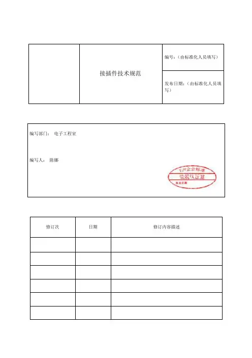
编号:(由标准化人员填写)接插件技术规范发布日期:(由标准化人员填写)编写部门:电子工程室编写人:**修订次日期修订内容描述1 范围本标准规定了汽车电器件使用的接插件的技术要求及试验方法。
本标准适用于汽车用接插件。
2 规范性引用文件下列文件对于本文件的应用是必不可少的。
凡是注日期的引用文件,仅注日期的版本适用于本文件。
凡是不注日期的引用文件,其最新版本(包括所有的修改单)适用于本文件。
GB 252 轻柴油GB 484 车用汽油GB 11118.1 矿物油和合成烃型液压油GB/T 11121 汽油机油JT 225 汽车发动机冷却液安全使用技术条件QC/T 417.1-2001 车用电线束插接器第一部分定义、试验方法和一般性能要求QC/T 417.3-2001 单线片式插接件的尺寸和特殊要求QC/T 417.4-2001 多线片式插接件的尺寸和特殊要求QC/T 417.5-2001 用于单线和多线插接器的圆柱式插接件的尺寸和特殊要求DIN 40 046 第 11 部分通信工程电子元件和设备的气候环境和机械测试;测试 K:腐蚀性空气环境3 术语3.1电线附件电线和插头或插座之间持久的连接物,例如:压接、绝缘替代、焊接等。
3.2接插件插头和插座的统称。
3.3插头插入插座可完成电气连接的接插件(公端子),外形类似针状。
(见图1)3.4插座接受插头形成电子连接的插接件(母端子),外形类似钳状。
(见图2)3.5锁定插座具有自锁和人工解锁功能并吻合于插头上的孔或凹座的插座。
3.6锁销吻合于插头上的孔或凹座,继而锁定插头的插座凸出部分。
3.7二次锁紧插接器有两处锁止结构将其插头或插座锁定在护套内。
3.8插接器把一个或多个端子通过塑壳和辅件连接起来的组装品,完成电气连接的功能。
3.9可拆卸连接两个配合的接插件连接(见图3)。
3.10多线连接两个配合的插接器和多对插头和插座的连接(见图4)。
3.11不可拆卸连接(压接连接)可使用机器或手动钳在插头或插座与导线之间通过压接进行不可拆卸的无焊电气连接。
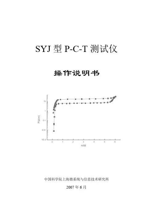
SYJ 型P-C-T 测试仪操作说明书中国科学院上海微系统与信息技术研究所2007年6月P (a t m )H/M警告:1.任何人在操作本设备前必须熟读本说明书,并经过设备供应商的技术培训。
2.本设备操作人应熟悉氢气的安全操作规程和储氢合金在氢化前后的安全知识。
3.本设备的安装和使用现场不允许有明火或易燃性气体存在。
4.本设备的安装和使用现场应在高处安装向室外排气的装置,如排气风扇。
5.本设备安装和使用现场的所有电器、照明应采用防爆装置。
6.氢气瓶在实验结束后应关闭其阀门。
7.本设备操作人员应经常检查整个氢气线路和设备的密封情况,如发现有泄漏,应及时采取措施。
8.操作人员如确有自己解决不了的问题,应及时与供应商联系,在供货商的指导下进行操作,不得擅自对设备进行拆卸。
未经供应商同意私自拆卸所产生一切后果供应商不予负责。
9.本设备在正常状态下运行是安全可靠的。
因此,本设备供应商对于因操作失误而产生的设备的损坏、人员的伤亡及其他事故不负任何责任。
目录1、设备简述(P-C-T原理)2、设备的安装调试3、主要部件及其功能3.1 氢源3.2 温度控制系统3.3 反应器3.4 电源3.5 真空系统3.6 电磁阀3.7 压力传感器3.8 定容器3.9 压力保护开关4、P-C-T的操作4.1 氢气源与真空4.2 样品的制备4.3 温度设定4.4 计算机操作4.5 手动操作4.6 关机5、设备的维护5.1 实验室恒温与排气5.2 捡漏5.3 原器件的更换6、常见问题及处理方法7、附件:设备参数1、设备简述P-C-T 测试仪是储氢合金研究的重要仪器,任何一种储氢合金,如AB5型能在温和条件下吸收大量氢气而形成金属氢化物,其吸收的氢气的体积可以达到其本身体积的1000倍,而且在适当的条件下它又可以将吸收的氢气释放出来,如此循环。
当储氢合金做成Ni/MH 电池负极时,由于它的上述性能,就可以进行充放电反应,在充电时负极合金吸收氢,放电时负极放出氢,如此往复循环,是NI/MH 电池有了充放电循环寿命。
In This Section…Overview............................................................................K-2–K-3Insulating Piercing ConnectorsSplices..........................................................................K-4–K-5Ring Terminals......................................................................K-6Fork Terminals......................................................................K-7Disconnects..........................................................................K-7Taps.....................................................................................K-8Washers...............................................................................K-8Magnet Wire Ordering Information........................................K-8Manual Installation Tools............................................................K-9Battery-Powered Crimping Tool................................................K-10Air Hydraulic Tools..........................................................K-11–K-13Cross Reference.......................................................................K-14InsulationPiercing ConnectorsInsulation Piercing ConnectorsUnited States Tel:901.252.8000800.816.7809Fax:901.252.1354Technical Services Tel:888.862.3289OverviewThe tough, high-temperature insulation on magnet wire used by electrical motor and transformer manufacturers creates problems in splicing and terminating. The durability of magnet wire insulation has made dip-soldering or brazing extremely difficult without stripping the insulation. Another splicing and terminating challenge involves the use of aluminum for magnet applications. A manufacturer connecting aluminum magnet wire to copper is faced with the problem of the different coefficients of thermal expansion of the two metals, galvanic corrosion, cold flow, and the rapid formation of oxide film on the wire surface.T&B offers a solution for a highly reliable connection method for magnetwire. It eliminates welding, no longer requires removal of insulation, and it can be installed in seconds. No special operator skills are needed. The connector and matching tooling do the entire job. To meet the essential requirements of magnet wire connections, T&B offers the insulation piercing Dragon Tooth ®compression connector.Splice, tap and terminate magnet wire quickly and easily!Dragon Tooth ®Magnet Wire ConnectorsThomas & Betts Dragon Tooth ®connectors and installing tools are designed to splice, tap,and terminate magnet wire from 32 AWG to 460,000 CMA copper and from 20 AWG to 460,000 CMA aluminum conductors in motor and transformer applications. Dragon Tooth ®Magnet Wire Connectors penetrate the insulation and oxide layers to make electrical contact on magnet wiring. The result is permanent, low-resistance electrical connections,capable of maintaining contact integrity throughout the life of the connection.•Designed to penetrate magnet wire insulation during application,eliminating the need for stripping, brazing, welding, or other methods of joining magnet wire •Can be installed in seconds•Requires minimal training for installation•Made of copper alloy, tin plated, with teeth on the inner surface •Splices and taps have an open side enabling easy access to wire and making internal coil tapping possible•For aluminum to copper, aluminum to aluminum, or copper to copper magnet wire connections•Supplied with bolt holes to accommodate No. 6 through 1⁄2" studs and includes male and female .250 x .032" disconnects•Splices and fork terminals accommodate wire sizes 24 AWG to 12AWG in a variety of combinations, including combining magnet wire with stripped wire lead. For solid or stranded wire #20 to #4/0 AWG •Larger connectors accommodate circular mil range from 50,000 to 460,000 cm•Connector and matching tooling do the entire jobI n s u l a t i o n P i e r c i n g C o n n e c t o r sTransformer manufacturers depend on Dragon Tooth ®connectorsfor reliable magnet wire applications.Typical ApplicationsParallel SpliceTapTerminationSpliceK-2United States Tel:901.252.8000800.816.7809Fax:901.252.1354Technical Services Tel:888.862.3289OverviewDragon Tooth ®connectors transform the perpendicular compression force, which would normally contribute to conductor creep, into distributive forces that effectively resist cold flow, as indicated by the illustration below .These connectors are made of copper alloy, tin plated, with a number of teeth on the inner surface. When compressed onto an insulated magnet wire, the sharp,hardened teeth penetrate both the insulation and oxide and bite into the conductor.An electrically sound, low-resistance connection is established as a result of the combination of high pressures at the edges of the teeth, and the sliding action between the teeth and the conductor. The open barrel design permits midspansplicing and tapping.How to Select a ConnectorDetermine total circular mil area (CMA). All wires to be installed in a connector barrel including stripped, stranded wire. For example, two #6 AWG = 52480CMA.Refer to Circular Mil column of chart and find the connector series corresponding to the total CMA. For example, 204XXX.Next, refer to either Round Wire column or Rectangular Wire column, depending on the type you are using, and check for any limitations, (such as max. wire width/height). If there are limitations, you may have to make a selection from the next larger size.Select the tool and die appropriate for the application.Insulation Piercing Connectors1234Dragon Tooth ®connectors transform the perpendicular compression force,which would normally contribute to conductor creep, into distributive forces that effectively resist cold flow.These connectors are made of copper alloy, tin plated, with a number of teeth on the inner surface. When the connector is compressed onto an insulated magnet wire, the sharp, hardened teeth penetrate the insulation and the oxide and bite into the conductor. An electrically sound, low-resis t ance connection is established as a result of the combination of high pressures at the tip and edges of the teeth, and the sliding action between the teeth and the conductor.For wire sizes and combinations other than shown, contact Thomas & Betts Technical Services at 800-888-0211, ext. 8324.For square or rectangular wire:Thickness x Width x 1.273 x 106= CMAFor round wire:Diameter 2x 106= CMA(or see chart on p. K-8)Formula for Calculating Circular Mil Area (CMA)K-3United States Tel:901.252.8000800.816.7809Fax:901.252.1354Technical Services Tel:888.862.3289Insulating Piercing ConnectorsSplices•Penetrate all standard copper and aluminum magnet wire insulations•Perfect for heavy Formvar, poly-thermaleze,polyester, and polyurethane insulationsROUND WIRE RECTANGULAR DIMENSIONS (IN.)CIRCULAR RANGE (AWG)WIRE RANGE (IN.)PKG.CAT NO.A B C D*MIL AREAMIN. MAX.THICKNESSWIDTHQTY.214420.43.25.22.135–21 (4) - 13 (2)––1000220004.17.11.08.03468 – 1,72432 - 24**––†8400†220001.34.17.14.091,277 – 4,20526 - 17**.02 - .04.02 - .09†3000†220002-TB .34.25.18.092,985 – 6,68724 - 14**.02 - .05.02 - .10†3000†220006.47.25.19.095,162 – 12,33016 - 12.05 - .08.05 - .16†2500†22L004.15.11.09.03128 – 2,02832 - 24**––100022L001.32.16.16.10808 – 5,16226 - 17**.02 - .04.02 - .10100022L002.32.25.19.102,048 – 9,11024 - 15**.02 - .05.02 - .11100022L006.44.25.22.132,580 – 12,33016 - 12.05 - .08.05 - .16100022L008.70.50.35.1312,960 – 30,55018 - 14.04 - .06.06 - .3810022L009.70.55.46.2036,120 – 86,00016 - 5.08 - .18.08 - .3810022L010.70.78.71.2269,750 – 173,090 (f)–.10 - .23 (GU) .10 - .18 (AL).30 - .63210214S .63.38.37.174,110 – 20,76014(a) - 10.08 - .09.08 - .182********S .69.53.53.2510,380 – 52,48012(b) - 4(e).10 - .16.10 - .26100204210SH .69.53 1.05.4820,760 – 104,96012(c) - 2(d).10 - .16.10 - .2610022L009H .70.55.93.3772,000 – 132,00016 - 5.08 - .18.08 - .38100220015 1.50.88.77(e)50,000 – 115,00010 - 6.100 - .175.300 - .62550220019 1.50 .88 .85(e)110,000 – 175,000 6 - 2.175 - .250.300 - .62525220023 1.75.88.93(e)165,000 – 230,000 2 - 1/0.250 - .325.300 - .62525314118S .63.38.30.143,260 – 12,33015 - 13.05 - .06.05 - .182******** 3.13 .88 .77(e)50,000 – 115,00010 - 6.100 - .175.300 - .62525220020 3.13.88.85(e)110,000 – 175,000 6 - 2.175 - .250.300 - .62525220024 3.63.88.93(e)165,000 – 230,000 2 - 1/0.250 - .325.300 - .62525BCADFor special insulations, consult Technical Services.*Reference dimension. See installing die illustration for gauging.** Not recommended for aluminum magnet wire finer than 21 gauge. (a) Four wires max. (b) Six wires max. (c) Six wires max.each barrel (d) Conductors heavier than 6 AWG require special dies. Contact Thomas & Betts for assistance.(e) Crimping dies may not bottom. Connector height will depend on number and size of wires in barrel. Pump must deliver 9800 psi minimum. (f) Copper CMA, aluminum CMA=52,136–124,561.† On a reel(a) This space may be used for terminal tongue insert, stripped stranded copper wire, stripped copper magnet wire, or left empty.NOTE:Wire sizes and combinations shown have been tested to and meet or exceed Thomas & Betts specifications. Connectors may be suitable for other wire sizes or combinations. Thomas & Betts sells these connectors with the understanding that the user will perform necessary tests to determine their suitability for the intended purpose.I n s u l a t i o n P i e r c i n g C o n n e c t o r sSplices for copper and aluminum magnet wire!123456789123456789K-4United States Tel:901.252.8000800.816.7809Fax:901.252.1354Technical Services Tel:888.862.3289Insulating Piercing ConnectorsSee note (a).BECABD ECA(a) This space may be used for terminal tongue insert, stripped stranded copper wire, stripped copper magnet wire, or left empty.NOTE:Wire sizes and combinations shown have been tested to and meet or exceed Thomas & Betts specifications.Connectors may be suitable for other wire sizes or combinations. Thomas & Betts sells these connectors with the understanding that the user will perform necessary tests to determine their suitability for the intended purpose.Insulation Piercing ConnectorsSplices (continued)101110111110Lower Half .10 - .25.10 - .92Upper Half .25 max 1.03 max.Lower Half .08 - .15.08 - .49Upper Half .25 max .75 max.For Conn 210214MT For Conn204210MTROUND WIRERECTANGULAR STUD DIMENSIONS (IN.)CIRCULAR RANGEWIRE RANGE (IN.)PKG.CAT. NO.SIZEABCDEMIL AREA(AWG)THICKNESS WIDTHQTY.210214MT –.63.63.75.25.1920,000 – 105,000 5 - 13250210MT141/4 1.00 1.44.81–.08 5 - 1325210MT383/8 1.00 1.44.81–.08 5 - 1325204210MT –.69.941.03.25.2590,000 – 215,000 3 - 10100204MT141/4 1.00 1.44.91–.10 3 - 1025204MT383/81.00 1.44.91–.103 - 1025K-5United States Tel:901.252.8000800.816.7809Fax:901.252.1354Technical Services Tel:888.862.3289Insulating Piercing Connectors ROUND WIRERECTANGULARSTUD DIMENSIONS (IN.)CIRCULAR RANGEWIRE RANGE (IN.)PKG.CAT. NO.SIZEABCD*E*MIL AREA(AWG)THICKNESS WIDTHQTY.31412510.38.56 1.22.41.143,260 - 12,33015 - 13.05 - .06.05 - .182503141231⁄4".38.56 1.41.41.143,260 - 12,33015 - 13.05 - .06.05 - .182502102198.38.56 1.22.41.174,110 - 20,76014(a) - 10.08 - .09.08 - .1825021021710.38.56 1.22.41.174,110 - 20,76014(a) - 10.08 - .09.08 - .182502102161⁄4".38.56 1.41.41.174,110 - 20,76014(a) - 10.08 - .09.08 - .1825020421710.53.61 1.58.50.2510,380 - 52,48012(b) - 4(c).10 - .16.10 - .261002042121⁄4".53.61 1.58.50.2510,380 - 52,48012(b) - 4(c).10 - .16.10 - .26100210214-11⁄4".38.56 1.41.69.174,110 - 20,76014(a) - 10.08 - .09.08 - .182********-25⁄16".38.56 1.41.69.174,110 - 20,76014(a) - 10.08 - .09.08 - .182********-33⁄8".38.56 1.41.69.174,110 - 20,76014(a) - 10.08 - .09.08 - .182********-11⁄4".53.61 1.58.81.2510,380 - 52,48012(b) - 4(c).10 - .16.10 - .26100204210-25⁄16".53.61 1.58.81.2510,380 - 52,48012(b) - 4(c).10 - .16.10 - .26100204210-33⁄8".53.61 1.58.81.2510,380 - 52,48012(b) - 4(c).10 - .16.10 - .26100204210-51⁄2".53.61 1.58.81.2510,380 - 52,48012(b) - 4(c).10 - .16.10 - .26100204210-1H 1⁄4".53.61 1.58.81.4720,760 - 104,96012(b) - 4(c).10 - .16.10 - .26100204210-3H 3⁄8".53.61 1.58.81.4720,760 - 104,96012(b) - 4(c).10 - .16.10 - .261002200173⁄8".88 1.50 2.76 1.06(d)50,000 - 115,000.100 - .175–.300 - .625252200181⁄2".88 1.50 2.76 1.06(d)50,000 - 115,000.100 - .175–.300 - .625252200213⁄8".88 1.50 2.76 1.06(d)110,000 - 175,000–.175 - .250.300 - .625252200221⁄2".88 1.50 2.76 1.06(d)110,000 - 175,000–.175 - .250.300 - .625252200253⁄8".88 1.50 2.76 1.06(d)110,000 - 230,000- .175 - .325.300 - .625252200261⁄2".88 1.50 2.76 1.06(d)110,000 - 230,000- .175 - .325.300 - .6252522R061**6.16.32.78.30.10404 - 410015 - 24.02 - .05.02 - .10100022R081**8.16.32.78.30.10404 - 410015 - 24.02 - .05.02 - .10100022R101**10.16.32.78.30.10404 - 410015 - 24.02 - .05.02 - .10100022R0868.25.45.91.30.132,580 - 12,33012 - 16.05 - .08.05 - .16100022R10610.25.45.91.30.132,580 - 12,33012 - 16.05 - .08.05 - .16100022R1461⁄4".25.45.95.42.132,580 - 12,33012 - 16.05 - .08.05 - .16100022L010*BDCAE*Reference dimension. See installing die illustration for gauging. (a) Four wires max. (b) Six wires max. (c) Conductors heavier than 6 AWG require special dies. Contact Thomas & Betts for assistance. (d) Crimping dies may not bottom.Connector height will depend on number and size of wires in barrel. Pump must deliver 9800 psi minimum.NOTE:Wire sizes and combinations shown have been tested to and meet or exceed Thomas & Betts specifications.Connectors may be suitable for other wire sizes or combinations. Thomas & Betts sells these connectors with the understanding that the user will perform necessary tests to determine their suitability for the intended purpose.**22-24 AWG and equivalent rectangular c.m.a., copper only.Ring TerminalsSecure connections easily!1234561112234556I n s u l a t i o n P i e r c i n g C o n n e c t o r sK-6United States Tel:901.252.8000800.816.7809Fax:901.252.1354Technical Services Tel:888.862.3289Insulating Piercing ConnectorsConnectors for every application!Durable and convenient!Fork TerminalsDisconnectsBDCAEBDCAEROUND WIRERECTANGULAR STUD DIMENSIONS (IN.)CIRCULAR RANGEWIRE RANGE (IN.)PKG.CAT. NO.SIZEABCD*E*MIL AREA(AWG)THICKNESS WIDTHQTY.22F061**6.16.32.78.30.10404 - 410015 - 24.02 - .05.02 - .10100022F081**8.16.32.78.30.10404 - 410015 - 24.02 - .05.02 - .10100022F101**10.16.32.78.30.10404 - 410015 - 24.02 - .05.02 - .10100022F0666.25.45.91.30.132,580 - 12,33012 - 16.05 - .08.05 - .16100022F0868.25.45.91.30.132,580 - 12,33012 - 16.05 - .08.05 - .16100022F10610.25.45.91.30.132,580 - 12,33012 - 16.05 - .08.05 - .161000210219F 6.25.45.91.30.132,580 - 12,33012 - 16.05 - .08.05 - .161000210217F 8.25.45.91.30.132,580 - 12,33012 - 16.05 - .08.05 - .161000210216F10.25.45.91.30.132,580 - 12,33012 - 16.05 - .08.05 - .161000ROUND WIRERECTANGULAR TAB DIMENSIONS (IN.)CIRCULAR RANGEWIRE RANGE (IN.)PKG.CAT. NO.SIZEABCD*E*MIL AREA(AWG)THICKNESS WIDTHQTY.22LM01**.250 x .032.16.32.76.25.10404 - 410015 - 24.02 - .05.02 - .10100022LM06.250 x .032.25.45.91.25.132,580 - 12,33012 - 16.05 - .08.05 - .16100022LF01**.250 x .032.16.32.79.25.10404 - 410015 - 24.02 - .05.02 - .10100022LF06.250 x .032.25.45.91.25.132,580 - 12,33012 - 16.05 - .08 .05 - .161000*Reference dimension. See installing die illustration for gauging. (a) Four wires max. (b) Six wires max. (c) Conductors heavier than 6 AWG require special dies. Contact Thomas & Betts for assistance. (d) Crimping dies may not bottom.Connector height will depend on number and size of wires in barrel.NOTE:Wire sizes and combinations shown have been tested to and meet or exceed Thomas & Betts specifications.Connectors may be suitable for other wire sizes or combinations. Thomas & Betts sells these connectors with the understanding that the user will perform necessary tests to determine their suitability for the intended purpose.**22-24 AWG and equivalent rectangular c.m.a., copper only.12121212Insulation Piercing ConnectorsK-7United States Tel:901.252.8000800.816.7809Fax:901.252.1354Technical Services Tel:888.862.3289Insulating Piercing Connectors WashersTeeth on the transition washersTapsQuick and easy connections!ConductorsBCASTUD DIMENSIONS (IN.)CAT. NO.SIZE (IN.)ABCAdditional Magnet Wire Ordering Information1. For wire sizes and combinations other than shown,consult factory.2. Maximum of two layers of conductors in each connector.3. Consult factory for gauging other than shown.4. When terminating wires with an AWG size difference of four or more, samples should be tested in completed e c t o r sManual Installation ToolsCrimp with comfort!Ergonomic Manual Installation Tools•Fixed die tool •Incorporates the ergonomically designed Comfort Crimp ®tool handles,which distribute the force more evenly across the hand •Shure-Stake ®mechanism ensures a complete crimp cycle before the tool releases•Rubberisedthermoplastic handles combine maximumERG1806Battery-Powered Crimping Tools •Interchangeable dies can be quickly changed to crimp non-insulated and insulated terminals up to 6 AWG •Dies are the same as our hand tools—crimps will be exactly the same between Sta-Kon ®hand tools such as our ERG-2001 and the new BAT22-6•360° rotating head gives the user the added flexibility when crimping hard-to-reach connections•Short cycle time equates to crimping times of less than two seconds•Quick, lightweight, and maneuverable•NiCd battery operation provides long-lasting battery life to complete up to 150 crimps on a single charge•Extra battery and charger are included with the tool, ensuring round-the-clock operation •Battery charger provides full battery life in under an hour •Linear crimping motion gives a symmetric, high-quality crimp every timeBattery-Powered Crimping Tool —BAT22-611⁄2tons of grip that weighs less than three pounds!Crimping Force —2,900 lbs. max.Wire Crimping Range —Up to 6 AWG Crimp Cycle Time —2 seconds Power Supply —9.6V NiCd battery Recharging Time —1 hourCrimps per Charge —150Dimensions —25.4" (645 mm) Length 3.1" (79 mm) Width 2.1" (53 mm) Height Tool Weight (With Battery) —23⁄4lbs.CAT. NO. DESCRIPTION PKG. QTY.BAT22-6Battery Crimping Tool 1.5 Ton with 120 VAC Charger 1Crimp Dies*DIE180122 F,L,R-1 Series 1DIE180222L0021DIE180422L0041DIE180622 F,L,R-6 Series1Tool purchase includes crimping tool, two 9V batteries, charger, and case.*Dies sold separately.Easy to rotate with your wrist—delivers fast and effective crimping power.. . . . . . . . . . . . . . . . . . Specifications . . . . . . . . . . . . . . . . . .T&B’s newest battery-powered tool is fast and portable for making high-volume and difficult-to-reach terminal installations in a snap. The BAT22-6 delivers 1.5 tons of crimping force with an easy, pushbutton trigger. The lightweight, ergonomic design minimizes the risk of repetitive motion injuries that can occur with traditional hand crimping tools. And at less than three pounds, one-hand operation is easy while still packing enough power to crimp up to 6 AWG terminals in seconds.Included Accessories•Sturdy, plastic carrying case for portability •Two 9.6V NiCd batteries and battery charger •Sturdy tray for convenient storage of crimp diesUses the exact dies of theComfort Crimp line of ergonomic tools for Sta-Kon, Spec-Kon, and Dragon Tooth.I n s u l a t i o n P i e r c i n g C o n n e c t o r sK-10United States Tel:901.252.8000800.816.7809Fax:901.252.1354Technical Services Tel:888.862.3289Air Hydraulic ToolsPneumatic power!Continuous reel crimping!Perfect for high-speed installation!Installing Dies for BAIR22-6and PAIR22-6PAIR22-6 — Heavy-Duty Portable Air Crimp Tool•Installs Dragon Tooth ®terminals •Hand actuated•Delivers 1.25 tons of crimping force at 100 psi • 3 interchangeable dies can crimp the 22xxx1, 22xxx2, and 22xxx6 series terminalsAuto-Feed Tool for Magnet Wire Connectors on Strip•Foot pedal contains T&B Shure-Stake ®control mechanism, which ensures a full compression each time •Insulation piercing connectors are fed on a continuous reel-mounted strip •Dies are self-contained •Includes foot valve, hoses, and air treatment system •Pneumatic bench-mounted foot-operated tool for crimping copper or aluminum magnet wire and copper lead wire, not solder dipped or bondedBAIR22-6 — Heavy-Duty Bench-Top Air Crimp Tool•Bench mounted for stability and operator control •Compact size, all-metallic construction •Delivers 1.8 tons of crimping force at 100 psi •Heavy-duty and installs wide range of Dragon Tooth connectors PAIR 22-6CAT. NO.DESCRIPTIONPAIR22-6Open “C” Yoke; Hand ActuatedCAT. NO.DESCRIPTIONBAIR22-6Equipped with Shure-Stake ®Mechanism, Ensuring Full Crimp Cycle Before ReleaseCAT. NO.CONNECTORQUANTITY PER REELWEIGHT WIDTHDEPTHHEIGHT13676A 2200049,00019 lbs.5"14"11"136782200013,00028 lbs.6"18"14"136792200023,00028 lbs.6"18"14"136962200062,50032 lbs.6"18"16"BAIR22-6CAT. NO.DESCRIPTIONPKG. QTY.Crimp Dies*DIE180122 F,L,R-1 Series 1DIE180222L0021DIE180422L0041DIE180622 F,L,R-6 Series 1. . . . . . . Specifications . . . . . . . .Height —12"Operating Pressure —85–100 psi Base —8" Square Weight —17 lbs.. . . . . . . . . . . . . . . Specifications . . . . . . . . . . . . . .Overall Length — 14"Diameter —21⁄4"Operating Pressure —90–100 psi Weight —2.5 lbs.Insulation Piercing ConnectorsUnited States Technical ServicesAir Hydraulic Tools 6-Ton Hydraulic Head•Lightweight design—weighs less than 7 lbs. including dies •Includes steel carrying caseRugged and portable!CAT. NO.DESCRIPTIONPKG. QTY13100ARemote 14-Ton Hydraulic Head (Dies Ordered Separately)1See die chart on page K-14for complete listing of dies and connectors used with 13100A.Die Release KnobRetainer PinCAT. NO.DESCRIPTIONTBM6HThe TBM6H Remote Hydraulic Crimping Head is a lightweight but powerful compression tool. The TBM6H operates from any 10,000 psi hydraulic pump.See die chart on page K-14for complete listing of dies and connectors used with TBM6H.. . . . . . . . . . . . . . . . . . Specifications . . . . . . . . . . . . . . . . . .CAT. NO.DESCRIPTIONPKG. QTY.1340012-Ton Hydraulic Head (Dies Ordered Separately)1See die chart on page K-14for complete listing of dies and connectors used with 13400.Output — 12 tons (nominal)Hydraulic Operating Pressure — 10,000 psi (max.)Length (with coupling)— 141⁄2"Width — 31⁄4"Weight (without dies) — 15 lbs.. . . . . . . . . . . . . . . . . . Specifications . . . . . . . . . . . . . . . . . .Output Force — 6 tons nominalOperating Pressure — 10,000 psi nominal (safety bypass on pump set at 9800 psi)Tool Weight — 61⁄2lbs. (without dies)Tool Dimensions — 131⁄2" long, 31⁄2" wide •Tool carrying case included •Dies are ordered as a set (2 pieces)•Upper and lower dies are identical. . . . . . . . . . . . . . . . . . Specifications . . . . . . . . . . . . . . . . . .Lightweight design!14-Ton Hydraulic Head•14 tons output (nominal)•10,000 psi max. hydraulic operating pressure •Weighs 10 lbs.Powerful and reliable!12-Ton Hydraulic Head•12 tons output (nominal)•10,000 psi max. hydraulic operating pressure •Weighs 15 lbs.I n s u l a t i o n P i e r c i n g C o n n e c t o r sOutput — 14 tons (nominal)Hydraulic Operating Pressure — 10,000 psi (max.)Length (With Coupling)— 111⁄2in.Width — 21⁄2"Height — 41⁄4"Piston Diameter — 1.812"Piston Stroke — 1.5" max.Weight (Without Dies)— 10 lbs.Air Hydraulic Tools15-Ton Hydraulic Head•Longer, slimmer profile enables easier access into tight spaces •Wider jaw opening eases crimping of larger connectors •Head made of forged steel and insulated with rubber boot •Steel carrying case is included•Longer, slimmer profile enables easier access into tight spaces Crimp larger connectors easily!CAT. NO.DESCRIPTIONPKG. QTYTBM15IInsulated 15-Ton Hydraulic Tool; Carrying Case Included 1See die chart on page K-14for complete listing of dies and connectors used with TBM15I.15500-TB AdapterCAT. NO.DESCRIPTION13810Electric hydraulic pump, 10000 psi with Shure-Stake mechanism feature; this is a heavy-duty OEM pump with high flow rate; 115V, 60Hz, 11⁄2HP, 23A; requires hand or foot control.You may also need…13611Hand Switch for 1381013612Foot Switch for 1381013613High Pressure, Steel Reinforced Hydraulic Hose; 6 ft.13614High Pressure, Steel Reinforced Hydraulic Hose; 10 ft.13619High Pressure, Plastic Hydraulic Hose; 10 ft.13600This electric hydraulic pump is for use with all T&B hydraulicheads—consists of pump with pressure gauge and Pioneer type male coupler; add suffix WG to eliminate gauge; output pressure 9800 psi; order switch and hose separately.You may also need…13620Hand Switch—10 ft.13589A Foot Switch—10 ft.1361910-ft. Non-Metallic Hose 1361820-ft. Non-Metallic HoseA remote control switch is required. Order Cat. No. 13620 for hand operation or Cat. No. 13589A for foot operation.All pumps are supplied with a metal carrying case.13610AShure-Stake ®electric hydraulic pump has same features as 13600, but includes the Shure-Stake ®control mechanism; prevents under crimping; (pump pressure must reach 9,800 psi before recycling); requires hand or foot control; order switch and hose separately.You may also need…13611Hand Switch—10 ft.13612Foot Switch—10 ft.13797In-line hydraulic pressure inspection gauge with male and femalepioneer-type coupler.A remote control switch is required to operate this unit. Use either a #13611 (hand) or #13612 (foot) switch.1381013610AElectric Hydraulic Pump•Up to 10,000 psi output pressure •Durable construction •Hand or foot actuatedOutput Force — 15 tons nominal Operating Pressure — 10,000 psi nominal Cylinder — 2" dia.Tool Weight — 161⁄2lbs. (without dies)Installs — 8 AWG – 1500 MCM Copper; 10 AWG – 1000 MCM Aluminum. . . . . . . . . . . . . . . . . . Specifications . . . . . . . . . . . . . . . . . .Insulation Piercing ConnectorsUnited States Technical ServicesCross ReferenceAn easy-to-use reference guide for tools and connectors!AUTOFEED TOOL MANUALBATT 22-6. BAIR 22-6, PAIR 22-6FOR STRIP TBM6H13100A13400TBM15ICONNECTORDIES204210MT –––––13682–204210S ––––13671B 13671A 13671B with 15500TB 204210SH ––––13673B 1367313673B with 15500TB 204210-1––––13671B 13671A 13671B with 15500TB 204210-1H ––––13673B 1367313673B with 15500TB 204210-2––––13671B 13671A 13671B with 15500TB 204210-3––––13671B 13671A 13671B with 15500TB 204210-3H ––––13673B 1367313673B with 15500TB 204210-5––––13671B 13671A 13671B with 15500TB 204212––––13671B 1367113671B with 15500TB 204217––––13671B 13671A 13671B with 15500TB204MT14–––––––204MT38–––––––204T14––––13689B –13689B with 15500TB 204T38––––13689B –13689B with 15500TB 210214MT ––––13681B 1368113681B with 15500TB 210214S ––––13670B 13670A 13670B with 15500TB 210214-2––––13670B 13670A 13670B with 15500TB 210214-3––––13670B 13670A 13670B with 15500TB 210216, 210216F ––––13670B 13670A 13670B with 15500TB 210217, 210217F ––––13670B 13670A 13670B with 15500TB 210219, 210219F ––––13670B 13670A 13670B with 15500TB210MT14–––––––210MT38–––––––214420ERG811/WT811DIE 811–––––220001––13678––––220002-TB ––13679––––220004––13676A ––––220005––13690––––220006––13696––––220015––––13713–137********––––13713–137********––––13713–137********––––13713–137********––––13713–137********––––13713–137********––––13713–137********––––13713–137********––––13713–137********––––13713–137********––––13713–137********––––13713–1371322F061ERG1801DIE1801–––––22F066ERG1806DIE1806–––––22F081ERG1801DIE1801–––––22F086ERG1806DIE1806–––––22F101ERG1801DIE1801–––––22F106ERG1806DIE1806–––––22L001ERG1801DIE1801–––––22L002ERG1802DIE1802–––––22L004ERG1804DIE1804–––––22L006ERG1806DIE1806–––––22L008–––6TON-MW-0813683B 1368313683B with 15500TB 22L009–––6TON-MW-0913684B 1368413684B with 15500TB 22L009H ––––13686B 1368613686B with 15500TB22LF01ERG1801DIE1801–––––22LF06ERG1806DIE1806–––––22LM01ERG1801DIE1801–––––22LM06ERG1806DIE1806–––––22R061ERG1801DIE1801–––––22R106ERG1806DIE1806–––––22R146ERG1806DIE1806–––––314118S ––––13685B 1368513685B with 15500TB 314123––––13685B 1368513685B with 15500TB 314125––––13685B 1368513685B with 15500TB22L010––––13690BI n s u l a t i o n P i e r c i n g C o n n e c t o r sNOTE:Dies that fit 13100A also work in TBM15 with use of adapter 15500TB.。
11658IEC Connector C21, for very hot conditions 155°C, Rewireable, StraightRewireable connectorExample with assembled cableApprovals and CompliancesC21155° CDescription- Cord Connector- Connector , Pin temperature 155 °C , Protection class I - Cable diameter 6.5 - 16 mm - Min. wire size 16AWG / 1.0 mm² - Max. wire size 10AWG / 1.5 mm²Characteristics - Suitable for use in equipment according to IEC/UL 60950Weblinkspdf datasheet , html-datasheet , General Product Information , Distributor-Stock-Check , Accessories , Detailed request for productT echnical DataRatings IEC16 A / 250 VAC; 50 Hz Ratings UL/CSA 20 A / 250 VAC; 60 Hz Dielectric Strength> 1.5 kVAC between L-N > 1.5 kVAC between L/N-PE (1 min/50 Hz)Allowable Operation Tempe-rature-25 °C to 155 °CInsulation cover Suitable for appliances with protection class I acc. to IEC 61140TerminalCableMaterial: HousingThermoplastic, black, UL 94V-0appliance inlet/-outletC21 acc. to IEC 60320-1UL 60320-1, CSA C22.2 no. 60320-1 (for very hot conditions) pin-temperature 155 °C, 16 A, Protection Class IApprovals and CompliancesDetailed information on product approvals, code requirements, usage instructions and detailed test conditions can be looked up in Details about ApprovalsApprovalsThe approval mark is used by the testing authorities to certify compliance with the safety requirements placed on electronic products. Approval Reference T ype: 1658Approval LogoCertificates Certification Body DescriptionVDE Approvals VDECertificate Number: 40039959UL Approvals ULUL File Number: E96454CQC ApprovalsCQCCCC File Number: 2014010204701246Product standardsProduct standards that are referencedOrganizationDesignStandardDescriptionDesigned according to IEC 60320-1Appliance couplers for household and similar general purposes Designed according to UL 60320-1Standard for Attachment Plugs and ReceptaclesDesigned according toCSA C22.2 no. 60320-1General Use Receptacles, Attachment Plugs, and Similar Wiring Devices1658Application standardsApplication standards where the product can be usedOrganization Design StandardDescriptionDesigned for applications acc.IEC/UL 60950IEC 60950-1 includes the basic requirements for the safety of informationtechnologyequipment.CompliancesThe product complies with following Guide LinesIdentification Details Initiator DescriptionCE declaration of conformity SCHURTER AG The CE marking declares that the product complies with the applicablerequirements laid down in the harmonisation of Community legislation onits affixing in accordance with EU Regulation 765/2008.RoHS SCHURTER AG EU Directive RoHS 2011/65/EUChina RoHS SCHURTER AG The law SJ / T 11363-2006 (China RoHS) has been in force since 1 March2007. It is similar to the EU directive RoHS.REACH SCHURTER AG On 1 June 2007, Regulation (EC) No 1907/2006 on the Registration,Evaluation, Authorization and Restriction of Chemicals 1 (abbreviated as"REACH") entered into force.Dimensions [mm]1) Cutting points for 10/12/14/16 mm cable diameterAll VariantsPackaging unit 50 PcsMating Inlets/PlugsCategory / DescriptionAppliance Inlet Overview completeIEC Appliance Inlet C22, for very hot conditions 155°C, Screw-on or Snap-in Mounting, Front Side1681Appliance Inlet further types to 165821658IEC Inlet Filter Overview completeC20F, 20 A, prewired, Standard and Medical Version, Solder, quick connect or wires (stranded), Capacitor: X2, Screw,Mounting Front-/Rear-Side, Power Entry Modules with FilterC22FIEC Inlet Filter further types to 1658The specifications, descriptions and illustrations indicated in this document are based on current information. All content is subject to modifications and amendments. Information furnished is believed3.12.2173。
1-1123722-41-1123722-2.1-1318300-21-1123722-31-1123722-2 1-1123722-81-1123722-51-1318301-21-1318301-21-1318300-4TECHNICAL FEATURES • 3.96mm, 5.08mm, and 7.92mm centerline options • 250 VAC to 600 VAC voltage rating up to 11A • Wire to board, shrouded and unshrouded header configurations• 25°C to + 105°C operating temperature • Meet GWEPT 750°C and UL 94 V0 flamability standards •UL recognizedECONOMY POWER CONNECTOR SERIESQuick Reference GuideTE Connectivity’s (TE) Economy Power (EP) and Economy Power II (EP II) wire-to-board connectors are widely utilized for power circuit applications that require a large current carrying capacity. The connectors feature a 250 VAC (EP) to 600 VAC (EP II) voltage rating at up to 7.5A (EP) and 11A (EP II), which makes themideal for a variety of applications such as household appliances, industrial machinery, and lighting. Additionally, terminal position assurance (TPA) devices are available for the EP II connector series. The EP connector family offers housing and header styles andconfigurations in Glow Wire compatibile material that also meet UL 94 V-0.PRODUCT DETAILSKEY FEATURES • Positive audible latch designed for easier mating and unmating.• Lanceless contacts are available for 22-18 and 20-16 AWG wire ranges for EP II housings• Asymmetrical terminals prevent mis-mating • Polarization tabs help prevent post misalignment • End to end stackable and intermateable to similar competitive products for retrofit applications• Selectively loaded headers on the single row offering are available upon request• T erminal Position Assurance (TPA) devices for EP II •Various colors available upon requestAPPLICATIONS • Household appliances• Industrial machinery (e.g. control boards)• Lighting • HVAC• Commercial & building equipment •Vending machines & coin changersQuick Reference GuideECONOMY POWER PRODUCT OFFERINGHousingsColored housings are available upon request. For more information, contact TE sales representative. Headers**Mating housing P/N X-1744036-Y and contacts 1123721-1 (Phos Bronze - pre tin) 1123721-2 Brass - pre tin).Selectively loaded headers available upon request.ContactEP II Terminal Position Assurance (TPA) - OptionalQuick Reference GuideAPPLICATION TOOLING-2 thru -9: Substitute dash number listed for “Y”, therefore a -2 signifies PN 174416-21--0 thru 1--2: Substitute first number for “X” and second number listed for “Y”, therefore 1--2 signifes PN 1-1744416-2: Follow same numbering scheme throughout for other part numbers listedQuick Reference GuideTE Connectivity, TE Connectivity (logo), and Every Connection Counts are trademarks. All other logos, products and/or company names referred to herein might be trademarks of their respective owners.The information given herein, including drawings, illustrations and schematics which are intended for illustration purposes only, is believed to be reliable. However, TEConnectivity makes no warranties as to its accuracy or completeness and disclaims any liability in connection with its use. TE Connectivity‘s obligations shall only be as set forth in TE Connectivity‘s Standard T erms and Conditions of Sale for this product and in no case will TE Connectivity be liable for any incidental, indirect or consequential damages arising out of the sale, resale, use or misuse of the product. Users of TE Connectivity products should make their own evaluation to determine the suitability of each such product for the specific application.© 2016 TE Connectivity Ltd. family of companies All Rights Reserved.1-1773885-9 08/16 OriginalADDITIONAL RESOURCESTE Connectivity T echnical Support CenterUSA: +1 (800) 522-6752Canada: +1 (905) 475-6222Mexico:+52 (0) 55-1106-0800Latin/S. America: +54 (0) 11-4733-2200Germany: +49 (0) 6251-133-1999UK: +44 (0) 800-267666France: +33 (0) 1-3420-8686Netherlands: +31 (0) 73-6246-999China:+86 (0) 400-820-6015DESIGN-IN QUESTIONS1.What are the current and voltage requirements for your application?The Economy Power connector series has a current rating of 7.5A (EP) 11A (EP II) per line with the on #16 AWG wire and is rated for 250 VAC (EP) and 600 VAC (EP II).2.Are Economy Power II connectors available in various colors and position configurations?Yes. All of the configurations are available in multiple colors. Additionally, EP II offers options of 2 to 12 position single-row wire-to-board.3.Are Economy Power connectors Glow Wire test compliant?Yes. Economy Power connector series products for both EP and EP II are available in a GWT, UL 94 V-0, NF 750°C option that conforms to the flammability requirements of IEC 60335-1 for unattended appliances with connections carrying current of greater than .2 A.4. Can TE’s EP II connectors be used as drop in replacementsfor competitor products?Yes. The EP II connectors can be used to replace similar competitive products for retrofit applications.5.What are the wire size requirements?The EP II connector system can accommodate wires ranging from 16 to 22 AWG (1.4 mm 2 to 0.3 mm 2).6.How can TE’s EP II connectors avoid contact back out?The EP product family offers an optional TPA device that helps to ensure the contacts are fully seated in the housing and remain that way. This helps to avoid downtime and costly service calls when equipment won’t work properly due to a contact that has backed out.7.Do I need new tooling to change from EP to EP II housings?No. The same tooling is used for EP and EP II.1-1318300-41-1123722-41-1123722-2.1-1318300-21-1123722-31-1123722-2 1-1123722-81-1123722-51-1318301-21-1318301-21-1318300-4。
INTERCONTEC PRODUCTS QUICK REFERENCE GUIDEINTERCONTEC CONNECTOR SERIESWith the INTERCONTEC product portfolio, TE Connectivity now offers a large variety of solutions that make connecting easy. Our connectors consist of only a few single parts with a modular architecture which makes them highly compatible and usable in many different combinations. The connector assembly is possible without any tools and particularly easy due to the innovative crown clamp: the shielding mesh can remain uncut. Multiple codings prevent faulty mating of connectors when wiring complex equipment. With know-how and market expertise we challenge existing standards. We take a visionary approach to determine the connector technology of the future to provide our customers with innovative and market oriented solutions. Our connectors follow highly sophisticated engineering principles safeguarding an extremely easy and efficient assembly process. By elaborating highlyuser friendly optimum system solutions which are brought to the market in a very short time we quickly respond to our customers’ needs. This is the key strength of TE’s INTERCONTEC products.INTERCONTEC PRODUCTSCONTENTCONTENTSOverview05 FamiliesProductHighlights 05ProductCategories 05 Product Key18digits 0–6 aFindingNumberTEPart15–digits 07 FindingNumberTEPartaPower Connectors9120809 91510 91712 92314 9406 9581 Signal Connectors6151820 6176232262724 Signal Connectors18 6156172022 62362724 Hybrid Connectors6 723228 740Application Set Up623 30 Series923and723 31 SeriesInnovative Highlightsytec,itec 3232 locktec33 htecSpeedT ec 33NOTESytec, itecQuick lock fastener fully connected with just a click self locking connectionPlugCable connector withcoupling nutlocktec connectorThe freely terminableconnectors with thecharacteristics of a moldedversionytec connectorThe ytec system requiresonly one mounting holePlug, angledAngled cable connectorwith coupling nutsingletec connectorOne single pinpower connectoritec connectoritec is available in all ytec pinlayouts and is compatiblewith all mating ytec plugsBulkheadDevice connector withcoupling nut. Interface: flange,thread, counter nut, etc.htec connectorPower, signal and datain one connectorSpeedTec locking systemQuick lock fastener fullyconnected with justan eighth rotationExtensionCable connector with outsidethread. Additional versionsfor cabinets, walls, etcSignal connectors (6 Series)615, 617, 623, 627Hybrid connectors (7 Series)723, 740PRODUCT FAMILIESHIGHLIGHTSPRODUCT CATEGORIESPower connectors (9 Series)912, 915, 917, 923, 940, 958912 means: size M12 power connectorOVERVIEWytec and itec Self-locking SystemsExtension, angledAngled cable connectorwith outside threadReceptacleDevice connector withoutside threadReceptacle, angledAngled device connectorwith outside threadE ES STB BN NN0020020000323200010001000000TE CONNECTIVITY PART NUMBERINTERCONTEC PART NUMBERIntercontec Part Number: 60.004.11TE Connectivity Part Number: 60-0004-011-000OSpeedTec Plug SpeedTec ExtensionSpeedTec Receptacle angled, rotatableBKA441N00xx100B000BGA442N0000yyyy 000BKUA441NN00xx 100B000BEDA442NN0000yyyy 000BSA440N00xx 100B000BSTA440NN00xx 100B00010 (3+PE+6)BGA462N0000yyyy 000Note: M = Male, F = Femalexx = 08: cable dia. 8.0 - 8.9 mm, 09: cable dia. 8.7 - 9.9 mmyyyy receptacle angled = 100B: flange size 21.6 x 21.6 mm, 101B: flange size 25.7 x 25.7 mmMAIN DIMENSIONS, HOUSING VARIANTSMAIN DIMENSIONS, HOUSING VARIANTSNote: M = Male, F = Femalexx = 31: cable dia. 4.5 - 6.5 mm, 32: cable dia. 6.5 - 8.5 mm, xx = 33: cable dia. 8.5 - 10.5 mm, 34: cable dia. 10.5 - 12.0 mm,yyyy receptacle = 0001: flange size 21.6 x 21.6 mm, 0002: flange size 25.7 x 25.7 mmyyyy double receptacle = 0001: flange size 25.8 x 25.8 mm, 0002: flange size 28.0 x 28.0 mmACCESSORIESPlastic protection capTE: 8A-0033-000-000 IC: 8A.033.007 (6+PE)max. 10A7 (6+PE)14A9 (3+PE+5)1TECHNICAL DATANote: M = Male, F = Femalexx = 87:cable dia. 3.5 - 6.0 mm,85:cable dia. 6.0 - 9.5 mm, 86:cable dia. 9.5 - 12.0 mmyyyy4way = 053A:flange size 21.6 x 21.6 mm,054A:flange size 25.7 x 25.7 mm,055A:flange size 28.0 x 28.0 mm yyyy7/9 way = 051A:flange size 21.6 x 21.6 mm,052A:flange size 25.7 x 25.7 mm,050A:flange size 28.0 x 28.0 mm MAIN DIMENSIONS, HOUSING VARIANTSsingletecACCESSORIES ASSEMBL Y TOOLSPlastic protection capTE: 8A-0029-000-000IC: 8A.029.00FixtureTE: WA-0100-092-000IC: WA10092Fitting tool for insulatorTE: C6-0107-000-000IC: C6.107.00Removing tool for insulatorTE: C4-0022-000-000IC: C4.022.00Positioning insertTE: C0-0249-000-000IC: C0.249.00Metal flange, hingedTE: E0-0194-002-000IC: E0.194.02Metal protection capTE: 8B-0048-0001-000IC: 8B.048.01Metal protection capTE: 8B-0067-001-000IC: 8B.067.01Power crimping machine Strip-crimping machineAUTOMATION OPTIONS• C ontacts on reel and processing with strip crimping machine on request • P ower crimping of turned contacts on requestSpeedTec Receptacle8 (3+PE+4)9 (3+PE+5)1TECHNICAL DATANote: M = Male, F = FemaleXX = 43: cable dia. 4.2 - 6.6 mm, 48: cable dia. 7.5 - 12.0 mm, 42: cable dia. 9.5 - 14.5 mm, 59: cable dia. 14.0 - 17.0 mmMAIN DIMENSIONS, HOUSING VARIANTSBEGA-type yyyy = 0100: flange size 25.7 x 25.7 mm, 0101: flange size 28.0 x 28.0 mm BEDC-type yyyy = 1116: flange size 25.7 x 25.7 mm, 1100: flange size 28.0 x 28.0 mmAUTOMATION OPTIONS• C ontacts on reel and processing with strip-crimping machine on request • P ower crimping of turned contacts on requestsingletecPower crimping machine Strip-crimping machineACCESSORIESMetal flange, hingedTE: E0-0222-002-000IC: E0.222.00Adjusting leverTE: C6-0019-000-000IC: C6.019.00FixtureTE: VB-0005-000-000IC: VB.005.00Assembly tool forcoupling nutTE: C8-0004-000-000IC: C8.004.00Plastic protection capTE: 8B-0070-000-000IC: 8B.070.00Plastic protection capTE: 8B-0071-000-000IC: 8B.071.00ASSEMBLY TOOLSSpeedTec Receptacle angled, rotatableNote: M = Male, F = FemaleXX = 03:cable dia. 7.0 - 9.0 mm,44:cable dia. 9.0 - 16.0 mm,45:cable dia. 16.5 - 25.0 mm MAIN DIMENSIONS, HOUSING VARIANTSAUTOMATION OPTIONSDigital battery crimp toolTE: C0-0313-000-000IC: C0.313.00ACCESSORIESPlastic protection capTE: 8A-0004-000-000IC: 8A.004.00FixtureTE: VC-0004-000-000IC: VC.004.00Fitting toolTE: C5-0018-000-000IC: C5.018.00Metal flange, hingedTE: E0-0058-002-000IC: E0.058.02Metal protection capTE: 8B-0018-001-000IC: 8B.018.01Metal protection capTE: 8B-0022-001-000IC: 8B.022.01ASSEMBLY TOOLS Power crimping machineReceptacleReceptacle, angledNote: M = Male, F = FemaleMAIN DIMENSIONS, HOUSING VARIANTSACCESSORIESPlastic protection cap TE: 8A-0011-000-000 IC: 8A.011.00Removing tool forcontact pinsTE: C4-0005-000-000IC: C4.005.00FixtureTE: VD-0006-000-000IC: VD.006.00Sleeve forremoving toolTE: C4-0008-000-000IC: C4.008.00Metal flange, hingedTE: E0-0189-002-000IC: E0.189.02ASSEMBLY TOOLS12Note: M = Male, F = Femalexx = 31:cable dia. 4.5 - 6.5 mm,32:cable dia. 6.5 - 8.5 mm, xx = 33:cable dia. 8.5 - 10.5 mm,34:cable dia. 10.5 - 12.0 mmMAIN DIMENSIONS, HOUSING VARIANTSACCESSORIESPlastic protection capTE: 8A-0033-000-000IC: 8A.033.00yyyy receptacle = 0001: flange size 21.6 x 21.6 mm, 0002: flange size 25.7 x 25.7 mmyyyy double receptacle = 0001: flange size 25.8 x 25.8 mm, 0002: flange size 28.0 x 28.0 mmNOTESSIGNAL CONNECTORS617Note: M = Male, F = Femalexx = 87:Crown clamp cable dia. 3.5 - 6.0 mm,85:Crown clamp cable dia. 6.0 - 9.5 mm, 86:Crown clamp cable dia. 9.5 - 12.0 mm yyyy receptacle angled = 050A:flange size 21.6 x 21.6 mm,051A:flange size 25.7 x 25.7mm,052A:flange size 28.0 x 28.0 mmACCESSORIESASSEMBL Y TOOLSPlastic protection capTE: 8A-0029-000-000 IC: 8A.029.00FixtureTE: WA-0100-092-000IC: WA10092Fitting tool for insulatorTE: C6-0107-000-000IC: C6.107.00Removing tool for insulatorTE: C4-0022-000-000IC: C4.022.00Metal flange, hingedTE: E0-0194-002-000IC: E0.194.02Metal protection capTE: 8B-0048-0001-000IC: 8B.048.01Metal protection capTE: 8B-0067-001-000IC: 8B.067.01MAIN DIMENSIONS, HOUSING VARIANTSAUTOMATION OPTIONS• C ontacts on reel and processing with strip-crimping machine on request • Power crimping of turned contacts on requestPower crimping machineStrip-crimping machineTECHNICAL DATANote: M = Male, F = Femalexx = 39:cable dia. 4.5 - 8.5 mm,41:cable dia. 6.0 - 10.0 mm, 40:cable dia. 9.5 - 13.2 mm, 73:cable dia. 9.0 - 14.7 mm AEGA-type yyyy = 0101flange size 25.7 x 25.7 mm,0100:flange size 28.0 x 28.0 mmAEGA-type yyyy = 0115flange size 25.7 x 25.7 mm,1100:flange size 28.0 x 28.0 mmMAIN DIMENSIONS, HOUSING VARIANTSACCESSORIESMetal flange, hingedTE: E0-0223-002-000 IC: E0.223.02Plastic flange, hingedTE: E0-0117-000-000IC: E0.117.00Plasticprotection capTE: 8B-0069-000-000IC: 8B.069.00Plasticprotection capTE: 8B-0071-000-000IC: 8B.071.00Plasticprotection capTE: 8A-0002-000-000IC: 8A.002.00ASSEMBL Y TOOLSFixtureTE: VA-0002-000-000IC: VA.002.00Fitting toolfor signal insulatorTE: C6-0111-000-000IC: C6.111.00Removing tool for signal insulatorTE: C4-0016-000-000IC: C4.016.00AUTOMATION OPTIONS• C ontacts on reel and processing with strip-crimping machine on request • Power crimping of turned contacts on requestPower crimping machineStrip-crimping machineMAIN DIMENSIONS, HOUSING VARIANTS Extension ReceptacleNote: M = Male, F = Female xx = 43:cable dia. 4.2 - 6.6 mm,48:cable dia. 7.5 - 12.0 mm, 42:cable dia. 9.5 - 14.5 mm, 59:cable dia. 14.0 - 17.0 mmACCESSORIESFixtureTE: VB-0005-000-000IC: VB.005.00Mounting toolcontact 1 mmTE: C5-0002-000-000IC: C5.002.00Removing toolfor insulatorTE: C4-0017-000-000IC: C4.017.00Metal flange, hingedTE: E0-0222-002-000IC: E0.222.02ASSEMBL Y TOOLSNOTEShtec Receptacle11 (4 + PE + 6)Note: M = Male, F = Femalexx = 48: Crown clamp cable dia. 7.5 - 12.0 mm, 42: Crown clamp cable dia. 9.5 - 14.5 mm, 55: Lamelle clamp cable dia. 7.5 - 12.0 mm 58: Lamelle clamp cable dia. 9.5 - 14.5 mm, 59: Lamelle clamp cable dia. 14.0 - 17.0 mm yyyy extension = 0100 standard, 0200: central mout with counter nut yyyy receptacle and receptacle angled = 0300 flange size 28.0 x 28.0 mm,0200 flange size 25.7 x 25.7 mm, 0100: mounting thread M 25.0 x 1.5 mmMAIN DIMENSIONS, HOUSING VARIANTSACCESSORIESPlasticprotection capTE: 8B-0090-000-000IC: 8B.090.00Metalprotection capTE: 8B-0091-001-000IC: 8B.091.01Colored marking rings for connector housing yellow:TE: A6-0022-F04-000IC: A6.022.F04green:TE: A6-0022-F11-000IC: A6.022.F11red:TE: A6-0022-F10-000IC: A6.022.F10Metal flange, hingedTE: E0-0222-002-000IC: E0.222.02FOR DATA ELEMENT6-pin4-pinOPTION: Data inserts, separately EMI shieldedASSEMBL Y TOOL SET (CASE)TE: C0-0323-000-000IC: C0.323.00Assembly toolTE: C0-0282-000-000IC: C0.282.00Crimping insertTE: C0-0321-000-000IC: C0.321.00Positioner insertTE: C6-0166-000-000IC: C6.166.00htec SpeedTec Plug htec ExtensionHKA503N00xx100P000H82A503NN00xx0100000HSA501N00xx100P000H81A501NN00xx0100000Note: M = Male, F = Femalexx = 03:cable dia. 7.0 - 9.0 mm,44:cable dia. 9.0 - 16.0 mm, 45:cable dia. 16.5 - 25.0 mmMAIN DIMENSIONS, HOUSING VARIANTSFOR CONNECTORSASSEMBL Y TOOL SET (CASE)TE: C0-0323-000-000IC: C0.323.00Fitting toolTE: C5-0018-000-000IC: C5.018.00FixtureTE: VC-0004-000-000IC: VC.004.00FOR DATA ELEMENTAssembly toolTE: C0-0282-000-000IC: C0.282.00Crimping insertTE: C0-0321-000-000IC: C0.321.00Positioner insertTE: C6-0166-000-000IC: C6.166.006-pinOPTION: DATA INSERTS, SEPARATELY EMI SHIELDED Plastic protection capTE: 8A-0004-000-000IC: 8A.004.00Metal flange, hingedTE: E0-0058-002-000IC: E0.058.02Metal protection capTE: 8B-0022-001-000IC: 8B.022.01 ACCESSORIESAPPLICATION SET UP – SERIES 923 AND 623angled receptacle with pinsreceptacle with pinsplug with socketsextension withpins and hinged flange central fixing with pinsplug with socketswith pinsbulkhead connector with socketsDriveinterlocking drag chainAPPLICATION SET UP – SERIES 723DriveMotor #6 interlockablecable carriersreceptacle withfemale contactsplug withmale contactsextension withcentral fixing andfemale contactsplug withmale contactsextensionwith malecontactsplugwithfemalecontactshybrid cableplug withmale contactsplug withfemale contactsplug withmale contactsrecaptacle withmale contactsrecaptacle withfemale contactsrecaptacle angledwith male contactsrecaptacle angled withfemale contacts5 x identical motor cablesplug withfemale contactsextension cable tobridge one motor if notused or out of orderServo motors in daisy chain realized with series 723 htec connectorsAutomatic ytec and itec fastener for easy and safe connections• High-quality industrial connector with metal housing • Flat – narrow – short• Miniaturized size in all three dimensions ensures that the system is compatible even with very small motors • 360 ° EMC shielding• High robustness against shock and vibration • Rotatable by 300 °• Protection rating IP 66 and IP 67The ytec system requires only one mounting hole and is available in two different flange sizes 25 and 28.The ytec system connector can be mounted in 4 differentangles (0 °, 90 °, 180 ° and 270 °). Additionally, after installation, the system is infinitely rotatable by 300 °. Itec is available in all ytec pin layouts and is compatible with all mating ytec plugs. Ytec and the single version itec represents an ultra compact complete system with an automatically locking quick-release fastener for easy and safe connections. The mechanically coded housing in conjunction with colour coding makes any confusion of signal and power plug impossible. Ytec and itec system connectors define a new connector dimension. Miniaturized size in all three dimensions ensures that the system is compatible even with the smallest of motors.Connector housing and plastic shell inseparably coupled after quick and easy locktec asembly• Free assembly without overmold• Opening the connector housing results in destruction • Robust metal housing inside, fully EMC shielded • IP class 66/67•Individual labeling and coloring possibleytec and itec self-locking system:locktec connector system:Save cost with the SpeedTec quick locking system• Hybrid cable assemblies• Pre-wired receptacle connectors for servo motors and drive control components • Pin or socket contacts • Straight or angled receptacles • IP 67, IP 68, IP 69 K • 360 ° EMC shielding• CAT 5 Element separately shielded• High robustness against shock and vibration • Continuously rotatable• SpeedT ec quick connection system • T ouchproof power contactsPower, feedback and communication in one housing• Connected within second-time saving • Highest connection reliability • 360 ° EMC shielding• High robustness against shock and vibration • IP 67, IP 68, IP 69 K• Backwards compatible to threaded connectorsM23 hybrid htec connector:SpeedTec connector:ABOUT TTI, INC. - EUROPETHE SPECIALISTIN ELECTRONICCOMPONENTD ISTRIBUTIONWHY CHOOSE TTI?Founded in 1971, TTI has steadily grown to become a worldleading specialist distributor of electronic components.The company was founded on the premise that passivecomponent purchasing could be made more efficient byoffering product specialization, customer-driven service andproprietary supply chain solutions.GLOBAL DISTRIBUTION CENTRESOur European headquarters is located just outside of Munich, Germany in Maisach-Gernlinden. In total, we have 42.600m² of dedicated warehouse space and local sales and technical support in over 40 locations across Europe. TTI has more than 195,000m² of automated warehousing in North America, Europe and Asia. All are linked into a global warehouse management system that provides superior customer service and overall business efficiencies. Wherever you are in the world, TTI can support you.Year after year, customers rate our inventory availability,on-time delivery and accuracy among the very best in the industry – contact us today to find out what a true specialist has to offer.QUALITY AND RELIABILITYTTI is the first distributor to have all global warehouse locations ISO registered and certified to ISO 9001 and ISO 14001 Standards. TTI Europe is also certified to EN9120/EN9100, IECQ-CECC and ISO/IEC 27001 Standards. Additionally, all of our European sales branches are ISO 9001 certified. TTI has one global documentation system that ensures that every TTI branch and warehouse in the worldfollows the same processes.GLOBAL DISTRIBUTION CENTRES WITH MORE THAN 195,000M2 OF AUTOMATED WAREHOUSING IN NORTH AMERICA, EUROPE AND ASIA.EUROPEAN SALES OFFICESCORPORATE HEADQUARTERSTTI, Inc.2441 Northeast Parkway, Fort Worth, T exas 76106 U.S.A.T: +1 817 740 9000 | F: +1 817 740 9898 E:**********************EUROPEAN HEADQUARTERSTTI, Inc.Ganghoferstr. 34, 82216 Maisach-Gernlinden Germany T: +49 (0) 81 42 66 80 0 | F: +49 (0) 81 42 66 80 490 E:***************.comAustriaViennaT: +43 (0) 18 79 85 90E:**********************.com BeneluxEindhovenT: +31 (0) 40 290 1616E:***********************.com BulgariaVarnaT: +359 52 51 10 59E:*********************.com Czech/Slovak Republic BrnoT: +420 541 126 714E:********************.com DenmarkCopenhagenT: +45 (0) 43 29 35 35E:**************************.com RisskovT: + 45 (0) 38 41 31 00E:**************************.com EstoniaTallinnT: +372 664 81 00E:***********************.com Finland & Baltic Region EspooT: +358 98 94 65 200E:***********************.com FranceBriveT: +33 (0) 5 55 92 92 93E:**********************.com BronT: +33 (0) 472 81 2030E:********************.com BruzT: +33 (0) 2 99 77 60 84E:**********************.comLa CiotatT: +33 (0) 442 84 4142E:*************************.com Montigny Le Bretonneux T: +33 (0) 130 13 7380E:*********************.com GermanyBerlinT: +49 (0) 30 8877 40 200E:**********************.com DortmundT: +49 (0) 2301 91 304 0E:************************.com FrankfurtT: +49 (0) 6102 5999 100E:*************************.com HanoverT: +49 (0) 5 11 7 80 59 0E:************************.com MunichT: +49 (0) 81 42 66 80 110E:**********************.com PforzheimT: +49 (0) 7231 14788 0E:*************************.com HungaryBudapestT: +36 1 40 22 111E:************************.com IrelandT: +44 (0)1494 460000E:***********************.com Israel/Ray-Q Ltd.Airport CityT: +972 3 975 3333E:***************ItalyCivitanova Marche T: +39 0733 81 8655E:*********************.com FlorenceT: +39 (0) 55 094 63 76E:*********************.comMilanT: +39 02 822 521E:*********************.com NaplesT: +39 081 4245719E:*********************.com TrivenetoT: +39 049 7802311E:*********************.com RomeT: +39 0774 57 1302E:********************.com NorwayDrammenT: +47 (0) 92 66 87 66E:**********************.com PolandKwidzynT: +48 (0) 55 279 67 57E:**********************.com PortugalVila Nova de Famalicao T: +351 252 493084E:*************************.com RomaniaCluj NapocaT: +40 (0) 733 339 002E:***********************.com RussiaSaint PetersburgT: +7 (0) 812 4962053E:**********************.com South AfricaPretoriaT: +27 86 111 2844E:***************************.com SpainBarcelonaT: +34 (0) 93 645 25 75E:*************************.com MadridT: +34 (0) 91 416 11 90E:**********************.comVizcayaT: +34 (0) 94 623 25 80E:**********************.com SwedenGothenburgT: +46 (0) 31 741 12 90E:**************************.com StockholmT: +46 (0) 8 594 11 800E:*************************.com SwitzerlandBaarT: +41 (0) 41 76741 90E:*********************.com Egypt, Morocco & Tunisia T: +216 (0) 71 862 693E:*********************.com TurkeyIstanbulT: +90 (0) 216 688 91 75 76E:**********************.com United KingdomBasildonT: +44 (0)1268 498460E:*********************.com High WycombeT: +44 (0)1494 460000E:**********************.com ManchesterT: +44 (0) 161 872 2019E:**********************.com Resellers or Distributors TTI Connect - Europe T: +49 8142 6680 168E:**********************TE Connectivity IndustrialPfnorstr. 1D-64293 Darmstadt Germany+49 6151 607 LEGAL ENTITYhtec, INTERCONTEC, itec, LiMoTEC, locktec, singletec, SpeedT ec, ytec, TE Connectivity, TE connectivity (logo) and EVERY CONNECTION COUNTS are trademarks. All other logos, products and/or company names referred to herein might be trademarks of their respective owners.The information given herein, including drawings, illustrations and schematics which are intended for illustration purposes only, is believed to be reliable. However, TE Connectivity makes no warranties as to its accuracy or completeness and disclaims any liability in connection with its use. TE Connectivity‘s obligations shall only be as set forth in TE Connectivity‘s Standard T erms and Conditions of Sale for this product and in no case will TE Connectivity be liable for any incidental, indirect or consequential damages arising out of the sale, resale, use or misuse of the product. Users of TE Connectivity products should make their own evaluation to determine the suitability of each such product for the specific application.© 2021 TE Connectivity Ltd. family of companies All Rights Reserved.1-1773910-3 03/21 Original: WR / WSP Rev.For questions on TE Connectivity‘s INTERCONTEC products, *****************************************TTI, Inc. EuropeTTI, Inc. is a premier specialty distributor of electronic components known to customers and manufacturers around the globe. A legacy branded in pride for unsurpassed customer service and product knowledge has won TTI recognition from its customer and supplier partners time and time again. Over 40 years ago, TTIpositioned itself as the leading authorized distributor offering passive, connector, electromechanical and discrete components. Broader and deeper inventory and leading-edge technology products have established TTI as The Specialist in electronic component distribution.TTI, Inc.EUROPEAN HEADQUARTERS TTI, Inc.Ganghoferstraße 3482216 Maisach-Gernlinden GermanyT: +49 (0)81 426 680 0 F: +49 (0)81 426 680 490E:***************.com 。