TSM25N03CPRO中文资料
- 格式:pdf
- 大小:304.38 KB
- 文档页数:6
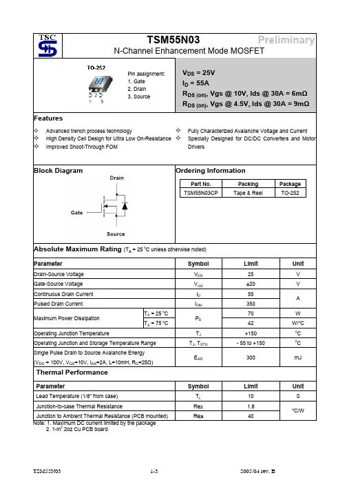
TSM25N0325V N-Channel MOSFETTO-252Features● Advance Trench Process Technology● High Density Cell Design for Ultra Low On-resistanceApplication● Load Switch● Dc-DC Converters and Motors DriversOrdering InformationPart No.PackagePackingTSM25N03CP ROTO-2522.5Kpcs / 13” ReelAbsolute Maximum Rating (Ta = 25o C unless otherwise noted)ParameterSymbolLimitUnitDrain-Source Voltage V DS 25 V Gate-Source VoltageV GS ±20 V Continuous Drain Current, V GS @4.5V. I D 25 A Pulsed Drain Current, V GS @4.5VI DM100 A Continuous Source Current (Diode Conduction)a,bI S 20 A Single Pulse Drain to Source Avalanche Energy (V DD = 100V, V GS =10V, I AS =2A, L=10mH, R G =25Ω) EAS 45 mJ Ta = 25oC 60 Maximum Power Dissipation Ta = 70o CP D 23 WOperating Junction TemperatureT J +150 o C Operating Junction and Storage Temperature RangeT J , T STG-55 to +150oCThermal PerformanceParameterSymbol Limit Unit Lead Temperature (1/8” from case) T L10SJunction to Case Thermal ResistanceR ӨJC 1.8 o C/W Junction to Ambient Thermal Resistance (PCB mounted) R ӨJA40oC/WNotes:a. Maximum DC current limited by the packageb. Surface Mounted on 1” x 1” FR4 Board, t ≤ 10 sec.PRODUCT SUMMARY V DS (V) R DS(on)(m Ω)I D (A)14 @ V GS = 10V 25 2519 @ V GS = 4.5V25Pin Definition: 1. Gate 2. Drain 3. SourceBlock DiagramN-Channel MOSFETTSM25N0325V N-Channel MOSFETElectrical Specifications (Ta = 25o C unless otherwise noted)ParameterConditionsSymbolMinTypMaxUnitStaticDrain-Source Breakdown Voltage V GS = 0V, I D = 250uA BV DSS 25 -- -- V Gate Threshold Voltage V DS = V GS , I D = 250uA V GS(TH) 1.0 1.9 3.0 V Gate Body LeakageV GS = ±20V, V DS = 0V I GSS -- -- ±100 nA Zero Gate Voltage Drain Current V DS = 25V, V GS = 0V I DSS -- -- 1.0 uA On-State Drain CurrentV DS ≥5V, V GS = 10V I D(ON) 25 -- -- A V GS = 4.5V, I D = 25A -- 14.5 19 Drain-Source On-State Resistance V GS = 10V, I D = 25A R DS(ON) -- 9.5 14 m Ω Forward Transconductance V DS = 15V, I D = 15A g fs -- 12 -- S Diode Forward Voltage I S = 20A, V GS = 0VV SD -- 0.87 1.5 V Dynamic bTotal Gate Charge Q g -- 14.726 Gate-Source Charge Q gs -- 2.5 -- Gate-Drain Charge V DS = 15V, I D = 25A, V GS = 10VQ gd -- 3 -- nCInput Capacitance C iss -- 921 -- Output CapacitanceC oss -- 208.7 -- Reverse Transfer Capacitance V DS = 15V, V GS = 0V, f = 1.0MHzC rss--108.2 -- pFSwitching cTurn-On Delay Time t d(on) -- 20.2 -- Turn-On Rise Time t r -- 5.9 -- Turn-Off Delay Timet d(off)-- 49.5 -- Turn-Off Fall Time V DD = 15V, R L = 15Ω, I D = 1A, V GEN = 10V, R G = 16Ωt f --16.7--nSNotes:a. pulse test: PW ≤300µS, duty cycle ≤2%b. For DESIGN AID ONLY, not subject to production testing.b. Switching time is essentially independent of operating temperature.TSM25N0325V N-Channel MOSFETElectrical Characteristics Curve (Ta = 25o C, unless otherwise noted)Output CharacteristicsTransfer CharacteristicsOn-Resistance vs. Drain CurrentGate ChargeOn-Resistance vs. Junction TemperatureSource-Drain Diode Forward VoltageTSM25N0325V N-Channel MOSFETElectrical Characteristics Curve (Ta = 25o C, unless otherwise noted)On-Resistance vs. Gate-Source VoltageThreshold VoltageMaximum Safe Operating AreaNormalized Thermal Transient Impedance, Junction-to-AmbientTSM25N0325V N-Channel MOSFETSOT-252 Mechanical DrawingMarking DiagramY = Year Code M = Month Code(A =Jan, B =Feb, C =Mar, D =Apl, E =May, F =Jun, G =Jul, H =Aug, I =Sep, J =Oct, K =Nov, L =Dec) L = Lot CodeTO-252 DIMENSIONMILLIMETERS INCHES DIM MINMAXMINMAXA 2.3BSC 0.09BSC A1 4.6BSC 0.18BSCB 6.80 7.20 0.268 0.283C 5.40 5.60 0.213 0.220D 6.40 6.65 0.252 0.262E 2.20 2.40 0.087 0.094F 0.00 0.20 0.000 0.008G 5.20 5.40 0.205 0.213 G1 0.75 0.85 0.030 0.033 G2 0.55 0.65 0.022 0.026H 0.35 0.65 0.014 0.026I 0.90 1.50 0.035 0.059J 2.20 2.80 0.087 0.110K 0.50 1.10 0.020 0.043L 0.90 1.50 0.035 0.059 M1.301.700.0510.67TSM25N0325V N-Channel MOSFETNoticeSpecifications of the products displayed herein are subject to change without notice. TSC or anyone on its behalf, assumes no responsibility or liability for any errors or inaccuracies.Information contained herein is intended to provide a product description only. No license, express or implied, to any intellectual property rights is granted by this document. Except as provided in TSC’s terms and conditions of sale for such products, TSC assumes no liability whatsoever, and disclaims any express or implied warranty, relating to sale and/or use of TSC products including liability or warranties relating to fitness for a particular purpose, merchantability, or infringement of any patent, copyright, or other intellectual property right.The products shown herein are not designed for use in medical, life-saving, or life-sustaining applications. Customers using or selling these products for use in such applications do so at their own risk and agree to fully indemnify TSC for any damages resulting from such improper use or sale.。