用于 LTE 的 实时信令分析仪 - JDSU
- 格式:pdf
- 大小:311.89 KB
- 文档页数:4
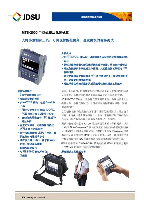
JDSU(安科特纳)MTS5100系列OTDR JDSU(安科特纳)MTS5100系列OTDR是先进的模块化测试仪,可以完成高精度的FTTx测试。
独特的JDSU MTS-5100具备多种可插拔的测试模块,提供完整的解决方案,可以提供OTDR、光功率计、光电话等一体化综合型现场仪表。
功能强大,简单易用,具有极高的性价比。
仪表外缘采用防震设计,特别适合在野外的网络安装、维护。
MTS-5100平台具有各种可现场更换的模块,这些模块包括多模模块,适用于短距离或FTTx (SRe) 、中等距离(DR)、长距离(HD) 、超长距离(VHD) 及1625nm的OTDR 模块,以及可见光故障定位器(红光光源),光源和光功率计、光话机子模块。
JDSU的光时域反射仪(OTDR)和损耗测试模块结构紧凑,构成了功能强大MTS-5100测试家族。
OTDR模块是业内最快的,同时也是市场上任何用于现场使用的OTDR 中能够提供最高性能的解决方案。
OTDR与LTS 模块可以为FTTx光纤网络的安装与维护提供高精度的、高性价比的、高可靠性的测试。
特点:具备两个测试模块槽位。
使全范围的OTDR模块和光损耗测试模块(OLTS)能够同时覆盖光纤线路测量的每一种应用。
单模模块与多模模块可同时插入仪表,无需更换。
在阳光直射下,具有更高的可视度。
这个全新的高可视度屏幕能够在任何光线条件下使用。
从LAN(1.5 m 事件盲区) 到超长应用(44 dB 动态范围)。
高性能测试( 0.1 秒实时扫描时间,具有高至128,000 个采样点)。
提供最大的便携能力(3.5kg) 以及高至16 小时的电池工作时间。
一套完整的PC 软件可以增强MTSe 上的OTDR 报告能力。
Acterna MTSe OTDR 是当前市场上速度最快的、更可靠的、精确的OTDR MTS-5100具有多种功能的测试模块,组合在一起时,全自动和快速测试的特点,可以为执行FTTx光纤网络的开通与故障定位节约可观的时间。


龙源期刊网 无线网络测试解决方案提供商捷迪讯(JDSU)公司作者:来源:《移动通信》2011年第19期捷迪讯(JDSU)公司是全球通信及光学领域的领先企业,总部设在美国加利福尼亚州,在全球30多个国家设有代表处,在我国的北京、苏州、深圳设有分支机构。
JDSU公司近年来为运营商、设备商的2G/3G/4G移动网络提供了先进的端到端的测试解决方案,获得了用户广泛认可。
201 1中国国际信息通信展期间,本刊记者在展会现场与捷迪讯公司北亚区总经理邓伟安先生等进行了简单座谈。
据邓伟安先生介绍,J DSU公司的测试解决方案能够提供对GSM、GPRS、EDGE、UMTS、HSPA、TD-SCDMA、CDMA2000、EVDO、TD-LTE、FDD-LTE、WiMAX等技术的全面支持,其中包括无线网络覆盖质量测试和优化、接入网和核心网信令测试和故障定位、KPl分析以及7×24的实时监控和保障、基站现场开通及维护测量验证等的测试工具及监测系统。
JDSU公司的路测解决方案可对FDD-LTE@TD-LTE网络进行优化和故障诊断,提供扫频仪和手机方案的测量。
JDSU的实时信号分析仪(SART)解决方案可用于测试不同场景下的LTE 语音通话性能,包括漫游和网络互连、自组网络、切换及重新定位,能为网络整体过渡到LTE 提供端到端支持的解决方案。
JD745A基站综合仪可用于各种基站的研发、调测、安装和维护、天馈测试和频谱干扰测试,是一种较理想的现场测试工具,可完成维护人员全部的日常测试。
2011年3月,香港移动通讯有限公司(CSL)选择JDSU公司的解决方案支援该公司在香港的LTE/DC—HSPA+网络部署。
根据合约,JDSU将对CSL的现有客户通话性能监察平台进行扩充升级,用以支援LTE技术,令CSL能为客户提供全球领先的移动宽频服务。
2011年9月,由多业务论坛(MSF)及GSMA共同主办的LTE语音(简称“VoLTE”)互通测试活动在北京中国移动研究中心及德国沃达丰测试与创新中心举行。
捷迪讯JDSU提供卓越的解决方案捷迪讯公司(捷迪讯JDSU)日前在捷迪讯的Different View 上推出了最新视频,讨论在制药行业中日益严重的假冒药品问题,以及捷迪讯JDSU的认证解决方案如何提供帮助制止这种非法活动。
捷迪讯致力于开发和销售各种先进技术以帮助人们体验更加美好的生活。
我们不仅可实现快速优质的通讯并确保财务交易的安全性,还可提供性能可靠的消费电子产品、绿色能源、出色品牌以及其它多种卓越解决方案。
所有这些卓越解决方案都是通过我们的三大业务部门鼎力提供:通讯测试及测量部门、通讯及商业光产品部门以及先进光技术部门。
捷迪讯JDSU公司透露其8500系列40G DP-QPSK(双偏振四相相移键控调制)Transponder 相干模块现开始样品出货。
该产品采用了ClariPhy通信公司的相干处理技术。
Oclaro的MI 5000XM 40G相干模块也采用了ClariPhy的类似技术。
捷迪讯JDSU 8500系列Transponder集成了捷迪讯JDSU的几个光学器件,包括一个相干接收器(intradyne coherent receiver)、一个可调谐激光器和一个铌酸锂调制器。
捷迪讯JDSU称该模块可支持3000公里以上的无补偿光纤传输。
捷迪讯JDSU传输模块营销副总裁Tom Fawcett表示:“在ClariPhy的单芯片相干技术及其团队的支持下,我们得以成功推出8500系列Transponder,这是我们的客户一直期待的成本效率和功效都更高的40G相干传输的升级产品。
我们相信该产品的出货将是40G 相干传输大规模部署过程中的一个转折点。
”ClariPhy首席执行官兼总裁Nariman Yousefi表示:“通过推出一款采用了自身研发的关键光学器件且成本效率和功效都更高的Transponder,捷迪讯JDSU正加速40G相干传输的部署。
我们很荣幸能向捷迪讯JDSU提供领先的SoC解决方案,支持捷迪讯JDSU在该领域的发展。

龙源期刊网
JDSU数字测试和监测解决方案
作者:JDSU
来源:《通信产业报》2008年第09期
在此次的展会上,JDSU将带您进行全新方式欣赏数字业务。
JDSU的突破性数字测试和监测解决方案让你能看到更多!
DSAM-6000全合一三重播放现场测试仪提供最准确的测试结果以及JDSU特有的功能。
这些包括:
数字质量指数TM(DQI)—显示难以捕捉间歇发生的数字问题验证结果——简洁明了。
QAM侵入TM-能够在不中断业务的前提下实时查看QAM数字信号下的异常——这是频谱分析仪所看不到的。
VoIPCheckTM—可与大量DOCSIS测试选件组合使用,显示数据包的分段统计——丢
包,包抖动,时延,也包括R值和MOS等呼叫质量。
StealthSweepTM—业界验证过的无干扰正反向扫频。
DSAM-6000与现有的SDA扫频设备兼容,无需购置新的头端设备。
使用JDSU的高效率解决方案就像拥有了X光透视功能,通过远端数据接入TechCompleteTPP和家庭网络验证(HomeCertification)在现场定位故障,可以将工作效率提高30%以上。
同时比较PathTrak现场查看系统与本地频谱可以快速分析回传通道的侵入问题。
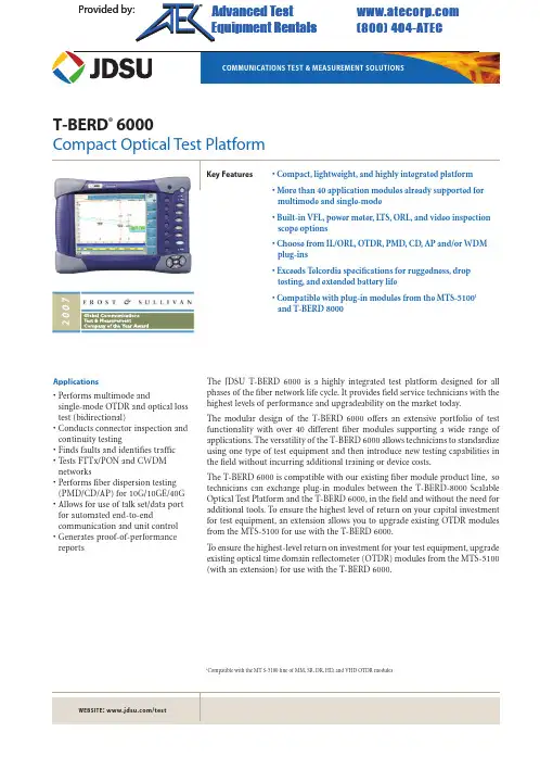
T-BERD ®6000Compact Optical Test Platform Key Features •Compact,lightweight,and highly integrated platform•More than 40 application modules already supported formultimode and single-mode•Built-in VFL,power meter,LTS,ORL,and video inspectionscope options •Choose from IL/ORL,OTDR,PMD,CD,AP and/or WDMplug-ins•Exceeds Telcordia specifications for ruggedness,droptesting,and extended battery life•Compatible with plug-in modules from the MTS-51001and T-BERD 8000The JDSU T-BERD 6000 is a highly integrated test platform designed for all phases of the fiber network life cycle.It provides field service technicians with the highest levels of performance and upgradeability on the market today.The modular design of the T-BERD 6000 offers an extensive portfolio of test functionality with over 40 different fiber modules supporting a wide range of applications.The versatility of the T-BERD 6000 allows technicians to standardize using one type of test equipment and then introduce new testing capabilities in the field without incurring additional training or device costs.The T-BERD 6000 is compatible with our existing fiber module product line,so technicians can exchange plug-in modules between the T-BERD-8000 Scalable Optical Test Platform and the T-BERD 6000,in the field and without the need for additional tools.To ensure the highest level of return on your capital investment for test equipment,an extension allows you to upgrade existing OTDR modules from the MTS-5100 for use with the T-BERD 6000.To ensure the highest-level return on investment for your test equipment,upgradeexisting optical time domain reflectometer (OTDR) modules from the MTS-5100(with an extension) for use with the T-BERD 6000.Compatible with the M T S-5100 line of MM,SR,DR,HD,and VHD OTDR modulesApplications•Performs multimode andsingle-mode OTDR and optical losstest (bidirectional)•Conducts connector inspection andcontinuity testing•Finds faults and identifies traffic•Tests FTTx/PON and CWDMnetworks•Performs fiber dispersion testing(PMD/CD/AP) for 10G/10GE/40G•Allows for use of talk set/data portfor automated end-to-endcommunication and unit control•Generates proof-of-performancereports P r o vided b vided by y : com (800)40404-A -ATE TEC CAd Advanced vanced T Test est E quipment Rentals ®Microphone(4) Molded Bumpers(7) Soft Keys(Context Sensitive)(5) Direct Access Keysand Start/StopNavigation Key PadRemovable High-CapacityLi Ion Battery (8-hour battery life)T-BERD 6000 Front Panel Ideal for Field TestingThe T-BERD 6000 is a highly integrated platform with a single module slot and the option to extend internal memory up to 1 gigabyte.The platform features an intuitive graphical user interface (GUI) shown on a large 8.4 inch transreflective color display (with an optional touchscreen) to improve viewing under any condition.The high capacity Lithium ion battery adds extended life.Other features include an optional video inspection scope (via USB port),and optional built-in optical test functions,such as a visual fault locator (VFL),power meter,optical return loss (ORL) and loss test sets (LTS).The T-BERD 6000 also has a built-in optical talk set option for communicating and controlling remote units along the fiber,and it can transfer data fast using the USB or Ethernet port.8.4 in Indoor/Outdoor TFT Color Display,Touchscreen ConfigurablePower Meter Visual Fault Locator AC InputHeadsetOptical Talk Set/Light Source/ORL High-SpeedEthernet Port (2) USB Ports (Video Inspection Scope Option)T-BERD 6000 Top SideOverview of Fiber Optic Applications Compact and Highly IntegratedThe versatility of the T-BERD 6000 allows it to address premises to long-haul network s comprising new technologies,such as various fiber network s (FTTx),remote optical add/drop multiplexers (ROADMs),and 40 G.–Built-in VFL,laser source power meter,LTS,talk set/data,and video inspection scope options (simultaneously)–Bidirectional insertion loss (IL) and ORL capabilities combined in one module –OTDR and chromatic dispersion (CD) capabilities combined in one module –Polarization mode dispersion (PMD),wave division multiplexing (WDM),and attenuation profile (AP) capabilities combined in one module –PMD,CD,and AP capabilities combined in one module Wide Range of Test Applications–10 GigE local area network (LAN) qualification Solution:T-BERD 6000 with the unique universal SRL 850/1300/1310/1550/1625 nmOTDR Module–End-to-end connectivity on point-to-point network s,including sectionalized testing on a passive optical network (PON) (without a splitter)Solution:T-BERD 6000 with the VSRe,SRe,MR OTDR module at 1310/1550 nm –End-to-end connectivity on PONs,including splitter qualification Solution:T-BERD 6000 with the MR,LR,or VLR at 1310/1490/1550 nm OTDR moduleAdd optional VFL,power meter,and video inspection scope–In-service maintenance and troubleshooting without service disruption Solution:T-BERD 6000 with the filtered LR OTDR module at 1625 nm –End-to-end connectivity and fiber splice qualificationSolution:T-BERD 6000 with the MR,LR,or VLR at 1310/1550/1625 nm OTDR module Add optional VFL,power meter,and video inspection scope LAN/WAN Premises Metro/Core NetworksFTTx/Access Networks4–End-to-end connectivity and fiber splice qualification Solution:T-BERD 6000 with the UHD OTDR module at 1310/1550/1625 nmDynamic range of 50 dB available at 1550 nm–Characterize fiber in high-speed transmission systems for loss/dispersion Solution:T-BERD 6000 with the PMD/CD/AP ,ODTR,and OFI module–Characterize fiber and prove suitability to carry multiple channels (water peak)Solution:T-BERD 6000 with the VLR OTDR module at 1383 nmAdd the combined PMD/WDM/SA or CDWM OTDR module–New technologies developed in the futureSolution:T-BERD 6000 with the new JDSU field-upgradeable application module 10G/40G Fiber Characterization CWDM/DWDM Modular PlatformUltralong-Haul Networks Modular designOTDR and IL/ORL TestingA Wide Range of OTDR ModulesThe JDSU OTDR plug-in module family provides a wide range of high-performance OTDRs.Over 40 field-interchangeable modules are compatible withthe T-BERD 6000 for testing and troubleshooting any multimode or single-mode network.The OTDR family includes six lines of OTDRs featuring:–New wavelengths to cover 1383 nm (CWDM) and 1490 nm (FTTx) –Highest dynamic range up to 50 dB–Shortest dead zones down to 0.5 m in multimode and 0.8 m in singlemode–Fastest scan speed at 0.1 s in real-time modeFrom Simple Fault Locator to Expert OTDR…The fault locator boosts productivity in the field by providing:The expert mode offers high-level trace analysis possibilities,mak ing yourT-BERD 6000 platform a powerful instrument for commissioning and trouble-shooting by offering:-Manual settings (pulse,acquisition time,resolution,distance range)-Manual addition and deletion of events-Manual slopes,splices,and reflectances measurementIndustry leader for dynamicrange with 50 dB Revolutionary 50 cm dead zone automationloss,and ORL measurementsFigure 2 Fault locator modeIdeal for End-to-End CommissioningOTDR bidirectional testing is required to obtain true and accurate splice loss readings.JDSU has developed an innovative automatic bidirectional analysis function that is integrated directly into the T-BERD 6000 platform,saving at least 50 percent of the time required for traditional bidirectional analysis.–Offers communication between two units via the link under test to set up the same optimized acquisition parameters–Displays and saves automatic acquisitions in both directions on both units –Eliminates operator errorUnique to the market:Fully automatic bidirectionalacquisition and analysisLocalT-BERD 6000T-BERD 6000Remote Figure 3Bidirectional OTDR measurement CWDM OTDR ModulesThe CWDM OTDR module allows in-service OTDR measurements at International Telecommunications Union (ITU-T) G.694.2 CWDM wavelengths.This solution was developed to help network operators and dark fiber providers characterize,maintain,and troubleshoot CWDM systems from short- to medium-haul fiber networks.Figure 4 Qualification of a CWDM networkFTTx/PON In-Service ModulesTo avoid interrupting customer traffic (in-service testing) of B/G/E-PON networks the filtered OTDR module performs an out-of-band test using 1625 nm wavelength.Insertion Loss and Optical Return Loss Testing–Measures bidirectional IL,ORL,and fiber length –Offers one-button automated testing –Choose three wavelengths from 1310,1490,1550,and 1625 nm –Compatible with the OFI-2000 Multifunction Loss Test SetCD,PMD,AP,and WDM TestingThe T-BERD 6000 enables CD and PMD measurements to identify fiber viability for very high-speed transmission systems.It also enables WDM and AP tests to validate the link compatibility with DWDM system implementation.Polarization Mode Dispersion Testing–Fast and accurately measures PMD delay,PMD coefficient,andsecond-order values–Offers high dynamic range (up to 65 dB) dedicated for metropolitan,long haul, and very long haul fiber optic links–Offers shock- and vibration-proof design (with no moving parts)–Allows for measurement through multiple amplifiers–Provides statistics and long-term monitoringChromatic Dispersion Testing - OTDR-Based Method–Requires access to only one end of the fiber–Offers dynamic range (up to 120 km) dedicated for any metropolitan fiber optic links–Includes acquisition points around 1310,1480,1550,and 1625 nm for accurate CD from 1260 to 1650 nm–Integrates a four-wavelength OTDR and light source–Provides sectional analysis capability for troubleshooting–Offers shock- and vibration-proof design (with no moving parts)9T-BERD 6000 COMPACT OPTICAL TEST PLATFORMChromatic Dispersion Testing - Phase-Shift Method–Offers high dynamic range (up to 55 dB) dedicated for metropolitan,long haul, and very long haul fiber optic links–Provides full wavelength range characterization (1260 to 1640 nm)–Allows for measurement through multiple amplifiers–Offers shock- and vibration-proof design (with no moving parts)Attenuation Profile Testing–Provides total loss and dB/km values for full band testing (1260 to 1640 nm)–Allows CDWM and dense wavelength division multiplexing (DWDM) transmission band characterization–Provides water peak (1383 nm area) characterization–Offers shock- and vibration-proof design (with no moving parts)–Combined with WDM and PMD functions or with CD and PMD functionsDWDM Maintenance Testing–Measures channel level,power,and wavelength in the S,C,and L bands–Provides the most compact DWDM test solution that measures optical signal-to-noise ratio (OSNR)–Tests wavelengths from 1260 to 1640 nm or 1485 to 1640 nm–Offers high wavelength accuracy–Provides statistics and long-term monitoring–Offers shock- and vibration-proof design (with no moving parts)10Generate cable acceptance reportsReport single test resultsP rofessional acceptance test reports OTDR trace report Options and AccessoriesGreater Productivity with CommunicationsWith limited telephone line and cell phone coverage during fiber testing,the T-BERD 6000 offers a built-in optical talk set option for permanent communication between test technicians.Near- and far-end technicians can communicate with each other,avoiding many of the testing mistakes that can prove costly if another truck roll is required to fix a problem.For bidirectional testing that requires both the near- and far-end units to acquire data,the Data mode on the optional talk set synchronizes data acquisition for both units during OTDR testing and retrieves test results for pass/fail analysis.–Provides 45 dB optical talk set–Provides file transfer capability through the fiber–Provides remote control of the far-end unit–Provides a talk set compatible with the OFI-2000 and with the OTS-55 Optical Talk Set stand-alone unitEffective Test Report GenerationTransfer data and generate comprehensive reports using JDSU FiberTrace and FiberCable analysis software.–Generate proof-of-performance reports with a high degree of customization –Create dedicated tables for each test result (OTDR,CD,PMD,and ORL)–Provides pass/fail indicators for quick analysis of problem areas –Identifies macro bends and provides fault report summary11Comprehensive Line of AccessoriesA wide range of available accessories provide technicians with everything needed to benefit from the complete testing capabilities of the of the T-BERD 6000.Join the T-BERD Family of Optical Test SolutionsBased on the same graphical user interface (GUI) and file formats,the T-BERD 6000,T-BERD 6000A,and the T-BERD 8000 form a family of solutions for high-performance field testing.In addition,the fiber application plug-in modules are field interchangeable with the T-BERD 6000,T-BERD 6000A,and the T-BERD 8000,ensuring maximum flexibility and investment protection.The T-BERD 6000 can house one fiber application plug-in module.The T-BERD 6000A with the Multi-Services Application Module (MSAM) offers Ethernet and SONET/SDH testing at line rates from 10 Mb/s up to 10 Gb/s,as well as the ability to verify and troubleshoot higher-layer IP video,Layer 4 UDP/PCP ,FTP ,and HTTP .The T-BERD 8000 can house multiple modules simultaneously,enabling the perform-ance of almost any combination of network test functions in a single unit.In addition,the T-BERD 8000 also offers:–DWDM turn-up testing–Dual-port optical spectrum analysis–DWDM channel isolation for BERT analysis –E1/T1 to 10G BERT analysis–10/100/1000/1G/10G Ethernet testingT-BERD 6000 LITE Compact OTDR T-BERD 6000Compact Optical Test Platform T-BERD 6000ACompact Network Test Platform T-BERD 8000Scalable Optical Test PlatformThe T-BERD 6000 with the optional mouse,keyboard,battery,headset,AC/DC adapter charger,and video inspection scopeT-BERD 8000 field-scalable optical test platformView clean and dirty fiber end faces with the connector inspection option.Test & Measurement Regional SalesProduct specifications and descriptions in this document subject to change without notice.© 2008 JDS Uniphase Corporation November 200830162566 000 1108 TB6000.DS.FOP .TM.AESpecifications for Typical 25°CDisplayTFT color,8.4 in LCD,800 x 600,high-visibility (standard)Touchscreen,TFT color,8.4 in LCD,800 x 600,high-visibility (optional)Storage and I/O Interfaces Internal memory 1000 test results Extended memory (optional)Minimum 1 GB (optional)2x USB V1.1,1x RJ45 Ethernet Power Supply Battery type Standard removable Li-ion batteries AC/DC adapter Input 100–240 V,50–60 Hz,Output 19 V DC/3.1 AOperation time Up to 11 hrs with standard display,Telcordia GR-196-CORESize and WeightMainframe with one plug-in module and battery (L x H x W)285 x 195 x 93 mm(11.2 x 7.7 x 3.7 in)Mainframe only (without battery and module) 2.4 kg (5.3 lb)Mainframe (with one plug-in module and battery) 3.4 kg (7.5 lb)Environmental SpecificationsOperating temperature range on mains (no options)–20 to +50°C (–4 to 122°F)Operating temperature range (all options)0 to +40°C(32 to 104°F)Storage temperature range –20 to +60°C (–4 to 140°F)Humidity,non-condensing 95%Base Unit Optical Interfaces (optional)Power Meter Power level+10 to –60 dBm Calibrated wavelengths 850,1310,and 1550 nm Connector type Universal push/pull (UPP)Talkset Wavelength 1550 nm ±20 nmDynamic range 45 dBFunction With data/file transferLaser safety Class 1M laser Connector typeField interchangeableOptical Return Loss Selectable wavelength 1310 / 1550 nm Measurement range 0 dB to 45 dBMeasurement uncertainty ±1 dB Display resolution0.01 dBVisual Fault Locator Wavelength 635 nm ±15 nm Output power level <1 mW Laser safety Class 2 laser Connector type Universal push/pull (UPP)Continuous Wave Light Source Wavelengths (selection)1310,1550,and 1625 nm Output power level –3.5 dBm Stability in 15 min ±0.02 dB Stability in 8 hrs ±0.2 dB Laser safety Class 1M laser Connector type Field interchangeable Video Inspection Scope (via USB)Magnification 250X and 400X,through the USB portBase InstrumentT-BERD 6000 platform with high-visibilitycolor display and battery packTB6000T-BERD 6000 platform with high-visibility touchscreen color display and battery pack TB6000T Extended memory (1 GB)E60EXTMEM VFL with 2.5 mm UPP E80VFL Optical talk set E80TS Optical power meter with UPP connector (2.5 mm provided as standard)E80PM Optical loss test set 1550/1625 nm with talk set E8029LTSTS Optical loss test set with talk set (1310/1550/1625 nm)E8036LTSTS Combined LTS and ORL with talk set(1310/1550 nm )E8026LTSTSORL Bidirectional OTDR acquisitionoption for single-mode moduleE80bidir Quick capture video microscope,200x/400x with USB converterEFSCOPE400AccessoriesCigarette lighter power adapterE80lighter Additional Li-Ion rechargeable batteryE60LiIon Wrap around carrying case for 6000 platformESCASE5Application SoftwareOptical FiberTrace software (for post-analysis)EOFS100Optical FiberCable software(for acceptance report generation)EOFS200Optical connectors for the loss test set and talk set options (connector must be of the same type)Field replaceable connectors:EUNIPCFC,EUNIPCSC,EUNIPCST,EUNIPCDIN,EUNIPCLC,EUNIAPCFC,EUNIAPCSC,EUNIAPCST,EUNIAPCDIN,EUNIAPCLCPlease refer to the separate module datasheets for detailed specifications.。

WEBSITE: 22008923r000Capturing and Analyzing PacketsBefore testingBefore capturing packets, consider the following:What is captured? All received traffic (test traffic, control plane traffic, and live traffic) that satisfies the user-specified filter criteria can be captured on all supported interfaces. All transmitted traffic (test traffic, control plane traffic, and life traffic) that satisfies the user-specified capture criteria can be captured for all supported interfaces up to 1 Gigabit Ethernet . When capturing transmitted traffic from a 10 Gigabit Ethernet interface, only control plane traffic is captured . Ethernet frames ranging from 4 to 10000 bytes long can be captured, but the 4 byte Ethernet FCS is not stored in the capture buffer.How much can be stored in the buffer? You can specifying a buffer size ranging from 1 MB to 256 MB. You can also indicate that the instrument should stop capturing packets when the buffer is full, or overwrite the oldest packets in the buffer with new captured packets in 1 MB incre-ments.Why use packet slicing? You can tell the instrument to capture only the first 64 or 128 bytes of each packet, which allows you to analyze the most important data (carried in the packet headers), and to capture and store more packets in the buffer.Configuring the testBefore capturing packets, you specify filter settings (for received packets), and capture settings. When capturing packets in Monitor or Terminate mode, you must use Port 1 for your test. If you are capturing packets in Dual Through mode, both ports can be used.Configuring a capture for a large buffer (for example, 256 MB), with small packets (for example, 46 byte ping packets), will take a long time to fill the buffer. Configuring the capture for a small buffer with large packets will fill the buffer quickly.2Capturing and Analyzing Packets WEBSITE: Step 1On the Main screen, use the Test menu to select the application for the interface you are testing.Step 2Select the Capture tool bar, then enable the capture feature.Step 3Select the Setup soft key, and then do the following:a Select the Filters tab, and then do one of the following:- If you launched a layer 2 application, select Ethernet , andthen specify the settings that capture the received traffic thatyou want to analyze.- If you launched a layer 3 or layer 4 application, and youwant to specify basic filter information, select Basic , andthen specify the Traffic Type and the Address Type carriedin the received traffic you want to capture.- If you launched a layer 3 or layer 4 application, and youwant to specify detailed filter information, select Basic , andthen set the filter mode to Detailed .Use the Ethernet , IP , and TCP/UDP selections in the paneon the left to display the filter settings for your particular test,and t hen s pecify t he s ettings t hat c apture t he r eceived t rafficthat you want to analyze.b Select the Capture tab, then specify the following settings:Setting ParameterCapture buffer size(MB)Specify a size ranging from 1 to 256 MB in a 1 MB increment. The default buffer size is 16 MB.Capture frame slic-ing If you want to capture the first 64 or 128 bytes of each frame (and ignore the rest of the frame), select 64 or128; otherwise, select None.If you select None (the default), the entire frame is cap-tured.When capture buf-fer is filled If you want to overwrite the oldest packets with newpackets when the buffer becomes full, selectWrap Capture ; otherwise, select Stop Capture .Include frames from Traffic tabIf you want to capture transmitted frames (the trafficload which is specified on the Traffic tab), select Yes .Capturing and Analyzing Packets3 Step 4Select the Results soft key to return to the Main screen.Connecting to the circuitStep 1Using a fibre scope, inspect the cables and components that you intend to use to connect your instrument to the circuit. Ifnecessary, clean them.Step 2Verify that your instruments are connected properly for the test. When capturing packets, you can connect to the circuit using an end-to-end configuration or a loopback configuration.Starting the testStep 1Do the following:–If you are testing on an optical circuit, turn the laser on.–If you are capturing transmitted or looped back traffic, select Start Traffic.Step 2Select the Capture toolbar, and then do the following:a Select Start Capture. A message appears in the messagebar indicating that the capture has started, and the actionkey states Capture Started.b If you want to capture packets that shows how the traffic isimpacted by various events, use the buttons on theActions, Errors, and Fault Signaling tool bars to insert theevents into the transmitted traffic stream.Step 3If you want to stop capturing packets before the buffer is full (for example, after the instrument has transmitted and received acertain number of frames), select the Capture Started actionkey. The action key turns grey, and a message appears in themessage bar indicating that the capture is complete.WEBSITE: 4Capturing and Analyzing PacketsSaving or exporting captured packetsYou can safe captured packets in the buffer to the internal USB drive, or export them to an external USB drive. You can save the entire buffer, or just part of the buffer. You can also optionally compress the data. Many factors contribute to the length of time it takes to save a captured file, but the key factors are the packet density and the capture size.Step 1On the Main screen, select Save Capture Buffer, then select a location, and then specify the other save settings (file name,whether to compress the file, and whether to launch Wireshareafter saving.Step 2Select the Save button at the bottom of the dialog box.A dialog box appears above the Main screen showing thepercentage of the buffer that has been saved. When buffer issaved, the box closes. If you indicated that you wanted Wire-shark to launch immediately after saving the buffer, the Wire-shark® application appears.Analyzing packets using Wireshark®After saving the packets in the capture buffer (to a PCAP file), you can analyze them in detail on the instrument using the Wireshark® protocol analyzer. Files exceeding 16 MB should not be analyzed on the instrument; large files should be exported for analysis on another device. If you attempt to analyze a file with more than 50,000 packets, the instrument will alert you that the file should be exported for analysis.IMPORTANT: Wireshark® SupportJDSU is distributing Wireshark® on the instrument under the GNUGeneral Public License, version 2. It is not a JDSU product. Fortechnical support, go to the product website at www.wire-.Step 1On the Capture toolbar, select the Wireshark action key. The Open Capture File dialog box appears.Step 2Navigate to and select the file you want to analyze. The Wire-shark® splash screen appears, then a small dialog box appearswhile the application loads the packets in the file you selected. WEBSITE: Capturing and Analyzing Packets 5 WEBSITE: Step 3After the packets are loaded, a screen similar to the one inFigure 3 appears.Step 4Use the controls at the top of the screen to locate and evaluatethe packets. For technical support and product documentation, go to .Analyzing packets using J-MentorIf you want a summarized analysis of the packets, you can use the J-Mentor utility provided on your instrument. The utility is only available for analysis of packets captured on 10/100/10000 Mbps electrical, 100M optical, and 1G optical circuits. J-Mentor can only be used to analyze PCAP files with 50,000 or less packets.Step 1On the Capture toolbar, select the J-Mentor action key. The Open Capture File dialog box appears.Step 2Specify the link bandwidth in Mbps (this is the line rate at whichyou captured the traffic). Then, navigate to and select the file youwant to analyze.Figure 3Sample Wireshark® screen6 Capturing and Analyzing Packets Product specifications and descriptions in this document are subject to change without notice. Wireshark is a registered trademark of the Wireshark Foundation. ©2012 JDS Uniphase Corporation Test and Measurement Regional SalesNORTH AMERICATEL: 1 855 ASK JDSUFAX: +1 301 353 9216LATIN AMERICA TEL:+1 954 688 5660FAX:+2 954 354 4668ASIA PACIFIC TEL:+852 2892 0990FAX:+852 2892 0770EMEA TEL:+49 7121 86 2222FAX:+49 7121 86 Step 3If you want to observe key details for the PCAP file, select GetPCAP Info . This is wise if you suspect the file might exceed the 50000 packet limit for analysis on your instrument. If it does exceed the limit, a message appears instructing you to export the file for analysis.Step 4Select Analyze . The utility immediately checks for the possibility of retransmissions of packets, high bandwidth utilization, top talkers, detection of half duplex ports, and ICMP frames.After analyzing the packets, a summary screen appears indi-cating whether issues were found at layers 1 and 2 (the physical and Ethernet layer), layer 3 (the IP layer), or layer 4 (the TCP/UDP layer). Green indicates everything was fine at a particular layer; Red indicates that there were issues identified at thatlayer.Step 5Use the Details buttons to observe detailed results for eachlayer. For example, if you want to observe a graph of the network utilization, or a list of all IP conversations, press the Detailsbutton for Layer 1 / 2.Step 6Select Exit to return to the Main screen.Related informationUse this Quick Card in conjunction with the Getting Started Manual and Testing Manual that shipped with your instrument.Technical assistanceFor the latest TAC information, go to or contact your local sales office for assistance. Contact information for regional sales headquar-ters is listed at the bottom of this Quick Card.。
JDSU(安科特纳)MTS-6000光时域反射仪MTS-6000是一个结构紧凑的、重量轻的测试平台,设计用于安装与维护光纤网络。
它为现场技术人员提供当今市场上最高级别的性能与可升级能力。
MTS-6000 具有模块化的设计,它能够提供广泛的测试功能,具有40多个不同的光纤模块用于各种类型的应用。
MTS-6000的多功能性使得技术人员能够采用一种类型的测试设备进行标准化的测试,然后可以引入新的现场测试功能而无需增加成本。
由于MTS-6000 与我们目前现有的光纤模块产品系列兼容,技术人员可以现场在MTS-8000多网络测试仪平台与MTS-6000之间更换插拔模块,无需其它的工具。
为了确保您在测试设备上的资金投资获得最高的投资回报率,现有的MTS-5100 的OTDR模块可以(采用扩展)被转化为与MTS-6000 一起使用。
物超所值更高的投资回报率更高的灵活性,能够满足未来的测试需求无可比拟的速度与功能更高的生产率功能特点:结构紧凑,重量轻,高度集成已经可以支持40多个应用模块有IL/ORL、OTDR、PMD、CD 或WDM 插拔模块选择与MTS-5100和MTS-8000的插拔模块兼容带有内置的VFL、功率计、LTS与视频检查显示选件,具有全面的连接检查功能内置的光话机选件用于使用光纤通话话机中的数据模式能够对两个远端单元进行配置、测试与结果采集在严酷度、跌落测试、扩展电池寿命等方面超过Telcordia 的技术指标结构紧凑,高度集成MTS-6000 的多功能性使得它能够解决FTTx/接入网/城域网或者速度为10Gb/s与40Gb/s 的长途/快捷网。
内置VFL、功率计、LTS、话机/数据以及视频检查显微镜选件(同时)在一个模块内具有插入损耗(IL)与光回损(ORL)功能(双向)在一个模块内具有光时域反射计(OTDR)与色散(CD)功能在一个模块内具有极化模式色散(PMD),波分复用(WDM)与光谱衰减(SA)功能宽范围的测试应用对点到点网络执行端到端连接性测试,包括对PON进行分段测试(不带有分束器)解决方案:带有1310/1550 nm 波长的MM、SRe、DR 或HD OTDR 模块的MTS-6000 对PON 的端到端连接性测试,包括分束器性能测试解决方案:带有1310/1490/1550nm波长的VLR OTDR模块的MTS6000及选件VFL功率计与视频检查显微镜在线维护与故障查找而不引起业务中断解决方案:带有1625 nm 波长OTDR 模块的MTS-6000端到端连接性与光纤熔接特性测试解决方案:带有1310/1550/1625 nm 波长的HD 或VLR OTDR 模块的MTS-6000以及选件VFL、功率计与视频检查显微镜端到端连接性与光纤熔接特性测试解决方案:带有1310/1550/1625 nm 波长的UHD OTDR 模块的MTS-60001550 nm 波长的动态范围为50 dB高速传输系统中光纤的损耗/色散特性测试解决方案:带有PMD、CD/ODTR 或OFI 模块的MTS-6000光纤特性测试并验证其承载多个信道的适用性(水峰)解决方案:带有1383nm波长的VLR OTDR模块的MTS-6000采用组合的PMD/WDM/SA 模块未来所开发的新技术解决方案:具有JDSU 新应用模块的MTS-6000应用:JDSU 已经开发出宽范围的现场可替换OTDR 模块,适用于任何网络类型上的任何应用。
以太网测试仪一、测试原理发送出仪表专用的以太网负载数据,通过检验接收的数据情况检测被测电路的表现(如正常情况下和超大负荷情况下的表现)。
测试该电路的带宽(例如吞吐量),以及处理业务的性能指标如何(例如时延)。
二、仪表介绍现测试北京移动数据业务设备为美国JDSU公司生产的HST-3000手持测试仪。
1.概述JDSU HST-3000是一款适合于现场使用的结构坚固的模块化测试平台,配备了以太网业务接口模块(SIM)就解决了这一对于7层测试的需求。
它具有完整的以太网测试特性,能够测试高达1Gbit/s的电口与光口链路。
HST-3000支持多个数据流的测试用于验证流量优先级机制,还提供高级监测选件用于更深入的故障排查。
此外,HST-3000的VoIP与IPTV视频选件使得技术人员能够仿真终端客户的感受并客观的测试业务质量。
2.技术指标3.功能说明面板简图(键位说明与板块合一)(1)告警指示灯(2)显示屏幕(3)功能键(4)方向及确认键(5)测试快捷键(6)数字键123 4 5 687(7)仪表调节键(8)电源键4.使用说明4.1 开机/关机12机。
4.2指示灯Sync:此 LED 灯报告链路是否被激活,绿色表示链路处于激活状态。
如果 Sync LED 灯不亮,表示链路当前没有被激活。
Data:此 LED 灯报告探测到帧或包的状态,绿色表示在信息流中探测到帧包或帧。
如果此 Data LED 灯不亮,表示没有探测到帧。
Error:此 LED 灯报告错误状态,红色表示错误。
观察 Summary结果分类确定错误类型。
如果 Error LED 灯不亮,比如所有 Summary结果都正确。
Alarm:当测试和使用 Ethernet SIM时 Alarm LED 灯没用。
LpBk:此 LED 灯指示 HST设备本地环回状态,绿色表示 HST 被设置为环回模式,在远端手动或设备调制。
Batt:此 LED 灯指示电池状态。