魅湃科技M1621521规格书——21.5寸壁挂式电容触摸一体机
- 格式:pdf
- 大小:341.44 KB
- 文档页数:6

DescriptionNEMA L6-20 20A, 250V/AC, 2P-3WDesign features for plug & connector• All nylon construction• EPDM gasket seals cord hole from dust and debris •Back wire terminal clamps for easy secure wiring•Individual wiring compartments with tapered channel for easy insertion of wires•Clear cover over wiring compartments allows easy inspection of wiring terminations• Rating printed on side of device•Largest-in-class grommet size allows for entire cord size rangeDesign features for receptacles• Rugged glass filled nylon body•Clearly marked rating, NEMA configuration and approval listings on receptacle face•One piece brass contacts offer superior performance and minimal heat rise•Back and side wiring terminal clamps for easy, secure wiringDesign features for flanged inlet & outlet• All nylon construction• Mounting holes interchangeable with competitive units • Back wire terminal clamps for easy, secure wiring•Individual wiring compartments with tapered channel for easy insertion of wiresIndustrial gradeL6-20 locking devicesCatalog No.DescriptionAmpsVoltsColorAHL620P Ultra grip plug 20250Black & white AHL620C Ultra grip connector 20250Black & white AHL620RSingle receptacle20250Black AHIGL620R Single receptacle, isolated ground 20250Orange AHL620FO Flanged outlet 20250Black & white AHL620FIFlanged inlet20250Black & whiteAHL620PAHL620RAHL620FOAHL620CCompliances, specifications and availability are subject to change without notice.Project Name:Prepared By:Project Number:Date:Catalog Number:Type:T able 1.NEMA L6-20 Industrial Grade Locking Devices2EATON Technical DataEffective January 2014Industrial gradeL 6-20 locking devicesCatalog No.NEMA L6-20 Plug & ConnectorNEMA Config NEMA L6-20Wiring Type Back wireEnvironmental Specifications Flammability: Meets UL94 requirements; V2 ratedTemperature Rating: -40°C to 60°C (-40°F to 140°F)Electrical Specifications Dielectric Voltage: Twice the device rating + 1000V per UL498Current Interrupting: Yes, at full-rated currentTemperature Rise: Max. 30ºC (86°F) after 50 cycles of overload at 150% of rated current (DC)Mechanical Specifications Terminal Accommodation: #14 - #8 AWGVoltage Ratings: Permanently marked on deviceNEMA L6-20 20A, 250V/AC, 2P-3W Catalog No.NEMA L6-20 Plug & ConnectorNEMA Config NEMA L6-20Outer Shell Nylon Interior Body NylonTerminal Retainer Polycarbonate BladesBrassLine Contacts Bronze, tin plated Terminal Clamps Steel, tin platedTerminal Screws #10-32 brass, zinc plated (neutral screw)Ground Screw #10-32 brassAssembly Screws Steel, nickel plated Gasket/Dust Shield EPDMCord Clamp Screws Steel, nickel plated Cord Clamp NylonCompliances, specifications and availability are subject to change without notice.Plug & ConnectorProject Name:Prepared By:Project Number:Date:Catalog Number:Type:T able 2. SpecificationsT able 3. MaterialsProduct DimensionsFigure 1. AHL620P Figure 2. AHL620C Figure 3. Base Angle3EATON Technical DataEffective January 2014Industrial gradeL 6-20 locking devicesCatalog No.NEMA L6-20 Single ReceptacleNEMA L6-20 Isolated Ground Single ReceptacleNEMA Config NEMA L6-20NEMA L6-20Wiring Type Back & side wireBack & side wireEnvironmental Specifications Flammability: Meets UL94 requirements; V0 ratedTemperature Rating: -40°C to 60°C (-40°F to 140°F)Flammability: Meets UL94 requirements; V0 rated Temperature Rating: -40°C to 60°C (-40°F to 158°F)Electrical Specifications Dielectric Voltage: ≤300V: 2000V, 301-600V: 3000V per UL498Current Interrupting: Yes, at full-rated currentTemperature Rise: Max. 30ºC (86°F) after 250 cycles of overload @ 200% of rated current (DC)Dielectric Voltage: ≤300V: 2000V, 301-600V: 3000V per UL498Current Interrupting: Yes, at full-rated currentTemperature Rise: Max. 30ºC (86°F) after 50 cycles of overload @ 150% of rated current (DC)Mechanical Specifications Terminal Accommodation: #14 - #8 AWGVoltage Ratings: Permanently marked on device Terminal Accommodation: #14 - #8 AWG Voltage Ratings: Permanently marked on deviceNEMA L6-20 20A, 250V/AC, 2P-3W Catalog No.NEMA L6-20 Single ReceptacleNEMA L6-20 Isolated Ground Single ReceptacleNEMA ConfigNEMA L6-20NEMA L6-20Face Glass-filled nylon Glass-filled nylon BaseGlass-filled nylonGlass-filled nylonMounting Strap 0.050" thick steel, zinc plated 0.050" thick steel, zinc plated Line Contacts 0.041" thick brass0.041" thick brassTerminal Screws #10-32 brass, nickel plated (neutral screw)#10-32 brass, nickel plated (neutral screw)Ground Screw#10-32 brass (green)#10-32 brass (green)Terminal Clamps/Plates 0.041" thick brass 0.041" thick brass Ground Contacts 0.041" thick brass0.041" thick brassBack Plate0.041" thick brass, nickel plated 0.041" thick brass, nickel plated Mounting ScrewsSteel, zinc platedSteel, zinc platedSingle ReceptaclesT able 4. SpecificationsT able 5. MaterialsProject Name:Prepared By:Project Number:Date:Catalog Number:Type:Product DimensionsFigure 4. AHL620RCompliances, specifications and availability are subject to change without notice.4EATON Technical DataEffective January 2014Industrial gradeL 6-20 locking devicesCatalog No.NEMA L6-20 Flanged OutletNEMA L6-20 Flanged InletNEMA Config NEMA L6-20NEMA L6-20Wiring Type Back wireBack wireEnvironmental Specifications Flammability: Meets UL94 requirements; V2 ratedTemperature Rating: -40°C to 60°C (-40°F to 140°F)Flammability: Meets UL94 requirements; V2 rated Temperature Rating: -40°C to 60°C (-40°F to 140°F)Electrical Specifications Dielectric Voltage: ≤300V: 2000V, 301-600V: 3000V per UL498Current Interrupting: Yes, at full-rated currentTemperature Rise: Max. 30ºC (86°F) after 50 cycles of overload @ 150% of rated current (DC)Dielectric Voltage: ≤300V: 2000V, 301-600V: 3000V per UL498Current Interrupting: Yes, at full-rated currentTemperature Rise: Max. 30ºC (86°F) @ maximum rated current (DC)Mechanical Specifications Terminal Accommodation: #14 - #8 AWGVoltage Ratings: Permanently marked on deviceTerminal Accommodation: #14 - #8 AWG Voltage Ratings: Permanently marked on deviceNEMA L6-20 20A, 250V/AC, 2P-3W Catalog No.NEMA L6-20 Flanged OutletNEMA L6-20 Flanged InletNEMA Config NEMA L6-20NEMA L6-20Outer Shell Nylon Nylon Interior Body NylonNylonTerminal Retainer Polycarbonate Polycarbonate BladesN/A0.062" thick brass Line Contacts 0.031" thick bronze, tin plated N/ATerminal Clamps Steel, tin platedSteel, tin platedTerminal Screws #10-32 brass, nickel plated (neutral screw)#10-32 brass, nickel plated (neutral screw)Ground Screw #10-32 brass (green)#10-32 brass (green)Assembly Screws Steel, nickel plated Steel, nickel plated Mounting Screws Steel, zinc plated Steel, zinc platedCompliances, specifications and availability are subject to change without notice.Flanged Outlet & InletProject Name:Prepared By:Project Number:Date:Catalog Number:Type:T able 6. SpecificationsT able 7. MaterialsProduct DimensionsFigure 5. AHL620FO Figure 6. AHL620FI Figure 7. T op ViewTechnical DataEffective January 2014Industrial gradeL 6-20 locking devicesElectrical Sector 203 Cooper CirclePeachtree City, GA 30269United States Electrical Sector Canada Operations 5925 McLaughlin RoadMississauga, Ontario, L5R 1B8CanadaEatonCanada.ca Electrical Sector Mexico Operations Carr. Tlalnepantla -Cuautitlan Km 17.8 s/n Col. Villa Jardin esq.Cerrada 8 de MayoCuautitlan, Mexico CP 54800Mexico Eaton.mxEaton is a registered trademark. All other trademarks are property of their respective owners.Eaton1000 Eaton Boulevard Cleveland, OH 44122United States © 2014 EatonAll Rights Reserved Printed in USAPublication No. 125-0076-13January 2014Certifications & CompliancesProject Name:Prepared By:Project Number:Date:Catalog Number:Type:AHL620C •••AHL620R ••••••AHIGL620R •••••AHL620FO ••••AHL620FI•••KEY:cULusUL CSAFed SpecNOMROHSParts are manufactured and designed in accordance with article 4 of the European Union’s RoHS2 directive 2011/65/EUCompliances, specifications and availability are subject to change without notice.。

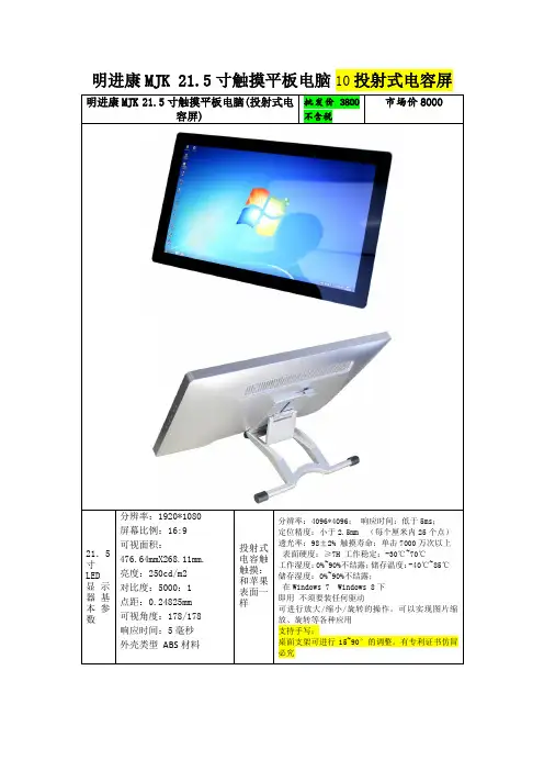
电容一体机23.6英寸电容触摸平板技术规格书(型号:HBY-D236)备注:标配壁挂架,桌面式支架为选配产品;内容如有更改,恕不另行通知一、产品特性1.结构设计:(1)纯平面结构,人体工程学设计,纤巧美观、流线造型、工艺精良;(2)显示、触控、PC系统一体化超薄设计,仅厚43 mm;2.使用效果:(1)采用最新研发的投射式电容屏,完美10点触摸,支持手写及多点手势;(2)触摸速度小于3ms,精确度好,使用简单便捷、易于维护;(3)抗光干扰,确保操作的准确性(强光直射照常使用);3.扩充性好:配置灵活,可扩充安装客户需求的各种功能配件;4.安全性高:铝合金+钣金结构,无锐利边缘,耐磨防腐烤漆工艺,整体防暴设计;5.性能稳定:先进的设计理念,严格的生产工艺,产品品质稳定可靠,故障率低;6.安装简便:通电一键开关机,免除现场安装调试。
二、系统设计三、液晶屏参数四、触摸屏参数五、显示参数 (仅做为触摸显示器部分使用)六、电源参数七、工作环境八、随机附件九、电脑参数十、物理规格屏幕23.6寸(对角线603.6mm)有效显示尺寸525.5×297 mm (16:9)整机尺寸(宽×高×厚)576(宽)×352(高)× 43(厚)mm 包装尺寸(宽×高×厚)635(宽)× 445(高)×140(厚)mm 底架标配壁挂架(净重0.78kg),可选配底座背部壁挂与机器连接的孔100×100 mm位尺寸(长×宽)壁挂螺丝规格M4净重(裸机)触显7.23 kg,一体机7.75kg毛重(包装)9.11 kg十一、整机结构图十二、产品细节图十三、产品款式/产品效果图十四、整机实拍图十五、产品配件图。

南天自助终端产品手册2014年南天自助产品中心产品部2014年4月目录1传统自助终端.....................................................大堂式多功能自助终端......................................Nantian BST-4200/C20..................................Nantian BST-5200 A20..................................穿墙式多功能自助终端......................................Nantian BST-4230/C21..................................壁挂式多功能自助终端......................................Nantian BST-3340/C22.................................. 2自助发卡机.......................................................大堂式发卡机..............................................Nantian BST-5200 B20..................................台式发卡机................................................Nantian BST-3340 H10.................................. 3自助回单机.......................................................大堂式自助回单机..........................................Nantian BST-5810A..................................... 4排队机...........................................................大堂式排队机..............................................Nantian BST-5200/E10.................................. 5其他.............................................................网银终端..................................................Nantian BST-4200/G20..................................预填单机..................................................Nantian BST-5200/B10..................................智能服务终端..............................................Nantian BST-4210 A24..................................存折补登机................................................Nantian BST-1100......................................1传统自助终端1.1大堂式多功能自助终端1.1.1N antian BST-4200/C201.1.1.1效果图1.1.1.2结构尺寸图1.1.1.3功能特点外形新颖:整机采用流线型设计;全注塑面板,美观大方;整机色调协调统一;全功能配置:支持存折补登、银行卡查询及转账等多种传统业务功能的同时,能够播放多媒体广告信息,并支持凭条/账单/发票等多种票据的自助打印功能;可扩展型强:支持激光打印机、发票打印机、条码扫描、非接触式IC卡等多种模块扩展功能;强大的卡业务处理功能:支持磁卡、IC、非接触式IC卡等多种卡片的读写功能;数据安全性高:采用硬件加密键盘;配备读卡器异型卡口及密码键盘防窥式设计,大大提高了用户个人信息的安全性;1.1.1.4标准配置1.1.1.5可扩展配置1.1.2N antian BST-5200 A201.1.2.1效果图1.1.2.2结构尺寸图1.1.2.3功能特点外形新颖:整机采用流线型设计;全注塑面板,美观大方;整机色调协调统一;全功能配置:支持存折补登、银行卡查询及转账等多种传统业务功能的同时,能够播放多媒体广告信息,并支持凭条/账单/发票等多种票据的自助打印功能;可扩展型强:支持激光打印机、发票打印机、条码扫描、非接触式IC卡等多种模块扩展功能;强大的卡业务处理功能:支持磁卡、IC、非接触式IC卡等多种卡片的读写功能;数据安全性高:采用硬件加密键盘;配备读卡器异型卡口及密码键盘防窥式设计,大大提高了用户个人信息的安全性;1.1.2.4标准配置1.1.2.5可扩展配置1.2穿墙式多功能自助终端1.2.1N antian BST-4230/C211.2.1.1效果图1.2.1.2安装尺寸图1.2.1.3功能特点户外穿墙式应用设计:高附着力,防酸碱腐蚀户外型塑粉喷塑;防水、防尘、防暴;超强的高低温适应能力;功能布局合理:引用ATM 导轨式拉出设计,前面框及各模块可拉出进行维护,方便、快捷;全功能配置:支持存折补登、银行卡查询及转账等多种传统业务功能的同时,能够播放多媒体广告信息,并支持凭条/账单/发票等多种票据的自助打印功能;可扩展型强:支持激光打印机、发票打印机、条码扫描、非接触式IC卡等多种模块扩展功能;数据安全性高:采用硬件加密键盘;配备读卡器异型卡口及密码键盘防窥罩,大大提高了用户个人信息的安全性;智能电源管理:掉电监控、掉电保护、自动维护、自动关机;1.2.1.4标准配置1.2.1.5可扩展配置1.3壁挂式多功能自助终端1.3.1N antian BST-3340/C221.3.1.1效果图1.3.1.2安装尺寸图1.3.1.3功能特点壁挂式设计:不受安装空间限制,可做离行式设备使用;强大的卡业务处理功能:支持磁卡、IC、非接触式IC卡等多种卡片的读写功能;多种扩展功能:条码扫描、非接触式IC卡、发票打印机、GPRS或CDMA无线通信模块;机身色彩个性化定制:机身颜色可根据用户需求进行个性化定制;数据安全:EPP硬件加密键盘,采用凹陷型设计,设计时充分考虑了用户信息安全性;1.3.1.4标准配置1.3.1.5可扩展配置2自助发卡机2.1大堂式发卡机2.1.1N antian BST-5200 B202.1.1.1效果图2.1.1.2安装尺寸图2.1.1.3功能特点先进的自助发卡模块,保障自助发卡的可靠性和安全性。

第三方产品手册目录公司简介背景音乐系统遮阳系统环境控制系统012325262728333437394243465254596530050608111503监测环境系统092129安防系统31照明系统357寸迷你主机/4寸迷你主机中央主机扬声器Kaiterra墙内检测仪睿石mini检测仪协议开合电机蛇形帘天棚帘转弯器、弯轨系列轨道安装技术支持中央空调网关/HOMEKIT 迷你家居款轨道条形格栅灯系列条形泛光灯系列90°可调格栅灯系列磁吸轨道灯系列吊线灯系列格栅射灯系列射灯系列212嵌入式射灯室内被动红外入侵探测器(嵌入式) S-one 智能门锁背景音乐系统高品质的音乐,不仅仅在手机、在PC端、在随身听、电视、在播放器,它更在我们人居的每一个角落中响起,同步我们最爱的歌曲,更有最恰到好处的人工语音,提醒我们家中的状态。
03页码04页码4x20W双分区 全无损格式解码专业DSP音频处理喜马拉雅网络电台超远距离蓝牙播放HD全双工对讲通话安卓6.x,7寸IPS显示屏Airplay/DLNA/Qplay推送WIFI连接,无线掌控,互联互通超强的无线实时对讲、音乐控制4英寸全面屏设计音源:本地音乐、喜马拉雅、第三方音乐APP、蓝牙、DLNA、AUX 完美适配QQ音乐、酷狗音乐等热门第三方音乐APP 支持Micro SD卡、U盘读取播放音乐支持对讲、呼叫功能,可与多台DM839或DM858进行对讲、呼叫支持AUX输入和输出功能支持RS485控制支持WIFI连接拥有定时功能三种情景播放模式和自定义模式选择:Party、Sleep、Relax、Customize 支持门铃联动DM858极简风格UI 超全的曲库最精准的推荐最懂你的音乐伴侣只因云雀之声便知流水雀鸟之音温馨的呼叫通话你我之间只是一键的距离有我就是幸福一家DM839因为相信 所以相遇 追梦路上 无所畏惧 每一段拼搏旅程都彰显着不平凡4寸迷你主机独特的气场 豪华的气质 丰富节目源 8-72分区殿堂级音质 8-12区自由点播与推送无线DLNA推送全无损格式解码2x100W+14x30W在线升级APP全宅无线控制4分区每分区2x30W/8Ω100-240V / 50/60Hz交换机/“手拉手”级联支持无线控制备注:AM8300只配套AM8328使用中央主机AM8328它,天生的王者 它,无限的潜力 它,殿堂级音质流畅的线条,磨砂的表面 你是别墅的主人 它是你一生的伴侣分区扩展机AM830006页码AUX168II功率:20W/8Ω 喇叭单元:6.5"x1,1" x1 最大声压级:102±2dB 有效频率范围:60Hz-20,000Hz 灵敏度:89±2dB规格:97×Ø233mm 开孔尺寸:205-210mm 净重:1.6kgAUX167II功率:20W/8Ω 喇叭单元:5"x1,1"x1 最大声压级:102±2dB 有效频率范围:100Hz-20,000Hz 灵敏度:87±2dB规格:78×Ø205mm 开孔尺寸:180-185mm净重:0.55kgAUX521功率:10W/8Ω 喇叭单元:6.5"x1, 0.75"x1 最大声压级:103±2dB 有效频率范围:90Hz-18KHz 灵敏度:93±2dB规格:70×Ø190mm 开孔尺寸:168-172mm净重:1.0kgAUX644功率:15W/8Ω 喇叭单元:5"x1 最大声压级: 98±2dB 有效频率范围:150Hz-20kHz 灵敏度:86±2dB 规格:280×225×298mm 净重:3.6kg室外全天候防水甲醛、TVOC等环境指标更加在意。

E72-2G4M23S1A产品规格书CC2630+PA+LNA ZigBee 6LoWPAN 无线模块第一章概述1.1 简介E72-2G4M23S1A是基于美国德州仪器(TI)生产的CC2630为核心自主研发的最大发射功率为100mW的小体积贴片型ZigBee、6LoWPAN无线模块,采用24MHz工业级高精度低温漂有源晶振。
CC2630芯片内部集成有 128KB 系统内可编程闪存和 8KB 缓存静态RAM(SRAM)与ZigBee、6LoWPAN无线通信协议,由于其内部具有独特的超低功耗传感器控制器,因此非常适合连接外部传感器。
在原有基础上内置了TI配套的射频范围扩展器CC2592,其内置了PA与LNA,使得最大发射功率达到100mW的同时接收灵敏度也获得进一步的提升,在整体的通信稳定性上较没有功率放大器与低噪声放大器的产品大幅度提升。
由于该模块是纯硬件类SoC模块,需要用户对其编程后方可使用。
1.2 特点功能⚫内置PA+LNA,理想条件下,通信距离可达1.5km;⚫最大发射功率100mW,软件多级可调;⚫内置ZigBee、6LoWPAN协议栈;⚫内置TI原装射频范围扩展器CC2592;⚫内置32.768kHz时钟晶体振荡器;⚫支持全球免许可ISM 2.4GHz频段;⚫内置高性能低功耗Cortex-M3与 Cortex-M0双核处理器;⚫丰富的资源,128KB FLASH,28KB RAM;⚫支持2.0~3.6V供电,大于3.3V供电均可保证最佳性能;⚫工业级标准设计,支持-40~+85℃下长时间使用;⚫双天线可选(PCB/IPX),用户可根据自身需求选择使用。
1.3 应用场景⚫智能家居以及工业传感器等;⚫安防系统、定位系统;⚫无线遥控,无人机;⚫无线游戏遥控器;⚫医疗保健产品;⚫无线语音,无线耳机;⚫汽车行业应用。
第二章规格参数2.1 极限参数主要参数性能备注最小值最大值电源电压(V)0 3.8 超过3.8V 永久烧毁模块阻塞功率(dBm)- 10 近距离使用烧毁概率较小工作温度(℃)-40 +85 工业级2.2 工作参数主要参数性能备注最小值典型值最大值工作电压(V) 1.8 3.3 3.8 ≥3.3V 可保证输出功率通信电平(V) 3.0 使用5V TTL 有风险烧毁工作温度(℃)-40 - +85 工业级设计工作频段(GHz) 2.402 - 2.480 支持ISM 频段功耗发射电流(mA)182.5 瞬时功耗接收电流(mA)11.1休眠电流(μA) 1.4 软件关断最大发射功率(dBm)22.6 23.0 23.2接收灵敏度(dBm)-100.5 -102.0 -103.5 空中速率为250kbps空中速率(bps)250k - 1M 用户编程控制主要参数描述备注参考距离1500m 晴朗空旷,天线增益5dBi,高度2.5米,空中速率250kbps 晶振频率24MHz/32.768KHz支持协议ZigBee封装方式贴片式接口方式 1.27mmIC全称CC2630F128RGZRFLASH 128KBRAM 28KB内核Cortex-M3+Cortex-M0外形尺寸17.5*33.5 mm天线接口PCB/IPEX 等效阻抗约50Ω第三章机械尺寸与引脚定义引脚序号引脚名称引脚方向引脚用途1、2、3 GND 地线,连接到电源参考地4 DIO_0 输入/输出通用IO口,传感器控制器(详见CC26xx 手册)5 DIO_1 输入/输出通用IO口,传感器控制器(详见CC26xx 手册)6 DIO_2 输入/输出通用IO口,传感器控制器(详见CC26xx 手册)7 DIO_3 输入/输出通用IO口,传感器控制器(详见CC26xx 手册)8 DIO_4 输入/输出通用IO口,传感器控制器(详见CC26xx 手册)9 DIO_5 输入/输出高驱动通用IO口,传感器控制器(详见CC26xx 手册)10 DIO_6 输入/输出高驱动通用IO口,传感器控制器(详见CC26xx 手册)11 DIO_7 输入/输出高驱动通用IO口,传感器控制器(详见CC26xx 手册)12 DIO_8 输入/输出通用IO口,详见CC26xx 手册)13 DIO_9 输入/输出通用IO口,详见CC26xx 手册)14 DIO_10 输入/输出通用IO口,详见CC26xx 手册)15 DIO_11 输入/输出通用IO口,详见CC26xx 手册)16 DIO_12 输入/输出通用IO口,详见CC26xx 手册)17 DIO_13 输入/输出通用IO口,详见CC26xx 手册)18 DIO_14 输入/输出通用IO口,详见CC26xx 手册)19 DIO_15 输入/输出通用IO口,详见CC26xx 手册)20 JTAG_TMS 输入/输出JTAG_TMSC, 高驱动能力(详见CC26xx 手册)21 JTAG_TCK 输入/输出JTAG_TCKC, 高驱动能力(详见CC26xx 手册)22 DIO_16 输入/输出高驱动通用IO口,JTAG_TDO(详见CC26xx 手册)23 DIO_17 输入/输出高驱动通用IO口,JTAG_TDI(详见CC26xx 手册)24 DIO_18 输入/输出通用IO口,详见CC26xx 手册)25 DIO_19 输入/输出通用IO口,详见CC26xx 手册)26 DIO_20 输入/输出通用IO口,详见CC26xx 手册)27 GND 地线,连接到电源参考地28 DIO_21 输入/输出通用IO口,详见CC26xx 手册)29 VCC 电源,1.8~3.8V30 DIO_22 输入/输出通用IO口,详见CC26xx 手册)31 DIO_23 输入/输出通用IO口,传感器控制器,数模(详见CC26xx 手册)32 nRESET 输入复位,低电平(详见CC26xx 手册)33 DIO_24 输入/输出通用IO口,传感器控制器,数模(详见CC26xx 手册)34 DIO_25 输入/输出通用IO口,传感器控制器,数模(详见CC26xx 手册)35 DIO_26 输入/输出通用IO口,传感器控制器,数模(详见CC26xx 手册)36 DIO_27 输入/输出通用IO口,传感器控制器,数模(详见CC26xx 手册)37 DIO_28 输入/输出通用IO口,传感器控制器,数模(详见CC26xx 手册)38 DIO_29 输入/输出通用IO口,传感器控制器,数模(详见CC26xx 手册)39 DIO_30 输入/输出通用IO口,传感器控制器,数模(详见CC26xx 手册)40、41、42 GND 地线,连接到电源参考地第四章基本操作4.1硬件设计⚫推荐使用直流稳压电源对该模块进行供电,电源纹波系数尽量小,模块需可靠接地;⚫请注意电源正负极的正确连接,如反接可能会导致模块永久性损坏;⚫请检查供电电源,确保在推荐供电电压之间,如超过最大值会造成模块永久性损坏;⚫请检查电源稳定性,电压不能大幅频繁波动;⚫在针对模块设计供电电路时,往往推荐保留30%以上余量,有整机利于长期稳定地工作;⚫模块应尽量远离电源、变压器、高频走线等电磁干扰较大的部分;⚫高频数字走线、高频模拟走线、电源走线必须避开模块下方,若实在需要经过模块下方,假设模块焊接在Top Layer,在模块接触部分的Top Layer铺地铜(全部铺铜并良好接地),必须靠近模块数字部分并走线在Bottom Layer;⚫假设模块焊接或放置在Top Layer,在Bottom Layer或者其他层随意走线也是错误的,会在不同程度影响模块的杂散以及接收灵敏度;⚫假设模块周围有存在较大电磁干扰的器件也会极大影响模块的性能,跟据干扰的强度建议适当远离模块,若情况允许可以做适当的隔离与屏蔽;⚫假设模块周围有存在较大电磁干扰的走线(高频数字、高频模拟、电源走线)也会极大影响模块的性能,跟据干扰的强度建议适当远离模块,若情况允许可以做适当的隔离与屏蔽;⚫通信线若使用5V电平,必须串联1k-5.1k电阻(不推荐,仍有损坏风险);⚫尽量远离部分物理层亦为2.4GHz的TTL协议,例如:USB3.0;⚫天线安装结构对模块性能有较大影响,务必保证天线外露,最好垂直向上。

TM221C16R.i s c l ai m e r : T h i s d o c u m e n t a t i o n i s n o t i n t e n d e d a s a s u b s t i t u t e f o r a n d i s n o t t o b e u s e d f o r d e t e r m i n i n g s u i t a b i l i t y o r r e l i a b i l i t y o f t h e s e p r o d u c t s f o r s p e c i f i c u s e r a p p l i c a t i o n sProduct datasheetCharacteristicsTM221C16Rcontroller M221 16 IO relayMainRange of productModicon M221Product or component type Logic controller [Us] rated supply voltage 100...240 V ACDiscrete input number 9 discrete input conforming to IEC 61131-2 Type 1Analogue input number 2 at input range: 0...10 V Discrete output type Relay normally open Discrete output number 7 relay Discrete output voltage 5...125 V DC 5...250 V AC Discrete output current2 AComplementaryDiscrete I/O number16Number of I/O expansion module <= 4 for transistor output <= 4 for relay output Supply voltage limits 85...264 V Network frequency 50/60 Hz Inrush current<= 40 APower consumption in VA <= 46 VA at 100...240 V with max number of I/O expansion module <= 31 VA at 100...240 V without I/O expansion module Power supply output current 0.325 A at 5 V for expansion bus 0.12 A at 24 V for expansion bus Discrete input logic Sink or source (positive/negative)Discrete input voltage 24 V Discrete input voltage type DC Analogue input resolution 10 bits LSB value 10 mVConversion time1 ms per channel + 1 controller cycle time for analog input Permitted overload on inputs+/- 30 V DC for analog input with 5 min maximum +/- 13 V DC for analog input permanentVoltage state1 guaranteed>= 15 V for inputCurrent state 1 guaranteed>= 2.6 mA for fast input>= 4.2 mA for discrete inputVoltage state 0 guaranteed<= 5 V for inputCurrent state 0 guaranteed<= 1.3 mA for discrete input<= 0.6 mA for fast inputDiscrete input current7 mA for discrete input5 mA for fast inputInput impedance 4.9 kOhm for fast input3.4 kOhm for discrete input100 kOhm for analog inputResponse time10 ms turn-on operation for output35 µs turn-off operation for input; I2...I5 terminal10 ms turn-off operation for output5 µs turn-on operation for fast input; I0, I1, I6, I7 terminal35 µs turn-on operation for input; other terminals terminal5 µs turn-off operation for fast input; I0, I1, I6, I7 terminal100 µs turn-off operation for input; other terminals terminal Configurable filtering time0 ms for input12 ms for input3 ms for inputOutput voltage limits125 V DC277 V ACCurrent per output common 6 A at COM 1 termnal7 A at COM 0 termnalAbsolute accuracy error+/- 1 % of full scale for analog inputElectrical durability Inductive AC-15, (cos phi = 0.35) 240 V / 120 VA : 100000 cyclesResistive DC-12, 24 V / 48 W : 100000 cyclesResistive AC-12, 120 V / 240 VA : 100000 cyclesInductive AC-15, (cos phi = 0.35) 240 V / 36 VA : 300000 cyclesResistive AC-12, 120 V / 80 VA : 300000 cyclesInductive (L/R = 7 ms) DC-13, 24 V / 24 W : 100000 cyclesResistive DC-12, 24 V / 16 W : 300000 cyclesInductive (L/R = 7 ms) DC-13, 24 V / 7.2 W : 300000 cyclesInductive AC-14, (cos phi = 0.7) 240 V / 240 VA : 100000 cyclesInductive AC-15, (cos phi = 0.35) 120 V / 60 VA : 100000 cyclesInductive AC-14, (cos phi = 0.7) 240 V / 72 VA : 300000 cyclesInductive AC-15, (cos phi = 0.35) 120 V / 18 VA : 300000 cyclesResistive AC-12, 240 V / 480 VA : 100000 cyclesInductive AC-14, (cos phi = 0.7) 120 V / 120 VA : 100000 cyclesResistive AC-12, 240 V / 160 VA : 300000 cyclesInductive AC-14, (cos phi = 0.7) 120 V / 36 VA : 300000 cycles Switching frequency20 switching operations/minute with maximum load Mechanical durability>= 20000000 cycles for relay outputMinimum load 1 mA at 5 V DC for relay outputProtection type Without protection at 5 AReset time 1 sMemory capacity256 kB for user application and data RAM with 10000 instructions256 kB for internal variables RAMData backed up256 kB built-in flash memory for backup of application and data Data storage equipment 2 GB SD card optionalBattery type BR2032 lithium non-rechargeable, battery life: 4 yrBackup time 1 year at 25 °C by interruption of power supplyExecution time for 1 KInstruction0.3 ms for event and periodic taskExecution time per instruction0.2 µs BooleanExct time for event task60 µs response timeMaximum size of object areas512 %M memory bits512 %KW constant words255 %TM timers255 %C counters8000 %MW memory wordsRealtime clock WithClock drift<= 30 s/month at 25 °CRegulation loop Adjustable PID regulator up to 14 simultaneous loopsCounting input number 4 fast input (HSC mode) (counting frequency: 100 kHz), counting capacity: 32 bitsControl signal type Frequency meterSingle phaseDual phase (pulse/direction)Dual phase (quadrature)Integrated connection type USB port with connector mini B USB 2.0Non isolated serial link "serial 1" with connector RJ45 and interface RS485Non isolated serial link "serial 2" with connector RJ45 and interface RS232/RS485Supply Serial serial link supply at 5 V 200 mATransmission rate 1.2...115.2 kbit/s (115.2 kbit/s by default) for bus length of 15 m - communication protocol: RS4851.2...115.2 kbit/s (115.2 kbit/s by default) for bus length of 3 m - communication protocol: RS232480 Mbit/s - communication protocol: USBCommunication port protocol USB port : USB protocol - SoMachine-NetworkNon isolated serial link : Modbus protocol master/slave - RTU/ASCII or SoMachine-Network Local signalling 1 LED green for SD card access (SD)1 LED red for BAT1 LED green for SL11 LED green for SL21 LED per channel green for I/O state1 LED red for module error (ERR)1 LED green for PWR1 LED green for RUNElectrical connection Mini B USB 2.0 connector for a programming terminalTerminal block, 3 terminal(s) for connecting the 24 V DC power supplyConnector, 4 terminal(s) for analogue inputsRemovable screw terminal block for inputsRemovable screw terminal block for outputsCable length<= 10 m shielded cable for fast input<= 30 m unshielded cable for output<= 30 m unshielded cable for digital input<= 1 m unshielded cable for analog inputInsulation2300 V AC between output and internal logicNon-insulated between analogue inputs500 V AC between input and internal logicNon-insulated between analogue input and internal logic1500 V AC between supply and ground500 V AC between sensor power supply and ground500 V AC between input and ground1500 V AC between output and ground2300 V AC between supply and internal logic500 V AC between sensor power supply and internal logic500 V AC between Ethernet terminal and internal logic2300 V AC between supply and sensor power supplyMarking CESensor power supply DC at 250 mA supplied by the controllerMounting support Top hat type TH35-15 rail conforming to IEC 60715Top hat type TH35-7.5 rail conforming to IEC 60715Plate or panel with fixing kitHeight90 mmDepth70 mmWidth95 mmProduct weight0.346 kgEnvironmentStandards EN/IEC 61010-2-201EN/IEC 61131-2EN/IEC 60664-1Product certifications RCMIACS E10DNV-GLcULusCSALRABSEACEnvironmental characteristic Ordinary and hazardous locationResistance to electrostatic discharge 4 kV on contact conforming to EN/IEC 61000-4-28 kV in air conforming to EN/IEC 61000-4-2Resistance to electromagnetic fields10 V/m ( 80 MHz...1 GHz) conforming to EN/IEC 61000-4-33 V/m ( 1.4 GHz...2 GHz) conforming to EN/IEC 61000-4-31 V/m ( 2...2.7 GHz) conforming to EN/IEC 61000-4-3Resistance to magnetic fields 30 A/m at 50...60 Hz conforming to EN/IEC 61000-4-8Resistance to fast transients2 kV for power lines conforming to EN/IEC 61000-4-42 kV for relay output conforming to EN/IEC 61000-4-41 kV for Ethernet line conforming to EN/IEC 61000-4-41 kV for serial link conforming to EN/IEC 61000-4-41 kV for I/O conforming to EN/IEC 61000-4-4Surge withstand2 kV for power lines (AC) in common mode conforming to EN/IEC 61000-4-52 kV for relay output in common mode conforming to EN/IEC 61000-4-51 kV for I/O in common mode conforming to EN/IEC 61000-4-51 kV for shielded cable in common mode conforming to EN/IEC 61000-4-50.5 kV for power lines (DC) in differential mode conforming to EN/IEC 61000-4-51 kV for power lines (AC) in differential mode conforming to EN/IEC 61000-4-51 kV for relay output in differential mode conforming to EN/IEC 61000-4-50.5 kV for power lines (DC) in common mode conforming to EN/IEC 61000-4-5Resistance to conducted disturbances,induced by radio frequency fields10 Vrms (0.15...80 MHz) conforming to EN/IEC 61000-4-63 Vrms (0.1...80 MHz) conforming to Marine specification (LR, ABS, DNV, GL)10 Vrms (spot frequency (2, 3, 4, 6.2, 8.2, 12.6, 16.5, 18.8, 22, 25 MHz)) conforming to Marine specification (LR, ABS, DNV, GL)Electromagnetic emissionConducted emissions conforming to EN/IEC 55011 power lines (AC), 0.15...0.5 MHz : 79 dBμV/m QP/66 dBμV/m AVConducted emissions conforming to EN/IEC 55011 power lines (AC), 0.5...300 MHz : 73 dBμV/m QP/60 dBμV/m AVConducted emissions conforming to EN/IEC 55011 power lines, 10...150 kHz : 120...69 dBµV/m QP Conducted emissions conforming to EN/IEC 55011 power lines, 150 kHz...1.5 MHz : 79...63 dBμV/m QPConducted emissions conforming to EN/IEC 55011 power lines, 1.5...30 MHz : 63 dBμV/m QP Radiated emissions conforming to EN/IEC 55011 class A 10 m, 30...230 MHz : 40 dBμV/m QP Radiated emissions conforming to EN/IEC 55011 class A 10 m, 200 MHz...1 GHz : 47 dBμV/m QP Immunity to microbreaks10 msAmbient air temperature for operation -10...55 °C for horizontal installation -10...35 °C for vertical installation Ambient air temperature for storage -25...70 °CRelative humidity 10...95 % without condensation in operation 10...95 % without condensation in storage IP degree of protection IP20 with protective cover in place Pollution degree <= 2Operating altitude 0...2000 m Storage altitude 0...3000 mVibration resistance3.5 mm (vibration frequency: 5...8.4 Hz) on symmetrical rail 1 gn (vibration frequency: 8.4...150 Hz) on symmetrical rail 3.5 mm (vibration frequency:5...8.4 Hz) on panel mounting 1 gn (vibration frequency: 8.4...150 Hz) on panel mounting Shock resistance98 m/s² (test wave duration:11 ms)Offer SustainabilitySustainable offer status Green Premium productRoHS (date code: YYWW)Compliant - since 1415 - Schneider Electric declaration of conformity Schneider Electric declaration of conformity REAChReference not containing SVHC above the threshold Reference not containing SVHC above the threshold Product environmental profileAvailableProduct environmental Product end of life instructionsAvailableEnd of life manualProduct datasheetTM221C16R Dimensions DrawingsDimensionsProduct datasheetTM221C16R Mounting and ClearanceMounting on a RailProduct datasheetMounting and ClearanceTM221C16RDirect Mounting on a Panel Surface(1)Install a mounting stripMounting Hole LayoutProduct datasheetTM221C16R Mounting and ClearanceMountingCorrect Mounting PositionAcceptable Mounting PositionIncorrect Mounting PositionProduct datasheetTM221C16R Mounting and ClearanceClearanceDigital InputsWiring Diagram (Positive Logic)(*)Type T fuseWiring Diagram (Negative Logic)(*)Type T fuseConnection of the Fast InputsI0, I1, I6, I7Relay OutputsNegative Logic (Sink)(*)Type T fuse(1)The COM1 and COM2 terminals are not connected internally.(2)To improve the life time of the contacts, and to protect from potential inductive load damage, you must connect a free wheeling diode in parallel to each in B Sink wiring (negative logic)Positive Logic (Source)(*)Type T fuse(1)The COM1 and COM2 terminals are not connected internally.(2)To improve the life time of the contacts, and to protect from potential inductive load damage, you must connect a free wheeling diode in parallel to each in A Source wiring (positive logic)Analog InputsUSB Mini-B ConnectionSL1 ConnectionSL1N.C.: not connected* : 5 Vdc delivered by the controller. Do not connect.SL2 ConnectionN.C.: not connectedPerformance CurvesDerating CurvesEmbedded Digital Inputs (No Cartridge)X :Ambient temperatureY :Input simultaneous ON ratioEmbedded Digital Inputs (with Cartridge)X :Ambient temperatureY :Input simultaneous ON ratioTM221C16R.。

Mini PTZ Controller RM-LP5User ManualParameters & Specs Communication & Control Interface Camera Control or Operation Control Signal FormatPower Supply and ConsumptionPhysical & Others Description of Button & Knob FunctionInterface Function and Connection Diagram Upgrade Interface RS422/RS485 Interface RS232 Interface LAN Interface12V DC Power InterfaceSystem Menu Operation Instructions System Menu Function Explanation Keyboard System Menu System Setting Comm Setting Ethernet SettingPassword SettingSystem Menu Guide Products DimensionsContent2 2 2 2223 7 7788910 10 10 10 11 11 12 12 13④⑤⑪⑮①This Rotation Knob which was to adjustment the Camera Exposure Parameter or Red Gain Value, Turn Right Rotation was to changed the valued Increased, Turn Left Rotation was changed the Valued Decreased.②This Rotation Knob which was to adjustment the Camera Exposure Parameter or Blue Gain Value, Turn Right Rotation was to changed the valued Increased, Turn Left Rotation was changed the Valued Decreased.③This Rotation Knob which was to adjustment the Camera Exposure Parameter, Turn Right Rotation was to changed the valued Increased, Turn Left Rotation was changed the Valued Decreased.④LED Display, Real-time display of items and parameter values of adjusted by " knob ①".⑤LED Display, Real-time display of items and parameter values of adjusted by " knob ②".⑥LED Display, Real-time display of items and parameter values of adjusted by " knob ③".⑦Zoom Bridge KeyIt is used to control the camera to Zoom In/Out, for example, press the TELE end of the bridge key, the camera will Zoom in the TELE direction object, When you Press with more Large Pressure, then the Zoom Speed changed more Faster.⑧ Focus Function ZoonWhen the Backlight of [AUTO]Button is Light up, it means that the current focusing mode is the automatic; When the Backlight of [AUTO] Button is Light Off, it means that Current Focus Mode is changed to Manual. User can Press this button to switch the mode.[OPT key] is used to trigger the single focus of the camera.At the same time, the camera enters the one-shot auto focus mode.⑨PTZ Speed Adjustment KnobThis knob is used to adjust the speed of Camera Pan, Tlit and Zoom, with a total of 7 gears.The Current Gear will be display at Led Display. The Gear Value is more small then the pan/tilt rotation speed or the zoom speed of the camera controlled by the keyboard will be more Slowly.⑩ 2-Aixs JoystickThe joystick supports control camera to Up/Down, Left and Right movement. When the camera or keyboard menu is opened, the joystick is used to control the menu cursor Up/Down,Left/Right movement and modify parameters.⑪ Channel Button Zone[ CAM1 ] to [ CAM5 ] are shortcut keys for camera channels, which can be Freely switched and selected according to your need. When you select any camera channel, the backlight of the corresponding camera channel will be light up in green, and all the parameters and settings of the keyboard will be changed to the current Channel.Note: The communication parameters (address ID, protocol, baud rate, IP address, port number, etc.) of each channel can be set individually.Support mixed use of multiple protocols through different channel.⑫ Presets Function Zone●[ Number Keys ]SETING PRESETS :Long Press and hold the number key for 2 seconds (such as [Number key 1], when the screen displays "Set Preset 1” means that preset 1 has been saved) CALL PRESETS :Short press the preset number to be call Presets, (for example, [Number key 1],when you press the [Number key 1]the screen displays "Show Preset 1", it means that preset 1 has been call).●[ RESET Key ]TO BE CLEAR THE PRESET SETTINGPress[RESET key]+[Number key]to clear the preset position setting. After pressing the [RESET key], the green backlight starts to flash, Then press the preset number that needs to be cleared, (for example,[RESET]+ [Number key 1], at this time, the green Backlight of button of the [RESET key]stops flashing, and at the same time, “Reset Preset 1” is displayed on the screen, which means that preset 1 has been cleared.⑬ FOCUS KnobThis Knobs is using to adjustment camera’s focal length, Rotation right direction is adjustment focus length near, Rotation Left direction is adjustment focus length Far; (When User using this function, the keyboard’s Focus mode will be changed to Manual, It wasn’t available on AUTO Mode).⑭ Function Key Zone●[Menu Key]This key is to Turn ON/OFF Camera Menu, Long Press with 3secs will turn on Keyboard system Menu.●[AE MODE Key]This key is used to change the automatic exposure mode of the camera. Each time is pressed, the camera changes to different exposure mode. Under in difference of exposure mode, the corresponding functions of Knob 1, Knob 2 and Knob 3 are different. It is shown in real time on the display at the right of the knob.● [ WB MODE Key ]This Key is used to changed the White Balance of the camera. Each Time is pressed, the camera will be changed to different WB Mode.Under in difference ofWB mode, the corresponding functions of Knob 1, Knob 2 are different.The specific functions of the knobs are shown in Table 2:●[ Fn Keys ]This key is reserved for adding custom functions.The factory default state is: short press this key to send the command to enter theSub-menu of the camera, long press this key for 3 seconds to back Home Position of Camera.⑮ LED DISPLAYIt is used to display the current status information & Setting information of the keyboard in real time (including IP address, Port number, serial port address, communication protocol, Baud Rate and other information) and keyboard menu,the brightness of the display can be set through the keyboard menu.White Balance ModeKnob 1Knob 2AutoNOT USED NOT USED Manual Red GainBlue GainTable 2The interface is for upgrade of Hardware of keyboard by Laptop. Using Micro USB Cable direct connection with PC, And Upgrade by our upgrade tools software.This Interface is using to Connection with Camera by RS422 or RS485,detail connection diagram as follows pictures:③ RS232 InterfaceThis Interface is using to connection with Camera through RS232, detailThe LAN Interface is using for connection with Network switch or others.Network PTZ Camera, detail connection diagram as follows:●This interface is the Power supply interface, you can direct connection it with Power adapter; please don’t using non-original Power adapter.⑤ DC Power Supply Interface● Connect with multiple cameras by LAN interface detail connection diagram as follows:(When connecting multiple cameras, you need to set the IP of each camera separately1.Long Press [ MENU ] with 3secs will turn on Keyboard system Menu;2.The joystick swings up and down: control the system menu cursor to move up and down / change the parameters of the current menu item;3.The Joystick swings Right: enter the current menu item / save and exit the current menu item;4.The Joystick swings Left: Exist current Menu item/ No Saved and Exit current Menu item;5.Press [ MENU ]to exist System Menu;6.Press the number keys[0]~[9]: input numerical value (only valid for menu items that need to input numerical value). example IP Address or Port number setting.7.When the current value is number input, the green backlight of [CAM1]~[CAM5] is Light on, and at this time [CAM1]~[CAM5] Corresponds to the numbers 6~0 on the silk screen above the buttons.SYSTEM MENU 1.Long Press [ MENU ] with 3 secs will turn on Keyboard system Menu.2.The joystick swings up and down to control the menu cursor to move up and down SYSTEM SETTING The joystick swings up and down the Cursor to [ System Setting ], then Movement right to enter System Setting menu.● [ Language ]The Joystick swings up/down to [Language], then Movement right to enter setting. The Joystick swing up/down can changed the current Parameters setting, Swing the joystick to the right to save the current parameters and exit the language settingstate. The following menus operate setting is same.Optional Language: Chinese, English; other languages can be customized and developed according to customer needs.● [ LED Display Brigtness ]Change the brightness of the LED display: Low, Normal, High.● [ Automatically Standby ]Set the keyboard to automatically enter standby mode without any operation within a limited time.Select-able: Off, 1 minute, 2 minutes, 5 minutes, 10 minutes, 20 minutes, 30 minutes, 60 minutes.● [ Itself IP ]To setting Keyboard itself IP Address / Port Number, default IP is 192.168.1.88, default Port 52381.System Menu Operation & Explanation 1. System Setting 2. COMM Setting 3. Ethernet Setting 4. Password Setting1. Language : English2. LED Display Brigtness: Normal3. Automatically Standby: Off4. Itself IP: 192.168.001.0885. Itself Port: 523816. Factory default Setting7. About Keyboard●[ Factory default Setting ]To change the Keyboard restore to Factory default setting.● [ About Keyboard ]To review the relevant information of the keyboard, including: keyboard model, Firmware version, factory S/N and other information.●[ Address ]To set the serial communication address of the corresponding channel.If the current communication protocol is VISCA, the communication address can be selected from 1~7. If the current communication protocol is PELCO-D/P,The communication address can be selected from 1~255.●[ Baud Rate ]To set the serial communication Baud Rate of the corresponding channel.Available in: 2400, 4800, 9600, 19200, 38400bps.●[ Protocol ]To set the Serial communication Protocol of the corresponding channel ( Including Serial Communication Protocol and Internet Communication Protocol).Available in: VISCA, PELCO P/D, UDP .ETHERNET SETTINGTo move the cursor to [ Ethernet Setting ], then Movement right to enter Ethernet Setting:●[ Channel ]The available channels CAM1~5 correspond to the buttons [CAM1]~[CAM5].●[ Cam IP ]To set the Cam IP of the corresponding channel, which can be directly input through the number keys. When the number of input digits reaches 3, the cursor will automatically Jump to the next entry.●[ Port ]To set the UDP Port of the corresponding channel, it depend for the UDP Port 1. Channel: CAM1 2. Cam IP: 192.168.1.1623. Port: 52381PASSWORD SETTINGTo move the cursor to [ Password Setting ], then Movement right to enter Password :●[ Using Password ]How to Using the Password Function:To changed the Password setting is Enable;When the password function is Enable, a password is required to enter the menu.The default password is: 8888●[ Modify Password ]The user can change the password by himself. If the password is not changed, the password is the default password.Warning: Please use this function with caution. If the product cannot be used normally due to the password set by the customer, the manufacturer does not assume any responsibility.1. Using Password: Enabled2. Modify PasswordSYSTEM MENU GUIDE nguage: Chinese, EnglishProducts Dimensions The size for Mini Pro PTZ Controller is as below:(Unit of length: mm)。


M1621551 21.5寸壁挂式电子班牌
规格书
目录
第一章产品概述 (3)
1.1概述 (3)
1.2功能特点 (3)
1.3产品特点 (3)
第二章产品组成
2.1电路主板 (4)
2.2外壳 (4)
2.3液晶屏 (5)
2.4触摸屏 (5)
2.3摄像头 (6)
2.4读口器 (6)
第三章设备尺寸图 (6)
第四章设备效果图 (7)
第一章产品概述
1.1概述
电子班牌,目前主要应用于校园内,为建设智慧校园而诞生,其操作系统可根据班牌软件需要而调整为windows系统。
本产品也可应用于各种考勤场所,用途非常广泛。
1.2功能特点
电子班牌具备刷卡、拍照、十点触摸、有线网络、WIFI网络以及播报语音等功能。
1.3产品特点
第二章产品组成2.1 电路主板
电子班牌采用钢化玻璃与无辐射、抗干扰的金属结合而成,默认颜色为黑色,其他颜色可定制。
2.3 液晶屏
2.4 触摸屏
采用100万像素、130度广角的摄像头,以保证照片的清晰度以及人物辨识度。
2.6 读卡器
读卡器包含IC读卡、ID读卡,同时还可分二进制读卡、十进制读卡以及十六进制读卡。
默认十六进制IC、波特率为115200的读卡器。
其他读卡器可说明定制。
第三章设备尺寸图
第四章设备效果图
沟通的信息为准。
目录一、希沃 (1)70寸技术参数 (1)图片示例 (2)二、TCL (3)70寸技术参数 (3)图片示例 (4)65寸技术参数 (5)三、上海广电光显 (6)技术参数 (6)四、长虹 (7)65寸技术参数 (7)五、鸿合科技 (8)70寸技术参数 (8)六、创维光电 (8)70寸技术参数 (9)图片示例 (10)84寸技术参数 (11)65寸技术参数 (12)七、上海仙视 (12)70寸技术参数 (12)图片示例 (14)84寸技术参数 (15)八、夏普 (16)70寸技术参数 (16)80寸技术参数 (17)图片示例 (19)九、创显光电 (19)70寸技术参数 (20)84寸技术参数 (21)图片示例 (22)十、深圳中银科技 (23)70寸技术参数 (23)一、希沃70寸技术参数图片示例70寸图片165寸图片2二、TCL70寸技术参数图片示例70寸图片365寸图片465寸技术参数三、上海广电光显技术参数四、长虹65寸技术参数五、鸿合科技70寸技术参数产品规格:70英寸型号:HD-I7002E背光类型:LED显示比例:16:9可视角度:178°物理解析度:1920*1080Pixel图像制式/声音制式:PAL/DK,I3D功能:——工作电压:AC 90-265V,50/60Hz触摸表面材质:钢化玻璃感应方式:红外感应触摸技术特性:HID免驱触摸点数:多点触控,多点书写书写方式:手指或书写笔触摸分辨率:32767*32767通讯接口: USB存储温度/湿度:-20℃~60℃,10%~90% 工作温度/湿度:5℃~50℃,10%~90% 安装方式:壁挂或移动整机尺寸:1648.9*975.6*112.9mm重量:70KG六、创维光电70寸技术参数图片示例70寸图片565寸图片6七、上海仙视70寸技术参数图片示例八、夏普 70寸技术参数 电力消耗(W ) 230W 待机消耗功率(W ) 0.50电源要求 交流110-240V ,50Hz 屏幕显示语言 英文/中文(简体)/俄语 扬声器 (150mm×34mm )×2音频输出功率 10W×2(AV 输入,负载4欧姆,失真度为10%时) 电视调谐系统 自动预设99个频道视频彩色制式 PAL/SEAM/NTSC3.58/PAL60图像清晰度* RD 模拟信号:水平>=350,垂直>=400以上 SDTV :水平>=450,垂直>=450以上 背光源 LED 重量kg 57.5KG 外型尺寸(cm )宽×深×高 1.625 ×106 ×993mm液晶显示屏 X-GEN 面板分辨力1920(水平)×1080(垂直)下面-数字(天线输入)UHF/VHF 75q DIN 型插座下面-模拟(天线输UHF/VHF 75q DIN 型插座入)后面ー音频输入 HDMI2/电脑共用(直径3.5mm 插孔)RS-232C 9针D-sub 凸型插头电脑 15针小型D-sub,音频输入(与HDMI2共用)(直径3.5mm 插孔)后面—输入5 视频输入,音频输入后面—输入4色差输入(480I,576I,480P,576P,720P/50Hz,720P/60Hz, 1080I/50Hz,10080I/60Hz ),音频输入 后面-HDMI3HDMI(HDMI 输入)(480I,576I,480P,576P,720P/50Hz, 720P/60Hz,1080I50Hz,1080I/60Hz,1080P/50Hz, 1080P/60Hz,1080P/24Hz )侧面-HDMI2HDMI(HDMI 输入)(480I,576I,480P,576P,720P/50Hz720P/60Hz,1080I/50Hz,1080I/60Hz,1080P/50Hz,1080P/60Hz1080P/24Hz)音频输入(与电脑输入公用)(直径3.5mm 插孔))侧面-HDMI 1(ARC )HDMI(HDMI 输入)(480I,576I,480P,576P,720P/50Hz,720P/60Hz,1080I/50Hz,1080I/60Hz,1080P/50Hz,1080P/60Hz,1080P/24Hz ) 侧面-USB2(HDD ) USB2.0 前面 USB12.0侧面ー音频输出/耳机 直径3.5 插孔(音频输出)接收频道 VHF/UHF C1・C12・C13-C57 CATV SECAM/NTSC3.58/PAL60立体声/双语 丽音(NICAM )B/G ,I ,D/K A2 立体声:B/G 接收频率 模拟ATV 44.25-863.25MHz 数字DTV 55.25-863.25MHz电视制式 PAL :B/G,D/K ,I SECAM :B/G,D/K,K/K1 NTSC :M电源 由USB 提供操作系统 Win XP,Win CE,Vista,Win7,Linux,Mac,Android,Win8检测区域 153.9×86.6cmPC 连接器 USB (兼容1.1)书写方式 手指或非透明触控笔触摸定位精度 ± 2mm响应速度(单点连续) 4ms (典型值)触摸点数 6点检测方法 红外线阻隔检测方法80寸技术参数 基本规格电力消耗(W ) 260 待机消耗功率(W ) 0.50 能效指数(EEILCD ) 1.4分辨力1920(水平)×1080(垂直)外型尺寸(cm )宽×深×高 187.6×11.6×113.3液晶显示屏X超晶面板端子DVI-D 端口 1音频输出端子(HP) 1光纤数字音频输出 1Y,Pb,Pr输入端子 1USB端口 2RS-232C端口 1PC输入 1LAN(网络) 无HDMI端口 3复合视频输入端子 2声音声音输出(w) 10W+10W智能光控(opc) 有立体环绕SRS TruSurround HD图片示例九、创显光电图片示例十、深圳中银科技70寸技术参数。
Mi-16 SeriesUser ManualTable of Contents1.0 What’s In The Box (3)2.0 Key Features (4)2.1 Specifications (5)2.2 Rear Views (6)3.0 Hardware boot up (7)4.0 Software (7)4.1 Changing the Mi-16 IP Address (12)4.2 Configuring of the Mi-16 series (13)Mi-16 (13)Mi-16+ (14)Mi-16# (15)5.0 Common features and configurations (16)5.1 Editing mode (16)5.2 System level settings (17)5.2.1 Set output timing (17)5.2.2 Sources, Names, Tally and Other Setups (17)5.2.3 Set Tally colors (23)5.2.4 System Settings (23)5.2.5 Audio reference settings (24)5.2.6 Load presets (24)6.0 Editing (25)6.1 To delete a window (25)6.2 Mi-16 series window styles (28)6.3 How to insert a window (30)6.4 Customizing Window Elements (30)7.0 Saving Default Layout (45)8.0 Offline Mode (46)Appendix (47)Mi-16 presets (47)Mi-16+ presets (52)Mi-16# presets (54)Cable Pinouts (57)COPYRIGHT and TRADEMARK (58)WARRANTY STATEMENT (58)1.0 What’s In The Box2.0 Key FeaturesThere are 3 models in the Mi-16 family–Mi-16 - 16x1 multiivewer, one source per window, no copy or duplicating sources–Mi-16+ - 8x2 multiviewer, one source per window, no copy or duplicating sources–Mi-16# - 16x2 multiviewer, sources can be copy and duplicated from any input to any outputGeneral features for all Mi-16 series–Low latency – single frame processing delay–Accepts 16 auto-detect 3G/HD/SD-SDI inputs–16 passive input loop through–Windows can be sized and moved freely–Decode up to 16 embedded audio channels per SDI input,up to a total of 128 meters–Ethernet for configuration and extenernal control–Dynamic UMD/labes & Tallies (TSL)–20 standalone labels– 4 customizable logos–32 GPIs for tallies, count up/down triggers or alarms–Digital and Analog clock s can be sync’d with LTC or NTP–Borders can be turn on or off–Safe area markers–Visual alarm tags for video/audio alarm detection–Audio monitoring output – stereo, AES, embedded SDI and HDMI–Optional redundant power supply– 3 year warrantyMi-16 specific features– 2 simultaneous and indentical HDMI and SDI outputs–Each source can only be assigned to a window onceMi-16+ specific features– 2 independent outputs, 8 windows on each output– 2 analog and 2 digital clocks–Each source can only be assigned to a single windowMi-16# specific features– 2 independent outputs– 2 analog and 2 digital clocks–Each source can be freely assigned to any window–Each source can be copied up to 16 times as long as they are the same size–Each source can be copied to a different size window, but only up to 16 times–Once a source is copied to a different size, the total number of sources will be decrease by one.2.1 Specifications2.2 Rear ViewsFigure 2-1 Mi-16x rear view3.0 Hardware boot upThere is no on/off on the Mi-16, this is due to the UL safety regulation imposed on 1 rack unit products. To power on the Mi-16, insert power cord directly to the AC power receptacle, the Mi-16 will boot in approximately 10 seconds. When the HDMI output is connect to the screen, the following information will display on the lower third of the display for about 5 seconds (see Fig. 1), then followed by the Apantac logo, then the very last screen layout prior to powering off the unit.Figure 1: FPGA/FW versions and IP address of the unit will be displayed for 5 seconds4.0 SoftwareThis section will help you get the Mi-16 setup as quickly as possible.Before you can successfully run the jDirector, you must first run the installation from the provided CD or download it from the Apantac website.After completing the Apantac jDirector software installation open the application by using the shortcut created on the Windows Desktop or from the shortcut in the Windows Start Menu under the APANTAC folder.When launching the jDirector software you will first see the intialization screen.Figure 2: jDirector Initialization screenTo connect to the multiviewer your PC must be connected to the same subnet as the multiviewer. The IP address(es) is displayed briefly on the monitor attached to the corresponding output at boot up.Figure 3: IP address of the unit will be displayed for 5 seconds on boot up.The default IP address is 192.168.0.100To connect to the Mi-16 multiviewer c lick the Add / Remove Multiviewer buttonFigure 4:Local Area Network -> Mi-16x IP Address Manager Click the ADD Mi-16x buttonFigure 5: Add Mi-16 moduleThere are 3 different models in the Mi-16 series, Mi-16, Mi-16+ and Mi-16#Figure 6: Select your Mi-16 model and then enter the IP addressNote: Even if you select incorrect Mi-16 model, the jDirector will automatically detect the proper version of hardware you have.Figure 7:Add Mi-16 moduleAfter you have completed the abov e steps, click “OK” to continue, then the jDirector will take to the overview mode of the user interface.If you have already connected to this Mi-16 once before, you may see this dialog when you connect to it again, click on “OK” to continue.Figure 8:Connecting to a Mi-16 that displays a previous connection4.1 Changing the Mi-16 IP AddressWhen at the “Connect to the Mi-16x…” window when first opening the jDirector software you should see the current IP address if you have added a unit with the above instructions or have previousely connected to the Mi-16.▪Left click on the Network line to highlight it.▪Click the Modifiy IP Address button.▪Enter in the desired IP address, Subnet mask and Gateway.Then confirm the change by clicking the OK button.▪Reboot the Mi-16 unit to make the change active.Figure 9:Mi-16 change IP Address.4.2 Configuring of the Mi-16 seriesMi-16The Mi-16 is the most basic model of the Mi-16 family. There are 16 inputs and 1 output. Each source can be only assigned to a single window. Once the jDirector is connected to the Mi-16, the following editor layout will appear:Figure 10:Mi-16 Overview ModeSelect the Output 1 tab at the top or double click within the white outline of the Overview Output and this will take you to jDirector’s editing mode.The Mi-16+ is the medium model of the Mi-16 family. There are 16 inputs and 2 outputs with 8 windows on each output. Each source can be only assigned to a single window. Once the jDirector is connected to the Mi-16+, the following editor layout will appear:Figure 11:Mi-16+ Overview ModeSelect the Output 1 or Output 2 tab at the top or double click within the white outline of desired output in the Overview Output and this will take y ou to jDirector’s editing mode.The Mi-16# is the most adavanced model of the Mi-16 family. There are 16 inputs and 2 outputs, each output can have up to 16 windows. Each source can be copied to multiple windows of the same size or different sizes. Once the jDirector is connected to theMi-16#, the following editor layout will appear:Note: In the Mi-16# there are 16 windows resources; when a source is copied to a same size window it will not consume any additional window resources, however when a source is copied to a different size window than its original size it willconsume one additional window resource. For example if source one is copied to a different size window then there are only 14 window resources left instead of 15.Figure 12: Mi-16# Overview ModeSelect the Output 1 or Output 2 tab at the top or double click within the white outline of desired output in the Overview Output and this will take you to jDirector’s editing mode.5.0 Common features and configurations5.1 Editing modeThe jDirector editor consists of four major work areas:1.Tool Bar – this is where all the tool short cuts reside2.Work Space – this is the space to edit the on screen layout and look3.Window Bin – this is where all the windows templates reside4.Object Bin – this is where all the objects such as standalone labels, digital clocks,analog clocks and temperature alarm reside5.button on the tool bar will update the currently active layout onthe PC to the Mi-16 output.Figure 13: Mi-16 editing modeNote: Mi-16 will only have Output 1 whereas Mi-16+ and Mi16# will have both Output 1 and Output 2.5.2 System level settings5.2.1 Set output timingThe Mi-16 series comes with the default output setting of 1080P 60Hz, it can easily be changed to 1080P 50Hz by doing the following,On the Top Level Menu,click on System ->Output Manager to setthe output timing.Figure 14: Output Manager5.2.2 Sources, Names, Tally and Other SetupsEvery Mi-16’s source attributes can be configured in a single place. Since the Mi-16# allows copying of the sources these attributes can follow the sources every time it is assigned to a new window.These attributes are as follows:Names▪The default names are Input (1) to Input (16), each name can have up to 32 characters▪The names can be static or dynamic. When the names are set to dynamic, the UMD of the window will become blank and waiting for the name assignment to come from an external tally management system such as TSL or TSI.TSLIn order for the names to be dynamic the TSL address is assigned to each source.The default assignment is 0 ~ 16Tally ModeThe Tally can be either trigger via GPI or an external tally management system such as TSL or TSI.Tally attributesWhether the tally trigger is GPI or TSL the tally indicators can be assigned to on screen elements such as LEDs, borders, UMD text and UMD text colors.To start configuring the Input Source tableFigure 15: Input source managerName the sourceFigure 17: Input source manager with updated names Figure 18: Enter source names: Enter source namesFigure 20: Enter source names Figure 21: Enter source names Figure 22: Enter source names Figure 23: Enter source namesFigure 24: Enter source namesFigure 26: Enter source names Figure 27: Enter source names Figure 28: Enter source names Figure 29: Enter source names Figure 30: Enter source names Figure 31: Enter source names Figure 32: Enter source namesFigure 34: Enter source names Figure 36: Enter source names Figure 37: Enter source names5.2.3 Set Tally colors5.2.4 System Settings5.2.5 Audio reference settings5.2.6 Load presetsThe Mi-16 series can have up to 30 presets. Each Mi-16x comes with 10 preloaded presets. Please see Appendix A for all the preset layouts.Figure 38: File -> Global -> LOAD6.0 Editing6.1 To delete a windowThere are two methods to remove a window.1.Highlight the window you would like to deletea.Press the <delete> keyFigure 39: Click on the window you want to delete to highlight it then press the <delete> key on the keyboard.b.Or right click on the window and select <Close>Figure 40: Right click on the window you want to delete to highlight it then select <Close> to close the windowFigure 41: The end resultHow to delete multiple windows1.Press and hold the <CTRL> Key2.Highlight the windows you would like to deletea.Press the <delete> keyFigure 42: Hold down the CTRL key and click on multiple windows then press the <delete> key on the keyboardb.Or right click on one of the highlighted windows and select <Close>Figure 43: Hold down the CTRL key and click on multiple windows then right click on a highlighted window then select <Close>Figure 44: The end result6.2 Mi-16 series window styleso The Mi-16 series comes with 5 basic window styles.These styles are located in the “Window Bin” area of the jDirector editor.o Each window style consists of 4 window templateso Each window has 5 predefined sizes – 1/4, 1/9, 1/16, 1/25 and 1/36Figure 45: Click on the window style you want to load.Style 1 templates– windows with 2 tally LEDsFigure 46: Click on the window preset you want to load.Style 2 templates– windows with no tally LEDsFigure 47: Click on the window preset you want to load.Style 3 templates– windows with skin labels and 2 tally LEDsFigure 48: Click on the window preset you want to load.Style 4 templates– windows with skin labels and no tally LEDsFigure 49: Click on the window preset you want to load.Style 5 templates– windows with labels and tally LEDs over the videoFigure 50: Click on the window preset you want to load.6.3 How to insert a windowFigure 51: Steps to place a window onto the layout.6.4 Customizing Window ElementsFigure 52: Right click on a windowFigure 53: Select <Set Object> Figure 54: Check the objects to turn on/off Figure 56: Select <Set Border> Figure 57: Set Window border Figure 58: Alarm tags turned Figure 59: Alarm tags turned onFigure 60: Choose Skin BorderFigure 61: Skin 1 Figure 62: Skin 2Figure 63: Skin 3 Figure 64: Skin 4Figure 65: Skin 5 Figure 66: Skin 6Figure 67: Select Input source Figure 68: The available sourcesFigure 69: Select AudioFigure 70: Alarm tags turn Figure 71: Alarm tags turnFigure 73: Enable first safe areaFigure 74: Set percentageFigure 75: Enable second safe area and enable 4x3 safe area Figure 77: Lock Object Items toggleFigure 78: Return Objects to Default Position Figure 79: Copy/Paste of WindowsFigure 80: Insert LabelFigure 81: Drag the digital clock onto the workspace Right click on the Clock toFigure 82: Edit digital clock properties Uncheck “Enable DATE”,Figure 83: The digital clockFigure 84: Edit font colorFigure 85: Edit background colorFigure 87: Set label properties Figure 88: Set font color Figure 89: Set background colorFigure 90: Set Label Mode Figure 91: Insert a Digital Clok Figure 92: Set Clock PropertiesFigure 93: Clock Font SizeFigure 94: Clock Sync method selection Figure 96: Insert Analog ClockFigure 98: Time Sync method Figure 99: Time Zone selectionFigure 101: Skin Type 1Figure 102: Skin Type 2Figure 103: Skin Type 2Figure 104: Adjust GMT TimeFigure 105: Add standalone Audio Meters Figure 106: Audio Meter configurationFigure 107: Adding custom logo to Workspace Figure 108: Adding Temperature Alarm: Temperature Alarm configuration7.0 Saving Default LayoutThe Default Layout is the layout loaded by the Multiviewer during the power on sequence. This layout is similar to a Saved Preset file but is treated differently by the Multiviewer, as it will not be visibile under the Preset Load dialog. A common practice is to create the desired layout save it as a preset for future use and then performing the Quit and Save function by exting the jDirector software. This Quit and Save is what gerenates the Default Layout or sometimes refered to as the Last Layout or Latest Layout.After creating your desired layout or Loading a previously saved Preset file it is recommended that you first Update all outputs so all changes are reflected on your Outputs and then select File>Exit.This will prompt you with the Exit Confirmation dialog box.Complete the save by selecting the checkbox for Save configurations to flash and then click the Quit and save button.The Default Layout is updated each time a Quit and Save is completed.8.0 Offline ModeThe jDirector software can also work in offline mode. Note: Some features do not behave normally under Offline mode.AppendixMi-16 presetsThe Mi-16 can store up to 30 presets. It comes with 10 pre configured layouts as below,Figure 110: Preset1 – 16 windows (Preset1.OPx)Figure 111: Preset2 – 16 windows with 2 Tally LEDs (Preset2.OPx)Figure 112: Preset3 – 16 windows with 2 audio meters each (Preset3.OPx)Figure 113: Preset4 – 16 windows with 2 Tally LEDs and 2 Audio Meters (Preset4.OPx)Figure 114: Preset5 – 14 windows (Preset5.OPx)Figure 115: Preset6 – 14 windows with 2 audio meters (Preset6.OPx)Figure 116: Preset7 – 16 windows with labels inside the windows (Preset7.OPx)Figure 117: Preset8 – 11 windows (Preset8.OPx)。
HE 23-650 Control使用说明 .....................................사용 지침 ....................................Operating Instructions ...............170 27 0200 - 011145HE 20-60012312312345H 16-50045GE6.300056.300076.30006Ø 9 mmH 16-500Volker Siegle产品工程总监及文件质量责任人© 2011版权所有,Nürtingen,德国按下按钮(6),可设定温度。
按下按钮(程序操作:出厂时为最常见工作类型设定了四种程序。
要进行程序操作,请按“序1的钮可进入程序可返回正常操作。
程序1:塑料管成型程序2:焊接塑料管程序3:清除油漆程序4:软焊四种程序中的值可以更改并保存。
为此,首钟)。
输入的值即保存在程序中。
注:- 要从程序操作返回正常操作,请按下程序按钮(8)直至显示屏(- 第12机器保护等级为Ⅱ级引用的技术资料皆含有公差值在内(依照相关有效Volker Siegle설명서의 제품 엔지니어링 & 품질 담당 이사© 2011 Metabowerke GmbH, 72622 Nürtingen, Germany2 지정된 용도단추(6)를 눌러서 온도를 설정하십시오.주:프로그램 작동:자주프로그램이가액세스하려면 단추를 다시 누르십시오. 돌아가려면 프로그램 1: 플라스틱 파이프 성형프로그램 2: 플라스틱 파이프 접합프로그램 3: 페인트 벗기기가지단추(10)를프로그램에 저장됩니다.주:- 프로그램디스플레이(9)의때까지 프로그램 단추(8)를 누르십시오.보호 등급 II 장치인용된 기술 사양은 오차가 있을 수 있습니다(관련2006/95/EC, 2004/108/ECVolker SiegleDirector Product Engineering & Quality Responsible Person for Documentation© 2011 Metabowerke GmbH, 72622 Nürtingen, GermanyWARNINGinstructions will reduce the risk of injury.WARNING Read all safety warnings andinstructions.ings and instructions may result in electric shock, fire and/or serious injury.Keep all safety instructions and information for future reference.Before using the power tool, carefully read through and familiarise yourself with all the enclosed safety information and the Operating Instructions. Keep all enclosed documentation for future reference, and pass on your power tool only together with this documentation.For your own protection and for theprotection of your power tool, payattention to all parts of the text that aremarked with this symbol!Never look inside the outlet tube!Never use the hot air gun for drying your hair! Always wear goggles and workgloves!Take special care when using the hot air gun near combustible materials or explosive gases. Children should be supervised to ensure that they do not play with the tool.Risk of burns: Never touch the hot outlet tube. Never use power tools when damp, or in a damp or wet environment.Take special care when using tools near combus-tible materials. Never direct at the same point for long periods.Heat can be directed to concealed combustible materials.Never direct the hot air gun at highly flammable materials! Fires can be caused if the hot air gun is not used with great care.2Specified Use4Special Safety InstructionsBefore plugging in, check that the ratedmains voltage and mains frequency, as stated on the rating label, match with your power supply.The distance to the object being processeddepends on the material and intended processing type. Always first carry out an inspec-tion of air volume and temperature! The attachable nozzles (see chapter 9) available as accessories can be used for precise hot air control to a specific point or a surface.Take care when changing hot nozzles!Danger of burns.6.1The sliding switch (4) can be used to switch the tool on and off and for selecting between 2 stages (for air volume and temperature).Stage 1Stage 26.2The sliding switch (4) can be used to switch the tool on and off and for selecting between 3 stages. The air volume is varied in the three stages from 150/300/500 l/min.At stage 1is always 50 °C (cold-air stage). Use the cold-airsteps. Press the buttons longer to change the value faster.Notes:Four programs for the most frequent typesof work are set in the factory. Press the "button for program operation. A forprogram 1 appears in the display. Press theprogram button again to reach the programs , and . Press the button again to return to normal operation.Program 1: Forming plastic pipesProgram 2: Welding plastic pipesProgram 3: Removing paintProgram 4: Soft soldering(For technical data, see chapter 12)Changing programs and saving:The values in the four programs can bechanged and saved. To do this, first pressthe program button "be changed is displayed. Set the desired airvolume and temperature. Then push the save button (10) until the symbol in the display disappears (approx. 5 seconds). The entered values are now saved in the program.Note:-To return from program operation to the normal function, press the program button (8) until the program symbol in the display (9) has disap-peared.If you wish to use the hot air gun as astationary tool, ensure that it is placed on a safe, anti-slip and clean base.To use the hot air gun in stationary operation, place it on the anti-slip bases (5).The air inlet (3) with gridbodies.Thermal protectionThe tools are equipped with 2-stage thermal protection:1. * A thermo switch switches off the heater in case of excessive interference in the air outlet of the78Repairs to electrical tools must be carriedout by qualified electricians ONLY!Any Metabo power tool in need of repair can besent to one of the addresses listed in the spareparts list.Please enclose a description of the fault whensending the tool for repairs.11Metabo's packaging can be 100% recycled.Scrap power tools and accessories contain largeamounts of valuable resources and plastics thatcan be recycled.These instructions are printed on chlorine-freebleached paper.Machine in protection class IIThe technical specifications quoted are subject totolerances (in compliance with the relevant valid麦太保电动工具(中国)有限公司上海市闵行区浦江工业园区三鲁路3585号7幢。
UG294: CPT213B SLEXP8019A Kit User's GuideThe CPT213B Capacitive Sense Evaluation Board is an excellent starting point to get familiar with Capacitive Sense touch pads.The device serves as a user input peripheral for application development. The device can be configured for different touch sense capabilities and also contains easy access breakout pads and other peripherals for user feedback.The kit includes the following:KEY FEATURES•CPT213B Capacitive Sense device with I2C•20-pin expansion header for connection with a Silicon Labs Starter Kit (EFM8 or EFM32)•Breakout test points for easy access to touch pads•Power sources include USB and EXT Header•13 Capacitive Sense touch pads•CPT213B Capacitive Sense Evaluation Board• 1 x acrylic overlay•Getting Started card • 1 x mini USB cableNo tR e co mme nd edf or N e wDe si g n s1. Getting StartedHardwareTo set up the hardware for the CPT213B SLEXP8019A kit:1.Provide power to the board by connecting the DBG USB connector to the PC using the provided USB cable. When a connectionhas been established successfully, the LED (marked in the picture) lights up.2.Place the acrylic overlay on the board over the capacitive sense pads.Figure 1.1. Hardware SetupSoftwareThe first step to get started with your new CPT213B SLEXP8019A kit is to go to/simplicityThe Simplicity Studio software package contains all the tools, drivers, software examples, and documentation needed to use the CPT213B Capacitive Sense Evaluation Board. The board comes preconfigured for a Touch Demo for use with the acrylic overlay. The demo enables the board to recognize touch events and touch release events. Every time a touch is sensed, the touch is communicated on the I2C interface.After downloading the latest version of Simplicity Studio and installing the software:1.In the [Launcher], select [CPT213B] in [Device] pane. On the board, a successful USB connection is established when the LEDnext to the USB connector turns on.2.In the [Launcher], under [Compatible Tools], click the [Capacitive Sense Profiler] tile. This utility graphs touch-related data andevents received from the CPT213B SLEXP8019A for evaluation and analysis.Getting Started NotRecommendedfors2. Kit Block DiagramAn overview of the CPT213B Capacitive Sense Evaluation Board is shown in the figure below.Figure 2.1. CPT213B SLEXP8019A Block DiagramKit Block DiagramNo tR e co mm3. Kit Hardware LayoutThe layout of the CPT213B Capacitive Sense Evaluation Board is shown below.Expansion HeaderCapacitive Touch PadsConfig and CPT213B DeviceToolStick BaseAdapterFigure 3.1. CPT213B SLEXP8019A Hardware LayoutThe CPT213B device on the kit can be connected to external peripherals other than the assigned pin functions using the vias on the board. The table below shows all of the external connections to the fixed function CPT213B device.Table 3.1. CPT213B Device Connectionsd edf or N e wDe si g n sNo tR e co mme nd edf or N e wDe si g n s4. Power and Operation4.1 Power SelectionThe CPT213B Capacitive Sense Evaluation Board is designed to be powered by two different sources:•Through the on-board USB.•Through the EXP header.The figure shows how the different power sources are connected to the device.Figure 4.1. CPT213B SLEXP8019A Power SupplyWhen the USB is connected, the board is powered from the LDO internal to the USB device, which is in turn powered by the USB cable.The board can also be powered externally through the VMCU and GND pins of the expansion header when the board is attached to a power supply or an EFM MCU Starter Kit.When power is provided through the USB or an external power supply, the device can act as a stand alone device. When it is connec-ted to an EFM MCU Starter Kit through the expansion header, the device acts as a peripheral to the MCU by providing capacitive sense capabilities.4.2 StandaloneIn standalone mode, the CPT213B SLEXP8019A on the CPT213B Capacitive Sense Evaluation Board is designed to showcase and test the board's features or act as a breakout board for any application. To operate in this mode, apply power using the USB connector or an external supply.The board can operate on its own to demonstrate and test the board's touch features and functionalities. The CPT213B SLEXP8019A features configurable options such as touch characteristics, output characteristics, and user feedback peripherals. The device's fea-tures can be configured in Simplicity Studio using [Xpress Configurator ], and the capacitive sense data can be viewed in the [Capaci-tive Sense Profiler ].The touch qualification engine on the device will process the touch information and output the results through I2C. The device outputs can be accessed through the expansion header, and the capacitive sense inputs can be accessed through the vias on the board.No tR e co mme nd edn s4.3 Connected to the Expansion HeaderThe CPT213B Capacitive Sense Evaluation Board is designed to quickly attach to any EFM32 and EFM8 MCU starter kit and jump-start the development of capacitive sense capable applications. Attach the CPT213B Capacitive Sense Evaluation Board to the STK through the expansion header to connect the power and communication pins.To see how the board works in conjunction with the MCU starter kit, go to the starter kit's [Demos ] under [Getting Started ] in Simplicity Studio and run [CPT213B Demo ].For more details on the starter kit, see the corresponding starter kit's user guide.Note: Not all EFM32 starter kits support this expansion board. See the available demos in Simplicity Studio for more information.Figure 4.2. CPT213B SLEXP8019A Connected to an Example EFM8BB2 STKNo tR e co mme nd edf or N e wDe si g n s5. PeripheralsThe starter kit has a set of peripherals that showcase some of the features of the CPT213B device.Be aware that some CPT213B I/O routed to peripherals are also routed to the breakout pads. This must be taken into consideration when using the breakout pads for your application.5.1 Capacitive Sense Touch PadsThe kit has 13 capacitive sense touch pads. The touch pads are connected in order to pins CS00 - CS12 of the CPT213B SLEXP8019A. After the touch pad inputs have been processed by the touch qualification engine, the CPT213B SLEXP8019A will out-put the result through I2C.The capacitive sense inputs can be configured for different thresholds, debounce counter values, scan periods, gain, scanning meth-ods, touch time-outs, and touch exclusiveness using the [Xpress Configurator ] in Simplicity Studio. The device outputs can also be configured for different pin polarities and drive strength.See the CPT213B SLEXP8019A Data Sheet for more detailed information on the different configurations.CPT213B DeviceFigure 5.1. Capacitive Sense Touch PadsNo tR e co mme nd ee si g n s6. Connectors6.1 Test PointsThe test points located on the left of the touch pads are routed to the capacitive sense input traces and power rails.The capacitive sense input traces can be accessed through the vertically aligned vias located in middle of the board on the left of the touch pads. All 13 CPT213B capacitive sensing touch pads are bound to each via.At the bottom left corner of the board, there are two test points for VMCU labeled "ST1" to measure the active current of the board using an in-circuit ammeter. A 2.54 mm pitch pin header can be soldered in for easy access to these pins.Note: In order for the capacitive sense pins to be connected properly to your application or power to be measured correctly, the 0 ohm resistors must be removed. The 0 ohm resistor for a channel can be found next to the corresponding via on the top side of the board.At the top left corner of the board, there are three test points for Config Clk, Config Data, and GND to allow programming of external CPT devices.CS00CS01CS02CS03CS04CS05CS06CS07CS08CS09CS10CS11CS12Figure 6.1. Breakout PadsNo tR e co mme nd edf or N e wDe si g n s6.2 Expansion HeaderOn the left hand side of the board is a female expansion header to connect to a Silicon Labs EFM8 or EFM32 Starter Kit (STK). The connecter contains a number of output and communication pins that can be used to communicate with the MCU on the STK. The re-sults from the touch qualification engine are routed out to these pins. Additionally, the VMCU, 3V3, and 5V power rails are also impor-ted. The figure below shows the pin assignment of the expansion header.The CPT213B SLEXP8019A outputs using I2C.The pin assignment of the expansion header and the peripheral function are listed below in the figure and table.EB_INT RSTb EB_SDA EB_I2CNC NC NC NC NC NC NCNCNC NC CPT PinFigure 6.2. Expansion HeaderTable 6.1. Pins available on Expansion HeaderNo tR e co mf or N e wDe si g n s7. Simplicity StudioFigure 7.1. Simplicity StudioNo tR e co mme nd edf or N e wDe si g n s7.1 Xpress Configurator[Xpress Configurator ] provides the necessary tools to modify the CPT213B SLEXP8019A's functionalities for a custom application in an easy-to-use GUI. To use [Xpress Configurator ] within Simplicity Studio:1.Provide power to the board by connecting the USB connector to the PC using the provided USB cable.2.Select [CPT213B ] in the [Device ] pane.3.Go to [Compatible Tools ] and click the [Xpress Configurator ] tile.4.Select the desired configuration for the engine and peripherals.More information about each of the options in [Xpress Configurator ] is available in AN957: "TouchXpress Configuration and Profiling Guide." Application notes can be accessed within Simplicity Studio under [Documentation ] or on the Silicon Labs website (/interface-appnotes ).Figure 7.2. Simplicity Studio Xpress ConfiguratorNo tR e co mme nd edf or N e wDe si g n s7.2 Capacitive Sense ProfilerThe [Capacitive Sense Profiler ] in Simplicity Studio displays touches, raw and processed data, and noise information in a simple-to-use GUI. Touch and release any of the capacitive sensing peripherals on the board and the profiler will display the data in a table and as a graph over time.To access and setup the [Capacitive Sense Profiler ] in [Simplicity Studio ]:1.Provide power to the board by connecting the USB connector to the PC using the provided USB cable.2.select the [CPT213B ] kit in the [Device ] pane.3.Go to [Compatible Tools ] and select the [Capacitive Sense Profiler ] tile.4.In the [Control Panel ], click [Use Device...] .Once the board is connected, touch and release any of the capacitive sensing touch peripherals on the board to view the raw and pro-cessed data. The profiler can view the data as [Raw Data ], [Noise ], and [Buttons ]. The Buttons view is particularly useful since it shows the state of the capacitive sense touch pads as either on or off.More information about [Capacitive Sense Profiler ] is available in AN957: "TouchXpress Configuration and Profiling Guide." Applica-tion notes can be accessed within Simplicity Studio under [Documentation ] or on the Silicon Labs website (/interface-appnotes ).Figure 7.3. Simplicity Studio Capacitive Sense ProfilerNo tR e co mme nd edf or N e wDe si g n s8. Advanced Energy MonitorWhen the CPT213B Capacitive Sense Evaluation Board is connected to a Silicon Labs STK, the STK's Advanced Energy Monitor (AEM) hardware also measures the CPT213B power consumption using the VMCU connection on the EXP header. By using the [Ener-gy Profiler ] in Simplicity Studio, current consumption and voltage can be measured in real time.More details about AEM and its operation can be found in the STK User Guide. Note that AEM will measure the current for all circuitry connected to VMCU, including the STK MCU and the CPT device.Figure 8.1. Measuring CPT213B SLEXP8019A Current Using AEMAdvanced Energy MonitorNo tR e co mme nd edf or g n s9. Schematics, Assembly Drawings, and BOM9.1 Board FilesThe schematics, assembly drawings and bill of materials (BOM) for the CPT213B Capacitive Sense Evaluation Board are available through Simplicity Studio when the kit documentation package has been installed. To access these documents, click the [Kit Docu-mentation ] tile after selecting the device in the left pane.9.2 Board Revision History •A00 — Initial production revision.A00 Revision BoardsThese boards do not currently have any known issues.Schematics, Assembly Drawings, and BOMNo tR e co mme nd edf or N e wDe si g n sSilicon Laboratories Inc.400 West Cesar Chavez Austin, TX 78701USASimplicity StudioOne-click access to MCU and wireless tools, documentation, software, source code libraries & more. Available for Windows, Mac and Linux!IoT Portfolio /IoTSW/HW/simplicityQuality/qualitySupport and CommunityDisclaimerSilicon Labs intends to provide customers with the latest, accurate, and in-depth documentation of all peripherals and modules available for system and software implementers using or intending to use the Silicon Labs products. Characterization data, available modules and peripherals, memory sizes and memory addresses refer to each specific device, and "Typical" parameters provided can and do vary in different applications. Application examples described herein are for illustrative purposes only. Silicon Labs reserves the right to make changes without further notice and limitation to product information, specifications, and descriptions herein, and does not give warranties as to the accuracy or completeness of the included information. Silicon Labs shall have no liability for the consequences of use of the information supplied herein. This document does not imply or express copyright licenses granted hereunder to design or fabricate any integrated circuits. The products are not designed or authorized to be used within any Life Support System without the specific written consent of Silicon Labs. A "Life Support System" is any product or system intended to support or sustain life and/or health, which, if it fails, can be reasonably expected to result in significant personal injury or death. Silicon Labs products are not designed or authorized for military applications. Silicon Labs products shall under no circumstances be used in weapons of mass destruction including (but not limited to) nuclear, biological or chemical weapons, or missiles capable of delivering such weapons.Trademark InformationSilicon Laboratories Inc.® , Silicon Laboratories®, Silicon Labs®, SiLabs® and the Silicon Labs logo®, Bluegiga®, Bluegiga Logo®, Clockbuilder®, CMEMS®, DSPLL®, EFM®, EFM32®, EFR, Ember®, Energy Micro, Energy Micro logo and combinations thereof, "the world’s most energy friendly microcontrollers", Ember®, EZLink®, EZRadio®, EZRadioPRO®, Gecko®, ISOmodem®, Micrium, Precision32®, ProSLIC®, Simplicity Studio®, SiPHY®, Telegesis, the Telegesis Logo®, USBXpress®, Zentri and others are trademarks or registered trademarks of Silicon Labs. ARM, CORTEX, Cortex-M3 and THUMB are trademarks or registered trademarks of ARM Holdings. Keil is a registered trademark of ARM Limited. All other products or brand names mentioned herein are trademarks of their respective holders.No tR e co md edf or N e wDe si g n s。
DataOrdering dataProduct type descriptionAZ 16-12ZI-B1Article number (order number)101150050EAN (European Article Number)4030661154442eCl@ss number, Version 9.027-27-26-02eCl@ss number, Version 11.027-27-26-02Approval - StandardsCertificatesTÜV EAC General dataProduct nameAZ 16ZI Coding level according to ISO14119High Enclosure materialPlastic, glass-fibre reinforced thermoplastic, self-extinguishing Material of the actuatorStainless steel Material of the contacts, electricalSilver Gross weight 158 gGeneral data - FeaturesEjection force Yes AZ16-12ZI-B1-M16Long lifeDouble-insulatedIndividual coding52 mm x 90 mm x 30 mmInsensitive to soilingThermoplastic enclosureLarge wiring compartment 3 cable entries M 16 x 1.5Coding level "High" according to ISO 14119Slotted holes for adjustment, circular holes for location High level of contact reliability withlowvoltages and currentsNumber of auxiliary contacts1 Number of safety contacts2Safety appraisalStandards BG-GS-ET-15 ISO 13849-1 EN 60947-5-1Mission Time20 Year(s)Safety appraisal - Safety outputsB10d Normally-closed contact (NC)2,000,000 Operations B10d Normally open contact (NO)1,000,000 OperationsNote (B10d Normally open contact (NO))at 10% Ieand ohmic loadMechanical dataActuating radius, minimum250 mmActuator straight rigidMechanical life, minimum1,000,000 Operations positive break travel8 mmPositive break force, minimum20 NActuating speed, maximum 2 m/sMechanical data - Connection techniqueTerminal Connector Screw connection Cable section, minimum0.75 mm²Cable section, maximum 2.5 mm²Note (Cable section)All indications about the cable section are including the conductor ferrules.Mechanical data - DimensionsLength of sensor30 mmWidth of sensor52 mmHeight of sensor90 mmAmbient conditionsDegree of protection IP 67 to IEC/EN 60529 Ambient temperature, minimum-30 °CAmbient temperature, maximum+80 °CAmbient conditions - Insulation valueRated impulse withstand voltage Uimp6 kVElectrical dataThermal test current10 ASwitching element NO contact, NC contact Switching principle Creep circuit element Electrical data - Safety contactsVoltage, Utilisation category AC15230 VACCurrent, Utilisation category AC-15 4 AVoltage, Utilisation category DC1324 VDCCurrent, Utilisation category DC13 4 AElectrical data - Auxiliary contactsVoltage, Utilisation category AC15230 VACCurrent, Utilisation category AC-15 4 AVoltage, Utilisation category DC1324 VDCCurrent, Utilisation category DC13 4 AScope of deliveryIncluded in delivery Slot sealing plugs Delivery scope of MountingmaterialTamperproof screws NotesNote (General)The axis of the hinge must be 5 mm above and in a parallel plane to the top surface of the safety switch.Minimum actuating radius on hinged guards 250 mmThe actuator is not available separately.Ordering codeProduct type description:AZ 16-(1)ZI-(2)-(3)(1)033 NC contact121 NO contact/2 NC contacts(2)B1straight designB1-1747straight design with magnetic latchB1-2024straight design with slot-lip sealB1-2053straight design with ball latchB1-2177straight design with centering guideB6L angled, flexible to the leftB6R angled, flexible to the right(3)M16cable entry M16M20Cable entry M20PicturesProduct picture (catalogue individual photo)ID: kaz16f11| 64,3 kB | .png | 73.731 x 143.581 mm - 209 x 407Pixel - 72 dpi| 674,9 kB | .jpg | 352.778 x 685.094 mm - 1000 x1942 Pixel - 72 dpiDimensional drawing basic componentID: kaz16gi1| 49,5 kB | .cdr || 283,3 kB | .jpg | 352.778 x 548.569 mm - 1000 x1555 Pixel - 72 dpi| 8,1 kB | .png | 74.083 x 115.006 mm - 210 x 326Pixel - 72 dpiSwitch travel diagramID: kaz16si7| 1,3 kB | .png | 73.731 x 104.422 mm - 209 x 296Pixel - 72 dpi| 58,8 kB | .jpg | 352.778 x 159.456 mm - 1000 x 452Pixel - 72 dpiDiagramID: k2o1sk04| 16,0 kB | .cdr || 80,6 kB | .jpg | 352.778 x 195.439 mm - 1000 x 554Pixel - 72 dpiDimensional drawing actuatorID: kaz16bi2| 91,2 kB | .jpg | 352.778 x 217.664 mm - 1000 x 617Pixel - 72 dpi| 3,4 kB | .png | 74.083 x 45.861 mm - 210 x 130 Pixel- 72 dpiActuating radiusID: kaz16ri2| 22,6 kB | .cdr |Actuating radiusID: kaz16ri1| 25,1 kB | .cdr |K.A. Schmersal GmbH & Co. KG, Möddinghofe 30, D-42279 WuppertalThe details and data referred to have been carefully checked. Images may diverge from original. Further technical data can be found in the manual. Technical amendments and errors possible.Generated on 19/05/2021 05:46:44。
M1621521
21.5寸壁挂式电容触摸一体机
规格书
制作审核复审日期朱勇李易华刘志琦20160523
目录
第一章产品概述 (3)
1.1概述 (3)
1.2功能特点 (3)
1.3产品特点 (3)
第二章产品组成
2.1外壳 (4)
2.2电路主板 (4)
2.3液晶屏 (5)
2.4触摸屏 (5)
第三章设备尺寸图 (6)
第四章客户必读 (6)
1.1概述
电容触摸一体机,是属于当下商显行业流行且具备潜力的产品,其操作系统可随着内部配置的变化而随时调整,适用于多种行业,用途非常广泛,适用于触摸查询、自助售卖等等各种行业,是一款前途不可限量的、具有爆发力的智能产品。
1.2功能特点
电容触摸一体机具备十点触摸、有线网络、WIFI网络以及播报语音等基础功能,也可按照要求增设不同功能模块,如摄像头、读卡器、金属键盘、二维码扫描仪、身份证阅读器、嵌入式打印机、银联卡读卡器等。
1.3产品特点
品牌魅湃
产品名称电容触摸一体机
型号M1621521
规格21.5寸
2.1外壳
电容触摸一体机采用钢化玻璃与无辐射、抗干扰的金属结合而成,钢化玻璃能有效防止设备发生意外情况而破碎时划伤他人。
默认颜色为黑色,其他颜色可定制。
2.2电路主板
CPU A83T,八核
内存2G(2G可选)
内置存储器8G
内置ROM2KB EEPROM
USB2.0接口2个USB HOST、2个USB插座
串口3个串口插座
解码分辨率最高支持1080P
操作系统Android4.X以上
播放模式支持循环、定时、插播等多种播放模式
网络支持以太网、支持WiFi/蓝牙4.0、无线;全网4G
视频播放支持wmv、avi、flv、rm、rmvb、mpeg、ts、mp4等
图片格式支持BMP、JPEG、PNG、GIF
音视频输出支持左右声道输出,内置双4R/20W,8R/10W功放
RTC实时时钟支持
定时开关机支持
系统升级支持本地SD卡升级
2.3液晶屏
液晶屏尺寸21.5寸
显示区域392.256(V)*697.685(H)
分辨率1920*1080px
显示色彩16.7M
亮度220cd/㎡
视角(上/下/左/右)89°/89°/89°/89°
响应时间5ms
2.4触摸屏
触摸原理G+G式投射性电容触摸,十点触控
响应时间3MS
触摸点数10点
扫描频率200HZ
通信方式全速USB2.0,3.0
理论点击次数5000万次以上
抗光干扰性阳光、白炽灯、日光灯等强光变化时正常使用驱动即插即用,无需驱动
第三章设备尺寸图
第四章客户必读
1、电容触摸一体机,对于正规的厂家来说,通常要经过高压测试、-40℃~65℃的高低温测试(每间隔2小时更换到最高或最低温度进行循环8小时测试)、静电测试、恒温恒湿测试以及震动测试(设备模拟物流运输震动)等专业测试,并满足要求。
2、电容触摸一体机通常免费质保365天,提供终生维护服务,质保期后,仅收取合理的人工费用与材料成本。
3、截止到目前,电容触摸一体机的技术水平能做到的最大尺寸为65寸,外观方面,既可做壁挂,也可做立式,常规尺寸包括21.5寸、23.8寸、32寸、43寸、49寸、55寸以及65寸等。