万讯信号调理器
- 格式:doc
- 大小:22.00 KB
- 文档页数:1

SIGNAL CONVERTER (Ideal Vacuum Product Number: P1012593)USER MANUALFor All CommandValvesIdeal Vacuum warrants to the original purchaser, this product to be free from defects in workmanship and materials for a period of one year from the original delivery date. The liability of Ideal Vacuum, under this warranty, is limited to servicing, adjusting, repairing or replacing any unit or component part which, at Ideal Vacuum’s sole discretion, is determined to have failed during normal, intended use. This warranty does not cover improper installation, process related damage, product use in any way other than defined in this manual, or any misuse, abuse, negligence, accident, or customer modification to the product.Prior to returning any product, we require that you contact us by phone or email to determine if the issue can be resolved quickly. A technical support representative will work with you to resolve the problem. If the issue cannot be resolved in that manner, we will issue an RMA number and provide product return instructions.THIS WARRANTY IS IN LIEU OF ALL OTHER WARRANTIES, EXPRESSED OR IMPLIED, INCLUDING THE IMPLIED WARRANTY OF MERCHANTABILITY AND THE IMPLIED WARRANTY OF FITNESS FOR USE OR FITNESS FOR A PARTICULAR PURPOSE. IDEAL VACUUM SHALL NOT BE LIABLE UNDER ANY CIRCUMSTANCES FOR INDIRECT, SPECIAL, CONSEQUENTIAL OR INCIDENTAL DAMAGES ARISING OUT OF THE USE OF THE PRODUCT. THE TOTAL LIABILITY OF IDEAL VACUUM SHALL NOT EXCEED THE PURCHASE PRICE OF THE PRODUCT UNDER ANY CIRCUMSTANCES.If you have any questions concerning the installation or operation of this equipment, or if you need warranty or repair service, please contact us. Customer Service and Technical Support is available weekdays, from 8am-5pm, Mountain Time. Phone: (505) 872-0037Fax: (505) 872-9001 Email:*****************************************Web:At Ideal Vacuum we constantly strive to innovate and improve on existing products. Therefore, specifications and information are subject to change without notice. The Ideal Vacuum Logo is a registered trademark, CommandValve and the slogan “Our Products Develop Tomorrow’s Technologies” are trademarks of Ideal Vacuum Products, LLC. Termite is a trademark of ITB CompuPhase Reference to products, trademarks, and registered trademarks owned by other manufacturers is made strictly for informative purposes and are the sole properties of their respective owners.Copyright © 2023, Ideal Vacuum Products, LLC. All rights reserved.Customer Service and Support ..................................................................................................2Intellectual Property ....................................................................................................................2Safety ............................................................................................................................................31. Overview ..................................................................................................................................41.1 Description .......................................................................................................................41.2 What is Included ..............................................................................................................41.3 Dimensions and Mounting ...............................................................................................42. Connections ............................................................................................................................53. Analog Usage ..........................................................................................................................64. Modbus Usage .........................................................................................................................65. Modbus Register Tables .........................................................................................................76. Modbus Configuration Tables . (8)Table 2 - RJ11 jack pinout .........................................................................................................5Table 3 - Analog Modes .............................................................................................................7Table 4 - CommandValve Model IDs .........................................................................................7Table 5 - Baud Rate Modes .......................................................................................................7Table 6 - Coils ...........................................................................................................................8Table 7 - Input Registers .. (8)Table 8 - Holding Registers (8)Thank you for purchasing this equipment from Ideal Vacuum Products. Please operate it safely.h Read this manual and all associated equipment manuals before installing or operating this equipment. Failure to follow the warnings and instructions may result in serious injury or equipment damage. h Keep this manual in a safe location for future reference.h This equipment should only be installed and operated by trained, qualifiedpersonnel, wearing appropriate protective equipment. hFollow all codes that regulate the installation and operation of this equipment.Figure 2 - Power and USB Ports ...............................................................................................5Figure 3 - Analog and RS-485 Modbus Ports (5)h The CommandValve Signal Converter h 32” Molex-to-DC Connector Cable(Powers CommandValve through Signal Converter) h (2 ea) 6 ft. Mono Angled Mini Phone Plug (3.5mm/1/8”)(Analog Input and Output) h RJ12-to-Screw Terminal Adapter(RS485 Modbus communication)The Ideal Vacuum CommandValve TM Signal Converter extends the capability of the CommandValve by providing valve management via analog and Modbus communications. The Signal Converter is compatible with all CommandValves with firmware version 1.7.2 or higher.Without the Signal Converter, the CommandValve is limited to control solely via serial commands via a USB host. The CommandValve, through its USB port can be operated with IVP’s DirectVac II software, downloadable from any CommandValve listing on , with terminal software, such as Termite ®, by writing a CommandValve control program, or by integration into an existing system automation program. Please read the CommandValve User Manual:https:///files/manuals/IVP_CommandValve_Generation_II_User_Manual.pdfThe SIgnal Converter is packaged in a compact, black ABS case. It can be mounted on any flatsurface using high quality two-sided tape or by using the flange mounting holes. CAD files are available athttps:///pp/P1012593.Figure 1 - DimensionsPower is supplied to the Signal Converter with a 12 VDC power supply . The 12 VDC power supply included with the CommandValve is used to power both the Signal Converter box and the CommandValve. Power is output from the Signal Converter to the CommandValve through the Molex power connector . A Molex-to-DC plug cable is supplied with the Converter. The USB-A port provides communication between the Signal Converter and the CommandValve . Analog signals are output and input through the two 3.5mm (1/8”) mini phone jacks, & . Orange and green LEDs indicate the state of the CommandValve . A steady green LED indicates that the Converter has power. A steady orange LED indicates that a CommandValve is detected. A flashing green LED indicates that the Commandvalve butterfly is moving. The RJ12 jack is for RS485 ModBus communications . Pinouts for the RJ12 jack are shown in Table 2, below. AnRJ12-to-screw terminal breakout adapter is included.Figure 2 - Power and USB PortsFigure 3 - Analog and RS-485 Modbus Ports Table 1 - Converter port descriptionsTable 2 - RJ12 jack pinoutThe Signal Converter is set from the factory to accept analog input signals and supply analog output signals from 0.5 to 4.5 volts through the Converter’s 3.5 mm (1/8”) mini phone jacks. This voltage range defines a linear scale between a CommandValve butterfly angle of 0° and 90°. Values below the low end of the range are mapped to 0° and values higher than the high end of the range are mapped to 90° (for any voltage range configuration).There are four possible analog voltage range configurations, shared by both the input and output signals. The voltage configuration selection is set through the Modbus Holding Registers (“Analog Range Mode”, Table 5, p. 7), using an analog voltage range selection (Table 6, p. 8). Analog input can be disabled (and should be disabled) if one wants to utilize the Modbus interface to control the valve (see Modbus Usage, below).4.Modbus is utilized to configure the Signal Converter. Modbus RDU protocol on RS-485 is followed.Modbus can control the valve on a Modbus network and can also be used to monitor and debug the analog system. Modbus registration tables are found on page 7. Modbus configuration tables are found on page 8.As delivered, Modbus is NOT configured to control the valve directly. Setting the “Analog Input” coil (Coils, Table 3, p. 7) to it’s off state and then modifying the “Desired Angle” (Holding Registers, Table 5, p. 7) provides the necessary ability to control the valve.To monitor the status of the valve, “Angle Position” provides an interface to read the valve’s real butterfly angle value (Input Registers, Table 4, p. 7).The “Valve Model ID” identifies which CommandValve has been identified on the controller, if any (Input Register, Table 4, p. 7, and Valve Models, Table 7, p. 8).The Modbus interface provides a “Control On” coil to stop the Converter from controlling the CommandValve through ANY input (Coils, Table 3, p. 7). This allows the user to use the push buttons on the side of the CommandValve without them fighting the Signal Converter.By default, Modbus serial settings are baud rate 9600, data bits 8, stop bits 1, no parity, and no flow control. The baud rate is changed in the “Baudrate Mode” (Holding Registers, Table 5, p. 7) and by setting the baud rate mode (Table 8, p. 8).By default, the Modbus slave address is 1, but the Signal Converter also reacts to broadcasted messages on slave address 0. The “Modbus Slave Address” is changed in the Holding Registers (Table 5, p. 7).Per the Modbus standard, it is recommended to have a minimum 2ms pause between transactions on the RS 485 line.Table 3 - CoilsTable 4- Input RegistersTable 5 - Holding RegistersTable 6 - Analog ModesTable 7 - CommandValve Model IDsTable 8 - Baud Rate ModesIdeal Vacuum Products, LLC. 5910 Midway Park Blvd NE Albuquerque, NM 87109 Phone: (505) 872-0037Fax: (505) 872-9001Web: 。

信号转换器原理信号转换器,又称信号调理器或信号调理设备,是一种电子设备,其主要功能是将一种类型的信号转换为另一种类型,以便于信号的传输、处理、记录或显示。
信号转换器广泛应用于各种电子系统和仪器中,如通信系统、测量仪器、控制系统等。
本文将详细介绍信号转换器的原理,包括信号转换的必要性、信号转换器的类型和工作原理。
一、信号转换的必要性在电子系统中,信号往往需要在不同的电路或设备之间传输。
由于不同电路或设备的电气特性、信号幅度、阻抗等可能存在差异,直接连接可能导致信号失真、衰减或无法传输。
此外,信号处理、记录和显示设备往往对输入信号有一定的要求,如幅度范围、阻抗匹配等。
因此,为了实现信号在不同电路或设备之间的有效传输和满足后续处理要求,需要对信号进行转换。
二、信号转换器的类型信号转换器可根据转换的信号类型和转换原理进行分类。
常见的信号类型包括电压信号、电流信号、频率信号、数字信号等。
以下是一些常见的信号转换器类型:1. 电压-电流转换器(V/I转换器):将电压信号转换为电流信号。
这种转换器常用于长距离传输,因为电流信号对线路电阻和干扰的敏感性较低。
2. 电流-电压转换器(I/V转换器):将电流信号转换为电压信号。
这种转换器常用于将传感器的电流输出转换为电压信号,以便于后续处理和显示。
3. 频率-电压转换器(F/V转换器):将频率信号转换为电压信号。
这种转换器常用于测量和控制系统中,将频率变化转换为电压变化以反映物理量的变化。
4. 模拟-数字转换器(ADC):将模拟信号转换为数字信号。
ADC广泛应用于各种电子系统中,如数字音频、数字图像处理等,以实现模拟信号的数字化处理和存储。
三、信号转换器的工作原理不同类型的信号转换器具有不同的工作原理。
以下是一些常见信号转换器的工作原理简介:1. 电压-电流转换器(V/I转换器):V/I转换器通常采用运算放大器和反馈电阻构成。
输入电压信号通过运算放大器放大后,驱动反馈电阻产生输出电流。

模拟量隔离栅、信号调理器说明书-广州优法电子科技有限公司
产品概述
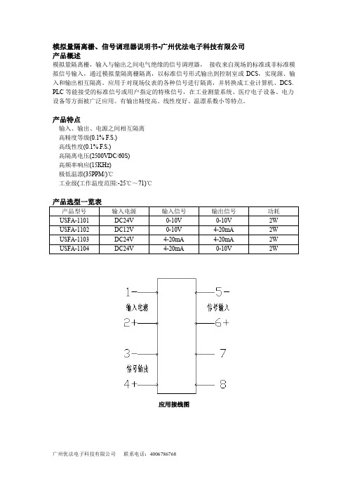
模拟量隔离栅,输入与输出之间电气绝缘的信号调理器,接收来自现场的标准或非标准模拟信号输入,通过模拟量隔离栅隔离,以标准信号形式输出到控制室或DCS,实现源、输入和输出相互隔离。
应用于对现场仪表的各种信号进行隔离,并转换成工业计算机、DCS、PLC等能接受的标准信号或用户指定的特殊信号,在工业测量系统、医疗电子设备、电力设备等方面被广泛应用。
有输出精度高、线性度好、温漂系数小等特点。
产品特点
输入、输出、电源之间相互隔离
高精度等级(0.1%F.S.)
高线性度(0.1%F.S.)
高隔离电压(2500VDC/60S)
高频率响应(15KHz)
极低温漂(35PPM/)℃
工业级(工作温度范围:-25℃~71)℃
产品选型一览表
产品型号输入电源输入信号输出信号功耗USFA-1101DC24V0-10V0-10V2W
USFA-1102DC12V0-10V4-20mA2W
USFA-1103DC24V4-20mA4-20mA2W
USFA-1104DC24V4-20mA0-10V2W
应用接线图
广州优法电子科技有限公司联系电话:4006786768。

MSC301直流信号隔离器MSC301直流信号隔离器,用于标准的4~20mADC或1~5VDC直流信号隔离转换为4~20mADC直流信号输出。
规格型号及代码端子编号与接线MSC302隔离配电器MSC302隔离配电器向现场二线制变送器提供工作电源,同时将现场二线制变送器的电流信号转化为4~20mADC或1~5VDC直流信号输出。
规格型号及代码端子编号与接线MSC304热电阻温度变送器MSC304热电阻温度变送器,将现场热电阻的电势信号隔离转换为一路或二路与温度范围相对应的直流信号输出。
且每一路输入/电源/输出完全隔离。
规格型号及代码端子编号与接线MSC303热电偶温度变送器MSC303热电偶温度变送器,将现场热电偶的电势信号隔离转换为温度范围相对应的直流信号输出。
主要技术指标供电电源:24VDC±10%;精度:±0.1% F.S(Δ>10mV)±0.2% F.S(10mV>Δ>5Mv)输出负载:电流输出≤750Ω、电压输出≥500kΩ温度漂移:±150 PPM/℃绝缘电阻:100MΩ/500VDC绝缘强度:1000V/1min 功耗:≤1.5W型号说明 MSC303-I II III IV 热电偶温度变送器输入1信号1 K型热电偶2 S型热电偶3 E型热电偶4 B型热电偶5 R型热电偶6 T型热电偶7 J型热电偶G 其他热电偶输入2信号0 无输入2输出1信号2 0~5VDC3 1~5VDCB 0~20mA DCC 4~20mA DC G 其他量程输出2信号0 无输出22 0~5VDC3 1~5VDCB 0~20mA DCC 4~20mA DC G 其他量程端子编号与接线MSC305滑线电阻变送器MSC305型滑线电阻变送器,将滑线电阻滑动臂的电阻变化信号隔离转换为与其阻值对应的4~20mADC或1~5VDC直流信号输出。
供电电源:24VDC±10% 激励电流:≤0.3Ma精度:±0.1% F.S线性:输出于被测电阻呈线性关系。
试验装置简介过程控制系统所采用旳试验装置一般可分为两类,一类为物理模型试验装置,一类为半实物仿真试验装置。
课程中多种试验都可以在这两类装置上实现。
一、物理模型试验装置这一类试验装置是由真实旳物理模型实现旳。
其长处是装置中有真实旳流体(清洁旳水)流动,采用真实旳测量装置和真实旳控制阀。
可给学生非常真实旳感官印象。
一般都采用清洁旳循环水作为工艺介质,因此工艺参数只有液位和流量。
有些试验装置尚有电加热设备,增长了温度参数。
这一类试验装置旳局限性是参数比较单一,有一定旳非线性。
具有加热功能旳装置,会随试验旳进行循环水温度会逐渐增高,这会导致温度控制不理想。
下面是使用比较旳几种物理模型试验装置1.普及型控制系统试验装置下面是一种比较经典旳普及型控制系统试验装置。
该装置由北京化工大学信息学院自动化系自行研制。
试验装置两部分构成:其一是包括测量变送器和控制阀在内旳工艺设备;其二是作为控制工具计算机。
装置上共测量四个参数:上水槽液位、下水槽液位、流量1和流量2。
变送器旳4~20mA信号接到信号调理板上,通过调理后旳电压信号通过专用电缆连接到插在计算内旳A/D+D/A板上。
系统用仪表旳电源、D/A 电源、计算机电源、水泵旳按钮开关、信号灯等设备都集成、组装在一种控制箱。
图F.41所示是自动化系统试验室旳物理模型试验装置。
图F.42所示为工艺设备原理图。
图中有三只水槽,槽1、槽2为被控对象,它们旳液位高度L1及L2分别通过两台差压变送器测出。
槽3为储槽,是为了构成水得循环而设置得。
储槽3中旳水通过水泵1或2抽出,通过孔板和控制阀后送入槽1或槽2(视手动阀1、2、3、4旳开闭而定),两路水管中旳水流量大小分别通过各自旳差压变送器(与孔板配合)测出。
槽1中旳水通过线性化流出口流入槽2,槽2中旳水又通过其自身旳线性化流出口流回到储槽3中。
这样对水来说,一直处在循环状态。
图F.41 物理模型试验装置图本装置除比值试验外,一般状况下F l所在旳管道为主物料管道,F2管线则作为加干扰用。
MVP3300智能电气阀门定位器 Intelligent Electropneumatic valve Positioner用户手册User Manua1用户须知 (1)1.1安全指示 (1)1.2开箱清单 (1)1.3重要信息提示 (1)2概述 (1)2.1功能介绍 (2)2.2特点 (2)2.3防雷特性 (2)3技术参数 (3)4安装说明 (4)4.1外形尺寸 (4)4.2机构安装 (4)4.3气路连接 (7)4.4电气连接 (7)5调节操作 (9)5.1操作界面说明 (9)5.2用户菜单 (10)5.3初始化 (12)5.4诊断 (14)5.5报警 (14)5.6参数列表 (16)6参数解释 (17)7使用异常与维护保养 (21)7.1异常状况排除 (21)7.2维护保养 (22)8运输和贮存 (22)9订货须知 (23)9.1产品型号 (23)9.2其它可选项 (23)1用户须知1.1安全指示定位器先上电,后供气源;产品使用过程中,不要随意的触摸反馈连接装置;产品必须正确安装、正确操作和正确维护。
1.2开箱清单MVP3300智能阀门定位器;安装配件;用户手册;另外订制附件,详见装箱清单。
1.3重要信息提示为了您能更好地应用这份说明,以及保障你在调试,运行和维修这台仪器时的安全,请注意下列符号的用途:符号标语解说注意注意注意指潜在的危险,如不能避免,可能会损害产品本身或周围物体。
(危险物)提示提示提示是指有用的或特别的被忽视的能影响操作条件或产品功能的事物。
(不包含危险的或有害的情形)在安装和调试前请认真阅读此手册。
2概述MVP3300智能阀门定位器为深圳万讯自控股份有限公司推出的智能型两线制现场仪表。
本定位器作为气动阀门的配套控制部件,广泛运用于石油、化工、电力、冶金、轻工等领域的自动控制系统中。
MVP3300智能阀门定位器接受来自控制系统的4~20mA阀位设定信号,通过A/D转换得到阀位设定值;同时通过位置传感器得到实际的阀位信号;两者经过控制软件的计算处理,从而控制气动执行机构的进气与排气,驱动阀位到达设定点(如图1所示)MVP3300智能阀门定位器其采用德国原装进口压电阀等核心部件,是基于微处理器技术的高性能电/气阀门定位器,能很好地克服摩擦力和阀芯上的不平衡力,提高调节阀的响应速度,使其定位迅速准确。
地下管廊概念一、名词解释:地下管廊又称共同沟,它是实施统一规划、设计、施工和维护,建于城市地下用于敷设市政公用管线的市政公用设施。
是指在城市地下用于集中敷设电力、通信、广播电视、给水、排水、热力、燃气等市政管线的公共隧道。
地下综合管廊对满足民生基本需求和提高城市综合承载力发挥着重要作用。
它避免由于敷设和维修地下管线频繁挖掘道路而对交通和居民出行造成影响和干扰,保持路容完整和美观。
降低了路面多次翻修的费用和工程管线的维修费用。
保持了路面的完整性和各类管线的耐久性。
便于各种管线的敷设、增减、维修和日常管理。
由于共同沟内管线布置紧凑合理,有效利用了道路下的空间,节约了城市用地。
由于减少了道路的杆柱及各种管线的检查井、室等,优美了城市的景观。
由于架空管线一起入地,减少架空线与绿化的矛盾。
二、题材看点:【背景】我国正处在城镇化快速发展时期,地下基础设施建设滞后。
推进城市地下综合管廊建设,有利于提高城市综合承载能力和城镇化发展质量,有利于增加公共产品有效投资、拉动社会资本投入、打造经济发展新动力。
【政策】1、在7月末举行的国务院常务会议上,城市地下综合管廊建设已被重点提及。
会议指出,针对长期存在的城市地下基础设施落后的突出问题,要从我国国情出发,借鉴国际先进经验,在城市建造用于集中敷设电力、通信、广电、给排水、热力、燃气等市政管线的地下综合管廊,作为国家重点支持的民生工程。
并且有望纳入整个城市基础设施建“十三五”规划2、到2020年,建成一批具有国际先进水平的地下综合管廊并投入运营,管线安全水平和防灾抗灾能力明显提升;鼓励由企业投资建设和运营管理地下综合管廊,推广运用政府和社会资本合作(PPP)模式,通过特许经营、投资补贴、贷款贴息等形式,鼓励社会资本组建项目公司参与城市地下综合管廊建设和运营管理。
【前景】根据前瞻产业研究院最新发布的《2015-2020年中国城市地下管线探测行业发展前景与投资战略规划分析报告》显示,我国城市仅供水、排水、燃气、供热4类市政地下管线长度已超过148万公里。