B3DxxxL规格书
- 格式:pdf
- 大小:203.59 KB
- 文档页数:3

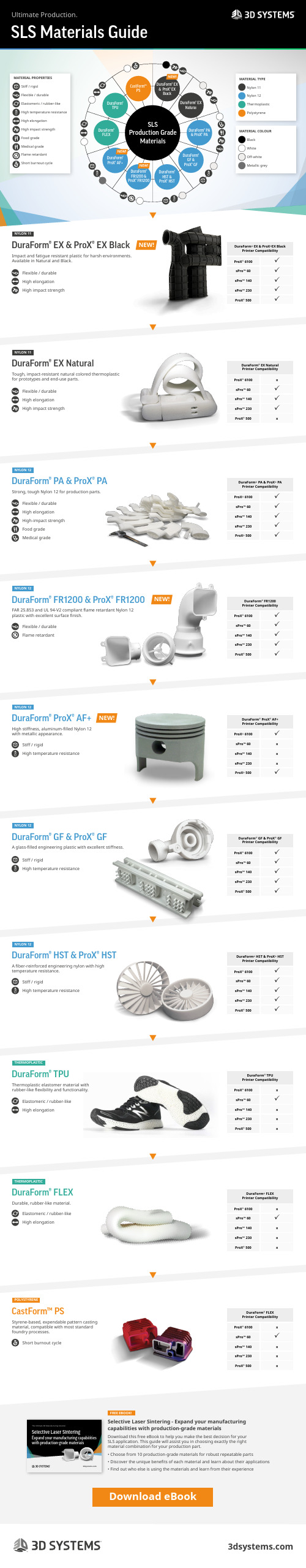
DuraForm® EX & ProX® EX BlackDuraForm® EX NaturalDuraForm® ProX® AF+DuraForm® TPUDuraForm® FLEXDuraForm® HST & ProX® HSTCastForm™PSDuraForm® PA & ProX® PADuraForm® FR1200 & ProX® FR1200DuraForm® GF & ProX® GFSLSProduction GradeMaterialsNEW!NEW!NEW!Flexible / durableFlame retardantStiff / rigidHigh temperature resistanceStiff / rigidHigh temperature resistanceStiff / rigidHigh temperature resistanceSLS Materials GuideUltimate Production.NEW!DuraForm® EX & ProX® EX BlackDuraForm® EX NaturalDuraForm® PA & ProX® PADuraForm® FR1200 & ProX® FR1200DuraForm® ProX® AF+DuraForm® GF & ProX® GFDuraForm® HST & ProX® HSTDuraForm® TPUDuraForm® FLEXCastForm™ PSNYLON 11NYLON 11NYLON 12NYLON 12NYLON 12NYLON 12NYLON 12THERMOPLASTICTHERMOPLASTICPOLYSTYRENEFREE EBOOK!DuraForm ® EX & ProX ®EX BlackPrinter Compatibility ProX ® 6100 sPro™ 60 sPro™ 140 sPro™ 230 ProX ® 500DuraForm ® EX Natural Printer Compatibility ProX ® 6100xsPro™ 60 sPro™ 140 sPro™ 230ProX ® 500xDuraForm ® PA & ProX ® PA Printer Compatibility ProX ® 6100 sPro™ 60 sPro™ 140 sPro™ 230 ProX ® 500DuraForm ® FR1200 Printer Compatibility ProX ® 6100 sPro™ 60 sPro™ 140 sPro™ 230 ProX ® 500DuraForm ® ProX ® AF+ Printer Compatibility ProX ® 6100sPro™ 60x sPro™ 140x sPro™ 230xProX ® 500DuraForm ® GF & ProX ® GF Printer Compatibility ProX ® 6100 sPro™ 60 sPro™ 140 sPro™ 230 ProX ® 500DuraForm ® HST & ProX ® HSTPrinter Compatibility ProX ® 6100 sPro™ 60 sPro™ 140 sPro™ 230 ProX ® 500DuraForm ® TPU Printer Compatibility ProX ® 6100xsPro™ 60sPro™ 140x sPro™ 230x ProX ® 500xDuraForm ® FLEX Printer Compatibility ProX ® 6100xsPro™ 60sPro™ 140x sPro™ 230x ProX ® 500xDuraForm ® FLEX Printer Compatibility ProX ® 6100xsPro™ 60sPro™ 140x sPro™ 230x ProX ® 500xFlexible / durable High elongationHigh impact strengthFlexible / durable High elongationHigh impact strengthFlexible / durable High elongation High-impact strength Food gradeMedical gradeImpact and fatigue resistant plastic for harsh environments. Available in Natural and Black.Tough, impact-resistant natural colored thermoplastic for prototypes and end-use parts.Strong, tough Nylon 12 for production parts.FAR 25.853 and UL 94-V2 compliant flame retardant Nylon 12 plastic with excellent surface finish.High stiffness, aluminum-filled Nylon 12 with metallic appearance.A glass-filled engineering plastic with excellent stiffness.A fiber-reinforced engineering nylon with high temperature resistance.Thermoplastic elastomer material with rubber-like flexibility and functionality.Durable, rubber-like material.Styrene-based, expendable pattern casting material, compatible with most standard foundry processes.Selective Laser Sintering - Expand your manufacturing capabilities with production-grade materialsDownload this free eBook to help you make the best decision for your SLS application. This guide will assist you in choosing exactly the right material combination for your production part.• Choose from 10 production-grade materials for robust repeatable parts • Discover the unique benefits of each material and learn about their applications• Find out who else is using the materials and learn from their experienceElastomeric / rubber-likeHigh elongationElastomeric / rubber-likeHigh elongationShort burnout cycleMATERIAL TYPE Nylon 11Nylon 12Thermoplastic PolystyreneMATERIAL COLOUR Black WhiteOff-whiteMetallic greyNEW!NEW!Download eBookMATERIAL PROPERTIES Stiff / rigid Flexible / durable Elastomeric / rubber-like High temperature resistance High elongation High impact strength Food grade Medical grade Flame retardantShort burnout cycleSelective Laser SinteringExpand your manufacturing capabilities with production-grade materialsThe Ultimate 3D Manufacturing Solution。

Philips3D LCD monitor, LED Array backlight with Easy 3DG Line23" (58.4 cm)3D, FPR glasses236G3DHSBExperience 3D gamingon your big screenEngage yourself with 3D games on the Philips 236 G LED monitor. With a large display,flicker-free 3D glasses and multiple HDMI inputs, gaming just got more exciting!Engaging 3D viewing experience•Easy 3D for a flicker-free gaming experience•Flicker-free 3D glasses for easy viewing•Play 3D games on your PC with bundled software•Transform 2D to 3D with direct key access•Auto 3D with the latest Blu-ray and game consoles with HDMIGreat picture quality•Full HD LED technology for brilliant 2D images•2 ms SmartResponse for fast 2D gaming•SmartContrast 20,000,000:1 for incredible rich black details•SmartImage: Optimised user-friendly display experience•SmartControl: For easy display tuningGreener every day•Mercury Free eco-friendly display•Energy Star for energy efficiency and low power consumptionHighlights Easy 3DEasy 3D ensures you get long hours of comfort while watching 3D thanks to the flicker-free, low ghosting performance. The compatible 3D glasses are lightweight and do not require batteries. Enjoy 3D easily at home today! Flicker-free 3D glassesEntertain yourself with the light weight, easy-to-use polarised 3D glasses. These flicker free 3D glasses are not only easy to replace and maintain, but they are also affordable enough that finally your whole family has the option to obtain individual glasses. As there are no batteries or cables involved, you are now finally free to enjoy it as long as you want to. Transform 2D to 3DTransform your 2D collection to 3D at the push of a button! Easily accessible via a hot key on the bezel, this feature will re-invent your favourite 2D collection of games, movies and video to 3D.Auto 3D with HDMIWith Blu-ray gaming and movie players with HDMI 1.4a compatible connection, the Philips 3D display will auto-switch to 3D mode and give you awesome images straight away. No more fussing with adjustments!SmartImageSmartImage is an exclusive leading edge Philipstechnology that analyses the content displayedon your screen and gives you optimised displayperformance. This user-friendly interfaceallows you to select various modes like Office,Image, Entertainment, Economy etc., to fit theapplication in use. Based on the selection,SmartImage dynamically optimises thecontrast, colour saturation and sharpness ofimages and videos for ultimate displayperformance. The Economy mode optionoffers you major power savings. All in real timewith the press of a single button!SmartContrast ratio 20,000,000:1You want the LCD flat display with the highestcontrast and most vibrant images. Philipsadvanced video processing combined withunique extreme dimming and backlight-boosting technology results in vibrant images.SmartContrast will increase the contrast withexcellent black level and accurate rendition ofdark shades and colours. It gives a bright,lifelike picture with high contrast and vibrantcolours.SmartControlPC software for fine tuning displayperformance and settings. Philips offers userstwo choices for display setting adjustment.Either navigate the multi-level On-ScreenDisplay menu through buttons on the displayitself or use the Philips SmartControl softwareto easily adjust the various display settings in afamiliar way2 ms SmartResponseSmartResponse is an exclusive Philipsoverdrive technology that when turned on,automatically adjusts response times to specificapplication requirements like gaming and films,which require faster response times in orderto produce judder, time-lag and ghost imagefree imagesMercury FreePhilips monitors with LED backlighting are freefrom Mercury, one of the most toxic naturalsubstances, which affects humans and animals.This reduces the environmental impact of thedisplay throughout its lifecycle, frommanufacturing to disposal.Issue date 2017-11-16 Version: 2.0.112 NC: 8670 000 88443 EAN: 87 12581 63916 7© 2017 Koninklijke Philips N.V.All Rights reserved.Specifications are subject to change without notice. Trademarks are the property of Koninklijke Philips N.V. or their respective owners.SpecificationsPicture/Display•LCD panel type: TFT-LCD•Backlight type: W-LED system•Panel Size: 23 inch/58.4 cm•Aspect ratio: 16:9•Optimum resolution: 1920 x 1080 @ 60 Hz •Response time (typical): 5 ms •SmartResponse: 2 ms in 2D mode (Grey to Grey)•Brightness: 250 cd/m²•Contrast ratio (typical): 1000:1•SmartContrast: 20,000,000:1•Pixel pitch: 0.265 x 0.265 mm•Viewing angle: 170º (H)/160º (V), @ C/R > 10•3D Viewing angle: 80º (H)/12º (V), 3D CT<10•Picture enhancement: SmartImage•Display colours: 16.7 M•Effective viewing area: 509.2 (H) x 286.4 (V) mm •Scanning Frequency: 30 - 83 kHz (H) / 50 - 75 Hz (V)•sRGBConnectivity•Signal Input: HDMI x 2, VGA (Analogue)•Sync Input: Separate Sync, Sync on Green •Audio (In/Out): HDMI audio out Convenience•User convenience: SmartImage, 3D, Power On/ Off, Input, Menu•OSD Languages: English, French, German, Italian, Portuguese, Russian, Simplified Chinese, Spanish •Other convenience: Kensington lock•Plug and Play Compatibility: DDC/CI, Mac OS X, sRGB, Windows 7Stand•Tilt: -5/+20 degreePower•On mode: 23.85 W (typical) (energyStar 5.0 test method)•Standby mode: 0.5 W (typ.)•Off mode: <0.3 W•Power LED indicator: Operation - White, Standbymode - White (flashing)•Power supply: 100-240 VAC, 50-60 Hz, Built-inDimensions•Product with stand (mm): 566 x 426 x 219 mm•Product without stand (mm): 566 x 355 x 54 mm•Packaging in mm (W x H x D): 615 x 441 x 115 mmWeight•Product with stand (kg): 3.26 kg•Product without stand (kg): 3.03 kg•Product with packaging (kg): 4.61 kgOperating conditions•Temperature range (operation): 0°C to 40°C °C•Temperature range (storage): -20°C to 60°C °C•Relative humidity: 20%–80% %•MTBF: 30,000 hour(s)Sustainability•Environmental and energy: EPEAT Silver, RoHS,EnergyStar 5.0, Lead-free, Mercury Free•Recyclable packaging material: 100 %Compliance and standards•Regulatory Approvals: BSMI, CE Mark, FCC ClassB, GOST, PSB, SASO, SEMKO, TUV Ergo, TUV/GS, UL/cUL, WEEECabinet•Colour: Black•Finish:Glossy/Texture3D Requirements•Software: Free Tridef 3D software bundle•PC hardware: Requires AMD/nVidia VGA card*•Auto 3D: Requires HDMI 1.4a*If you experience any discomfort such as dizziness, headache ordisorientation, we recommend not watching 3D for extendedperiods of time.*Parents should monitor their children during 3D viewing and ensurethey do not experience any discomfort as mentioned above.Watching 3D is not recommended for children under 6 years of age.*Please read the instruction manual carefully to learn more about 3Dand health*For VGA card and other requirements for 3D operation, please visit/support for further details.。
ASSEMBLY MANUALDIY 3D PRINTER KITB2X300VERSIONDATEDESCRIPTIONPART NUMBERSV0.2018050303th May 2018Beta-tester version 1212200001 to 1212200008V1.201811087th November 2018First release version 1212300001 to ------------VERSIONSV2.2018112727th November 2018Changes in pages: 16, 41, 58, 591212300001 to ------------V3.2018121414th December 20181212300001 to ------------Changes in page 42V4.2018122020th December 2018Changes in pages: 3, 42, 43, 571212300001 to ------------V5.201901099th January 20191212300001 to ------------Changes in pages: 47, 49, 55V6.2019011818h January 2019Changes in pages: 47, 49, 551212300001 to ------------V7.2019051313th May 20191212300001 to ------------Changes in page 58NEEDED TOOLSBefore you start to build your B2X300 3D printer, check if you have the necessary toolsto do it. You will need the following:You will need a set of hex key forthe assembly.There is a 1.5mm hex key supplied with the kit.Sometimes you might need to use some extra strengh assemblingthe printer .You will need it towards the end.Always a helpful tool.You will also need to remove some strands from the printed vparts with a cutter .Take great care not to cut yourself when doing this.There is a Double Ring Spanner included in the Structure Frame, which can make the screw taskeasier and quicker .SET OF HEX KEYSSOFT FACE HAMMERFLATHEAD SCREWDRIVERREGULAR PLIERSBOX CUTTERDOUBLE RING SPANNERThere is also a nozzle changing tool in the Structure Frame, wichwill be usefull on a future changing nozzle process.NOZZLE CHANGERYou need a marker to write on thelabels, for better guidance while building B2X300.MARKER2BOX 0Main Metal Frame of your B2X300, guides and Threaded Rods.BOX 1All the motors neededare inside this box.BOX 2Inside this box you have the glass, heated bed and its cabling, and the Printed Parts too.BOX 4Behold the Motherboard, the Display and some of the Electronic components.BOX 5The Extruder and Auto-Calibration Module is in this box.BOX 3Mechanic Partsyou need are right here.BOX 6In this box you have the Power Supply.To make recognizing each type of component easier, we’ve assigned a shape and colour to each type.This way, we tried to divide all the components in boxes, just to make it easy for you.STRUCTURE MECHANICS ELECTRONICS PRINTED PARTS3A – Assembling the structure.......................................................................................p.7B – Assembling the build plate structure.....................................................................p.19C – Assembling the X-Axis............................................................................................p.25D – Assembling the X-Axis to the structure.................................................................p.33E – Assembling the Extruder ........................................................................................p.40F – Assembling the Electronics....................................................................................p.51You can also consult B2X300 3D printer DIY KIT video tutorials playlist on BEEVERYCREATIVE’s Youtube channelWe aim to make it simple for you, so we have created areas in this manual to help you build your B2X300 3D printer as well and as easily as you can.RULERThis area will tell you how to build each stepThis letter and number will help to guide yourbuilding process.There is a letter for each set of steps of the assembly,and a number for each step.This area will tell you from wich perspectiveyou are buildingWhich kit materials you will use for each stepHere you will know what tools you mightneed to useSpace for some tips and detailed instructionsWhat your assembly should look like after each step.This ruler helps you to measure the screwsand other mechanincs partsTECHNICAL SPECIFICATIONSLAYER RESOLUTION (user defined)3D PRINTING TECHNOLOGYPRINTING MATERIALMAX. BUILD VOLUME (up to)HEATED BUILD PLATEHEATED BUILD PLATE TEMPERATUREDUAL EXTRUDERNOZZLE DIAMETEREXTRUDER MAX TEMPERATURETRINAMIC TMC 2130 DRIVERSFILAMENT END DETECTIONMODULAR MOTHERBOARDSENSORLESS HOMINGPOWER LOSS DETECTION AND RECOVERYEASY OFFSET CALIBRATIONSTRUCTURE MATERIALSPRINTER SIZEWEIGHTAMBIENT OPERATING TEMPERATURESTORAGE TEMPERATUREAC INPUTPOWER CONSUMPTIONCONNECTIVITYINCLUDED ACCESSORIESSUPPORTED FILE TYPESAUTO BED LEVELLINGFIRMWAREELECTRONICSRECOMMENDED 3D PRINTING/ SLICING SOFTWARE SPEEDASSEMBLY EXPERIENCE 50 - 300 micronsFFFPLA, ABS, PETG, NYLON, Wood Composits, Metal Composits, HIPLA, ABS-PC, HIPS, Carbon Composits300 x 200 x 300 mm (11.81 x 7.87 x 11.81 in)Yes (with 4mm removable glass surface)50ºC (122ºF) – 130ºC (266ºF)Yes, with two nozzle dual extruder0.4mm | 0.4mm (other nozzle diameters available)300ºC (572ºF)Print more silently, especially on stealth mode. Faster printing speeds with reduced vibrations and improved motion precision, without compro-mising print quality. Up to 256 microsteps.Ability to detect absence of filamentAllows for future upgrades and customizationNo limit switches required, thanks to the trinamic driversPossibility to resume printing after a power lossSimple one step method, does not require mutiple test printsHigh-quality powder-coated steel frame, Steel guides Removable glass build plate,Full metal dual extruder56 x 37.5 x 60 cm (22,04 x 14,76 x 23,62 in)12kg (26,45 lb)10-30ºC (50-86ºF)5-35ºC (41º -95º F)110-240VAC | 50-60Hz360 WSD Card | USBEU power cable | USB cable | SD card | Grease.gcodeAuto Bed Levelling using a 15 point mesh, interpolated to 45 virtual pointsMarlin basedMKS GenCura | Slic3r | Simplify 3Dup to 200 mm/s+/- 6 hoursSAFETY INFORMATIONADULT SUPERVISIONHIGH TEMPERATURESCOOL AND WELL-VENTILATEDENVIRONMENTMOVING PARTSOther information you need to knowAfter assembling your B2X300, don’t drop/knock/damage it and don’t connect it to zvvanything that hasn’t been previously validated by BEEVERYCREATIVE.Make sure gases, explosive and other flammable materials aren’t kept, stored or transported with your B2X300 3D printer or its parts.Because we can’t stress this enough,this 3D printer was developed to be used by adults.Should you wish that children also use it,you must supervise them atall times while they do so.You must also take great care withsmall printed objects,because children might try to swallow them,which poses a danger of them choking.Whenever this 3D printer is functioning,some mechanical parts canreach high temperatures,which can cause serious burns if touched.For that reason you must alwaysbe careful not to touch it.For better results with your 3D printer,it is recommended you maintain anacceptable level of air quality around the printer.Environments with some ventilation are alsorecommended so as to renew the air if you chooseto print with materials that release odors.Whenever it’s functioning, this 3D printerhas moving parts.For that reason, you should alwayskeep a safe distancefrom the printer while it’s operating.Even though the B2X300 3D printer was designed to be as safe as possible, we would like to remind you it was conceived to be used by adults.Still, there are safety concerns you must keep in mind:WARRANTY INFORMATIONB2X300 is a DIY 3D printer assembled by the user.Its warranty is assured for the components that are included with the KIT.Six month warranty guaranties the replacement of defective manufactured parts. BEEVERYCREATIVE may request the return of this part in order to improve future de-velopments.Warranty will be voided if:- inappropriate handling during assembly takes place.- the user makes incorrect connections, breaks or damages parts during assembly. Before assembling your B2X300 you must read thoroughly the Terms and Conditions of the BEEVERYCREATIVE Standard Warranty on our website:A ASSEMBLING THE STRUCTURE8F R O N TRULERBUTTON HEAD SCREW DIN7380 M4X10222SERRATED LOCK WASHER DIN6798J M4HEX. THIN NUT 1 DIN439 M4STRUCTURE MECHANICS ELECTRONICS PRINTED PARTSRemove the pieces from the structure with a regular pliers⚠9B AC K222BUTTON HEAD SCREW DIN7380 M4X10SERRATED LOCK WASHER DIN6798J M4HEX. THIN NUT 1 DIN439 M4STRUCTURE MECHANICS ELECTRONICSPRINTED PARTS10888BUTTON HEAD SCREW DIN7380 M4X10SERRATED LOCK WASHER DIN6798J M4HEX. THIN NUT 1 DIN439 M4STRUCTURE MECHANICS ELECTRONICSPRINTED PARTS11STRUCTURE MECHANICS ELECTRONICS PRINTED PARTS12STRUCTURE B A C KMECHANICS 333BUTTON HEAD SCREW DIN7380 M4X10SERRATED LOCK WASHER DIN6798J M4HEX. THIN NUT 1 DIN439 M4ELECTRONICSPRINTED PARTS13STRUCTURE F R O N TMECHANICS 222BUTTON HEAD SCREW DIN7380 M4X10SERRATED LOCK WASHER DIN6798J M4HEX. THIN NUT 1 DIN439 M4ELECTRONICSPRINTED PARTS14F R O N T444STRUCTURE MECHANICS ELECTRONICSPRINTED PARTSBUTTON HEAD SCREW DIN7380 M4X10SERRATED LOCK WASHER DIN6798J M4HEX. THIN NUT 1 DIN439 M415333STRUCTURE MECHANICS ELECTRONICSPRINTED PARTSBUTTON HEAD SCREW DIN7380 M4X10SERRATED LOCK WASHER DIN6798J M4HEX. THIN NUT 1 DIN439 M416CYL. HEAD SCREW DIN912 M3X61212PLAIN WASHER DIN125 M3NEMA17 STEPPER MOTOR Y AXISSTRUCTURE MECHANICS ELECTRONICSPRINTED PARTSFRONTLEFT RIGHTZ-AXISmotors screws slightly loose.17F R O N TFLEX COUPLING2STRUCTURE MECHANICS ELECTRONICSPRINTED PARTS18F R O N T112SERRATED LOCK WASHER DIN6798J M5HEX. THIN NUT 1 DIN439 M5FLAT BELT PULLEY11PULLEY GT2 20 TOOTHSTRUCTURE MECHANICS ELECTRONICSPRINTED PARTSBASSEMBLINGTHE BUILD PLATE STRUCTURE20F R O N T“U” CLAMP M44410BED RAISERHEX. THIN NUT 1 DIN439 M4SERRATED LOCK WASHER DIN6798J M482BUTTON HEAD SCREW DIN7380 M4X10STRUCTURE MECHANICS ELECTRONICSPRINTED PARTS4LINEAR BEARING 8øx25MM121F R O N TSTRUCTURE ELECTRONICS PRINTED PARTS GUIDE SUPPORT✓✗✗22F R O NT8HEX. THIN NUT 1 DIN439 M5SERRATED LOCK WASHER DIN6798J M588BUTTON HEAD SCREW DIN7380 M5X20STRUCTUREMECHANICSELECTRONICSPRINTED PARTS23F R O N TSTRUCTURE MECHANICS ELECTRONICSPRINTED PARTSBELT HOLDER LOCK1GT2 RUBBER BELT -0,80m1HEX. THIN NUT 1 DIN439 M41BUTTON HEAD SCREW DIN7380 M4X20rubber belt and finish tightening the screws.11,20m 0,80mCut rubber belt24F R O NTBUILD PLATAFORM SPRING44CYL. HEAD SCREW DIN912 M3X20BUILD PLATAFORM CLIP4STRUCTUREMECHANICSELECTRONICSPRINTED PARTSPCB HEATED BED 314X214MM66HEX. THIN NUT 1 DIN10511 M32CYL. HEAD SCREW DIN912 M3X6C ASSEMBLING THE X-AXIS26F R O N TSTRUCTUREMECHANICSELECTRONICSPRINTED PARTSX SUPPORT1127F R O N T7HEX. THIN NUT 1 DIN439 M4SERRATED LOCK WASHER DIN6798J M4727BUTTON HEAD SCREW DIN7380 M4X20STRUCTURE MECHANICS ELECTRONICSPRINTED PARTSLeave all screws slightly loose.⚠LINEAR BEARING 8øx25MM28F R O N TSTRUCTUREMECHANICSELECTRONICSPRINTED PARTS2HEX. THIN NUT 1 DIN439 M5SERRATED LOCK WASHER DIN6798J M521CYL. HEAD SCREW DIN912 M5X35129F R O N TSTRUCTURE MECHANICS ELECTRONICS PRINTED PARTS130F R O N TSTRUCTUREMECHANICSELECTRONICSPRINTED PARTS8HEX. THIN NUT 1 DIN439 M4SERRATED LOCK WASHER DIN6798J M48MM LINEAR BEARING828BUTTON HEAD SCREW DIN7380 M4X201Leave all screws slightly loose.⚠31B AC K1PULLEY GT2 20 TOOTHPLAIN WASHER DIN125 M333CYL. HEAD SCREW DIN912 M3X6STRUCTURE MECHANICS ELECTRONICSPRINTED PARTSX AXIS NEMA17 STEPPER MOTORUse the marker to label thecable label with X-AXIS selected32F R O N TSTRUCTUREELECTRONICSPRINTED PARTS2LINEAR BEARING 8ø x 45MMLinear guides should be pushed tothe end to fit well enough.⚠DASSEMBLING THE X-AXIS TO THE STRUCTURE34F R O N TSTRUCTUREELECTRONICS PRINTED PARTS35F R O N TSTRUCTURE MECHANICS ELECTRONICSPRINTED PAR TS4F R O N TSTRUCTURE MECHANICS ELECTRONICSPRINTED PARTS8HEX. THIN NUT 1 DIN439 M5SERRATED LOCK WASHER DIN6798J M588BUTTON HEAD SCREW DIN7380 M5X2037F R O N TSTRUCTURE MECHANICS ELECTRONICSPRINTED PARTSCheck if X-AXIS flows freely in the linear guides338STRUCTURE MECHANICS ELECTRONICSPRINTED PARTS39F R O N TSTRUCTURE ELECTRONICS PRINTED PARTSflex couplings (clock wise rotation) guide, adjust it within motors slot holes.E ASSEMBLING THE EXTRUDER41STRUCTUREMECHANICSELECTRONICSPRINTED PARTSLINEAR BEARING SUPPORT1CYL. HEAD SCREW DIN912 M3X2511HEX. THIN NUT 1 DIN10511 M3PLAIN WASHER DIN125 M3B AC K42STRUCTUREMECHANICSELECTRONICSPRINTED PARTSB AC KAUTO-CALIBRATION MODULE1CYL. HEAD SCREW DIN912 M3X2511HEX. THIN NUT 1 DIN10511 M3PLAIN WASHER DIN125 M3Never rotate the sensor manually as it will damage the auto-calibration module, and l eave the sensor cables slightly loose to allow the rotation.STRUCTURE MECHANICS ELECTRONICS PRINTED PARTS B A C KBOWDEN EXTRUDER4CYL. HEAD SCREW DIN912 M3X2044STRUCTUREMECHANICSELECTRONICSPRINTED PARTSBELT HOLDER LOCK1GT2 RUBBER BELT1HEX. THIN NUT 1 DIN439 M4SERRATED LOCK WASHER DIN6798J M411BUTTON HEAD SCREW DIN7380 M4X20Fasten the belt holder slightly, then push the rubber belt with a pliers andfinish tightening the screw.45STRUCTUREMECHANICSELECTRONICSPRINTED PARTSF R O N T46F R O N TSTRUCTURE MECHANICS ELECTRONICS PRINTED PARTS2CYL. HEAD SCREW DIN912 M3X25 1PTFE COUPLER1DRIVER BLOCK EXTRUDER DRIVER 1E0E147B AC KSTRUCTURE MECHANICS ELECTRONICSPRINTED PARTS2CYL. HEAD SCREW DIN912 M3X3022HEX. THIN NUT 1 DIN10511 M3PLAIN WASHER DIN125 M311E0E1Leave all screws slightly loose.⚠1* May be required for some types of 3D printing filament.You can download on this folder:B2X300-hardware/3D Printed Parts/ on https:///beeverycreative .The assembly process is on the First Print video in the B2X300 3D printer DIY KIT playlist at: /user/beeverycreative48STRUCTUREMECHANICSELECTRONICSPRINTED PARTSF R O N T2CYL. HEAD SCREW DIN912 M3X251PTFE COUPLER1DRIVER BLOCKUse the marker to label the cable label with E0 selectedE0E1。
INSTRUTIONS MANUALYORK 3DDimensionsYORK 500 - H 283 mm x W 654 mm x D 452 mmYORK 1000 - H 283 mm x W 1164 mm x D 452 mmCapacityYORK 500 - 1,3 liters ( filtered water)YORK 1000 - 2,6 liters ( filtered water)Autonomy8 hoursVoltage220/240 VFrequency50 HzThe product complies with the European Safety Standards EN60335-2-30 and the European Standard Electromagnetic Compatibility (EMC) EN55014, EN60555-2 and EN60555-3 These cover the essential requirements of EEC Directives 2006/95/EC and 2004/108/ECCongratulations on purchasing your GlammFire appliance. This quality product has been designed with precision and rigour that characterizes us to offer you pleasant and soothing moments.Please read the instructions for use carefully and effective before using the appliance.Keep this Manual in a safe place.Please read this manual before using your appliance and keep it for future reference. All presented warnings must be respected.The information provided in this manual is subject to change without notice.GlammFire. PAG./3 INDEX1—Supplied material 4 2—Components 4 3—Installation 43.1—Installation procedures4—General dimensions 6 5—After-sale service 6 6—Warranty 71—Supplied material1. York 3D base2. KIT Glamm 3D Plus2—Components1. York 3D base2. KIT Glamm 3D Plus3—InstallationThe fireplace installation surface must be as level as possible.It is recommended to maintain a good ventilation of the place of installation of the fireplace. Before using the product, please read this Instructions Manual and the Kit Glamm 3D Plus Instructions Manual care-fully. All warnings must be duly respected.1.2.1.3.1—Installation proceduresIt is recommended to unpack the fireplace with the utmost precaution. Position the base at the desired location.Figure 1: York 3D base.2.Figure 2: Placing the Kit Glamm 3D Plus on the base.Placing the Kit Glamm 3D Plus inside the base.NOTE: This product has leveling feet to adjust height.Figure 3: KIT Glamm 3D Plus frontal view.Leveling Feet4—General dimensionsYORK 3D 500382452 654YORK 3D 1000382452 11645—After-Sales ServiceIn case of doubt or any anomaly, do not use the fireplace and please contact a specialized technician.6– WarrantyIn order to activate your GlammFire 2 year warranty, please register your new GlammFire product at /en/about/warranty or complete your warranty card and return it to us, along with a copy of the proof of purchase, at our address within 30 days of purchase.All our Bioethanol Fireplaces and Burners, Electric Fire-places, Fire Pits & Barbecues carry a warranty against defects of manufacture and faulty workmanship for a period of 2 years from the date of purchase.This warranty does not cover glass replacement, batteries, damage caused by accident or misuse of the appliance, or the assembly/disassembly not indicated in the instruction manuals. If the product fails (not considering the above mentioned events) within the warranty period, defective pieces will be replaced free of charge if it is proved any de-fect of manufacture. Regarding defective pieces, they will be sent free of charge and their switch is responsibility of the retailer responsible for the purchase of the appliance.Our warranty is offered as an addition to your statutory rights. It is applicable to the original purchaser only, non-transferable. All repairs must only be fitted by an authorised service technician. Use of spare parts other than those supplied by the manufacturer will invalidate the appliance warranty and must only be fitted by an authorised service technician.IMPORTANT:Registering your product does not require proof of purchase, if it will be made on our website, and must be based on the date of purchase. It will be assumed that registration information accurately reflects the infor-mation on the proof of purchase which will be required upon servicing of any/all products under warranty.If the information conflicts, information stated on the proof of purchase will be deemed accurate and true and war-ranty will be assessed accordingly.GlammFire is always concerned with the environment. This is reflected by the projection of its products and packaging. Focusing on the reduction of energy consumption, raw materials, natural resources and quantity of waste generated, GlammFire follows the policy of the 4R's (Reduce, Reuse, Recycle and Recover). Thus GlammFire has in mind the use of long lasting products as well as reusable and recyclable products.GlammFire recommends reusing the packaging GlammFire separately and deposit plastic, paper, cardboard and glass in the appropriate collection point."In nature nothing is created, nothing is lost, everything is transformed."Antoine Laurent de Lavoisier GlammFire fireplaces are manufactured under the strict Standard of the world recognized ISO 9001:2008 (TUV) Quality Assurance Certificate.GlammFire products are designed with superior components and materials, assembled by trained craftsmen who take great pride in their work.Once assembled the complete fireplace is thoroughly inspected by a qualified technician before packaging to ensure that you, the customer, receive the quality product that you expect from GlammFire.Recuperadores Pachinha Lda.Zona Industrial da Lagoa, Lote G14950-850 CORTES - MONÇÃO PORTUGAL Tel(+351) 251 654 800Fax(+351) 251 654 801******************。
1.Product profile1.1General descriptionPNP low V CEsat Breakthrough in Small Signal (BISS) transistor and NPN Resistor-Equipped T ransistor (RET) in a SOT457 (SC-74) small Surface Mounted Device (SMD)plastic package.1.2FeaturesI Low V CEsat (BISS) and resistor-equipped transistor in one package I Low threshold voltage (<1V) compared to MOSFET I Low drive power required I Space-saving solutionIReduction of component count1.3ApplicationsI Supply line switches I Battery charger switchesI High-side switches for LEDs, drivers and backlights IPortable equipment1.4Quick reference data[1]Pulse test: t p ≤300µs;δ≤0.02PBLS2003D20 V PNP BISS loadswitchRev. 02 — 27 August 2009Product data sheetTable 1.Quick reference data Symbol ParameterConditions Min Typ Max Unit TR1; PNP low V CEsat transistorV CEO collector-emitter voltage open base--−20V I C collector current (DC)--−1A R CEsatcollector-emitter saturation resistanceI C =−1A;I B =−100mA [1]-185280m ΩTR2; NPN resistor-equipped transistor V CEO collector-emitter voltage open base--50V I O output current --100mA R1bias resistor 1 (input)71013k ΩR2/R1bias resistor ratio0.811.22.Pinning information3.Ordering information4.Marking5.Limiting valuesTable 2.Pinning Pin Description Simplified outlineSymbol1emitter TR12base TR13output (collector) TR24GND (emitter) TR25input (base) TR26collector TR1132456654123R2TR1TR2R1sym036Table 3.Ordering informationType numberPackage NameDescriptionVersion PBLS2003DSC-74plastic surface mounted package; 6leadsSOT457Table 4.Marking codesType number Marking code PBLS2003DF8Table 5.Limiting valuesIn accordance with the Absolute Maximum Rating System (IEC 60134).Symbol ParameterConditions Min Max Unit TR1; PNP low V CEsat transistorV CBO collector-base voltage open emitter -−20V V CEO collector-emitter voltage open base -−20V V EBO emitter-base voltage open collector -−5V I C collector current (DC)-−1A I CM peak collector current t p ≤300µs-−2A I B base current (DC)-−0.3A I BM peak base current t p ≤300µs -−0.6A P tottotal power dissipationT amb ≤25°C[1]-250mW [2]-350mW [3]-400mW[1]Device mounted on an FR4 Printed-Circuit Board (PCB), single-sided copper, tin-plated and standard footprint.[2]Device mounted on an FR4 PCB, single-sided copper, tin-plated, mounting pad for collector 1cm 2.[3]Device mounted on a ceramic PCB, Al 2O 3, standard footprint.TR2; NPN resistor-equipped transistorV CBO collector-base voltage open emitter -50V V CEO collector-emitter voltage open base -50V V EBO emitter-base voltage open collector-10V V Iinput voltage positive -+40V negative-−10V I O output current -100mA I CM peak collector current t p ≤300µs -100mA P tot total power dissipation T amb ≤25°C[1]-200mW Per deviceP tottotal power dissipation[1]-400mW [2]-530mW [3]-600mW T stg storage temperature −65+150°C T j junction temperature -150°C T ambambient temperature−65+150°C(1)Ceramic PCB, Al 2O 3, standard footprint (2)FR4 PCB, mounting pad for collector 1cm 2(3)FR4 PCB, standard footprintFig 1.Power derating curvesTable 5.Limiting values …continuedIn accordance with the Absolute Maximum Rating System (IEC 60134).Symbol ParameterConditions Min Max Unit T amb (°C)01601204080006aaa4140.40.20.60.8P tot (W)0(1)(2)(3)6.Thermal characteristics[1]Device mounted on an FR4 PCB, single-sided copper, tin-plated and standard footprint.[2]Device mounted on an FR4 PCB, single-sided copper, tin-plated, mounting pad for collector 1cm 2.[3]Device mounted on a ceramic PCB, Al 2O 3, standard footprint.Table 6.Thermal characteristics Symbol ParameterConditionsMin Typ Max Unit Per device R th(j-a)thermal resistance from junction to ambientin free air[1]--315K/W [2]--236K/W [3]--210K/WFR4 PCB, standard footprintFig 2.TR1 (PNP): Transient thermal impedance from junction to ambient as a function of pulse time; typical values006aaa415101102103Z th(j-a)(K/W)10−110−51010−210−410210−1t p (s)10−31031duty cycle =10.750.50.330.20.10.050.020.01FR4 PCB, mounting pad for collector 1cm 2Fig 3.TR1 (PNP): Transient thermal impedance from junction to ambient as a function of pulse time; typical valuesCeramic PCB, Al 2O 3, standard footprintFig 4.TR1 (PNP): Transient thermal impedance from junction to ambient as a function of pulse time; typical values006aaa463101102103Z th(j-a)(K/W)10−51010−210−410210−1t p (s)10−310310.750.50.330.20.1δ = 10.050.020.010006aaa464101102103Z th(j-a)(K/W)10−51010−210−410210−1t p (s)10−310310.750.50.330.20.1δ = 10.050.020.0107.CharacteristicsTable 7.CharacteristicsT amb=25°C unless otherwise specifiedSymbol Parameter Conditions Min Typ Max UnitTR1; PNP low V CEsat transistorI CBO collector-base cut-offcurrent V CB=−20V; I E=0A--−0.1µA V CB=−20V; I E=0A;T j=150°C--−50µAI CES collector-emittercut-off currentV CE=−20V; V BE=0V--−0.1µAI EBO emitter-base cut-offcurrentV EB=−5V; I C=0A--−0.1µA h FE DC current gain V CE=−2V; I C=−1mA220495-V CE=−2V; I C=−100mA220440-V CE=−2V; I C=−500mA[1]220310-V CE=−2V; I C=−1A[1]155220-V CE=−2V; I C=−2A[1]60120-V CEsat collector-emittersaturation voltage I C=−100mA; I B=−1mA-−55−90mV I C=−500mA; I B=−50mA[1]-−100−150mV I C=−1A; I B=−50mA[1]-−200−300mV I C=−1A; I B=−100mA[1]-−185−280mVR CEsat collector-emittersaturation resistanceI C=−1A; I B=−100mA[1]-185280mΩV BEsat base-emittersaturation voltage I C=−1A; I B=−50mA[1]-−0.95−1.1V I C=−1A; I B=−100mA[1]-−1−1.1VV BEon base-emitterturn-on voltageV CE=−5V; I C=−1A[1]-−0.85−1.1Vt d delay time I C=−1A; I Bon=−50mA;I Boff=50mA -8-nst r rise time-34-ns t on turn-on time-42-ns t s storage time-140-ns t f fall time-45-ns t off turn-off time-185-ns f T transition frequency I C=−50mA; V CE=−10V;f=100MHz150185-MHzC c collector capacitance V CB=−10V; I E=i e=0A;f=1MHz-1520pFTR2; NPN resistor-equipped transistorI CBO collector-base cut-offcurrentV CB=50V; I E=0A--100nAI CEO collector-emittercut-off current V CE=30V; I B=0A--1µA V CE=30V; I B=0A;T j=150°C--50µAI EBO emitter-base cut-offcurrentV EB=5V; I C=0A--400µA h FE DC current gain V CE=5V; I C=5mA30--V CEsat collector-emittersaturation voltageI C=10mA; I B=0.5mA--150mV V I(off)off-state input voltage V CE=5V; I C=100µA- 1.10.8V V I(on)on-state input voltage V CE=0.3V; I C=10mA 2.5 1.8-V R1bias resistor1 (input)71013kΩR2/R1bias resistor ratio0.81 1.2C c collector capacitance V CB=10V; I E=i e=0A;f=1MHz -- 2.5pFTable 7.Characteristics …continuedT amb=25°C unless otherwise specifiedSymbol Parameter Conditions Min Typ Max Unit[1]Pulse test: t p≤300µs;δ≤0.02V CE =−2V (1)T amb =100°C (2)T amb =25°C (3)T amb =−55°CI C /I B =20(1)T amb =100°C (2)T amb =25°C (3)T amb =−55°CFig 5.TR1 (PNP): DC current gain as a function of collector current; typical valuesFig 6.TR1 (PNP): Collector-emitter saturation voltage as a function of collector current;typical valuesV CE =−5V (1)T amb =−55°C (2)T amb =25°C (3)T amb =100°CI C /I B =20(1)T amb =−55°C (2)T amb =25°C (3)T amb =100°CFig 7.TR1 (PNP): Base-emitter voltage as a function of collector current; typical valuesFig 8.TR1 (PNP): Base-emitter saturation voltage as a function of collector current; typical values006aaa4164006002008001000h FE 0I C (mA)−10−1−104−103−1−102−10(1)(2)(3)006aaa417−10−1−10−2−1V CEsat (V)−10−3I C (mA)−10−1−104−103−1−102−10(1)(2)(3)006aaa418−0.6−0.4−0.8−1.0V BE (V)−0.2I C (mA)−10−1−104−103−1−102−10(1)(2)(3)006aaa419−0.6−0.8−0.4−1.0−1.2V BEsat (V)−0.2I C (mA)−10−1−104−103−1−102−10(1)(2)(3)T amb =25°C I C /I B =20(1)T amb =100°C (2)T amb =25°C (3)T amb =−55°CFig 9.TR1 (PNP): Collector current as a function of collector-emitter voltage; typical valuesFig 10.TR1 (PNP): Collector-emitter saturationresistance as a function of collector current;typical valuesT amb =25°C (1)I C /I B =100(2)I C /I B =50(3)I C /I B =10T amb =25°C (1)I C /I B =100(2)I C /I B =50(3)I C /I B =10Fig 11.TR1 (PNP): Collector-emitter saturationvoltage as a function of collector current;typical values Fig 12.TR1 (PNP): Collector-emitter saturationresistance as a function of collector current;typical values006aaa420V CE (V)−0−6−4−2−0.8−1.2−0.4−1.6−2.0I C (A)−0I B = −13 mA−10.4 mA −11.7 mA −9.1 mA −6.5 mA −3.9 mA−5.2 mA −2.6 mA−1.3 mA−7.8 mA 006aaa421101102R CEsat (Ω)10−1I C (mA)−10−1−104−103−1−102−10(1)(2)(3)006aaa422−10−1−10−2−1V CEsat (V)−10−3I C (mA)−10−1−104−103−1−102−10(1)(2)(3)006aaa423I C (mA)−10−1−104−103−1−102−10110102103R CEsat (Ω)10−1(1)(2)(3)V CE =5V (1)T amb =150°C (2)T amb =25°C (3)T amb =−40°CI C /I B =20(1)T amb =100°C (2)T amb =25°C (3)T amb =−40°CFig 13.TR2 (NPN): DC current gain as a function ofcollector current; typical valuesFig 14.TR2 (NPN): Collector-emitter saturationvoltage as a function of collector current;typical valuesV CE =0.3V (1)T amb =−40°C (2)T amb =25°C (3)T amb =100°CV CE =5V (1)T amb =−40°C (2)T amb =25°C (3)T amb =100°CFig 15.TR2 (NPN): On-state input voltage as afunction of collector current; typical values Fig 16.TR2 (NPN): Off-state input voltage as afunction of collector current; typical valuesI C (mA)10−1102101006aaa03410210103h FE1(1)(2)(3)I C (mA)110210006aaa03510−11V CEsat (V)10−2(1)(2)(3)006aaa036I C (mA)10−1102101110V I(on)(V)10−1(2)(3)(1)006aaa037I C (mA)10−210110−1110V I(off)(V)10−1(1)(2)(3)分销商库存信息: NXPPBLS2003D,115。