ENERGY STAR TM-28 计算器
- 格式:xlsx
- 大小:101.80 KB
- 文档页数:2


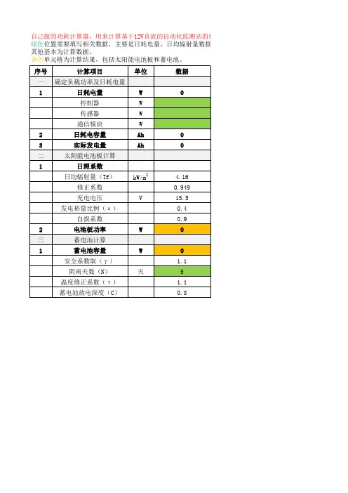
太阳能功耗计算器太阳能功耗计算器主要用于计算太阳能设备的功耗。
太阳能设备可以是太阳能光伏发电系统、太阳能热水器、太阳能空调等。
有了太阳能功耗计算器,用户可以通过输入设备的相关参数,如功率、工作时间等,快速准确地计算出设备的功耗。
同时,太阳能功耗计算器还可以提供更多的能源管理功能,例如提示用户设备是否超出额定功耗、节能建议等。
太阳能光伏发电系统是太阳能设备中最常见的一种,也是应用最广泛的一种。
太阳能光伏发电系统通过太阳能电池板将阳光转化为电能。
在计算太阳能光伏发电系统的功耗时,太阳能功耗计算器需要考虑太阳能电池板的额定功率以及太阳能电池板的工作时间。
用户只需要输入这些参数,太阳能功耗计算器就能够准确计算出光伏发电系统的功耗。
太阳能热水器也是一种常见的太阳能设备。
太阳能热水器通过太阳能集热器将阳光转化为热能,用于加热水。
计算太阳能热水器的功耗时,太阳能功耗计算器需要考虑太阳能集热器的额定功率以及太阳能集热器的工作时间。
用户只需要输入这些参数,太阳能功耗计算器就能够准确计算出热水器的功耗。
太阳能空调是利用太阳能供能的一种空调系统。
太阳能空调通过太阳能电池板将阳光转化为电能,然后用于空调系统的运行。
计算太阳能空调的功耗时,太阳能功耗计算器需要考虑太阳能电池板的额定功率以及空调系统的工作时间。
用户只需要输入这些参数,太阳能功耗计算器就能够准确计算出空调系统的功耗。
太阳能功耗计算器不仅可以帮助用户计算设备的功耗,还可以提供一些节能建议。
例如,太阳能功耗计算器可以根据设备的功耗情况,推荐用户节能减排的措施,如合理调整设备的工作时间、增加太阳能电池板的规模等。
这些节能建议可以帮助用户更好地管理和优化能源消耗,实现节能减排的目标。
总之,太阳能功耗计算器是一款方便、实用的工具,可以帮助用户快速准确地计算太阳能设备的功耗,并提供节能建议。
随着太阳能的应用越来越广泛,太阳能功耗计算器将在节能减排和能源管理方面发挥重要的作用。
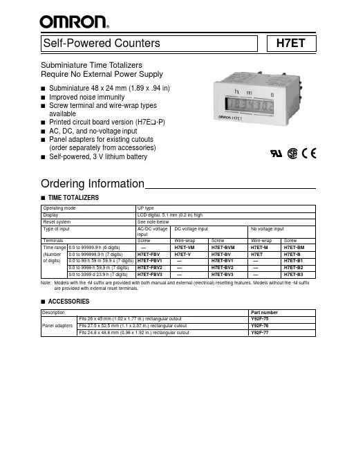
Subminiature Time TotalizersRequire No External Power Supplys Subminiature 48 x 24 mm (1.89 x .94 in)s Improved noise immunitys Screw terminal and wire-wrap types availables Printed circuit board version (H7E u -P)s AC, DC, and no-voltage inputs Panel adapters for existing cutouts (order separately from accessories)sSelf-powered, 3 V lithium batterySelf-Powered CountersH7ETOperating mode UP typeDisplayLCD digital, 5.1 mm (0.2 in) highReset system See note below Type of inputAC/DC voltage DC voltage input No voltage inputinputTerminals Screw Wire-wrap ScrewWire-wrap Screw Time range 0.0 to 99999.9 h (6 digits) —H7ET-VM H7ET-BVM H7ET-M H7ET-BM (Number 0.0 to 999999.9 h (7 digits)H7ET-FBV H7ET-V H7ET-BV H7ET H7ET-B of digits)0.0 to 99 h 59 m 59.9 s (7 digits)H7ET-FBV1 —H7ET-BV1 —H7ET-B10.0 to 9999 h 59.9 m (7 digits)H7ET-FBV2 —H7ET-BV2 —H7ET-B20.0 to 3999 d 23.9 h (7 digits)H7ET-FBV3 —H7ET-BV3—H7ET-B3Ordering Informations TIME TOTALIZERSDescription Part number Fits 26 x 45 mm (1.02 x 1.77 in.) rectangular cutout Y92F-75Panel adaptersFits 27.5 x 52.5 mm (1.1 x 2.07 in.) rectangular cutout Y92F-76Fits 24.8 x 48.8 mm (0.98 x 1.92 in.) rectangular cutoutY92F-77s ACCESSORIESNote:Models with the -M suffix are provided with both manual and external (electrical) resetting features. Models without the -M suffixare provided with external reset terminals.H7ET2Supply voltage Not required (powered by built-in battery)AC/DC voltage input:24 to 240 VAC ± 10%, 50/60 Hz, or6 to 240 VDC ± 10% at "High" (logic) level0 to 1.5 VAC ± 10%, 50/60 Hz, or0 to 2 VDC ± 10% at "Low" (logic) levelInput DC voltage input: 4.5 to 30 VDC at "High" (logic) level0 to 2 VDC at "Low" (logic) levelNo-voltage input:Maximum short-circuit impedance: 10 kΩ max.Short-circuit residual voltage: 0.5 V max.Minimum open impedance: 500 kΩ min.Reset time External and manual reset types (6-digit models): 20 ms reset signalExternal reset types (7-digit models): 20 ms reset signal* ON/OFF ratio 1:1s RATINGSTiming Charts CHARACTERISTICSInsulation resistance100 MΩ min. at 500 VDCDielectric strength1,000 VAC 50/60 Hz for 1 minute between current-carrying terminals and exposednon-current-carrying metal partsVibration Mechanical durability: 10 to 55 Hz; 0.75 mm (0.03 in) double amplitudeMalfunction durability: 10 to 55 Hz; 0.3 mm (0.02 in) double amplitudeShock Mechanical durability: Approx. 30 GMalfunction durability: Approx. 10 GAmbient temperature Operating: -10° to 55°C (14° to 131°F)Storage: -25° to 65°C (-13° to 149°F)Humidity Operating: 35 to 85% RHBattery life10 years min. of continuous operationWeight AC/DC voltage input type: Approx. 90 g (3.18 oz) including mounting bracketDC voltage and No-voltage input types: Approx. 60 g (2.12 oz) including mounting bracket Approved by the following standardsULCSACE (EMC)Specifications3H7ET+0.5 -045+0.5 -0DimensionsUnit: mm(inch)s s WIRE-WRAP TERMINAL COUNTERSPanel cutout2.5113013224M3.5 screw terminal222.511112.5518.52.5448 (1.89)48.9(1.93)78.9(3.11)22.2(0.87+0.02 -0 )(1.77Mounting bracket 8 mm Mounting nutM4 Mounting post44.8(1.76)45(1.77+0.02-0 )48 (1.89)44.8(1.76)Mounting holes and footprint37 (1.46)44.8(1.76)+0.5 -045(1.77+0.02-0 )(0.94)33 (1.30)M4 Mounting post8 mm Mounting nutMounting bracket Mounting bracket 48 (1.89)24(0.94)5-dia. mounting holeFour 5-dia. terminal hole24(0.94)H7ET4sPANEL MOUNTING ADAPTERSY92F-77Y92F-75Two 3.5 mm dia. mounting holes22.224.245.248.26348.245.23824.222.24.5 mm dia. mounting holeY92F-76427.52-M452.5(2.07)442-M3Connectionss AC/DC VOLTAGE INPUT TYPE1.Contact input (voltage input through a relay or switchcontact)2.Solid-state input (open collector input of an NPN transistor)Panel cutoutPanel cutoutPanel cutoutTerminals (2) and (4)are internally insulated.Terminals (2) and (4)are internally insulated.264563(2.48)31(1.22)72 (2.83)48.8(1.92)28.8(1.13) 60 (2.36)50(1.97) 53.8 (2.12)26(1.02)38(1.50)24.8(0.98)48.2 45.2 24.222.2h o u r sh o u r sh o u r sH 7E TH 7E TH 7E T5H7ETs DC VOLTAGE INPUT TYPE1.Contact input (voltage input through a relay or switchcontact)2.Solid-state input (open collector input of an NPNtransistor)s NO-VOLTAGE INPUT TYPE1.Contact input (input by a relay or switch contact)2.Solid-state input (open collector input of an NPNtransistorOperationss SELECTING THE H7ET TOTALIZING COUNTERDetermine the maximum counting speed of the counter by evaluating the input conditions listed in the table at right.Counting speed 20 or 30 cps 1 kcpsContact Relay or switch Do not input contact signal inputcontact input with signal inputs.some chattering.Chattering is counted as signal input.Solid-state Low-speedHigh-speed transistor signal inputtransistor inputsinputss INPUT VERIFICATION WITH THE H7ET TIME COUNTERThe decimal point on models with 0.1 hour and 0.1 minute displays blinks every other second while an input signal is being applied. If the decimal point is not blinking, the input signal is not being received correctly. Check the input signal connections.For models with 0.1 second displays, the decimal point does not blink. The input signal causes the right-most digit to increment frequently enough to observe whether or not the input signal is being received correctly. If the display does not increment, the input signal is not being received.Terminals (2) and (4)are internally connected.Terminals (2) and (4)are internally connected.Terminals (2) and (4)are internally connected.ResetTerminals (2) and (4)are internally connected.InputResetH7ET-VH7ET6Installationhourss MANUALLY RESETTING COUNTERS(-M SUFFIX MODELS)The terminals used on H7E wire-wrap models have a crosssectional dimension of 1 x 1 mm. Select one of the threegauges of wire from the table at right. Also listed in the tableare the appropriate wiring hardware.If the input wiring must be routed together with the power lines,keep the length of that portion of wire running parallel with thepower lines to within 20 m (65.6 feet).When using shielded wire, stray capacitance may occur. Theoperation of the counter might be affected when using wireswhich have a capacitance which exceeds 500 pF (about 10 m,32.8 feet, with parallel wires of 2 mm2). Keep all wires as shortas possible.On some H7E models, the power input terminal and thecommon signal input terminal (terminals 2 and 4) are internallyshort-circuited. Pay special attention to polarity when wiringthese terminals.Keep the input wiring as short as possible.Whenever possible, avoid routing the input wiring of the AC/DCvoltage input type in parallel with 200 to 240 VAC power lines.s CAUTIONS CONCERNING THE H7ET TIME COUNTERs HOW TO MOUNT THE COUNTERInsert the H7E counter from the front of the mounting panel.Slide the mounting bracket into place from the rear of thepanel, and tighten the knurled nut by hand. Do not use tools(such as pliers) to tighten the nut. Excessive tightening maydamage the counter. Wire-wrap terminal models may be back-mounted, by soldering the terminals to a printed circuit board.Wire gauge Bit Sleeve MethodAWG22 2-A 2-B Normal wire-wrapAWG24 1-A 1-B Normal wire-wrapAWG26 3-A 3-B Normal wire-wrapsWIRE-WRAP TERMINALSCounters with "-M" suffixes offer the option of manual or externalresetting. To manually reset the counter, press the reset buttonlocated to the left of the display window. To prevent an accidentalreset, lock the reset button by sliding the button downward, withoutdepressing it. A small "click" sound may be heard, both whenlocking and unlocking the reset button. Slide the button up tounlock.H7ETOmron Europe B.V. EMA-ISD, tel:+31 23 5681390, fax:+31 23 5681397, /emaCat. No. GC CN4A 6/98/26M Specifications subject to change without notic e. P。
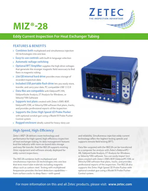
MIZ®-28FEATURES & BENEFITSCombines both multiplexed and simultaneous injection(SI) technologies into one boxEasy-to-use controls with built-in language selectionAutomatic voltage switchingOptional RFT Amplifier supplies the high drive voltagesthat generate the stronger magnetic field necessary to findflaws in magnetic tubing256 GB internal hard drive provides mass storage ofrecorded inspection dataIncluded USB portable flash drive lets you easily store,transfer, and carry your data. PC compatible USB 1.1/2.0Data files are compatible with EddynetPC/AN,EddynetSuite Analysis, ET Analysis for Windows, orVelocity®/AN SoftwareSupports test plans created with Zetec’s EIMS-BOP,EddynetPC/DM, or Velocity/DM software that plans, tracks,and provides professional reports of the inspectionSupports the Zetec High Speed 3D Probe Pusherwith optional conduit gun using a Model III Probe PusherControl systemRugged enclosure ideally suited for heavy-duty useHigh-Speed, High-EfficiencyZetec’s MIZ®-28 delivers more technology and performance for high-speed, high-efficiency inspection of heat exchanger tubing. Its data management features lead the industry with more on-board data storage and easy file transfer. And the MIZ-28 supports existing Zetec equipment and software already deployed for eddy current inspections.The MIZ-28 combines both multiplexed and simultaneous injection (SI) technologies into one box that tests most tube materials including magnetic alloys such as carbon steel. Testing with multiplexed frequencies provides the best detection capabilities—from surface cracks to deep flaws—with speed and reliability. Simultaneous injection eddy current technology offers the highest testing speeds and supports remote field testing (RFT).Data files acquired with the MIZ-28 can be transferred to a computer for analysis with Zetec’s EddynetPC/AN, EddynetSuite Analysis, ET Analysis for Windows, or Velocity®/AN software. You can easily import test plans created with Zetec’s EIMS-BOP, EddynetPC/DM, or Velocity/DM software that plans, tracks, and provides professional reports of the inspection. The MIZ-28 also supports the Zetec High Speed 3D Probe Pusher with optional conduit gun using a Model III Probe Pusher Control system. Zetec, Inc.8226 Bracken Pl. SE | Suite 100Snoqualmie, WA 98065Toll Free: 800.643.1771P: 425.974.2700All the information herein is subject to change without prior notification. ZDS0208 Rev C.The MIZ-28 imports an inspection Test Plan and displays it for the operator.Zetec’s Velocity/DM is inspection management software for organizing, tracking, and creating reports of eddy current inspection.。


太阳能发电系统计算器太阳能发电系统计算器是一种工具,用于帮助人们计算和评估他们所需要的太阳能发电系统的规模和成本。
太阳能发电系统是一种可再生能源发电方式,通过将太阳能转化为电能来供应家庭或商业需求。
使用太阳能发电系统可以减少对传统能源的依赖,降低能源成本,并对环境产生更少的污染。
1.地理位置和天气数据输入:用户首先需要提供他们的地理位置信息,例如经纬度或所在城市名称。
这些数据将用于估算当地的太阳能辐射水平,从而影响系统的发电能力。
一些太阳能发电系统计算器还可以获取实时的天气数据,以更好地预测系统的发电模式。
2.电量需求估算:用户需要提供他们家庭或商业的电量需求,例如每月或每年的电费账单或电力使用情况。
这些数据将用于估算所需的系统容量,以满足用户的用电需求。
3.系统容量计算:根据用户提供的电量需求和地理位置数据,太阳能发电系统计算器将估算所需的系统容量。
这通常以千瓦(KW)为单位表示,并决定了所需的太阳能电池板数量和额定功率。
4.太阳能电池板数量和布局:太阳能发电系统计算器将根据用户提供的系统容量和可用的安装面积,计算所需的太阳能电池板数量和布局。
通常,太阳能电池板是安装在屋顶或地面上,以最大化太阳能的吸收。
5.系统成本估算:太阳能发电系统计算器可以根据用户预算和市场价格,估算所需系统的成本。
这包括太阳能电池板、逆变器、电池储能系统(可选)、安装服务和维护费用等方面的成本。
6.发电效益和投资回报期计算:太阳能发电系统计算器可以估算用户的发电效益和投资回报期。
发电效益是指系统在使用寿命内生成的电能量,相对于传统能源的成本节约。
投资回报期是指实际成本与节约成本之间的时间间隔,通常以年为单位。
7.可视化和报告生成:太阳能发电系统计算器通常会生成可视化的图表和报告,以便用户更好地理解和评估系统的规模和成本。
这些图表和报告可以显示系统容量、电池板布局、发电效益、投资回报期等关键指标。
总之,太阳能发电系统计算器是一种用于计算和评估太阳能发电系统的工具,可以帮助用户确定系统的规模、成本和发电效益,从而实现更可持续、经济和环保的能源供应。


energy star intel设定Energy Star(能源之星)是一个由美国环境保护署(EPA)和能源部(DOE)联合推行的计划,旨在通过提供能源效率标准和认证,促进节能产品和做法的发展。
许多电子设备,如计算机、显示器、服务器、数据存储设备等,都可以通过符合Energy Star的标准来获得认证,并因此被认为是能源效率较高的产品。
在涉及Intel(英特尔)的产品中,如台式机主板,用户可以通过特定的设置来确保其系统符合Energy Star的要求。
下面将详细介绍如何在Intel平台上进行Energy Star的设定。
前提条件•确保你的系统使用的是Intel台式机主板。
•了解你的主板型号和相应的BIOS/UEFI设置。
设置步骤进入BIOS/UEFI设置:•在系统启动时,通常会有提示按某个键(如F2、Del等)进入BIOS/UEFI设置。
根据屏幕上的提示,在适当的时间按下相应的键。
•如果系统未显示提示,你可能需要在启动过程中多次尝试按下常见的BIOS/UEFI进入键,或者查阅你的主板手册以获取准确的信息。
导航至电源管理设置:•在BIOS/UEFI界面中,使用键盘上的方向键导航至“电源管理”或类似的选项。
•在这里,你应该能够找到与节能和电源效率相关的各种设置。
配置Energy Star相关选项:•查找与Energy Star相关的特定设置。
这些设置可能包括休眠状态配置、电源恢复选项、节能模式等。
•根据你的需求和Energy Star的标准,调整这些设置。
例如,你可能需要启用S0、S3等休眠状态,并确保系统在休眠时能够高效地恢复。
•请注意,某些设置可能需要你具备一定的技术知识,以确保不会意外地影响系统的稳定性和性能。
保存并退出:•在完成所有必要的设置后,选择“保存并退出”选项。
•系统可能会提示你确认更改,并重新启动以应用新的设置。
注意事项•确保在更改任何BIOS/UEFI设置之前备份你的重要数据,以防万一出现问题。
SebaKMT · Dr.-Herbert-Iann-Str. 6 · 96148 Baunach/Germany · Tel. +49(0)9544 - 680 Fax +49(0)9544 - 2273·*****************· ISO 9001:2000T echnical data subject to change without notice.LFT_OWTS M 28_eng_2007_05sebaKMTisaregisteredtrademarkofthesebaKMTgroupOWTS M 28Partial discharge Test and Fault Location SystemBenefi tsPD Measurement by means of DAC similar to nominal net frequencyOnline processing for complex PD-Diagnosis Portable test system, compact design and low weightIntegrated tan δ- measurementDescriptionThe oscillating wave test system OWTS is used to identify, evaluate and locate partial discharge (PD) faults in a cable insulation and accessories in all types of medium voltage cables.The system consists of a notebook as a WLAN control unit and a HV unit. The HV unit contains a HV source and a resonance inductor with an integrated electronic switch to generate the AC test voltage. The HV divider and an embed-ded controller for the digital data acquisition and PD signal processing is integrated. The storage, analysis and evaluation of the PD signals takes place in the notebook and can be done either on site or in the offi ce. The PD fault location is based on the time domain refl ection method.For the PD diagnosis the test object is charged to the pre-selected peak value by a HV source within a couple of seconds and afterwards shorted with an electronic switch via a resonance coil. Thus a sinusoidal oscillating AC voltage with low damping is created (DAC). The frequency is fi xed in a range from 50 Hz to several 100 Hz, depending on thecapacitance of the test object.Since the frequency of the test voltage is close to nominal service conditions, all measured PD activities can be effec-tively evaluated.The oscillating voltage energizes the test object only for a few 100 ms and therefore cause no long-term infl uences.The PD extinction voltage and the tan δ-value can be easily determined due to the decaying amplitude of the test voltage. Critical PD levels responsible for the future status of the cable insulation are an important criteria in the evaluation.The analysis and evaluation of the typical PD parameter as well as the PD fault location supports the Asset Management for reliable decision criteria for maintenance- or replacement activities.FeaturesPD diagnosis by means of damped AC voltage (DAC)PD level measurement according to IEC 60270Automatic adjustment of the bandwidth of themeasurement circuit for optimised signal detectionAutomatic calibration mode with joint location featurePC with WIN XP and WLAN for system controlStatistical PD fault acquisition, online processingMenu-driven unit to operate the test sequencePortable design, low weight, easy set-up on-siteScope of deliveryHV unitNotebook with WLAN connection to the HV unitSafety-Box with HV ON/OFF; Emergency push button and key switchAccessory bagOperating manual5 m HV test lead; power supply- and grounding cableOWTS Explorer package, 2 Dongle CD-ROMCalibratorTechnical DataM ax. DAC output-voltage28 kVpeak / 20 kVrmsDAC frequency range50 Hz … 800 HzCapacitance range0,025 µF … 2 µFHV charging current10 mAPD measuring range 1 pC … 100 nCPD level detection acc. to IEC 60270Bandwidth for PD-localisation150 kHz … 45 MHzDissipation factor tan δ0,1 % … 10 %Power supply110 … 240 V-AC, 50 … 60 Hz Operating temperature-10 °C … +40 °CWeight app. 55 kgComponentsUnit 1Ø: 600 mm, H: 650 mmUnit 2Notebook app. 2 kg1981。
用户组态手册目录用户组态手册 (I)第一部分快速组态入门 (1)1.软件应用流程 (1)1.1HOLLiAS MACS系统软件组态工作流程框图 (1)1.2框图说明 (1)2.系统软件组态操作步骤说明 (4)2.1组态前期准备工作 (4)2.2新建工程 (8)2.3控制站/模块/点组态操作步骤 (11)2.4控制逻辑组态操作步骤 (16)2.5网络变量组态步骤 (24)2.6工艺流程图组态操作步骤 (27)2.7参数汇总组态操作步骤 (32)2.8控制画面组态操作步骤 (35)2.9趋势组定义操作步骤 (39)2.10总貌画面组态操作步骤 (42)2.11事件组态操作步骤 (45)2.12操作员站组态操作步骤 (47)2.13系统设置操作步骤 (49)2.14键盘定义操作步骤 (51)2.15用户组态操作步骤 (53)2.16高级报警组态操作步骤 (54)2.17磁盘变量组态操作步骤 (55)2.18配方管理操作步骤 (56)2.19通讯向导操作步骤 (62)2.20报警设置操作步骤 (66)2.21语言设置操作步骤 (67)2.22系统软件组态保存与编译操作步骤 (68)2.23报表组态操作步骤 (69)2.24系统软件组态下装操作步骤 (77)第二部分详细组态说明 (1)第一章系统概述 (1)1.1系统构成 (1)1.2.1网络结构 (2)1.2.2系统组成 (4)1.2系统功能 (5)1.3系统特点 (6)第二章系统软件安装 (8)2.1软件安装运行环境 (8)2.2系统软件安装步骤 (8)第三章工程管理器总述 (14)3.1界面总貌 (14)3.2组态树基本操作 (16)3.3菜单命令 (16)第四章创建工程 (19)4.1功能说明 (19)4.1.1新建工程 (19)4.1.2打开工程 (23)4.1.3备份工程 (25)4.1.4关闭工程 (28)4.1.5删除工程 (29)4.1.6恢复工程 (30)4.1.7工程属性 (33)4.2创建工程组态实例 (35)第五章控制站I/O组态 (40)5.1控制站 (40)5.1.1主控型号及功能 (40)5.1.1.1 FM系列主控 (40)5.1.1.2 SM系列主控 (41)5.1.2控制站组态 (41)5.1.2.1 新增控制站 (42)5.1.2.2 组态信息查询 (44)5.1.2.3 机柜布置 (45)5.1.2.4 编译控制站 (52)5.1.2.5 删除控制站 (53)5.1.2.6 其它信息 (54)5.2I/O模块 (56)5.2.1模块型号及功能 (56)5.2.1.1 FM系列模块 (56)5.2.1.2 SM系列模块 (59)5.2.2I/O模块组态 (61)5.2.2.1 新增模块 (61)5.2.2.2 模块地址修改 (63)5.2.2.3 冗余模块添加 (65)5.2.2.4 模块信息查询 (67)5.2.2.5 安装位置修改 (69)5.2.2.6 删除模块 (73)5.3功能模块 (73)5.3.1通讯模块 (74)5.3.1.1 模块型号及功能 (74)5.3.1.2 通讯模块组态 (75)5.4第三方DP设备 (92)5.5点 (93)5.5.1I/O点 (93)5.5.1.1 I/O点信息详解 (93)5.5.1.2 I/O点组态 (105)5.5.2中间点 (113)5.5.2.1 中间点信息详解 (113)5.5.2.2 中间点组态 (134)5.5.3通讯点 (134)5.5.4查找测点 (136)5.6网络变量定义 (137)5.7导入测点清单 (140)5.7.1测点清单信息详解 (140)5.7.1.1 测点清单中CONTROL表 (141)5.7.1.2 测点清单中MODULE表 (141)5.7.1.3 测点清单中AI点 (142)5.7.1.4 测点清单中RTD点 (143)5.7.1.5 测点清单中TC点 (144)5.7.1.6 测点清单中PI点 (145)5.7.1.7 测点清单中AO点 (146)5.7.1.8 测点清单中DI点 (147)5.7.1.9 测点清单中DO点 (148)5.7.1.10 测点清单中SOE点 (148)5.7.1.11 测点清单中DEH点 (149)5.7.1.12 测点清单中DPTAG点 (149)5.7.2导入测点清单 (150)5.7.3导出测点清单 (151)5.8用户自定义库 (152)5.8.1新建用户库 (152)5.8.2刷新用户库索引 (154)5.8.3删除用户库 (154)5.8.4重命名用户库 (155)5.9控制站I/O组态实例 (156)5.9.1新建控制站 (156)5.9.2添加I/O模块和I/O点 (156)5.9.3添加通讯模块和通讯点 (163)5.9.4定义网络变量 (173)5.9.5导入测点清单 (176)5.9.6编译 (178)5.9.7中间点编辑 (178)第六章操作员站组态 (180)6.1功能说明 (180)6.1.1操作员站/工程师站 (180)6.1.2操作员站名 (180)6.1.3IP地址 (181)6.1.4主/从历史站 (181)6.1.5时间服务器 (181)6.1.6事件 (181)6.2组态操作说明 (181)6.2.1新增操作员站 (182)6.2.2组态操作员站 (183)6.2.3删除操作员站 (185)6.2.4下装操作员站 (186)6.3操作员站组态实例 (186)第七章控制逻辑组态 (192)7.1控制逻辑总述 (192)7.2控制逻辑组态界面 (193)7.2.1标题栏 (193)7.2.2菜单栏 (194)7.2.2.1 文件菜单 (194)7.2.2.2 编辑菜单 (195)7.2.2.3 工程菜单 (199)7.2.2.4 插入菜单 (204)7.2.2.5 其他菜单 (204)7.2.2.6 在线菜单 (205)7.2.2.7 窗口菜单 (210)7.2.2.8 帮助菜单 (213)7.2.3工具栏 (213)7.2.4树型结构窗口 (214)7.2.4.1 POUs (214)7.2.4.2 资源 (214)7.2.5工作区 (224)7.2.5.1 局部变量声明区 (224)7.2.5.2 程序编辑区 (224)7.2.6编译窗口 (225)7.3控制逻辑组态操作说明 (226)7.3.1点生成 (226)7.3.2POU语言 (229)7.3.2.1 CFC (229)7.3.2.2 FBD (240)7.3.2.3 LD (247)7.3.2.4 ST (254)7.3.2.5 SFC (261)7.3.2.6 IL (271)7.3.3创建/添加程序 (278)7.3.4创建/添加功能块 (279)7.3.5创建/添加函数 (280)7.3.6控制逻辑算法编写 (281)7.3.6.1 变量的数据类型 (281)7.3.6.2 关于变量的有效范围 (284)7.3.6.3 变量的属性 (285)7.3.6.4 量程转换 (285)7.3.6.5 算法介绍 (290)7.3.7编译、登录及调试 (302)7.3.7.1 编译 (302)7.3.7.2 登录 (302)7.3.7.3 在线调试 (303)7.4控制逻辑组态实例 (308)第八章图形组态 (317)8.1工艺流程图 (317)8.1.1功能说明 (317)8.1.2组态操作说明 (317)8.1.2.1 流程图页面管理 (319)8.1.2.2 静态对象制作 (327)8.1.2.3 动态对象制作 (333)8.1.2.4 导入图形文件 (363)8.1.2.5 编译图形 (367)8.2参数汇总 (367)8.2.1功能说明 (367)8.2.2组态操作说明 (368)8.3控制画面 (373)8.3.1功能说明 (373)8.3.2组态操作说明 (373)8.4趋势组定义 (378)8.4.1功能说明 (378)8.4.2组态操作说明 (378)8.5总貌画面 (381)8.5.1功能说明 (381)8.5.2组态操作说明 (382)8.6图形组态实例 (387)8.6.1新建工艺流程图 (387)8.6.2新建参数组 (389)8.6.3新建控制组 (391)8.6.4新建趋势组 (393)8.6.5新建总貌画面 (395)8.6.6在线运行画面 (401)第九章系统组态 (404)9.1系统设置 (404)9.1.1功能说明 (404)9.1.2组态操作说明 (404)9.1.2.1 图形设置 (405)9.1.2.2 校时设置 (407)9.1.2.3 权限设置 (408)9.2用户组态 (408)9.2.1功能说明 (408)9.2.2组态操作说明 (410)9.3键盘定义 (414)9.3.1功能说明 (414)9.3.2组态操作说明 (415)9.3.2.1 多区域键盘 (419)9.4事件组态 (422)9.4.1功能说明 (422)9.4.2组态操作说明 (425)9.5高级报警 (427)9.5.1功能说明 (427)9.5.2组态操作说明 (428)9.6磁盘变量 (430)9.6.1功能说明 (431)9.6.2组态操作说明 (432)9.7配方管理 (438)9.7.1功能说明 (438)9.7.2组态操作说明 (438)9.8通讯向导 (442)9.8.1功能说明 (442)9.8.2组态操作说明 (444)9.8.2.1 新建通讯设备 (445)9.8.2.2 修改通讯参数 (450)9.9报警设置 (452)9.9.1功能说明 (452)9.9.2组态操作说明 (452)9.10语言设置 (454)9.11系统组态实例 (456)9.11.1系统设置 (456)9.11.2用户组态 (457)9.11.3键盘定义组态 (459)9.11.4事件组态 (461)9.11.5高级报警组态 (462)9.11.6磁盘变量组态 (463)9.11.7配方管理组态 (465)9.11.8通讯向导组态 (472)9.11.9报警设置组态 (477)9.11.10语言设置组态 (479)第十章编译和下装 (481)10.1编译部分 (481)10.1.1编译 (481)10.1.2编译控制站 (482)10.1.2.1 编译当前控制站 (483)10.1.2.2 编译全部控制站 (483)10.1.3编译图形 (484)10.2下装部分 (484)第十一章报表组态 (488)11.1功能说明 (488)11.2组态操作说明 (488)11.2.1删除报表 (495)11.2.2报表重命名 (496)11.3组态实例 (496)第十二章代码编辑 (505)12.1新建代码 (506)12.2重命名代码文件 (507)12.3删除代码文件 (508)12.4查找用户函数 (508)第十三章CAD接线图 (511)13.1功能说明 (511)13.2组态操作说明 (515)13.3组态实例 (516)第十四章仿真控制器 (521)14.1功能说明 (521)14.2操作说明 (522)14.2.1控制站信息 (526)14.2.2控制站总览 (527)14.2.3控制站批量设置 (529)第十五章HART设备管理器 (530)15.1界面说明 (530)15.1.1启动HART设备管理器 (530)15.1.2工程视图的显示方式 (534)15.1.3设备管理 (537)15.1.3.1 常规设备管理 (537)15.1.3.2 智能设备管理 (537)15.1.4设备信息汇总 (539)15.1.5退出连接 (540)15.2服务器端各功能说明 (541)15.2.1HART仪表信息功能 (541)15.2.1.1 基本信息 (541)15.2.1.2 通用信息 (541)15.2.1.3 主变量信息 (542)15.2.1.4 副变量信息 (544)15.2.1.5 调试信息 (544)15.2.2用户管理功能 (545)15.2.3日志功能 (547)15.2.4仪表台帐信息功能 (548)15.2.4.1 查看仪表台帐信息 (548)15.2.4.2 仪表筛选 (548)15.2.4.3 台帐信息保存和打开 (548)15.2.5仪表维护功能 (549)15.2.5.1 查看仪表维护信息 (549)15.2.5.2 维护信息的预览打印 (549)15.2.6其它功能 (550)15.2.6.1 模件参数 (550)15.2.6.2 单位显示 (550)15.3客户端功能说明 (550)15.3.1启动客户端 (550)15.3.2显示界面 (551)15.3.3添加服务器 (551)15.3.3.1 服务器IP设置 (552)15.3.3.2 添加多个服务器 (552)15.3.4连接服务器 (552)15.3.5查看设备信息 (553)15.3.6断开服务器 (554)15.3.7删除服务器 (554)15.3.8仪表维护功能 (555)15.4错误信息 (555)第十六章多语言的使用 (556)第三部分速查手册 (559)1.数学及逻辑运算库HS_MathLogic.lib (559)1.1流量积算 (559)1.2折线函数 (561)1.3优先级递减多重比较器 (563)1.4D触发器 (565)1.5开关量变态次数累积 (566)1.6下降沿触发 (567)1.7开关量状态时间累积器 (567)1.8幂函数 (569)1.9数值滤波 (569)1.10一维插值 (571)1.11多项式 (572)1.12限定或 (573)1.14定义模拟量越限时间累计器 (576)1.15计算变化率 (577)1.16二维插值 (579)1.17上升沿触发 (581)2.时域运算库HS_TimeField.lib (582)2.1设定曲线 (582)2.2微分(不完全微分) (584)2.3一阶惯性 (585)2.4一阶滞后补偿 (586)2.5积分 (588)2.6超前滞后 (590)2.7滞后比较 (591)2.8斜坡函数 (592)2.9二阶惯性 (593)2.10二阶滞后补偿 (595)2.11定时器 (597)2.12一阶纯滞后 (601)2.13二阶纯滞后 (603)2.14三阶纯滞后 (604)3.控制算法库HS_Ctrol.lib (606)3.1手操器 (606)3.2组合伺服放大(HSCSLAVE) (610)3.3组合伺放(HSCSLAVE5) (612)3.4开关手操器 (616)3.5断路器 (617)3.6断路器2 (622)3.7断路器5 (628)3.8PID (636)3.9顺控设备(HSSCS) (644)3.10伺服放大 (652)3.11调节门(HSVALVE) (653)3.12远程调节门(HSVALVE5) (655)4.报警限制选择算法HS_AlmLimSec.lib (658)4.1冗余选择信号输入 (658)4.2模入信号二选一 (659)4.3报警闪光 (662)4.4幅值报警 (663)4.5偏差报警 (666)4.6速率报警 (667)4.7数字开关 (668)4.8幅值限制 (669)4.9速率限制 (670)4.10三取中 (671)5.专用算法HS_Special.lib (677)5.1模拟存储 (677)5.2双输出平衡(双平衡) (679)5.3断路器灯光 (682)5.4层选 (683)5.5步参数赋值 (685)5.6脉冲定位器 (687)5.7首出记忆(八输入) (689)5.8首出记忆(十六输入) (690)5.9首出记忆(三十二输入) (692)5.10闪光 (696)6.IEC运算符 (699)6.1算术运算符 (699)6.2位串运算符 (702)6.3移位运算符 (704)6.4选择运算符 (707)6.5比较运算符 (709)6.6地址运算符 (711)6.7调用运算符 (712)6.8数据类型转换运算符 (712)6.9数字运算符 (717)7.标准库(Standard.lib)功能块 (723)7.1字符串函数 (723)7.2双稳态功能块 (726)7.3触发器 (728)7.4计数器 (729)7.5计时器 (732)8.应用库(Util.lib)功能块 (735)8.1BCD转换 (735)8.2位/字节函数 (735)8.3数学帮助函数 (736)8.4控制器 (738)8.5信号发生器 (739)8.6函数操纵器 (741)8.7模拟值处理 (742)二、数据库点项名列表 (744)三、控制逻辑中的编译错误和警告信息 (760)编译错误信息(Error) (760)3100 (760)3101 (760)3110 (760)3111 (760)3112 (760)3114 (761)3115 (761)3116 (761)3120 (761)3121 (761)3122 (761)3123 (762)3130 (762)3131 (762)3132 (762)3150 (762)3160 (762)3161 (763)3162 (763)3163 (763)3200 (763)3201 (763)3202 (763)3203 (764)3204 (764)3205 (764)3206 (764)3207 (764)3208 (764)3209 (764)3210 (765)3211 (765)3212 (765)3250 (765)3251 (765)3252 (765)3253 (766)3254 (766)3255 (766)3400 (766)3401 (766)3402 (766)3403 (766)3404 (767)3405 (767)3406 (767)3407 (767)3408 (767)3410 (768)3411 (768)3412 (768)3413 (768)3414 (768)3415 (768)3450 (768)3451 (769)3452 (769)3453 (769)3454 (769)3455 (769)3456 (769)3457 (770)3458 (770)3459 (770)3460 (770)3461 (770)3462 (770)3463 (770)3464 (771)3465 (771)3466 (771)3468 (771)3500 (771)3501 (771)3502 (772)3503 (772)3504 (772)3505 (772)3506 (772)3507 (772)3550 (773)3551 (773)3552 (773)3553 (773)3554 (773)3555 (773)3556 (774)3557 (774)3558 (774)3559 (774)3560 (774)3562 (775)3563 (775)3564 (775)3565 (775)3566 (775)3567 (775)3568 (776)3569 (776)3570 (776)3571 (776)3600 (776)3601 (776)3610 (777)3611 (777)3612 (777)3613 (777)3614 (777)3615 (777)3616 (777)3617 (778)3618 (778)3619 (778)3620 (778)3700 (778)3701 (778)3702 (779)3703 (779)3704 (779)3705 (779)3720 (779)3721 (779)3722 (780)3726 (780)3727 (780)3728 (780)3729 (780)3740 (780)3741 (781)3742 (781)3743 (781)3744 (781)3745 (781)3746 (781)3748 (782)3749 (782)3750 (782)3751 (782)3760 (782)3761 (782)3780 (783)3781 (783)3782 (783)3783 (783)3784 (783)3800 (783)3801 (784)3802 (784)3803 (784)3820 (784)3821 (784)3840 (784)3841 (785)3900 (785)3901 (785)3902 (785)3903 (785)3904 (785)3905 (786)3906 (786)3907 (786)3908 (786)4000 (786)4001 (786)4010 (786)4011 (787)4012 (787)4013 (787)4014 (787)4015 (787)4016 (788)4017 (788)4020 (788)4021 (788)4022 (788)4023 (788)4024 (788)4026 (789)4027 (789)4028 (789)4029 (789)4030 (789)4031 (790)4032 (790)4033 (790)4034 (790)4035 (790)4040 (790)4041 (791)4042 (791)4043 (791)4050 (791)4051 (791)4052 (791)4053 (791)4054 (792)4060 (792)4061 (792)4062 (792)4063 (792)4064 (792)4070 (793)4071 (793)4072 (793)4100 (793)4110 (793)4111 (793)4112 (794)4113 (794)4114 (794)4120 (794)4121 (794)4122 (794)4200 (795)4201 (795)4202 (795)4203 (795)4204 (795)4205 (795)4206 (796)4208 (796)4209 (796)4210 (796)4211 (796)4212 (796)4213 (797)4250 (797)4251 (797)4252 (797)4253 (797)4254 (797)4255 (798)4256 (798)4257 (798)4258 (798)4259 (798)4260 (798)4261 (799)4262 (799)4263 (799)4264 (799)4265 (799)4266 (799)4267 (799)4268 (800)4269 (800)4270 (800)4271 (800)4272 (800)4273 (800)4274 (801)4300 (801)4301 (801)4302 (801)4303 (801)4320 (801)4321 (801)4330 (802)4331 (802)4332 (802)4333 (802)4334 (802)4335 (802)4337 (803)4338 (803)4339 (803)4340 (803)4341 (803)4342 (803)4343 (804)4344 (804)4345 (804)4346 (804)4347 (804)4350 (804)4351 (805)4352 (805)4353 (805)4354 (805)4355 (805)4356 (805)4357 (805)4358 (806)4359 (806)4360 (806)4361 (806)4362 (806)4363 (806)4364 (807)4365 (807)4366 (807)4367 (807)4368 (807)4369 (807)4370 (807)4371 (808)4372 (808)4373 (808)4374 (808)4375 (808)4376 (808)4377 (809)4400 (809)4401 (809)4402 (809)4403 (809)4405 (809)4406 (810)4407 (810)4408 (810)4409 (810)4410 (810)4411 (810)4412 (811)4413 (811)4414 (811)4415 (811)4416 (811)4417 (811)4418 (811)4419 (812)4420 (812)4421 (812)4422 (812)4423 (812)4424 (812)4425 (813)4426 (813)4427 (813)4428 (813)4429 (813)4430 (813)4431 (813)4432 (814)4434 (814)4435 (814)4436 (814)4437 (814)4438 (814)4500 (815)4501 (815)4520 (815)4521 (815)4522 (815)4523 (815)4550 (815)4551 (816)4552 (816)4553 (816)4555 (816)4556 (816)4557 (817)4558 (817)4560 (817)4561 (817)4562 (817)4563 (817)4564 (818)4565 (818)4566 (818)4600 (818)4651 (818)4670 (818)4671 (819)4685 (819)4686 (819)4700 (819)4701 (819)4702 (819)4703 (820)4704 (820)4900 (820)编译警告信息(Warning) (821)1100 (821)1101 (821)1102 (821)1103 (821)1200 (821)1300 (821)1301 (822)1302 (822)1400 (822)1401 (822)1410 (822)1411 (822)1412 (823)1413 (823)1500 (823)1501 (823)1502 (823)1503 (824)1504 (824)1506 (824)1507 (825)1550 (825)1700 (825)1800 (825)1801 (825)1802 (825)1803 (826)1804 (826)1805 (826)1806 (826)1900 (826)1901 (826)1902 (827)1903 (827)1904 (827)1970 (827)四、模块端子接线图 (828)FM系列模块 (828)FM141 (828)FM142 (829)FM143 (830)FM143A (831)FM143E (832)FM143G (833)FM144 (834)FM144A (835)FM145 (836)FM147 (837)FM147A (838)FM147E (839)FM148 (840)FM148A (841)FM148C (842)FM148E (843)FM148F (844)FM148G (845)FM148R (846)接端子板FM133 (846)接端子板FM134 (847)FM151 (848)FM151A (849)FM151AR (850)FM151R (851)FM152 (852)FM152A (853)FM161 (854)接端子板FM131A(D) (854)接端子板FM136(A_1L) (855)接端子板FM136(A_2L) (856)接端子板FM136(P_2L) (857)接端子板FM136-DCR (858)FM161-SOE (859)FM161-48 (860)接端子板FM131A(D) (860)接端子板FM136(A_1L) (861)接端子板FM136(A_2L) (862)接端子板FM136(P_2L) (863)接端子板FM136-DCR (864)FM161-48-SOE (865)FM161D (866)接端子板FM131A(D) (866)接端子板FM136(A_1L) (867)接端子板FM136(A_2L) (868)接端子板FM136(P_2L) (869)接端子板FM136-DCR (870)FM161D-SOE (871)FM161D-48 (872)接端子板FM131A(D) (872)接端子板FM136(A_1L) (873)接端子板FM136(A_2L) (874)接端子板FM136(P_2L) (875)接端子板FM136-DCR (876)FM161D-48-SOE (877)FM161E (878)接端子板FM131A(D) (878)接端子板FM136(A_1L) (879)接端子板FM136(A_2L) (880)接端子板FM136(P_2L) (881)接端子板FM136-DCR (882)FM161E-SOE (883)FM161E-48-SOE (884)FM161F (885)接端子板FM131A(D) (885)接端子板FM136(A_1L) (886)接端子板FM136(A_2L) (887)接端子板FM136(P_2L) (888)接端子板FM136-DCR (889)FM161F-48 (890)接端子板FM131A(D) (890)接端子板FM136(A_1L) (891)接端子板FM136(A_2L) (892)接端子板FM136(P_2L) (893)接端子板FM136-DCR (894)FM171 (895)接端子板FM131A(D) (895)接端子板FM1380 (896)接端子板FM1381 (897)接端子板FM138-ACR (898)接端子板FM138-SSRR (899)FM171B (900)接端子板FM131A(D) (900)接端子板FM1380 (901)接端子板FM1381 (902)接端子板FM138-ACR (903)接端子板FM138-SSRR (904)FM172 (905)接端子板FM131A(D) (905)接端子板FM1380 (906)接端子板FM1381 (907)接端子板FM138-ACR (908)接端子板FM138-SSRR (909)SM系列模块 (910)SM410 (910)接端子板SM3310 (910)接端子板SM3311 (911)接端子板SM3330 (912)接端子板SM3340 (913)SM411 (914)接端子板SM3310 (914)接端子板SM3311 (915)SM412 (916)接端子板SM3412 (916)接端子板SM3340 (917)SM413 (918)SM430 (919)接端子板SM3310 (919)接端子板SM3430 (920)SM432 (921)接端子板SM3310 (921)接端子板SM3432 (922)SM470 (924)接端子板SM3310 (924)接端子板SM3311 (925)接端子板SM3470 (926)接端子板SM3471 (927)SM471 (928)接端子板SM3310 (928)接端子板SM3311 (929)接端子板SM3470 (930)SM472 (931)接端子板SM3310 (931)接端子板SM3311 (932)接端子板SM3470 (933)接端子板SM3471 (934)SM480 (935)SM481 (936)接端子板SM3310 (936)接端子板SM3311 (937)接端子板SM3480 (938)SM482 (939)接端子板SM3310 (939)接端子板SM3311 (940)SM510 (941)接端子板SM3310 (941)接端子板SM3311 (942)接端子板SM3510 (943)SM511 (944)接端子板SM3310 (944)接端子板SM3311 (945)接端子板SM3510 (946)SM512 (947)接端子板SM3310 (947)接端子板SM3311 (948)接端子板SM3510 (949)SM520 (950)SM522 (951)SM610 (952)接端子板SM3310(D) (952)接端子板SM3611(A_1L) (953)接端子板SM3611(A_2L) (954)接端子板SM3611(P_2L) (955)接端子板SM3610 (956)接端子板SM3614 (957)SM611 (959)接端子板SM3310(D) (959)接端子板SM3610 (960)SM618 (961)接端子板SM3310(D) (961)接端子板SM3610 (962)SM618(PI) (963)SM619 (964)接端子板SM3310(D) (964)接端子板SM3610 (965)SM620 (966)接端子板SM3310 (966)接端子板SM3311 (967)SM710 (968)接端子板SM3310 (968)接端子板SM3311 (969)SM711 (970)接端子板SM3310(D) (970)接端子板SM3311(DO) (971)接端子板SM3710 (972)接端子板SM3711 (973)接端子板SM3712 (974)接端子板SM3713 (975)接端子板SM3714 (976)第一部分快速组态入门1.软件应用流程DCS的组态过程是一个循序渐进的过程,在应用HOLLiAS MACS软件对控制系统进行组态时,可针对系统的工艺要求,逐步完成对系统的组态。
工程之星求转换参数及校正工程之星是一款移动应用软件,为工程师、设计师和建筑师等专业人士提供了一系列工程计算工具和资源。
在使用工程之星进行工程计算时,有时需要进行参数转换和校正,以确保计算结果的准确性。
下面将介绍一些常见的参数转换和校正方法。
1.单位转换在工程计算中,常常需要将一种单位转换为另一种单位。
例如,长度单位可以从米转换为英尺,质量单位可以从千克转换为磅。
工程之星提供了内置的单位转换功能,可以方便地进行单位之间的转换。
用户只需选择要转换的单位和输入数值,工程之星会自动完成转换计算。
2.温度校正在一些工程计算中,温度可能会对计算结果产生影响,需要进行温度校正。
工程之星提供了温度校正的功能,可以通过输入参考温度和测量温度进行校正计算。
用户只需输入参考温度和测量温度,工程之星会自动根据设定的校正方法进行校正计算,并给出校正后的结果。
3.大气压校正在一些工程计算中,大气压会对计算结果产生影响,需要进行大气压校正。
工程之星提供了大气压校正的功能,可以通过输入参考大气压和测量大气压进行校正计算。
用户只需输入参考大气压和测量大气压,工程之星会自动根据设定的校正方法进行校正计算,并给出校正后的结果。
4.湿度校正在一些工程计算中,湿度会对计算结果产生影响,需要进行湿度校正。
工程之星提供了湿度校正的功能,可以通过输入参考湿度和测量湿度进行校正计算。
用户只需输入参考湿度和测量湿度,工程之星会自动根据设定的校正方法进行校正计算,并给出校正后的结果。
总结:工程之星提供了一系列参数转换和校正的功能,包括单位转换、温度校正、大气压校正和湿度校正等。
这些功能可以帮助工程师、设计师和建筑师等专业人士在进行工程计算时获得准确的结果。
工程之星的功能强大且易于使用,是工程领域专业人士的得力助手。
填写说明:
黄色部分——自动生产数据部分自动颜色说明:
浅绿部分
——填入实际数据——可填可不填
产品额定参数
输出电压(V )
输出电流(A )
输出功率(W )额定值0.00项目100%输出时70%输出时50%输出时25%输出时平均值额定输出电流(mA )0.0000.0000.0000.0000.000额定输出功率
(W )0.000
0.000
0.000
0.000
0.000实测输入电流
(A )#DIV/0!实测输入功率
(W )#DIV/0!实测输出功率
(W )#DIV/0!
能耗比(%)
#DIV/0!
#DIV/0!
#DIV/0!
#DIV/0!
#DIV/0!标称输出功率
(Pno )
最低平均效率实测能效判定
0<Pno ≤1W N/A N/A 1<Pno ≤49W
N/A N/A ≥49W
N/A
N/A
标准型号
N/A
美国能源之星电源适配器五级能
标准信息:能源之星_单路输出ACDC 外部电源合格标准2.0
动颜色说明:——表示适应范围及符合要求——表示不在适应范围及不符合要求
低压型号最低平均效率实测能效判定
0<Pno ≤1W N/A N/A 1<Pno ≤49W
N/A N/A ≥49W
N/A
N/A
五级能效计算表。
energystar start time test method sept 2015 -回复关于2015年9月份的EnergyStar启动时间测试方法。
请注意,下面的文章仅供参考。
能源之星(EnergyStar)是美国环境保护署(EPA)和美国能源部(DOE)合作管理的一个计划,旨在帮助保护环境并节约能源。
该计划通过识别和推广能源效率最高的产品,向消费者提供有关节约能源和减少碳足迹的信息。
为了确保这些产品符合能源之星的标准,一项重要的步骤是对它们进行启动时间测试。
启动时间测试是评估产品的开启速度和效率的过程之一。
它着重于测量产品从关闭状态到正常工作状态所需的时间。
对于某些设备,如电视、电脑和其他电子产品,启动时间的高效性是消费者用户非常重视的一个因素。
为了开展2015年9月份的能源之星启动时间测试,需要以下步骤:1. 选择测试设备:在测试之前,需要选择一组特定的设备进行评估。
这些设备可以包括电视、电脑、冰箱、空调等各种电子和家电产品。
确保选择的设备种类广泛,以覆盖各种不同的产品类型和品牌。
2. 设计测试方案:根据测试要求和标准,制定一个详细的测试方案。
这包括确定测试的目的、测试方法、测量参数和评估指标。
此外,还要确定测试设备的设置和测试环境的准备。
3. 准备测试环境:为了保证测试准确和可重复性,需要在实验室环境中进行测试。
准备一个干净、稳定、电力供应充足的测试环境。
通过消除任何外部因素的干扰,如光线、声音和其他电子设备的影响,确保测试结果的准确性。
4. 测试参数测量:根据测试方案,使用专业的测试设备和工具,对启动时间进行测量和记录。
这可以包括使用瞬态记录仪、高速照相机、计时器等设备来捕捉和分析启动过程中的各种参数。
5. 数据分析和结果评估:根据测试结果,进行数据分析和结果评估。
通过对收集到的数据进行统计分析和比较,可以确定每个设备的启动时间和效率。
评估结果应符合能源之星的标准和要求。
6. 编写测试报告:根据测试结果,撰写详细的测试报告。