2014年全国固定资产投资(不含农户)增长15.7%
- 格式:doc
- 大小:104.00 KB
- 文档页数:8
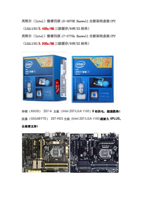
英特尔(Intel)酷睿四核i5-4670K Haswell全新架构盒装CPU (LGA1150/3.4GHz/6M三级缓存/84W/22纳米)英特尔(Intel)酷睿四核i7-4770k Haswell全新架构盒装CPU (LGA1150/3.5GHz/8M三级缓存/84W/22纳米)华硕(ASUS)Z87-A 主板(Intel Z87/LGA 1150)8相供电,超强散热!技嘉(GIGABYTE)Z87-HD3主板(Intel Z87/LGA 1150)超耐久4PLUS,全高清支持!航嘉(HuntKey)多核WD600 电源(额定功率600W/85%高效率/宽幅电压/超长背部走线)鑫谷(Segotep)额定500W GP600G黑金电源(80PLUS金牌/效率达87%以上,支持背线/超静音温控映众(Inno3D)GTX770 冰龙1098/7010MHz 2GB/256Bit GDDR5 PCI-E 显卡微星(MSI)N770 TF 2GD5/OC 1137(Boost Clock1198) /7010MHz 2048MB/256bit GDDR5 PCI-E显卡,10公分刀锋扇叶,五热管三星(SAMSUNG) 840Pro系列128G 2.5英寸SATA-3固态硬盘(MZ-7PD128BW)英特尔(Intel)530 系列固态硬盘120G 简包SATA3接口SSDSC2BW120A401九州风神(DEEPCOOL)玄冰400 多平台CPU散热器12025发光风扇四热管可调速超频三(PCCOOLER) 红海-至尊版全铜材质90mm智能温控风扇全平台CPU散热器恩杰(NZXT)PHANTOM 410 小幻影中塔游戏机箱红(原生USB3.0/背部走线/自带三个静音风扇/全兼容SSD)芝奇(G.SKILL)RipjawsX DDR3 2133 8G(4G×2条)台式机内存(F3-17000CL11D-8GBXL)海盗船(CORSAIR)复仇者DDR3 2133 8GB(2x4GB)台式机内存(CMZ8GX3M2A2133C11R)惠科(HKC) T7000+ 27英寸2560*1440顶级H-IPS屏LED背光宽屏液晶显示器点距0.233。

– 1 –– 2 – – 3 –P/N: 1802071100114UC-7112 Plus/7112/7110 Quick Installation GuideFifth Edition, January 20141. OverviewThe Moxa UC-7112 Plus, UC-7112, and UC-7110 are mini size RISC-based ready-to-run embedded computers that feature dual 10/100 Mbps Ethernet ports and two RS-232/422/485 serial ports in a built-in µClinux ARM9 box. In addition, the UC-7112 provides an internal SD socket for storage expansion, to offer highperformance communication and unlimited storage in a super compact, palm-size box. The UC-7112 Plus, UC-7112, andUC-7110 are the right solutions for embedded applications that use a lot of memory, but that must be housed in a small physical space without sacrificing performance.2. Package ChecklistBefore installing the UC-7112 Plus/7112/7110, verify that the package contains the following items: • 1 UC-7112 Plus, UC-7112,or UC-7110 • Quick Installation Guide • Document & Software CD• Cross-over Ethernet cable: RJ45 to RJ45, 100 cm • Console port cable: CBL-4PINDB9F-100(4-pin header to female DB9 cable, 100 cm) • Universal Power Adaptor•Product Warranty StatementOptional Accessories •DK-35ADIN-Rail Mounting Kit (35 mm)NOTE: Please notify your sales representative if any of the above items are missing or damaged.3. Hardware IntroductionLED IndicatorsThe following LED indicators are located on the top panel of the UC-7112 Plus/7112/7110.UC-7112 Plus/7112/7110 Top ViewThe top view of the UC-7112 is shown in the following figure. The UC-7112 Plus and UC-7110 look similar, except that the UC-7110 does not have an internal SD slot.UC-7112 Plus/7112/7110 DimensionsThe dimensions of the three products are shown in the following figure.4. Hardware Installation ProcedureSTEP 1: Remove the UC from the box and attach the poweradaptor.STEP 2: Connect the UC’s serial console cable to your PC’s RS-232COM port for initial setup through the console terminal.STEP 3: Connect the UC to a network. Use a standardstraight-through Ethernet cable to connect to a hub or switch. When setting up or testing the UC, you might find it convenient to connect directly to your computer’s Ethernet port. In this case, use a cross-over Ethernet cable.STEP 4: Install Secure Digital (SD) Memory Card (UC-7112and UC-7112 Plus only)To install an additional SD card, you must first remove the UC-7112’s outer cover to access the slot. The internal SD socket is located at the back side of the UC-7112 on the bottom board; you can find the SD socket on the right, a little lower than the cover screw. Plug the SD card directly into the socket. To remove the card, press it in first, and then remove your finger. The card will pop out enough to allow you to remove it.STEP 5: Placement OptionsIn addition to placing the UC on a desktop or other horizontal surface, you may also make use of the DIN-Rail or Wall Mount options, as illustrated here.Wall MountDIN-Rail5. Software Installation ProcedureSTEP 1: Insert the UC’s CD-ROM into your Windows or Linux PC,and then use Acrobat Reader to read the UC-7112/7110 Series User’s Manual.STEP 2: Install the UC’s tool chain, which is on the CD-ROM. Thetool chain consists of the following components:1. UC Finder: Broadcast search for the UC’s IP address on your LAN. The UC supports both Windows and Linux environments.2. Cross Compiler: Arm-elf-gcc for µClinux platforms (UC-7112/7110), and Arm-linux-gcc for embedded Linux platform (UC-7112 Plus). Both options are C/C++ PC cross compilers, which are gcc compilers that run on an x86 PC, but create an execution file for Arm-based platforms, such as the UC-7112/7110.– 4 – – 5 – – 6 –/supportThe Americas: +1-714-528-6777 (toll-free: 1-888-669-2872)Europe: +49-89-3 70 03 99-0 Asia-Pacific: +886-2-8919-1230China: +86-21-5258-9955 (toll-free: 800-820-5036)2014 Moxa Inc. All rights reserved.3. GNU C Library: The GNU standard POSIX C Library is supported for both the UC-7112 Plus’s Linux platform, and the UC-7112/7110’s uClinux platform. Glibc is for Linux and µClibc is for uClinux, which is an abbreviation for “microcontroller C library.” µClibc was created to support µClinux, a Linux port for MMU-lessmicrocontrollers, such as the ARM9 installed in the UC-7112/7110. For more information, visit .STEP 3: Edit source code on a Linux PC.STEP 4: Use the Cross Compiler to compile the source code, andthen use FTP to download the program to the UC.STEP 5: Run your program.6. System Commandsbusybox: Linux / µClinux normal command utility collection File manager cpcopy file ls list filelnmake symbolic link filemount mount and check file system rmdelete filechmod change file owner & group & user chown change file owner chgrp change file groupsync sync file system; save system file buffer to hardware mv move filepwd display active file directly df list active file system space du estimate file space usage mkdir make new directory rmdir delete directoryhead print the first 10 lines of each file to standard outputtail print the last 10 lines of each file to standard outputtouch update the access and modification times of each file to the current timeEditor vi text editorcat dump file contextgrep print lines matching a patterncut remove sections from each line of files find search for files in a directory hierarchy more dump file by one page test test if file exists or not echo echo stringProcess kill kill processkillall kill process by name ps report process statussleep suspend command on time (seconds)Networkping ping to test network route routing table manager netstat display network status ifconfig set network IP address tftp tftp protocoltelnet user interface to TELNET protocol ftpfile transfer protocoliptables-restore restore iptables configuration file to network iptablesiptables commandiptables-save save recent iptables configuration to file Otherdmesg dump kernel log message stty set serial portmknod make device nodefree display system memory usagedate print or set the system date and timeenv run a program in a modified environment clear clear the terminal screenreboot reboot / power off/on the server halthalt the servergzip, gunzip, zcatcompress or expand files hostname show system’s host name tartar archiving utilityMoxa special utilities cat /etc/version show user directory version upramdisk mount ramdisk downramdisk unmount ramdisk kversion show kernel versionfsversion show the root file system (firmware) version setinterface set UART interfaces program7. Pin AssignmentsDB9 MaleSerial Console Port*NC=Not Connected8. Environmental SpecificationsPower requirements 12 to 48 VDCOperating temp.-10 to 60°C (14 to 140°F), 5 to 95% RH Storage Temperature -20 to 80°C (-4 to 176°F), 5 to 95% RH Serial protection 15 KV ESD for serial port Magnetic isolation 1.5 KV for EthernetRegulatory approvals FCC Class A, CE Class A, UL, cUL, TÜV Warranty 5 years。

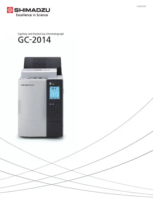
GC-2014Big Performance & Small Space GC-2014Improved design and innovative technology for all of our injectors, detectors and fl ow controllers equal or surpass our GC-2010 the high-end technology leader.High PerformanceSuperior PerformanceLarge LCD, all digital gases control and auto-diagnostics inherited from the GC-2010 – “The Most advanced, easy-to-use interface”Easy OperationExcellent User InterfaceUse any column types for any analysis. Packed or capillary columns give you the freedom to choose the best technique for your measurement. Fully integrated multiple valve systems are made simple for optimum performance for SystemGC custom GC products.FlexibilityExpandability for Every SituationSimple nozzle replacement supports both capillary and packed columns.Our New FPD is used for all columnsDetectorsHolophotal Flame Photometric DetectorPhotomultiplierFilter Lens Nozzle The detectors have been completely redesigned, incorporating the GC-2010 detector designs for capillary analyses and the GC-14 detector designs for packed columns. This TCD-2014 unit is ideal for packed column measurements employing the semi-diffusion cell designInjection unitswith unsurpassed accuracyThe design of the SPL-2014 capillary column sample injection unit is based on the GC-2010 technology.This accuracy was unattainable with previous models.The packed column sample injection unit employs the proven design of the GC-14 injection unit.Easier to understand, simpler operationLarge display, help functions and pop-up screens Loaded with productivity-enhancing functionsEasy OperationA large LCD displays chromatograms and method parameters.This is a great improvement for Chromatopacs systems that do not have these real time displays.Graphical user interface enables quick setting of all analytical conditions.The built-in Help function almost eliminates need for familiarization training.Large displayshows most analysis details at a glance,ideal for Chromatopac users.Graphical popup screen that clearly indicates thepolarity so manual injection errors are prevented when using the dual packed column system.Polarity display prevents injection errorsEasy-to-understand Pop-up ScreensChromatogram display Graphical U/IBuilt-in Help FunctionLarge Display6Self-diagnosticsUnit control check Hardware diagnosis Save and check diagnosis logGC-2014250mmGC-14230mmSolenoid valve unitManual fl ow controllersAFCSpeci fi cationsDetectorsTemperature range Temperature settingNo. of units installed simultaneously Detector type 400°C max. (FID, TCD, FTD) 350°C max. (ECD, FPD) 1°C stepsUp to 4 units (restricted depending on detector type) FID, TCD, ECD, FPD, FTD for capillary/packedDual fl ow rate differential system400°C max.3pgC/s (dodecane)107Quartz glass Standard: for packed, Option: for capillaryFlame Ionization Detector (FID) SystemTemperature rangeMinimum detected quantityDynamic rangeNozzleThermal Conductivity Detector (TCD)System Temperature range Dynamic range Sensitivity Dual fl ow rate differential system400°C max.10540,000mV · mL/mg (built-in pre-ampli fi er, with 10 × ampli fi cation)Electron Capture Detector (ECD)SystemTemperature range Minimum detected quantity Dynamic range Fixed current system using 63Ni370MBq radiation source 400°C max.0.1pg/s (γ-BHC)104Flame Photometric Detector (FPD)Temperature range Dynamic rangeMinimum detected quantity 350°C max.P: 104S: 103P: 0.5pgP/s (tributyl phosphate) S: 8pgS/s (dodecane thiol)Flame Thermionic Detector (FTD)Temperature range Dynamic rangeMinimum detected quantity (Two types, one for capillary and one for packed. The speci fi cation are the same.) 400°C max.N: 103P: 103N: 0.4pgN/s (azobenzene)P: 0.05pgP/s (malathion)Display240 × 320 dot graphics display (30 characters × 16 lines)Dimensions, Weight, Power Requirements (GC main unit)Dimensions WeightPower Requirements 400 (W) × 690 (H) × 607 (D) mm48kg (GC-2014AF model)AC100V/120V 230V1800VA (GC-2014AF model) or2600VA (GC-2014AF model), 50/60HzColumn OvenTemperature range DimensionsOven capacity Temperature accuracy Temperature deviation Temperature variation coef fi cient Temperature program steps Programmed rate setting range Total time for all steps Linear heating rangeCooling rateColumns accepted (Ambient + 10°C) ~ 400°C (using liquid CO2 gas*: -50°C ~400°C)250 (W) × 360 (H) × 175 (D) mm15.8LSet value (K) ± 1% (calibration at 0.01°C increments)2°C max. (on 200mm dia. circumference 30mm from rear)0.01°C/°CUp to 20 (cooling program possible)-250°C ~ 250°C/min9999.99 minutes max.30°C/min up to 150°C20°C/min up to 250°C10°C/min up to 380°C7°C/min up to 400°C (at 25°C ambient temperature)300°C ~ 50°C in 6 min max. (at 25°C ambient temperature)Capillary columns: 2Packed columns for GC14B: 4 (Glass columns: 2)Sample Injection UnitTemperature rangeHeating settingsNo. of units installed simultaneously Sample injection unit types Up to 400°C1°C stepsUp to 3 unitsDual packed, single packed, split/splitless, direct, direct (AMC)Carrier Gas Flow Controller For Packed / DualFlow rate setting range Programmable steps Programmed rate setting range Correction function 0 ~ 100mL/min7-400 ~ 400mL/minMaintains column fl ow rate during column oven heatingFor Capillary Split/Splitless, Direct (Split/splitless injection mode)Pressure setting range Programmable steps Programmed rate setting range Split ratio setting rangeTotal fl ow rate setting range Correction function 0 ~ 970kPa7 (pressure-decreasing program possible)-400 ~ 400kPa/min0 ~ 9999.90 ~ 1200mL/minMaintains column average linear velocity during column oven heating (for capillary only)(Pressure mode direct injection)Pressure setting range Programmable steps Programmed rate setting range Correction function 0 ~ 970kPa/min7-400 ~ 400kPa/minMaintains column average linear velocity during column oven heating (for capillary only)(Flow-rate mode direct injection)Flow rate setting range Programmable steps Programmed rate setting range 0 ~ 1200mL/min 7-400 ~ 400mL/minFor Single Packed, Direct (AMC)Flow rate setting range Correction function 0~100mL/minMaintenance column fl ow rate during column oven heating*Optional parts are required to use liquid CO2 gas.。

元件認證指南目錄飲用水處理系統和元件認證指南章節-----------------------------------------------------------------------------------頁碼序--------------------------------------------------------------------------------------1-4 概況-----------------------------------------------------------------------------------5常見問題-----------------------------------------------------------------------------6-8 NSF標準規定-----------------------------------------------------------------------9-15 認證-----------------------------------------------------------------------------------15-18 與供應商合作-----------------------------------------------------------------------19詞彙表--------------------------------------------------------------------------------20-24 附錄A--------------------------------------------------------------------------------25附錄B--------------------------------------------------------------------------------26附錄C--------------------------------------------------------------------------------27-28 聯絡資訊-----------------------------------------------------------------------------29序NSF International(簡稱NSF)成立於1944年,為一個致力於公共衛生安全以及環境保護的機構。

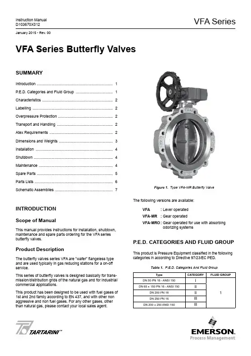
VFA SeriesInstruction Manual D103670X012January 2015 - Rev. 00TMVFA Series Butterfly ValvesSummaryIntroduction ........................................................................ 1P .E.D. Categories and Fluid Group ................................... 1Characteristics ................................................................... 2Labelling ............................................................................ 2Overpressure Protection .................................................... 2Transport and Handling ..................................................... 2Atex Requirements ............................................................ 2Dimensions and Weights ................................................... 3Installation ......................................................................... 4Shutdown ........................................................................... 4Maintenance ...................................................................... 4Spare Parts ........................................................................ 5Parts Lists .......................................................................... 6Schematic Assemblies . (7)INTrODuCTION Scope of ManualThis manual provides instructions for installation, shutdown, maintenance and spare parts ordering for the VFA series butterfly valves.Product DescriptionThe butterfly valves series VFA are "wafer" flangeless type and are used typically in gas reducing stations for a on-off service.This series of butterfly valves is designed basically for trans-mission/distribution grids of the natural gas and for industrial/commercial applications.This product has been designed to be used with fuel gases of 1st and 2nd family according to EN 437, and with other non aggressive and non fuel gases. For any other gases, other than natural gas, please contact your local sales agent.Figure 1. Type VFA-MR Butterfly ValveThe following versions are available:VFa : Lever operated VFa-mr : Gear operatedVFa-mrO : Gear operated for use with absorbingodorizing systemsP .E.D. CaTEGOrIES aND FLuID GrOuPThis product is Pressure Equipment classified in the following categories in according to Directive 97/23/EC PED.Table 1. P.E.D. Categories And Fluid GroupTypeCaTEGOryFLuID GrOuPDN 50 PN 16 - ANSI 150I 1DN 65 ÷ 150 PN 16 - ANSI 150II DN 200 PN 16II DN 250 PN 16III DN 200 ÷ 250 ANSI 150IIIVFA Series2CharaCTErISTICSBody Sizes and End Connection StylesVFa • VFa-mr • VFa-mrODN 50 - 65 - 80 - 100 - 125 - 150 - 200 - 250PN 16 - ANSI 150 flangedThe pressure/temperature limits indicated in this instruction manual or any applicable standard or code limitation should not be exceeded.Maximum Operating Inlet PressurePN 16: 16 bar ANSI 150: 19 barAt average ambient temperature.Minimum/Maximum Allowable Temperature (TS)See labelTemperatureStandard Version:Working -10° to 60°CLow Temperature Version: Working -20° to 60°CMaterialsBody: Steel Disk: Pressed steel Shaft:Stainless steelGaskets: Nitrile NBR rubber (FKM on request)LabELLINGFigure 2. Label for VFA SeriesNote 1: See “Characteristics” Note 2: Year of manufacture Note 3: Temperature class -10°/60°C or -20°/60°C Note 4: PN 16 PS: 16 bar ANSI 150 PS: 19.3 barThe Category I pressure equipments will not have on label any Notified Body reference.OVErPrESSurE PrOTECTIONThe recommended safety pressure limitations are stamped on the valve nameplate (PS). Some type of overpressure protec-tion is needed if the actual inlet pressure exceeds this limits.Personal injury, equipment damage, or leakage due to es-caping fluid or bursting of pressure-containing parts may re-sult if this relief valve is over-pressured or is installed where service conditions could exceed the design operative limits.Valves operation below the maximum pressure limitations does not preclude the possibility of damage from external sources or debris in the line.The valves should be inspected for damage after any over-pressure condition..TraNSPOrT aND haNDLINGEstablished transport and handling procedures shall be fol -lowed to avoid any damage on the pressure containing parts (valve body) by shocks or anomalous stresses.In case of necessity of a harness, a nylon harness will have to be used in order to protect the surface and possible valve accessories.aTEX rEquIrEmENTSIf the provisions of EN 12186 & EN 12279, national regulations, if any, and specific manufacturer recommendations are not put into practice before installation and if purge by inert gas is not carried out before equip -ment’s start-up and shut-down operations, a potential external and internal explosive atmosphere can be present in equipment & gas pressure regulating/measuring stations/installations.VFA Series3If a presence of foreign material in the pipelines is foreseen and purge by inert gas is not carried out, the following procedure is recommended to avoid any possible external ignition source inside the equipment due to mechanical generated sparks :• drainage to safe area via drain lines of foreign materials, if any, by inflow of fuel gas with low velocity in the pipe-work ( 5m/sec)In any case,• provisions of Directive 1999/92/EC and 89/655/EC shall be enforced by gas pressure regulating/measuring station/installation’s end user • with a view to preventing and providing protection against explosions, technical and/or organizational measuresappropriate to the nature of the operation shall be taken (e.g. : filling/exhausting of fuel gas of internal volume of the isolated part/entire installation with vent lines to safe area - 7.5.2 of EN 12186 & 7.4 of EN 12279 ; monitoring of settings with further exhaust of fuel gas to safe area ; connection of isolated part/entire installation to downstream pipeline; ….)• provision in 9.3 of EN 12186 & 12279 shall be enforced by pressure regulating/measuring station/installation’s end user • external tightness test shall be carried out after each reassembly at installation site using testing pressure in accordance with national rules • periodical check/maintenance for surveillance shall be carried out complying with national regulations, if any, andspecific manufacturer recommendations.VFA SERIESVFA-MR AND VFA-MRO SERIESTable 2. VFA Series Dimensions (mm) and Weights (kg)Figure 3. VFA Series DimensionsDImENSIONS aND WEIGhTSVFA Series4INSTaLLaTIONOnly qualified personnel should install or service a butterfly valve.Butterfly valves should be installed, oper -ated, and maintained in accordance with international and applicable codes and regu -lations, and Emerson instructions.Clean out all pipelines before installation of the regulator and check to be sure the regu -lator has not been damaged or has collected foreign material during shipping.Possible fails that cause the shutdown of the valve can create hazard conditions.Personal injury, equipment damage, orleakage due to escaping fluid or bursting of pressure-containing parts may result if this valve is over pressured or is installed where service conditions could exceed the limits given in the Specifications section, or where conditions exceed any ratings of the adja -cent piping or piping connections.Additionally, physical damage to the valve could result in personal injury and property damage due to escaping fluid. To avoid such injury and damage, install the regulator in a safe location..To avoid this, install the butterfly valve:• In a safe area where the is protected from exposure to physical damage and/or corrosive substances • service conditions are within valve capabilities Don’t exceed any ratings of the adjacent flanges or piping connections.Install the valve in any position desired, unless otherwise specified, but be sure flow through the body is in the direction indicated by the arrow on the body.If using a VFA series butterfly valve on hazardous or flam-mable gas service, personal injury and property damage could occur due to fire or explosion of vented gas that may have accumulated.To prevent such injury or damage, provide piping or tubing to vent the gas to a safe, well-ventilated area in accordance also with international and applicable codes and regulations. In particular, when venting a hazardous gas, the piping or tubing should be located far enough away from any buildings or win-dows so to not create a further hazard, and the vent opening should be protected against anything that could clog it.For outdoor installations, the butterfly valve should be located away from vehicular traffic.In order to avoid damaging of the valve disc, special care has to be done in carrying out accurate measurements to assess that it can rotate in the flange of connection and in the pipe without difficulties.Furthermore, center correctly the valve on the connection flanges.A suggested bolt tightening sequence is to process “three o’clock, nine o’clock, twelve o’clock, six o’clock, etc.”. Not ap-ply never the pressure to only partially installed valve.Further the ENs 12186 & 12279, where this product is used : • provide the cathodic protection and electrical isolation to avoid any corrosionShuTDOWNTo avoid personal injury resulting from sud -den release of pressure, isolate the valve from all pressure before attempting disas -sembly and release trapped pressure from the equipment and pressure line.In case of disassembly of main pressure retaining parts for checks and maintenance procedures, external and internal tightness tests have to be done according to appli -cable codes.maINTENaNCE(See Figure 4 and 5)All maintenance procedures must be carried out only by qualified personnel.If necessary, contact our technical support representatives or our authorized dealers.Butterfly valve and its pressure accessories are subject to normal wear and must be inspected periodically and replaced as necessary.VFA Series5The frequency of inspection/checks and replacementdepends upon the severity of service conditions and upon applicable codes and national standards/rules .In accordance with applicable National or Industry codes, standards and regulations/recommendations, all hazards covered by specific tests after final assembling beforeapplying the CE marking, shall be covered also after every subsequent reassembly at installation site, in order to ensure that the equipment will be safe throughout its intended life.Before proceeding with any maintenance work, shutoff the gas upstream and downstream from the regulator, also ensure that there is no gas under pressure inside the body by loosening the upstream and downstream connections.Upon completion, check for leaks using suds.General Maintenancea. Turn valve to “close” position and remove “open” control. Servicing mode will depend on the type of valve control.b. Remove screws (key 23 for sizes DN 50 to DN 200 and key 27 for DN 250), slide off valve body from pipe and replace O-ring (key 7). Note: It may sometimes be neces-sary to widen counterflanges so as to remove valve.c. Remove screws (key 12), hub (key 1) and upper bushing (key 9), and replace O-ring (key 13 and 14).d. On sizes DN 50 to DN 200: Remove dowels (key 6).On size DN 250: Remove bush (key 22), pin (key 6) and replace O-ring (key 20 and 21) if worn.e. Remove shaft (key 4).f. Remove disk (key 8).g. Remove screws (key 11) and plate (key 5).h. Replace gasket unit (key 3) and O-ring (key 6) if worn.i. On sizes DN 125 to DN 200: remove screws (key 17), plug (key 19) and replace O-ring (key 18 and 24).On size DN 250: remove screws (key 19), plug (key 17) and replace O-ring (key 18, 23 and 7).ReassemblyLubricates all seals with “MOLYKOTE 55 M” molybdenum grease.Use the greatest care to avoid damage to seals.Reassemble by reversing the above steps.Tighten all screws uniformly to ensure proper sealing.SParE ParTSSpare parts storage shall be done by proper procedures according to national standard/rules to avoid over aging or any damage.VFA Series6ParTS LISTSVFa Series DN 50 to DN 200 (See Figure 4)Key Description 1 Hub 2 Body 3* Gasket unit 4 Shaft 5 Plate 6 Dowel 7* O-ring 8 Disk9 Upper bushing 10 Lower bushing 11 Screw 12 Screw 13* O-ring 14* O-ring 15 Label 16 Rivet 17 Screw 18* O-ring 19 Plug 20* Gasket 21 Flange 22 Washer 23ScrewVFa Series DN 250 (See Figure 5)Key Description 1 Hub 2 Body 3* Gasket unit 4 Shaft 5 Plate 6 Pin 7* O-ring 8 Disk9 Upper bushing 10 Lower bushing 11 Screw 12 Screw 13* O-ring 14* O-ring 15 Label 16 Rivet 17 Plug 18* O-ring 19 Screw 20* O-ring 21* O-ring 22 Bush 24* Gasket 25 Flange 26 Washer 27ScrewRubber parts marked with (*) are supplied in the “spare parts kit”, recommended as stock.To order the kit it is necessary to communicate to us the type of the valve and its serial number.VFA Series SChEmaTIC aSSEmbLIESLM/7124Figure 4. VFA Butterfly Valve DN 50 to DN 2007VFA SeriesThe Emerson logo is a trademark and service mark of Emerson Electric Co. All other marks are the property of their prospective owners. Tartarini is a mark of O.M.T. Officina Meccanica Tartarini s.r.l., a business of Emerson Process Management.The contents of this publication are presented for informational purposes only, and while every effort has been made to ensure their accuracy, they are not to be construed as warranties or guarantees, express or implied, regarding the products or services described herein or their use or applicability. We reserve the right to modify or improve the designs or specifications of such products at any time without notice.Emerson Process Management Regulator Technologies, Inc., does not assume responsibility for the selection, use or maintenance of any product. Responsibility for proper selection, use and maintenance of any Emerson Process Management Regulator Technologies, Inc., product remains solely with the purchaser.©Emerson Process Management Regulator Technologies, Inc., 2015; All Rights ReservedIndustrial RegulatorsEmerson Process Management Regulator Technologies, A - HeadquartersMcKinney, Texas 75070, USA Tel: +1 800 558 5853Outside U.S. +1 972 548 3574Asia-PacificShanghai 201206, China Tel: +86 21 2892 9000EuropeBologna 40013, Italy Tel: +39 051 419 0611Middle East and AfricaDubai, United Arab Emirates Tel: +971 4811 8100For further information visit /regulatorsNatural Gas Technologies Emerson Process Management Regulator Technologies, A - HeadquartersMcKinney, Texas 75070, USA Tel: +1 800 558 5853Outside U.S. +1 972 548 3574Asia-PacificSingapore 128461, Singapore Tel: +65 6777 8337EuropeO.M.T. Tartarini s.r.l. Via P . Fabbri 1, I-40013 Castel Maggiore (Bologna), Italy Tel: +39 051 419 0611Francel SAS, 3 ave Victor Hugo, CS 80125 - Chartres 28008, France Tel: +33 2 37 33 47 00Middle East and AfricaDubai, United Arab Emirates Tel: +971 4811 8100TESCOMEmerson Process ManagementTescom CorporationUSA - HeadquartersElk River, Minnesota 55330-2445, USA Tels: +1 763 241 3238 +1 800 447 1250Asia-PacificShangai 201206, China Tel: +86 21 2892 9499EuropeSelmsdorf 23923, Germany Tel: +49 38823 31 287O.M.T. Officina Meccanica Tartarini S.R.L., R.E.A 184221 BO Cod. Fisc. 00623720372 Part. IVA 00519501209 N° IVA CEE IT 00519501209, Cap. Soc. 1.548 000 Euro i.v. R.I. 00623720372 - M BO 020330Francel SAS , SIRET 552 068 637 00057 APE 2651B, N° TVA : FR84552068637, RCS Chartres B 552 068 637, SAS capital 534 400 Euro Figure 5. VFA Butterfly Valve DN 250LM/7125。

Eaton 210070Eaton Moeller® series Z5 Overload relay, Ir= 50 - 70 A, 1 N/O, 1 N/C, For use with: DILM250General specificationsEaton Moeller® series Z5 Thermal overload relay210070Z5-70/FF2504015082100704146 mm 167 mm 128 mm 1.725 kgCSA File No.: 012528 UL CE CSACSA Class No.: 3211-03 IEC/EN 60947CSA-C22.2 No. 60947-4-1-14 UL File No.: E29184UL Category Control No.: NKCR IEC/EN 60947-4-1 UL 60947-4-1 VDE 0660Product NameCatalog Number Model Code EANProduct Length/Depth Product Height Product Width Product Weight Certifications70 A1 x (0.75 - 2.5) mm², Control circuit cables2 x (0.75 - 2.5) mm², Control circuit cablesIs the panel builder's responsibility. The specifications for the switchgear must be observed.8 mm25 °CMeets the product standard's requirements.Is the panel builder's responsibility. The specifications for the switchgear must be observed.Direct attachmentSeparate mountingDirect mountingDoes not apply, since the entire switchgear needs to be evaluated.40 °CMeets the product standard's requirements.AutomaticPush-button250 A, max. Fuse, SCCR (UL/CSA)250 A, max. CB, SCCR (UL/CSA)10 kA, SCCR (UL/CSA)Is the panel builder's responsibility.Product Range Catalog Switching and protecting motorseaton-tripping-z5-overload-relay-characteristic-curve.epseaton-tripping-devices-z5-overload-relay-characteristic-curve.epsDA-DC-00004856.pdfDA-DC-00004846.pdfeaton-tripping-devices-overload-relay-z5-overload-relay-dimensions-002.epseaton-tripping-devices-overload-relay-z5-overload-relay-3d-drawing.eps ETN.Z5-70_FF250IL03407138ZIL03407081ZIL03407006ZDA-MN-h1476dgbDA-CD-z5_ff250DA-CS-z5_ff250eaton-tripping-devices-overload-relay-zeb-overload-relay-wiring-diagram.epseaton-general-release-zeb-overload-relay-wiring-diagram.epsRated operational current for specified heat dissipation (In) Terminal capacity (flexible with ferrule)10.11 Short-circuit ratingStripping length (control circuit cable)Ambient operating temperature (enclosed) - min10.4 Clearances and creepage distances10.12 Electromagnetic compatibilityMounting method10.2.5 LiftingAmbient operating temperature (enclosed) - max10.2.3.1 Verification of thermal stability of enclosures Reset functionShort-circuit current rating (basic rating)10.8 Connections for external conductors Catalogues Characteristic curve Declarations of conformity DrawingseCAD modelInstallation instructionsManuals and user guides mCAD modelWiring diagramsM3.5, Terminal screw, Control circuit cablesM10 x 35, Terminal screw, Main connectionsAdjustable current range - min50 ATerminal capacity (flexible with cable lug)185 mm²ProtectionWith terminal cover, Protection against direct contact when actuated from front (EN 50274)Ambient operating temperature - max60 °CClimatic proofingDamp heat, cyclic, to IEC 60068-2-30Damp heat, constant, to IEC 60068-2-78FeaturesPhase-failure sensitivity (according to IEC/EN 60947, VDE 0660 Part 102)Test/off buttonTrip-free releaseReset pushbutton manual/autoStatic heat dissipation, non-current-dependent Pvs0 WElectrical connection type of main circuitScrew connection10.9.3 Impulse withstand voltageIs the panel builder's responsibility.Voltage rating - max600 VACTerminal capacity (busbar)25 mm width, Main connectionAmbient operating temperature - min-25 °C10.6 Incorporation of switching devices and componentsDoes not apply, since the entire switchgear needs to be evaluated.10.5 Protection against electric shockDoes not apply, since the entire switchgear needs to be evaluated.240 V AC, Between auxiliary contacts, According to EN 61140 440 V, Between auxiliary contacts and main contacts, According to EN 61140500 V AC, Between main circuits, According to EN 61140Rated operational current (Ie) at AC-15, 220 V, 230 V, 240 V1.5 AClassCLASS 10 A10.13 Mechanical functionThe device meets the requirements, provided the information in the instruction leaflet (IL) is observed.10.2.6 Mechanical impactDoes not apply, since the entire switchgear needs to be evaluated.10.9.4 Testing of enclosures made of insulating materialIs the panel builder's responsibility.Number of contacts (normally closed contacts)110.3 Degree of protection of assembliesDoes not apply, since the entire switchgear needs to be evaluated.Rated operational current (Ie) at AC-15, 380 V, 400 V, 415 V0.9 AHeat dissipation per pole, current-dependent Pvid7 WProduct categoryOverload relay Z5Overload release current setting - min50 ARated operational current (Ie) at DC-13, 60 V0.75 AEquipment heat dissipation, current-dependent Pvid21 WHeat dissipation capacity Pdiss0 WSuitable forBranch circuits, (UL/CSA)Terminal capacity (stranded with cable lug)185 mm²Temperature compensation≤ 0.25 %/K, residual error for T > 40° ContinuousTerminal capacity (solid)2 x (0.75 - 4) mm², Control circuit cables1 x (0.75 - 4) mm², Control circuit cablesNumber of auxiliary contacts (normally closed contacts)110.2.3.2 Verification of resistance of insulating materials to normal heatMeets the product standard's requirements.10.2.3.3 Resist. of insul. mat. to abnormal heat/fire by internal elect. effectsMeets the product standard's requirements.Width across flats16 mm (Hexagon head spanner SW)Rated operational current (Ie) at DC-13, 220 V, 230 V0.2 AConventional thermal current ith of auxiliary contacts (1-pole, open)6 AOverload release current setting - max70 ATerminal capacity (solid/stranded AWG)2 x (18 - 14), Control circuit cables2/0 - 500 MCM, Main cables10.9.2 Power-frequency electric strengthIs the panel builder's responsibility.Degree of protectionIP00Overvoltage categoryIIINumber of auxiliary contacts (change-over contacts)Pollution degree310.7 Internal electrical circuits and connectionsIs the panel builder's responsibility.Rated impulse withstand voltage (Uimp)8000 V AC4000 V (auxiliary and control circuits)10.10 Temperature riseThe panel builder is responsible for the temperature rise calculation. Eaton will provide heat dissipation data for the devices.Tightening torque18 Nm, Main cable connection screw/bolt1.2 Nm, Screw terminals, Control circuit cablesAdjustable current range - max70 AScrewdriver size1 x 6 mm, Terminal screw, Control circuit cables, Standard screwdriver2, Terminal screw, Control circuit cables, Pozidriv screwdriverRated operational current (Ie) at AC-15, 120 V1.5 A10.2.2 Corrosion resistanceMeets the product standard's requirements.10.2.4 Resistance to ultra-violet (UV) radiationMeets the product standard's requirements.10.2.7 InscriptionsMeets the product standard's requirements.Number of contacts (normally open contacts)1Short-circuit protection ratingMax. 6 A gG/gL, fuse, Without welding, Auxiliary and control circuits160 A gG/gL, Fuse, Type “2” coordination250 A gG/gL, Fuse, Type “1” coordinationNumber of auxiliary contacts (normally open contacts)1Rated operational current (Ie) at DC-13, 110 V0.4 ARated operational voltage (Ue) - max1000 VShock resistanceEaton Corporation plc Eaton House30 Pembroke Road Dublin 4, Ireland © 2023 Eaton. All rights reserved. Eaton is a registered trademark.All other trademarks areproperty of their respectiveowners./socialmedia10 g, Mechanical, Sinusoidal, Shock duration 10 ms 0.9 AB300 at opposite polarity, AC operated (UL/CSA) R300, DC operated (UL/CSA)B600 at opposite polarity, AC operated (UL/CSA)Rated operational current (Ie) at DC-13, 24 V Switching capacity (auxiliary contacts, pilot duty)。
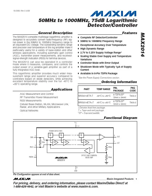
General DescriptionThe MAX2014 complete multistage logarithmic amplifier is designed to accurately convert radio-frequency (RF) sig-nal power in the 50MHz to 1000MHz frequency range to an equivalent DC voltage. The outstanding dynamic range and precision over temperature of this log amplifier make it particularly useful for a variety of base-station and other wireless applications, including automatic gain control (AGC), transmitter power measurements, and received-signal-strength indication (RSSI) for terminal devices.The MAX2014 can also be operated in a controller mode where it measures, compares, and controls the output power of a variable-gain amplifier as part of a fully integrated AGC loop.This logarithmic amplifier provides much wider mea-surement range and superior accuracy compared to controllers based on diode detectors, while achieving excellent temperature stability over the full -40°C to +85°C operating range.ApplicationsAGC Measurement and Control RF Transmitter Power Measurement RSSI MeasurementsCellular Base-Station, WLAN, Microwave Link,Radar, and other Military Applications Optical NetworksFeatures♦Complete RF Detector/Controller ♦50MHz to 1000MHz Frequency Range ♦Exceptional Accuracy Over Temperature ♦High Dynamic Range♦2.7V to 5.25V Supply Voltage Range*♦Scaling Stable Over Supply and Temperature Variations♦Controller Mode with Error Output♦Shutdown Mode with Typically 1µA of Supply Current♦Available in 8-Pin TDFN PackageMAX201450MHz to 1000MHz, 75dB LogarithmicDetector/Controller________________________________________________________________Maxim Integrated Products1Ordering InformationFunctional Diagram19-0583; Rev 0; 6/06For pricing, delivery, and ordering information,please contact Maxim/Dallas Direct!at 1-888-629-4642, or visit Maxim’s website at .Pin Configuration appears at end of data sheet.*See the Power-Supply Connections section.+Denotes lead-free package.T = Tape-and-reel package.*EP = Exposed paddle.M A X 201450MHz to 1000MHz, 75dB Logarithmic Detector/ControllerABSOLUTE MAXIMUM RATINGSDC ELECTRICAL CHARACTERISTICS(MAX2014 Typical Application Circuit (Figure 1), V S = +3.3V, f RF = 50MHz to 1000MHz, R1 = 0Ω, R4 = 0Ω, R L = 10k Ω, T A = -40°C to +85°C, unless otherwise noted. Typical values are at T A = +25°C, unless otherwise noted.) (Note 1)Stresses beyond those listed under “Absolute Maximum Ratings” may cause permanent damage to the device. These are stress ratings only, and functional operation of the device at these or any other conditions beyond those indicated in the operational sections of the specifications is not implied. Exposure to absolute maximum rating conditions for extended periods may affect device reliability.V CC (Pins 1, 4) to GND........................................-0.3V to +5.25V SET, PWDN to GND....................................-0.3V to (V CC + 0.3V)Input Power Differential INHI, INLO................................+23dBm Input Power Single Ended (INHI or INLO grounded).....+19dBm Continuous Power Dissipation (T A = +70°C)8-Pin TDFN (derate 18.5mW/°C above +70°C).........1480mWθJA (without airflow)..........................................................54°C/W θJC (junction to exposed paddle)...................................8.3°C/W Operating Temperature Range ...........................-40°C to +85°C Junction Temperature......................................................+150°C Storage Temperature Range.............................-65°C to +150°C Lead Temperature (soldering, 10s).................................+300°CMAX201450MHz to 1000MHz, 75dB LogarithmicDetector/Controller_______________________________________________________________________________________3AC ELECTRICAL CHARACTERISTICS (continued)Note 2:Typical minimum and maximum range of the detector at the stated frequency.Note 3:Dynamic range refers to the range over which the error remains within the stated bounds. The error is calculated at T A = -40°Cand +85°C, relative to the curve at T A = +25°C.Note 4:The slope is the variation of the output voltage per change in input power. It is calculated by fitting a root-mean-square(RMS) straight line to the data indicated by RF input power range.Note 5:The intercept is an extrapolated value that corresponds to the output power for which the output voltage is zero.It is calculated by fitting an RMS straight line to the data.M A X 201450MHz to 1000MHz, 75dB Logarithmic Detector/Controller 4_______________________________________________________________________________________OUTPUT VOLTAGE vs. INPUT POWERINPUT POWER (dBm)O U T P U T V O L T A G E (V )-10-20-70-60-50-40-300.60.81.01.21.41.61.82.00.4-80OUTPUT VOLTAGE ERROR vs. INPUT POWERINPUT POWER (dBm)E R R O R (d B )-80-70-60-50-40-30-20-100-3-2-10123OUTPUT VOLTAGE ERROR vs. INPUT POWERINPUT POWER (dBm)E R R O R (d B )-80-70-60-50-40-30-20-10-3-2-10123OUTPUT VOLTAGE ERROR vs. INPUT POWERINPUT POWER (dBm)E R R O R (d B )-80-70-60-50-40-30-20-100-3-2-10123OUTPUT VOLTAGE vs. INPUT POWERINPUT POWER (dBm)O U T P U T V O L T A G E (V )-80-70-60-50-40-30-20-1000.40.60.81.01.21.41.61.82.0OUTPUT VOLTAGE ERROR vs. INPUT POWERINPUT POWER (dBm)E R R O R (d B )-80-70-60-50-40-30-20-100-3-2-10123OUTPUT VOLTAGE ERROR vs. INPUT POWERINPUT POWER (dBm)E R R O R (d B )-80-70-60-50-40-30-20-100-3-2-10123OUTPUT VOLTAGE ERROR vs. INPUT POWERINPUT POWER (dBm)E R R O R (d B )-80-70-60-50-40-30-20-100-3-2-10123Typical Operating Characteristics(MAX2014 Typical Application Circuit (Figure 1), V S = V CC = 3.3V, P IN = -10dBm, f IN = 100MHz, R1 = 0Ω, R4 = 0Ω, R L = 10k Ω,V PWDN = 0V, T A = +25°C, unless otherwise noted.)MAX201450MHz to 1000MHz, 75dB LogarithmicDetector/Controller_______________________________________________________________________________________5Typical Operating Characteristics (continued)(MAX2014 Typical Application Circuit (Figure 1), V S = V CC = 3.3V, P IN = -10dBm, f IN = 100MHz, R1 = 0Ω, R4 = 0Ω, R L = 10k Ω,V PWDN = 0V, T A = +25°C, unless otherwise noted.)OUTPUT VOLTAGE ERROR vs. INPUT POWERINPUT POWER (dBm)E R R O R (d B )-80-70-60-50-40-30-20-100-3-2-10123OUTPUT VOLTAGE ERROR vs. INPUT POWERINPUT POWER (dBm)E R R O R (d B )-80-70-60-50-40-30-20-100-3-2-10123OUTPUT VOLTAGE ERROR vs. INPUT POWERINPUT POWER (dBm)E R R O R (d B )-80-70-60-50-40-30-20-10-3-2-10123OUTPUT VOLTAGE vs. INPUT POWERINPUT POWER (dBm)O U T P U T V O L T A G E (V )-80-70-60-50-40-30-20-1000.40.60.81.01.21.41.61.82.0OUTPUT VOLTAGE ERROR vs. INPUT POWERINPUT POWER (dBm)E R R O R (d B )-80-70-60-50-40-30-20-100-3-2-10123OUTPUT VOLTAGE ERROR vs. INPUT POWERINPUT POWER (dBm)E R R O R (d B )-80-70-60-50-40-30-20-100-3-2-1123OUTPUT VOLTAGE vs. INPUT POWERINPUT POWER (dBm)O U T P U T V O L T A G E(V )-80-70-60-50-40-30-20-100.40.60.81.01.21.41.61.82.0M A X 201450MHz to 1000MHz, 75dB Logarithmic Detector/Controller 6_______________________________________________________________________________________Typical Operating Characteristics (continued)(MAX2014 Typical Application Circuit (Figure 1), V S = V CC = 3.3V, P IN = -10dBm, f IN = 100MHz, R1 = 0Ω, R4 = 0Ω, R L = 10k Ω,V PWDN = 0V, T A = +25°C, unless otherwise noted.)OUTPUT VOLTAGE ERROR vs. INPUT POWERINPUT POWER (dBm)E R R O R (d B )-80-70-60-50-40-30-20-10-3-2-10123OUTPUT VOLTAGE ERROR vs. INPUT POWERINPUT POWER (dBm)E R R O R (d B )-80-70-60-50-40-30-20-10-3-2-10123OUTPUT VOLTAGE vs. INPUT POWERINPUT POWER (dBm)O U T P U T V O L T A G E(V )-80-70-60-50-40-30-20-100.40.60.81.01.21.41.61.82.0OUTPUT VOLTAGE ERROR vs. INPUT POWERINPUT POWER (dBm)E R R O R (d B )-80-70-60-50-40-30-20-10-3-2-10123OUTPUT VOLTAGE vs. FREQUENCYFREQUENCY INPUT (MHz)O U T P U T V O L T A G E (V )20040060080010000.40.60.81.01.21.41.61.82.0OUTPUT VOLTAGE ERROR vs. INPUT POWERINPUT POWER (dBm)E R R O R (d B )-80-70-60-50-40-30-20-10-3-2-10123OUTPUT VOLTAGE vs. FREQUENCYFREQUENCY INPUT (MHz)O U T P U TV O L T A G E (V )20040060080010000.40.60.81.01.21.41.61.82.0MAX201450MHz to 1000MHz, 75dB LogarithmicDetector/ControllerOUTPUT VOLTAGE vs. FREQUENCYFREQUENCY INPUT (MHz)O U T P U T V O L TA G E (V )20040060080010000.40.60.81.01.21.41.61.82.0RF PULSE RESPONSETIME (50ns/div)R F I N P U T V O L T A G E , O U T P U T V O L T A G E(V )-1.0-0.500.51.01.52.02.5S11 MAGNITUDEFREQUENCY (MHz)M A G N I T U D E (d B )02004006008001000-25.0-22.5-20.0-17.5-15.0-12.5-10.0S11 MAGNITUDEFREQUENCY (MHz)M A G N I T U D E (d B )02004006008001000-25.0-22.5-20.0-17.5-15.0-12.5-10.0Typical Operating Characteristics (continued)(MAX2014 Typical Application Circuit (Figure 1), V S = V CC = 3.3V, P IN = -10dBm, f IN = 100MHz, R1 = 0Ω, R4 = 0Ω, R L = 10k Ω,V PWDN = 0V, T A = +25°C, unless otherwise noted.)M A X 201450MHz to 1000MHz, 75dB Logarithmic Detector/Controller 8_______________________________________________________________________________________Detailed DescriptionThe MAX2014 is a successive detection logarithmic amplifier designed for use in RF power measurement and AGC applications with a 50MHz to 1000MHz frequency range from a single 2.7V to 3.6V power supply. It is pin compatible with other leading logarith-mic amplifiers.The MAX2014 provides for improved performance with a high 75dB dynamic range at 100MHz, and exception-al accuracy over the extended temperature range and supply voltage range.RF InputThe MAX2014 differential RF input (INHI, INLO) allows for broadband signals between 50MHz and 1000MHz.For single-ended signals, AC-couple INLO to ground.The RF inputs are internally biased and need to be AC-coupled using 680pF capacitors as shown in Figures 1and 2. An internal 50Ωresistor between INHI and INLO provides a good 50MHz to 1000MHz match.SET InputThe SET input is used for loop control when in controller mode or to set the slope of the output signal (mV/dB)when in detector mode. The internal input structure of SET is two series 20k Ωresistors connected to ground.The center node of the resistors is fed to the negative input of the internal output op amp.Power-Supply ConnectionsThe MAX2014 requires power-supply bypass capacitors connected close to each V CC pin. At each V CC pin,connect a 0.1µF capacitor (C4, C6) and a 100pF capac-itor (C3, C5), with the 100pF capacitor being closest to the pin.For power-supply voltages (V S ) between 2.7V and 3.6V,set R4 = 0Ω(see the typical application circuits, Figures 1 and 2 ).For power-supply voltages (V S ) between 4.75V and 5.25V, set R4 = 75Ω±1% (100ppm/°C max) and PWDN must be connected to GND.Power-Down ModeThe MAX2014 can be powered down by driving PWDN with logic-high (logic-high = V CC ). In power-down mode, the supply current is reduced to a typical value of 1µA. For normal operation, drive PWDN with a logic-low. It is recommended when using power-down that an RF signal not be applied before the power-down signal is low.Applications InformationDetector (RSSI) ModeIn detector mode, the MAX2014 acts like an RSSI,which provides an output voltage proportional to the input power. This is accomplished by providing a feed-back path from OUT to SET (R1 = 0Ω; see Figure 1).By connecting SET directly to OUT, the op amp gain is set to 2V/V due to two internal 20k Ωfeedback resistors.This provides a detector slope of approximately 18mV/dB with a 0.5V to 1.8V output range.Figure 1. Detector-Mode (RSSI) Typical Application Circuit*RSSI mode only.**V S = 2.7V to 3.6V.MAX201450MHz to 1000MHz, 75dB LogarithmicDetector/Controller_______________________________________________________________________________________9Controller ModeThe MAX2014 can also be used as a detector/controller within an AGC loop. Figure 3 depicts one scenario where the MAX2014 is employed as the controller for a variable-gain PA. As shown in the figure, the MAX2014monitors the output of the PA through a directional cou-pler. An internal integrator (Figure 2) compares the detected signal with a reference voltage determined by V SET . The integrator, acting like a comparator, increas-es or decreases the voltage at OUT, according to how closely the detected signal level matches the V SET ref-erence. The MAX2014 adjusts the power of the PA to a level determined by the voltage applied to SET. With R1 =0Ω, the controller mode slope is approximately 19mV/dB (RF = 100MHz).Layout ConsiderationsAs with any RF circuit, the layout of the MAX2014 circuit affects the device’s performance. Use an abundant num-ber of ground vias to minimize RF coupling. Place the input capacitors (C1, C2) and the bypass capacitors (C3–C6) as close to the IC as possible. Connect the bypass capacitors to the ground plane with multiple vias.Figure 2. Controller-Mode Typical Application CircuitPin ConfigurationChip InformationPROCESS:BiCMOSM A X 201450MHz to 1000MHz, 75dB Logarithmic Detector/Controller Maxim cannot assume responsibility for use of any circuitry other than circuitry entirely embodied in a Maxim product. No circuit patent licenses are implied. Maxim reserves the right to change the circuitry and specifications without notice at any time.10____________________Maxim Integrated Products, 120 San Gabriel Drive, Sunnyvale, CA 94086 408-737-7600©2006 Maxim Integrated Productsis a registered trademark of Maxim Integrated Products, Inc.Package Information(The package drawing(s) in this data sheet may not reflect the most current specifications. For the latest package outline information,go to /packages .)。
01发动机1巡航激活:01-11-114632 巡航关闭:01-11-161673.节气门匹配:01-10-00 04-060(2V)04-098(5V)4二次空气泵基本设定:01-04-0775废气再循基本环设定:01-04-0746凸轮轴基本设定:01-08-094将发动机转速提升到2000-4000RPM,保持直到显示3区变为TEST ON7 柴油废气再循环基本设定:01-04-038编码:01-07-31(06A 906 033 KL宝两)(06A 906 032 EQ)(1GD906033A捷)/71(06G 906 033 C速)(06G 906 033 L) /33(06A 906 033 KN速)(06A 906 032 JB)/04500(06A 906 032 LE)(06A 906 032 EN ) /04530(06A 906 032 LF)(06A 906 032 LD ) /TDI、 SDI控制单元的编码均为0000202 自变箱1强制抵挡基本设定:02-04-002自变箱油温检查:02-08-005第一区显示ATF油温允许油温升到60度3编码:02-07-328(09G 927 750GN迈)/0(01M927733NC宝)42左前门控制单元1编码:42-07-439(1K0 959 701 N迈)/180(1K0 959 701 P速)116(1K0 095 701 K速)速腾车门控制单元编码原则:1增加行李开关功能,2打开外后视镜蹬车照明灯,4后视镜上的转向信号灯,16玻璃升降器自动升降,32带后视镜加热功能,64安装车门报警灯,128基数。
52右前门控制单元1编码:52-07-438(1K0 959 702 N迈)/180(1K0 959 702 P速)116(1K0 095 702 K速)62左后门控制单元1编码:62-07-144(1K0 959 703 N迈)/144(1K0 959 703 P速)144(1K0 095 703 F速)72右后控制单元1编码:72-07-144(1K0 959 704N迈)/144(1K0 959 704 P速)144(1K0 959 704 F速)03 制动系统03-04-042轮胎压力基本设定1 G85基本设定:03-11-40168 08-004 04-060-连接VAG1551或VAS5051进入03地址-登录11Q,40168Q(做多项调整时,只需登录1次)-启动车辆,在平坦路面试车,以不超过20km/h车速行驶-如果方向盘是正中位置(若不在正中位置,调整) ,停车即可,不要再调整方向盘,不要关闭点火开关-检查08功能下004通道第一显示区0度(手册+-4.5)-04Q,060Q,ABS警告灯闪亮-06退出,ABS和ESP警报灯亮约2秒钟-结束2侧向加速度G200基本设定:03-11-40168-04-063-将车停在水平面上-连接VAG1551或VAS5051进入03地址-登陆11Q,40168Q-04Q,063Q;ABS警报灯闪亮-结束06退出-ABS和ESP警报灯亮约2秒若显示该功能不能执行,说明登录有误。
P/N 79900404 1/08(Model CHDT-4 Shown)ELECTRICALDIMENSIONSPhone:(214) 421-7366 Fax: (214) 565-0976 Toll Free:(800) 527-2100 Website: E-mail:*****************729 Third Avenue Dallas, TX 75226INSTALLATION INSTRUCTIONS COLD HOT DUALTEMPERATURE WELLModel Numbers: CHDT-2, -3, -4, -5 & -6MEETS NSF STANDARD 7PERFORMANCE REQUIREMENTS AT 3" PAN RAIL DEPTHSTD. 7INSTALLATION INSTRUCTIONS: COLD HOT DUAL TEMPERATURE WELL (Models CHDT-2 Thru CHDT-6)INSTALLER MUST MEET CONDITIONS OF A CCEPTABILITY OUTLINED BELOW UPON INSTALLATION:1.This unit may be installed in stainless steel, wood, Formica, or Corian tables and countertops.2. This unit requires drain connection. It also requires a 120/208-240 volt single phase power supply connection.3. When installing the unit it is essential to provide front access for service and temperature adjustment. It should have openings to allow for proper air circulation.Opening shall be at least twice the surface area of the condenser. Improper ventilation will cause compressor burnout and void the warranty.TO FABRICATE :1. Lay out 'cutout' dimensions on countertop or table.2. Cut out hole. Make certain countertop is flat and level side to side and front to back before installing the unit.3.Provide support from below to reduce load on countertop. For remote control panel mounting see below.TO INSTALL:1.Apply a generous bead of silicone sealant to underside of mounting flange before setting unit into cutout. Remove excess sealant from top flange andcountertop.2. Remove thermostat knob and recessed control panel from control box for access to terminal block.FOR PLUMBING A ND WIRING PLEASE REFER TO THE BOTTOM OF THIS PAGEREMOTE CONTROL PANEL INSTALLATION INSTRUCTIONSTO FABRICATE :1. Lay out "cutout" dimensions on countertop or table.2. Lay out control panel cutout in the front apron. Note: Control panel assembly is provided with extra length of flexible conduit and electric wiring. This optionallows for installation of the controls outside the enclosure for easy access. Provide louvered grills service access and temperature adjustment to the refrigeration system.TO INSTALL :1. Apply a generous bead of silicone sealant to underside of mounting flange before setting unit into cutout.2. Lower the unit into the counter cutout. Wipe clean excess sealant.3. Remove thermostat knob and recessed control panel from control box.4. Remove control box assembly from framework. Release wiring conduit from wire ties and retainers.5.Install control box (Refer to Top View) by routing it thru the cutout.6. Fasten control box by using six (6) screws provided.PLUMBING AND WIRING INSTRUCTIONSTO PLUMB :Note: Plumbing connections must be completed after the unit is lowered onto the counter cutout. The water fill hose with check valve assembly is shippeddisconnected from the tank for ease of setting unit into the cutout at installation.1. A pply pipe sealant to the water fill tank fitting and attach the pre-assembled check valve assembly.2. Attach water fill hose to hose fitting with hose clamp.3. Connect 1/4NPT water supply and shut off valve to solenoid valve in control box. Note: Maximum pressure 120 psi. Maximim temperature 120°F.4.A drain valve is supplied with the unit. It is the discretion of the installer to locate the position of the handle. Connect 1 inch drain to drain pan or floor drain. Valve access must be provided for draining pan.TO WIRE :Note : MAKE CERTAIN POWER SUPPLY LINE IS DE-ENERGIZED BEFORE WIRING A PPLIANCE.Unit operates on 120/208-240 volt single phase system. Use #8AWG minimum 60°C supply leads only. Make certain that 'L1 to L2' reads 208 to 240 VAC and 'L2 to N' reads 120 VAC. Bring supply leads through 1 1/8" conduit K.O. to terminal block pre-installed in the electrical box.Install control panel and control knob.Note: INSTALLATION MUST MEET LOCAL PLUMBING A ND ELECTRICAL CODESA backflow preventer check valve is incorporated in unit between water fill solenoid and pan. Local codes may require additional vacuum break device.Control PanelWater Fill Plumbing Assembly.Cross Section - Side ViewPanel。
T ECHNICAL S PECIFICATIONSFORD B-MAX SPECIFICATIONSPERFORMANCE AND ECONOMYFuel consumptionl/100 km (mpg)PerformanceEngine Power(PS)CO2(g/km)UrbanExtraUrbanCombinedMaxspeedkm/h(mph)0-100km/h0-62 mph(sec)50-100km/h31-62 mph(sec)*1.5 TDCi (5-sp man) s/s 75 98 4.0 (70.6) 3.6 (78.5) 3.8 (74.3) 157 (98) 15.1 15.9 1.5 TDCi (5-sp man) s/s 95 98 4.0 (70.6) 3.6 (78.5) 3.8 (74.3) 173 (108) 13.0 13.8 1.0 EcoBoost (5-sp man) 100 119 6.6 (42.8) 4.3 (65.7) 5.1 (55.4) 175 (109) 13.2 12.1 1.0 EcoBoost (5-sp man) s/s 100 114 6.0 (47.1)4.2 (67.3) 4.9 (57.7) 175 (109) 13.2 12.1 1.0 EcoBoost (5-sp man) s/s 125 114 6.0 (47.1) 4.2 (67.3) 4.9 (57.7) 189 (117) 11.2 9.7 1.4 petrol (5-sp man) 90 139 7.9 (35.8) 4.9 (57.7)6.0 (47.1) 171 (106) 13.8 20.4 1.6 TiVCT (6-sp PowerShift) 105 1498.6 (32.8) 5.1 (55.4) 6.4 (44.1) 180 (112) 12.1 n/a * in fourth gearWEIGHTS AND DIMENSIONSWeightsKerb weight (kg)#GrossVehicleMass(kg)GrossTrainMass(kg)Max.TowableMass(braked)(kg)Max.TowableMass(unbraked)(kg)1.5 TDCi 75 PS (5-sp man) s/s 1316 1775 2280 575 5751.5 TDCi 95 PS (5-sp man) s/s 1316 1775 2280 575 5751.0 EcoBoost 100 PS (5-sp man) 1274 1745 2495 750 6351.0 EcoBoost 100 PS (5-sp man)s/s1279 1759 2500 750 6351.0 EcoBoost 125 PS (5-sp man)s/s1279 1750 2500 750 6351.4 Duratec (5-sp man) 1275 1720 2345 675 6351.6 TiVCT (6-sp PowerShift) 1309 1760 2345 480 480# Represents the lightest kerbweight assuming driver at 75 kg, full fluid levels and 90% fuel levels, subject to manufacturing tolerances and options, etc., fitted.Towing limits quoted represent the maximum towing ability of the vehicle at its Gross Vehicle Mass to restart on a 12 per cent gradient at sea level. The performance and economy of all models will be reduced when used for towing. Nose weight limit is a maximum of 65 kg on all models. Roof weight limit is a maximum of 60 kg on all models. Gross Train Mass includes trailer weightDimensionsDimensions (mm)ExteriorOverall length 4077Overall width with/without mirrors 2067/1751Overall width with folded back mirrors 1857Overall height 1604Wheelbase 2489InteriorFront headroom 1017Front max legroom (lowest rearmost seating posn) 1103Front shoulder room 1365Rear headroom 988Rear legroom 939Rear shoulder room 1356Luggage capacity (litres)‡5-seat mode, laden to package tray (with mini spare) 3045-seat mode, laden to package tray (with tyre repair kit) 3182-seat mode, laden to roof (with mini spare) 13722-seat mode, laden to roof (with tyre repair kit) 1386Fuel tank capacity (litres)Petrol/Diesel 48/47Turning Circle (metres) 10.45‡ Measured in accordance with ISO 3832. Dimensions may vary dependent on the model and equipment fitted.PETROL ENGINES1.6-litre Ti-VCT(105PS) 1.0-litre EcoBoost (100PS, 125PS)Type Inline four cylinder petrol with Ti-VCT,transverse Inline three cylinder turbo petrol, direct fuel injection and Ti-VCT, transverseDisplacement cm31596 999Bore mm 79.0 71.9Stroke mm 81.4 82.0 Compressionratio11.0:1 10.0:1Max power PS (kW) 105 (77) 100 (74) 125 (92) at rpm 6300 6000 6000 Max torque Nm 150 170 170 (200 withtransientoverboost) at rpm 4200 1400-4000 1400-4500Valve gear DOHC with 4 valves per cylinder,twin independent variable cam timingDOHC with 4 valves per cylinder, twin independent variable cam timingCylinders 4 in line 3 in lineCylinder head Cast aluminium Cast aluminiumCylinder block Cast aluminium Cast ironCamshaft drive Timing belt with dynamic tensioner Low friction Belt-in-Oil with dynamictensionerCrankshaft Cast iron, 4 counterweights, 5 mainbearings Cast iron, 6 counterweights, 4 mainbearingsEngine management Siemens ECM EMS2101 16 Bit Bosch MED17 with CAN-Bus andindividual cylinder knock controlFuel injection Electronic port fuel injection High pressure direct fuel injection with 6hole injectorsEmission level Euro Stage 6 Euro Stage 6 Turbocharger n/a Continental low inertia turboLubrication system Pressure-fed lubrication system with fullflow oil filterElectronically controlled variabledisplacement oil pump for improved fueleconomySystem capacitywith filterlitres 4.1 4.1Cooling system Water pump with thermostat and valves Split cooling system with 2 thermostats System capacityincl heaterlitres 5.5 6.3Transmission PowerShift 6-speed dual clutch auto 5-speed manualGear ratios6th 0.7025th 0.8674th 1.0213rd 1.4362nd 2.4291st 3.917 Reverse 3.508 Final Drive 4.105 5th 0.6894th 0.8783rd 1.2062nd 1.9261st 3.583 Reverse 3.615 Final Drive 3.611.4-litre(90PS)Type Inline four cylinder petrol, transverse Displacement cm31388Bore mm 76.0Stroke mm 76.5Compressionratio11.0:1Max power PS (kW) 90 (66)at rpm 5750Max torque Nm 125at rpm 4000Valve gear DOHC with 4 valves per cylinder Cylinders 4 in lineCylinder head Cast aluminiumCylinder block Cast aluminium Camshaft drive Timing belt with dynamic tensioner Crankshaft Cast iron, 4 counterweights, 5 mainbearingsEnginemanagementPCMFuel injection Electronic port fuel injection Emission level Euro Stage 6 Turbocharger n/aLubrication system Pressure-fed lubrication system with fullflow oil filterSystem capacitywith filterlitres 4.1Cooling system Water pump with thermostat and valves System capacityincl heaterlitres 5.5Transmission Durashift 5-speed manualGear ratios5th 0.7564th 0.9513rd 1.2812nd 1.9261st 3.583Reverse 3.615Final Drive 4.250DIESEL ENGINES1.5-litre TDCi(75PS) 1.5-litre TDCi(95PS)Type Inline four cylinder turbo diesel,transverse Inline four cylinder turbo diesel,transverseDisplacement cm31498 1498 Bore mm 73.5 73.5 Stroke mm 88.3 88.3 Compressionratio16.0:1 16.0:1 Max power PS (kW) 75 (55) 95 (70) at rpm 3750 3750 Max torque Nm 190 215 at rpm 1750 1750Valve gear SOHCwith 2 valves per cylinderSOHCwith 2 valves per cylinderCylinders 4 in line 4 in line Cylinder head Cast aluminium Cast aluminium Cylinder block Cast aluminium Cast aluminium Camshaft drive Timing belt Timing belt Crankshaft Steel forging Steel forgingEngine managementFord Common Rail DieselEngine Management SystemFord Common Rail DieselEngine Management SystemFuel injection High pressure common raildiesel injection system with 8hole nano sac nozzle injectorsHigh pressure common rail diesel injection system with 8 hole nano sac nozzle injectorsEmission level Euro Stage 6 Euro Stage 6Turbocharger Honeywell variable geometryturbo Honeywell variable geometryturboLubricationsystemVariable flow oil pump Variable flow oil pump System capacity litres 3.8 3.8Cooling system Water pump with thermostatand valves, with thermalmanagement system Water pump with thermostat and valves, with thermalmanagement systemSystem capacity litres 5.8 5.8 Transmission 5-speed manual 5-speed manual Gear ratios5th 0.6894th 0.8783rd 1.2062nd 1.9261st 3.583 Reverse 3.615 Final Drive 3.375th 0.6894th 0.8783rd 1.2062nd 1.9261st 3.583 Reverse 3.615 Final Drive 3.37Note: The declared fuel consumption and CO2 emissions are measured according to the technical requirements and specifications of the European Regulations (EC) 715/2007 and (EC) 692/2008 as last amended. Fuel consumption and CO2 emissions are specified for a vehicle variant and not for a single car. The applied standard test procedure enables comparison between different vehicle types and different manufacturers. In addition to the fuel efficiency of a car, driving behaviour as well as other non-technical factors play a role in determining a car's fuel consumption and CO2 emissions. CO2 is the main greenhouse gas responsible for global warming. Results in MPG also correspond to this European drive cycle and are stated in imperial gallons. The results may differ from fuel economy figures in other regions of the world due to the different drive cycles and regulations used in those markets.Note: The data information in this press release reflects preliminary specifications and was correct at the time of going to print. However, Ford policy is one of continuous product improvement. The right is reserved to change these details at any time.# # #About Ford Motor CompanyFord Motor Company, a global automotive industry leader based in Dearborn, Mich., manufactures or distributes automobiles across six continents. With about 195,000 employees and 66 plants worldwide, the company’s automotive brands include Ford and Lincoln. The company provides financial services through Ford Motor Credit Company. For more information regarding Ford and its products worldwide, please visit .Ford of Europe is responsible for producing, selling and servicing Ford brand vehicles in 50 individual markets and employs approximately 53,000 employees at its wholly owned facilities and approximately 68,000 people when joint ventures and unconsolidated businesses are included. In addition to Ford Motor Credit Company, Ford Europe operations include Ford Customer Service Division and 24 manufacturing facilities (16 wholly owned or consolidated joint venture facilities and 8 unconsolidated joint venture facilities). The first Ford cars were shipped to Europe in 1903 – the same year Ford Motor Company was founded. European production started in 1911.Contacts: Finn ThomasenFord of Europe+44 1268 401908*****************。
1 LX shown in Starfire Pearl // Options shown.3LX shown in Silver Lining Metallic // Options shown.2DO EVERYTHING YOU CAN IMAGINE.AND A FEW MORE THINGS THAT YOU CAN’T. THE UNPARALLELED 2014 LX.4LX shown in Nebula Gray Pearl // Options shown.56LX shown in Parchment leather with Mahogany wood trim // Options shown.7EXCEPTIONALL8LX shown in Silver Lining Metallic // Options shown.910LX shown in Parchment leather with Mahogany wood trim // Options shown.11LX shown in Silver Lining Metallic // Options shown.13The available Wide-view Front Monitor 16 captures a broad view of the forward and peripheral surroundings, which then displays on the Navigation15403 lb-ftt orque @ 3,600 rpm 1290% of maximum torqueavailable @ 2,200 rpm7,000-poundt owing capacity 13,14G. Available Wide-view Front and Side Monitor system 4 H. Blackleather interior with Mahogany trim I. Available Rear-SeatEntertainment System (RSES ) J. Electroluminescent instrumentation with multi-information display K. Steering-wheel controls L. USB connectivity1716 A. Transfer case, Crawl Control,11 vehicle height andsuspension controls B. Parchment leather interior with Mahogany trim C. Power open/close rear door D. Subscription-free Lexus Enform App Suite 7 E. Versatile rear seating F. Three-row, eight-passenger seating20Four-zone automatic climate control with smog sensor and automatic circulation mode // Lexus Memory System // Power tilt-and-slide moonroof // Power rear door // Leather-trimmed interior // Mahogany interior trim // 10-airbag system 20 // Navigation System 17 // Lexus Enform 7 one-year trial subscription // Lexus Enform App Suite 7 // Full-timefour-wheel drive // Adaptive Variable Suspension (AVS ) with Active Height Control (X-AHC ) // Crawl Control 11 with T urn Assist // 14-way driver’s seat(including dual-function lumbar and cushion extender ) // Power-sliding,60/40-split middle-row seatwith 40/20/40-split seatback // Auto on/off High-Intensity Discharge (HID ) headlamps with Dual-swivel Adaptive Front Lighting System (AFS )21 // Wood- and leather-trimmed steering wheel and shift knob // Smart Stop technology 22 // T railer Sway Control 1820-in split-five-spoke alloy wheels 27 STANDARDKEYSTANDARD FEATURESPACKAGES WHEELS For complete list, visit /LX/featuresINDIVIDUAL OPTIONSMark Levinson 19-speaker 450-watt @ less than0.1% THD, 20–20,000 Hz 23 Reference Surround Sound Audio System 1 // Heated and ventilated front seats and heated second-row seats // Dual-screen DVD Rear-Seat Entertainment System (RSES )9 // Wide-view Front and Side Monitor system 4 with Intuitive Parking Assist // Pre-Collision System (PCS )15 and Dynamic Radar Cruise Control 24For complete list, visit /LX/options For complete list, visit /LX/packagesFor complete list of Genuine Lexus Accessories, visit /LX/accessoriesLUXURY PACKAGE WITH PRE-COLLISION SYSTEM AND DYNAMIC RADAR CRUISE CONTROLSemi-aniline leather-trimmed interior with contrast stitching // Heated steering wheel // Heated and ventilated front seats // Heated second-row seats // Mahogany-trimmed door switchplates and rear-center armrest cover // Front-seat cool box // SmartAccess 25,26 cardkeyLX shown in Silver Lining Metallic // Options shown.21HEIGHT 75.6 INKEY SPECS5.7L V87.5S12,28LX 570ENGINEPERFORMANCE12 / 17 / 1429FUEL ECONOMY, EPA-ESTIMATED RATINGS (CITY / HIGHWAY / COMBINED ) 4W D6-SPEEDSTANDARDDRIVETRAINSEQUENTIAL-SHIFT ELECTRONICALLY CONTROLLED TRANSMISSIONEST MPG0–60 INFor complete specs, visit /LX/specsWIDTH 77.6 INOVERALL LENGTH 197.0 INWHEELBASE 112.2 INHORSEPOWER383HP12TORQUE GROUND CLEARANCECARGO CAPACITY (MAX )TOWING CAPACITY403LB-FT 128.9IN83.1CU FT 57,000LB 13,1423EXTERIORSILVER LINING METALLIC STARFIRE PEARL NEBULA GRAY PEARLSATIN CASHMERE METALLICCLARET MICABLACK ONYX22INTERIOR BLACKLEATHERPARCHMENTLEATHERTRIMMAHOGANYFPOFSC Logo—, NOVEMBER 14, 2012“THE BIGGEST, MOST CAPABLE AND MOST OPULENT SPORT-UTILITY ON THE BLOCK.”WARRANTY Four-year/50,000-mile Lexus Limited Warranty. Six-year/70,000-mile Powertrain Warranty. Six-year/unlimited-mileage Corrosion Perforation Warranty. All warranties with zero deductible. See the LX Warranty and Services Guide at your Lexus dealer for details. DISCLOSURES 1. Mark Levinson ® is a registered trademark of Harman International Industries, Inc. 2. The LX 570 is designed to meet most off-road driving requirements. Abusive use may result in bodily harm or damage. Lexus encourages responsible operation to help protect you, your vehicle and the environment. Seatbelts should be worn at all times. Please do not allow passengers to ride in the cargo area. Tow hitch receivers/ball mount kits are not intended to provide crash protection. 3. The backup camera does not provide a comprehensive view of the rear area of the vehicle. Y ou should also look around outside your vehicle and use your mirrors to confirm rearward clearance. Cold weather may limit effectiveness and view may become cloudy. 4. The Wide-view Front and Side Monitor does not provide a comprehensive view of the front and side areas of the vehicle. Y ou should also look around outside your vehicle and use your mirrors to confirm clearance. Cold weather will limit effectiveness and view may become cloudy. 5. The Wide-view Side Monitor system does not provide a comprehensive view of the front passenger-side area of the vehicle. Y ou should also look around outside your vehicle and use your mirrors to confirm clearance. Cold weather will limit effectiveness and view may become cloudy. 6. Cargo and load capacity limited by weight and distribution. 7. Always drive safely, obey traffic laws & focus on the road while driving. Apps/services vary by phone/carrier; functionality depends on many factors. Select apps use large amounts of data, you are responsible for all charges. Apps/services are subject to change. Apps identified by ™ or ® are trademarks or registered trademarks of their respective companies. For enrollment, cost and more details, see /enform. 8. Contact with the response center may not be available in all areas. Service Agreements required. A variety of subscription terms available; charges will vary. See for details. 9. A single-disc DVD player is standard. A separate DVD player or game system utilizing the center console’s video/audio inputs is required in order to use the split-screen function of the dual-screen system. 10. Headphones are for passenger use only. Do not use while operating vehicle. 11. Crawl Control is designed for driving on difficult terrain at low speeds. It assists the driver by controlling acceleration and braking, allowing the driver to focus on steering. The LX 570 is designed to meet off-road driving requirements, but off-roading is inherently dangerous. Always wear seatbelts. 12. Ratings achieved using the required premium unleaded gasoline with an octane rating of 91 or higher. If premium fuel is not used, performance will decrease. 13. Before towing, confirm your vehicle and trailer are compatible, hooked up properly and you have any necessary additional equipment. If gross trailer weight is above 5,000 lb (2,268 kg ), it is necessary to use a weight-distributing hitch with sufficient capacity. Do not exceed any Weight Ratings and follow all instructions and cautions from your trailer-hitch manufacturer and vehicle Owner’s Manual . The maximum amount you can tow depends on the total weight of any cargo, occupants and available equipment. 14. Please consult your Lexus dealer or Owner’s Manual for towing and load specifications. 15. The Pre-Collision System is designed to help reduce the crash speed and damage in certain frontal collisions only. It is not a collision-avoidance system and is not a substitute for safe and attentive driving. System effectiveness depends on many factors, such as speed, driver input and road conditions. See Owner’s Manual for further information. 16. The Wide-view Front Monitor does not provide a comprehensive view of the front area of the vehicle. Y ou should also look around outside your vehicle and use your mirrors to confirm clearance. Cold weather will limit effectiveness and view may become cloudy. 17. Availability and accuracy of the information provided by the Navigation System or any SiriusXM™ and/or HD Radio™ services mentioned (if installed ) are dependent upon many factors. Use common sense when relying on information provided. Services not available in every city or roadway. Periodic Enform app updates do not include Navigation updates. Navigation updates are available at an additional cost from your local dealer. See Navigation Owner’s Manual or contact SiriusXM for details. 18. Trailer Sway Control (TSC ) is an electronic system designed to help the driver maintain vehicle control under adverse conditions. It is not a substitute for safe driving practices. Factors including speed, road conditions and driver steering input can all affect whether TSC will be effective in preventing a loss of control. See Owner’s Manual for details. 19. TORSEN ® is a registered trademark of Zexel Torsen, Inc. 20. All the airbag (AB ) systems are Supplemental Restraint Systems. All ABs are designed to inflate only under certain conditions and in certain types of severe collisions: frontal and knee ABs typically inflate in frontal collisions; side and side curtain ABs in side collisions; Roll-Sensing Curtain ABs at a severe tilt degree, roll or lateral G-force. In all other accidents, the ABs will not inflate. To decrease the risk of injury from an inflating AB, always wear seatbelts, sit upright in the middle of the seat as far back as possible and do not lean against the door. Do not put objects in front of an AB or around the seatback. Do not use a rearward-facing child seat in any front passenger seat. The force of an inflating AB may cause serious injury or death. See Owner’s Manual for further information/warnings. 21. The Adaptive Front Lighting System helps improve vision at night. Situations such as dirty windshield, rapidly changing light conditions or hilly terrain will limit effectiveness, requiring the driver to manually turn off. See Owner’s Manual for details. 22. Smart Stop Technology operates only in the event of certain simultaneous brake and accelerator pedal applications. When engaged, the system will reduce power to help the brakes bring the vehicle to a stop. Factors including speed, road conditions and driver input can all impact stopping distance. Smart Stop T echnology is not a substitute for safe and attentive driving and does not guarantee instant stopping. See Owner’s Manual for further details. 23. Continuous average power, all channels driven, at less than 0.1% THD; 20–20,000 Hz. 24. Dynamic Radar Cruise Control is designed to assist the driver and is not a substitute for safe and attentive driving practices. See Owner’s Manual for details. 25. The SmartAccess system may interfere with some pacemakers or cardiac defibrillators. If you have one of these medical devices, please talk to your doctor to see if you should deactivate this system. 26. The engine immobilizer is a state-of-the-art anti-theft system. When you insert your key into the ignition switch or bring a SmartAccess fob into the vehicle, the key transmits an electronic code to the vehicle. The engine will only start if the code in the transponder chip inside the key/fob matches the code in the vehicle’s immobilizer. Because the transponder chip is embedded in the key/fob, it can be costly to replace. If you lose a key or fob, your Lexus dealer can help. Alternatively, you can find a qualified independent locksmith to perform high-security key services by consulting your local Y ellow Pages or by contacting . 27. 20-in performance tires are expected to experience greater tire wear than conventional tires. Tire life may be substantially less than 20,000 miles, depending upon driving conditions. 28. Performance figures are for comparison only and were obtained with prototype vehicles by professional drivers using special safety equipment and procedures. Do not attempt. 29. 2014 EPA-estimated ratings. Actual mileage will vary.Lexus strives to build vehicles to match customer interest, and thus they typically are built with popular options and option packages. Not all options/packages are available separately, and some may not be available in all regions of the country. See for information about options/packages commonly available in your area. If you would prefer a vehicle without any or with different options, contact your dealer to check for current availability or the possibility of placing a special order. Specifications, features, equipment, technical data, performance figures, options, and color and trim are based upon information available at time of printing, are subject to change without notice, and are for mainland U.S.A. vehicles only. Some vehicles shown with available equipment. See your Lexus dealer for details. Lexus reminds you to wear seatbelts, secure children in rear seat, obey all traffic laws and drive responsibly. For more information, call 800-USA-LEXUS (872-5398) or visit . To learn more about your financing options, contact your Lexus dealer or call Lexus Financial Services at 800-874-7050. P4-021 (XX/13) 00217-LXBRO -14 Printed in U.S.A. (XXXM ) ©2013 Lexus.。
CIVACON JUNCTION BOXES7500 SERIES INSTALLATION INSTRUCTION MANUALMANUAL PART NUMBERH50457PAMARCH 20124304 N. MATTOX RD.KANSAS CITY, MO 64150CIVACONH50457PACAUTION: To prevent sparking and vapor ignition in hazardous area, use only hand and air powered tools when installing this unit! 1. PRODUCT DESCRIPTIONThe Model 7500 series of Junction Boxes are a series of general purpose junction boxes design to be used in conjunction with CIVACON’s line of Rack Monitor equipment. These junction boxes provide for easy wiring and maintenance of the plug and cord set to the Overfill Detection Rack Monitor.The Model 7500 Series Junction Boxes come in 4 standard configurations. Each configuration is listed and described below.7500 Junction Box, Standard7510 Junction Box, Thermistor w/Breakaway Plug7520 Junction Box, w/Deadman Switch7540 Junction Box, Optic w/Breakaway PlugOther models with specific options are also available. Please contact the factory for more information on those products.The Junction Boxes each contain a 12 position terminal block and are intended for use with intrinsically safe circuits only. You cannot use these junction boxes for 120 or 240 VAC circuits, or any other non-intrinsically safe circuitry. 2. INSTALLATION AND MOUNTINGThe ideal location of the junction box would be on a support rack in an area which is in close proximity to the loading location and has easy access for maintenance purposes. The mounting location should be located at least 24" off of floor level. This will allow sufficient room for the plug and cord set strain relief spring. Once a suitable location is determined, drill two 3/8 inch holes in the support rack at the desired location. The bolt hole drill pattern for mounting the Junction Box is included on page 2 of this instruction manual. Pages 3 & 4 can be removed from this manual for use as a template and may be missing. Please return the template to this manual section when finished.Once the holes have been drilled in the proper locations, bolt the junction box(s) to the support rack using lock washers to properly ground the unit(s).INSTRUCTIONS3. WIRINGWhen wiring the 7500 series of Junction Boxes, refer to the wiring instructions for the appropriate Rack Monitor being installed. If using a 7510 or 7540 junction box with the breakaway plug, refer to page 5 for wiring diagrams.CAUTION:DO NOT CONNECT 120 OR 240 VAC, OR ANY NON-APPROVED CIRCUITRY THROUGH THESE JUNCTION BOXES.Wire the DEADMAN Switch, if so equipped, into left-hand terminals 11 and 12. On the right-hand side, wire it in series with the wire from terminal 6 to the monitor, as shown. Use this template for drilling the mounting holes in the support structure.CIVACON H50457PACIVACON H50457PATHIS PAGE IS LEFT BLANKCIVACON H50457PACIVACON H50457PACIVACONH50457PAWARNING: CIVACON products should be used in compliance with applicable federal, state, and local laws and regulations. Product selection should be based on physical specificationsand limitations, compatibility with the environment, and the material to be handled. CIVACON MAKES NO WARRANTY OF FITNESS FOR A PARTICULAR USE.4. WARRANTYAll parts and products are thoroughly inspected and tested from the time raw material is received at our plant, until the product is completed. We guarantee that all products are free from defects in materials and workmanship for a period of one year from the date of shipment. Any product that may prove defective within said one year period will, at our option, be promptly repaired, or replaced, or credit given for future orders. This warranty shall not apply to any product which has been altered in any way, which has been repaired by any party other than an authorized service representative, or when such a failure is due to misuse or conditions of use. We shall have no liability for labor costs, freight costs, or any other cost or charges in excess of the amount of invoice for the products.THIS WARRANTY IS IN LIEU OF ALL OTHER WARRANTIES, EXPRESS ORIMPLIED, AND SPECIFICALLY THE WARRANTIES OF MERCHANTABILITY AND FITNESS FOR A PARTICULAR PURPOSE.4.1 TECHNICAL ASSISTANCEIf at any time during the installation a question arises that is not covered in this Installation Instruction, or with any other applicable documents referenced, feel free to call the CIVACON ELECTRONICS TECHNICAL ASSISTANCE LINE :In the U.S.A., Call 1-800-5 CIVACON (800-524-8226)For the CUSTOMER SERVICE DEPARTMENT: In the U.S.A., Call 1-888-526-5657. In other countries, call your local agent.4304 N. MATTOX RD. * KANSAS CITY, MO 64150 PH: (816) 741-6600 * FAX: (816) 741-1061 (888) 526-5657 (888) 634-1433。
2014年全国固定资产投资(不含农户)增长15.7% 来源:国家统计局发布时间:2015-01-20 10:00
2014年,全国固定资产投资(不含农户)502005亿元,同比名义增长15. 7%(扣除价格因素实际增长15.1%),增速比1-11月份回落0.1个百分点。
从环比速度看,12月份固定资产投资(不含农户)增长1.21%。
分产业看,第一产业投资11983亿元,同比增长33.9%,增速比1-11月份提高4个百分点;第二产业投资208107亿元,增长13.2%,增速回落0.1个百分点;第三产业投资281915亿元,增长16.8%,增速回落0.3个百分点。
第二产业中,工业投资204515亿元,同比增长12.9%,增速比1-11月份回落0.1个百分点;其中,采矿业投资14681亿元,增长0.7%,增速回落0.7个百分点;制造业投资166918亿元,增长13.5%,增速与1-11月份持平;电力、热力、燃气及水生产和供应业投资22916亿元,增长17.1%,增速比1-11月份回落0.3个百分点。
第三产业中,基础设施投资(不含电力)86669亿元,同比增长21.5%,增速比1-11月份回落0.3个百分点。
其中,水利管理业投资增长26.5%,增速回落0.4个百分点;公共设施管理业投资增长23.1%,增速回落1.7个百分点;
道路运输业投资增长20.3%,增速提高3.4个百分点;铁路运输业投资增长16.6%,增速回落8.1个百分点。
分地区看,东部地区投资227452亿元,同比增长14.6%,增速比1-11月份提高0.1个百分点;中部地区投资141644亿元,增长17.2%,增速回落0.2个百分点;西部地区投资125980亿元,增长17.5%,增速回落0.2个百分点。
分登记注册类型看,内资企业投资477023亿元,同比增长16.3%,增速比1-11月份回落0.1个百分点;港澳台商投资11986亿元,增长8.7%,增速回落0.5个百分点;外商投资11090亿元,下降0.3%,增速回落0.3个百分点。
从项目隶属关系看,中央项目投资25371亿元,同比增长10.8%,增速比1-11月份提高3.5个百分点;地方项目投资476634亿元,增长15.9%,增速回落0.3个百分点。
从施工和新开工项目情况看,施工项目计划总投资968785亿元,同比增长11.1%,增速与1-11月份持平;新开工项目计划总投资406478亿元,增长13.6%,增速比1-11月份提高0.1个百分点。
从到位资金情况看,固定资产投资到位资金530833亿元,同比增长10.6%,增速比1-11月份回落0.9个百分点。
其中,国家预算资金增长14.1%,增速提高0.1个百分点;国内贷款增长8.6%,增速回落2.6个百分点;自筹资金增长14.4%,增速回落0.4个百分点;利用外资下降6.3%,降幅缩小1.3个百分点;其他资金下降5.1%,降幅扩大1.4个百分点。
2014年固定资产投资(不含农户)主要数据
指 标
2014年
绝对量
同比增长(%)
固定资产投资(不含农户)(亿元)
502005
15.7
其中:国有及国有控股161629 13.0
分项目隶属关系
中央项目25371 10.8
地方项目476634 15.9
按构成分
建筑安装工程341412 18.1
设备工器具购置99680 12.2
其他费用60913 8.7
分产业
第一产业11983 33.9
第二产业208107 13.2
第三产业281915 16.8
分行业
农林牧渔业14697 31.3
采矿业14681 0.7
其中:煤炭开采和洗选业4682 -9.5
石油和天然气开采业4023 6.1
黑色金属矿采选业1690 2.6
有色金属矿采选业1636 2.9
非金属矿采选业2046 13.9
制造业166918 13.5
其中:农副食品加工业10027 18.7
食品制造业4463 22.0
纺织业5306 12.4
化学原料和化学制品制造业14584 10.5
医药制造业5205 15.1
橡胶和塑料制品业5914 13.2
非金属矿物制品业15867 15.6
黑色金属冶炼和压延加工业4789 -5.9
有色金属冶炼和压延加工业5770 4.1
金属制品业8620 21.4
通用设备制造业12132 16.4
专用设备制造业11388 14.1
汽车制造业10099 8.3
铁路、船舶、航空航天和其他运输
3147 16.1 设备制造业
电气机械和器材制造业10364 12.9
计算机、通信和其他电子设备制
7952 10.7 造业
电力、热力、燃气及水生产和供应业22916 17.1
其中:电力、热力生产和供应业17538 19.4
建筑业4450 27.2
交通运输、仓储和邮政业42984 18.6
其中:铁路运输业7801 16.6
道路运输业24566 20.3 水利、环境和公共设施管理业46274 23.6 其中:水利管理业6290 26.5 公共设施管理业38183 23.1 教育6678 24.0 卫生和社会工作3983 27.6 文化、体育和娱乐业6192 18.9 公共管理、社会保障和社会组织6652 13.6 分注册类型
其中:内资企业477023 16.3 港澳台商投资企业11986 8.7
外商投资企业11090 -0.3 分施工和新开工项目
施工项目计划总投资968785 11.1 新开工项目计划总投资406478 13.6 固定资产投资(不含农户)到位资金530833 10.6 其中:国家预算资金25411 14.1 国内贷款64092 8.6
利用外资4042 -6.3
自筹资金370016 14.4
其他资金67272 -5.1 注:1.此表中速度均为未扣除价格因素的名义增速。
2.此表中部分数据因四舍五入的原因,存在总计与分项合计不等的情况。
附注
1、指标解释
固定资产投资(不含农户):是以货币形式表现的在一定时期内完成的建造和购置固定资产的工作量以及与此有关的费用的总称。
到位资金:是指固定资产投资单位在报告期内收到的,用于固定资产投资的各种货币资金,包括国家预算资金、国内贷款、利用外资、自筹资金和其他资金。
新开工项目:是指报告期内所有新开工的建设项目。
国有及国有控股:在企业的全部实收资本中,国有经济成分的出资人拥有的实收资本(股本)所占企业全部实收资本(股本)的比例大于50%的国有绝对控股。
在企业的全部实收资本中,国有经济成分的出资人拥有的实收资本(股本)所占比例虽未大于50%,但相对大于其他任何一方经济成分的出资人所占比例的国有相对控股;或者虽不大于其他经济成分,但根据协议规定拥有企业实际控制权的国有协议控股。
投资双方各占50%,且未明确由谁绝对控股的企业,若其中一方为国有经济成分的,一律按国有控股处理。
行政和事业单位的投资项目都属于国有控股。
登记注册类型:划分企业登记注册类型的依据是工商行政管理部门对企业登记注册的类型,按照国家统计局、国家工商行政管理总局联合印发《关于划分企业登记注册类型的规定》的通知(国统字〔2011〕86号)执行。
划分个体经营登记注册类型是依据国家统计局相关规定,按照国家统计局《关于“个体经营”登记注册类型分类及代码的通知》(国统办字〔1999〕2号)执行。
固定资产投资统计报表制度规定,基层统计单位均要填报登记注册类型。
登记注册类型由从事固定资产投资活动的企业或个体经营单位填报。
已在工商行政管理部门登记的,按登记注册类型填报,未登记的,按投资者的登记注册类型或有关文件的规定填报。
其中内资企业包括国有企业、集体企业、股份合作企业、联营企业、有限责任公司、股份有限公司、私营企业和其他企业。
港澳台商投资企业包括合资经营企业、合作经营企业、港澳台商独资经营企业、港澳台商投资股份有限公司和其他港澳台商投资企业。
外商投资企业包括中外合资经营企业、中外合作经营企业、外资企业、外商投资股份有限公司和其他外商投资企业。
2、统计范围
计划总投资 500万元以上的固定资产项目投资及所有房地产开发项目投资。
3、调查方法
固定资产投资统计报表按月进行全面调查(1月份数据免报)。
4、东、中、西部地区划分
东部地区包括北京、天津、河北、辽宁、上海、江苏、浙江、福建、山东、广东、海南11个省(市);中部地区包括山西、吉林、黑龙江、安徽、江西、河南、湖北、湖南8个省;西部地区包括内蒙古、广西、重庆、四川、贵州、云南、西藏、陕西、甘肃、青海、宁夏、新疆12个省(市、自治区)。
5、行业分类标准
2012年起,国家统计局执行新的国民经济行业分类标准(GB/T 4754-201 1),具体请参见/tjsj/tjbz/hyflbz。
6、增长速度计算
固定资产投资增长速度为名义增速,由于固定资产投资价格指数按季进行计算,除1-3月、1-6月、1-9月、1-12月可计算固定资产投资实际增速外,其他月份只计算名义增速。
7、环比数据修订
根据季节调整模型自动修正程序,对2013年12月份以来的固定资产投资(不含农户)环比增速进行修订。
修订结果及2014年12月份环比数据如下:
年度月份环比增速(%)
2013年12月 1.45
2014年
1月 1.49 2月 1.42 3月 1.50 4月 1.14 5月 1.29 6月 1.41 7月0.77 8月 1.00 9月0.76 10月 1.66 11月 1.02 12月 1.21。