SINUMERIK 828D基本编程指令
- 格式:ppt
- 大小:1.46 MB
- 文档页数:27
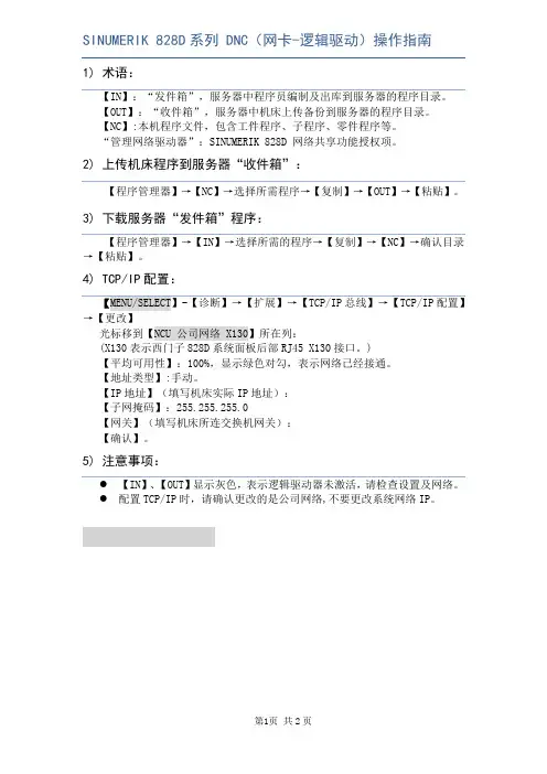
SINUMERIK 828D系列 DNC(网卡-逻辑驱动)操作指南1)术语:【IN】:“发件箱”,服务器中程序员编制及出库到服务器的程序目录。
【OUT】:“收件箱”,服务器中机床上传备份到服务器的程序目录。
【NC】:本机程序文件,包含工件程序、子程序、零件程序等。
“管理网络驱动器”:SINUMERIK 828D 网络共享功能授权项。
2)上传机床程序到服务器“收件箱”:【程序管理器】→【NC】→选择所需程序→【复制】→【OUT】→【粘贴】。
3)下载服务器“发件箱”程序:【程序管理器】→【IN】→选择所需的程序→【复制】→【NC】→确认目录→【粘贴】。
4)TCP/IP配置:光标移到【NCU 公司网络 X130】所在列:(X130表示西门子828D系统面板后部RJ45 X130接口。
)【平均可用性】:100%,显示绿色对勾,表示网络已经接通。
【地址类型】:手动。
【IP地址】(填写机床实际IP地址):【子网掩码】:255.255.255.0【网关】(填写机床所连交换机网关):【确认】。
5)注意事项:●【IN】、【OUT】显示灰色,表示逻辑驱动器未激活,请检查设置及网络。
●配置TCP/IP时,请确认更改的是公司网络,不要更改系统网络IP。
SINUMERIK 828D系统参数设置1.公司网络IP设置→【更改】光标移到【NCU 公司网络 X130】所在列:(X130表示西门子828D系统面板后部RJ45 X130接口。
)【平均可用性】:100%,显示绿色对勾,表示网络已经接通。
【地址类型】:手动。
【IP地址】(填写机床实际IP地址):【子网掩码】:255.255.255.0【网关】(填写机床所连交换机网关):【确认】。
2.逻辑驱动器设置【MENU/SELECT】→[调试]-[HMI]-[右扩展]-[授权]-[全部选件-[Page Down]*2“管理网络驱动器-6FC5800-0AM78-0YB0“(示例)【已设置】【已授权】。
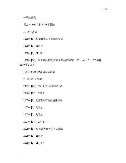
一系统参数后台:Alt+N或者shift+报警键1、通用数据10000【0】X(定义机床坐标轴的名称10000【1】Z(同上10000【2】SP(同上10000【3-5】自由轴的名称(无定义轴的名称X1、Y1、A1、B1、SP等等11310 手轮反向11346 手轮脉冲移动实际距离2、通道机床参数20050【0-3】0(定义通道内的几何轴20060【0-3】0(同上20070【0】1(通道内有效的机床轴号20070【1】2(同上20070【2】3(同上20070【3-4】0(同上20080【0】X(通道内有效的机床轴名20080【1】Z(同上20080【2】SP(同上20080【3-4】0(同上20700 0(未回参考点NC启动停止为13、轴参数通过“轴+”“轴-”更换轴,使用的同性质轴同时更改30100【5】1(模拟给定输出到轴控接口30110【1】1-驱动器号对于X轴(定义速度给定端口30110【2】2-驱动器号对于Z轴(同上30130【0】1(给定值输出类型,同时更改30220 同30110,实际值:驱动器号(定义位置反馈接口30240 1-实际值(编码器反馈类型,同时更改,1-相对编码器/2-仿真轴/4-绝对编码器30300 1(定义“回转轴”对于SP30310 1(回转轴取模转换,对于SP30320 1(取模360度位置显示,1为有效,对于SP31020 2048(每转的编码器线数,对于SP31030 10(丝杠螺距31040 1-直接测量系统32110 1-实际值(反馈记性:1/-131050【0-5】1(减速箱丝杠端齿轮齿数31060【0-5】5(减速箱电机端齿轮齿数32000 3000(最大轴速度,同时更改32010 2500(点动方式快速速度32100 电机转向(1/-132110 反馈极性(1/-132450 反向间隙补偿,回参考点后补偿生效(单位mm 36100 负方向软限位(单位mm,一般为负值36110 正方向软限位(单位mm,一般为正值设定主轴步骤如下:30300 1-定义为主轴(0-坐标轴/1-主轴30310 1-回转轴取模转换30320 1-取模360度位置显示(1-有效/0-无效35000 1-定义机床轴为主轴35100 实际值(最高主轴转速35110【0-5】主轴各档最高转速35120【0-5】主轴各档最低转速35130【0-5】主轴各档最高转速限制35140【0-5】主轴各档最低转速限制36200【0-5】各档速度监控的门限值带直接编码器的模拟量主轴30110 1-给定值模块号30220 1-编码器模块号30230 2-编码器信号端口号31000 实际值(0-编码器/1-光栅尺31010 实际值(光栅尺节点距离31020 实际值(编码器没转脉冲数NCK复位上电二驱动调试见手册14510【16】1H(用户数据车床14512【18】8H(用户数据K1使能。
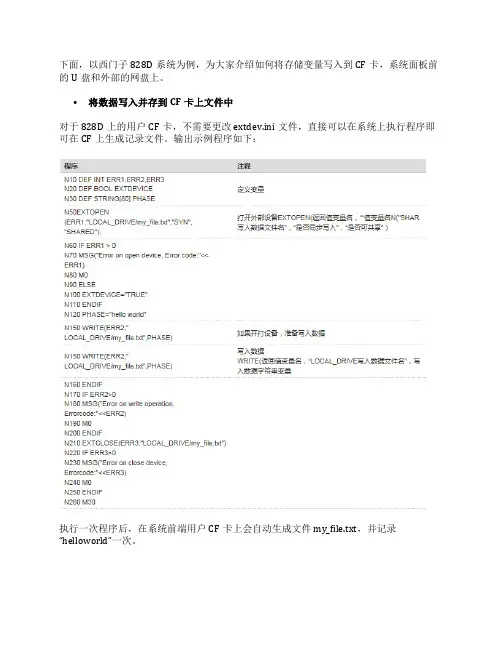
下面,以西门子828D系统为例,为大家介绍如何将存储变量写入到CF卡,系统面板前的U盘和外部的网盘上。
•将数据写入并存到CF卡上文件中
对于828D上的用户CF卡,不需要更改extdev.ini文件,直接可以在系统上执行程序即可在CF上生成记录文件。
输出示例程序如下:
执行一次程序后,在系统前端用户CF卡上会自动生成文件my_file.txt,并记录“helloworld”一次。
•将数据写入并保存到系统前面板的U盘上
对于828D的USB接口,需要按外部设备设置,就需要设置extdev.ini文件,把系统CF 中的“…/siemens/sinumerik/nck/extdev.ini”拷入“…/oem/sinumerik/nck/”,如下图:
并修改如下:
注意格式更改完成后,828D断电重新启动。
输出示例程序如下:
然后可以得到:
•将数据写入并存到网盘上的文件中
此方法的前提是设置好828D的网盘,这里不再赘述,可参阅828D简明调试手册。
接下来,方法同USB类似,首先设置extdev.ini文件,如下图:
注意格式更改完成后,828D断电重新启动。
含义如下:
/dev/ext/1=” //PC机的用户名%PC机密码@PC机IP地址/共享文件夹名称,/要写入数据的文件名称,A”
输出示例程序如下:
然后可以得到:。
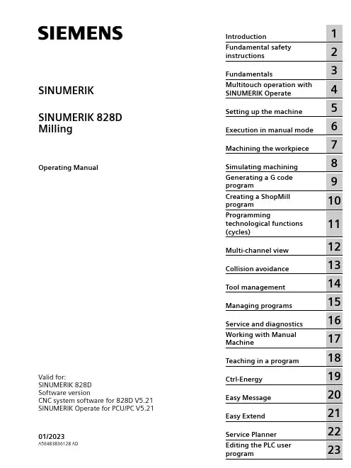
SINUMERIK SINUMERIK 828D MillingOperating ManualValid for:SINUMERIK 828DSoftware versionCNC system software for 828D V5.21 SINUMERIK Operate for PCU/PC V5.2101/2023A5E48383612B ADLegal information Warning notice systemThis manual contains notices you have to observe in order to ensure your personal safety, as well as to prevent damage to property. The notices referring to your personal safety are highlighted in the manual by a safety alert symbol, notices referring only to property damage have no safety alert symbol. These notices shown below aregraded according to the degree of danger.DANGERindicates that death or severe personal injury will result if proper precautions are not taken.WARNINGindicates that death or severe personal injury may result if proper precautions are not taken.CAUTIONindicates that minor personal injury can result if proper precautions are not taken.NOTICEindicates that property damage can result if proper precautions are not taken.If more than one degree of danger is present, the warning notice representing the highest degree of danger will be used. A notice warning of injury to persons with a safety alert symbol may also include a warning relating to property damage.Qualified PersonnelThe product/system described in this documentation may be operated only bypersonnel qualified for the specific task in accordance with the relevant documentation, in particular its warning notices and safety instructions. Qualified personnel are those who, based on their training and experience, are capable of identifying risks and avoiding potential hazards when working with these products/systems.Proper use of Siemens productsNote the following:WARNINGSiemens products may only be used for the applications described in the catalog and in the relevant technical documentation. If products and components from other manufacturers are used, these must be recommended or approved by Siemens. Proper transport, storage, installation, assembly, commissioning, operation and maintenance are required to ensure that the products operate safely and without any problems. The permissible ambient conditions must be complied with. The information in the relevant documentation must be observed.TrademarksAll names identified by ® are registered trademarks of Siemens AG. The remaining trademarks in this publication may be trademarks whose use by third parties for their own purposes could violate the rights of the owner.Disclaimer of LiabilityWe have reviewed the contents of this publication to ensure consistency with the hardware and software described. Since variance cannot be precluded entirely, we cannot guarantee full consistency. However, the information in this publication is reviewed regularly and any necessary corrections are included in subsequent editions.Siemens AGDigital Industries Postfach 48 4890026 NÜRNBERG GERMANYA5E48383612B ADⓅ 05/2023 Subject to change Copyright © Siemens AG 2008 - 2023.All rights reservedTable of contents1Introduction (19)1.1About SINUMERIK (19)1.2About this documentation (20)1.3Documentation on the internet (21)1.3.1Documentation overview SINUMERIK 828D (21)1.3.2Documentation overview SINUMERIK operator components (21)1.4Feedback on the technical documentation (23)1.5mySupport documentation (24)1.6Service and Support (25)1.7Compliance with the General Data Protection Regulation (27)1.8Using OpenSSL (28)2Fundamental safety instructions (29)2.1General safety instructions (29)2.2Warranty and liability for application examples (30)2.3Security information (31)3Fundamentals (33)3.1Product overview (33)3.2Operator panel fronts (34)3.2.1Overview (34)3.2.2Keys of the operator panel (36)3.3Machine control panels (44)3.3.1Overview (44)3.3.2Controls on the machine control panel (44)3.4User interface (48)3.4.1Screen layout (48)3.4.2Status display (49)3.4.3Actual value window (51)3.4.4T,F,S window (53)3.4.5Operation via softkeys and buttons (55)3.4.6Entering or selecting parameters (56)3.4.7Pocket calculator (58)3.4.8Pocket calculator functions (59)3.4.9Context menu (61)3.4.10Changing the user interface language (61)3.4.11Entering Chinese characters (62)3.4.11.1Function - input editor (62)3.4.11.2Entering Asian characters (64)3.4.11.3Editing the dictionary (65)MillingOperating Manual, 01/2023, A5E48383612B AD3Table of contents3.4.12Entering Korean characters (66)3.4.13Protection levels (69)3.4.14Work station safety (71)3.4.15Cleaning mode (71)3.4.16Online help in SINUMERIK Operate (71)4Multitouch operation with SINUMERIK Operate (75)4.1Multitouch panels (75)4.2Touch-sensitive user interface (76)4.3Finger gestures (77)4.4Multitouch user interface (80)4.4.1Screen layout (80)4.4.2Function key block (81)4.4.3Further operator touch controls (81)4.4.4Virtual keyboard (82)4.4.5Special "tilde" character (83)4.5Expansion with side screen (84)4.5.1Overview (84)4.5.2Sidescreen with standard windows (84)4.5.3Standard widgets (86)4.5.4"Actual value" widget (86)4.5.5"Zero point" widget (87)4.5.6"Alarms" widget (87)4.5.7"NC/PLC variables" widget (87)4.5.8"Axle load" widget (88)4.5.9"Tool" widget (88)4.5.10"Service life" widget (89)4.5.11"Program runtime" widget (89)4.5.12Widget "Camera 1" and "Camera 2" (89)4.5.13Sidescreen with pages for the ABC keyboard and/or machine control panel (90)4.5.14Example 1: ABC keyboard in the sidescreen (91)4.5.15Example 2: Machine control panel in the sidescreen (92)5Setting up the machine (93)5.1Switching on and switching off (93)5.2Approaching a reference point (94)5.2.1Referencing axes (94)5.2.2User agreement (95)5.3Operating modes (97)5.3.1General (97)5.3.2Modes groups and channels (99)5.3.3Channel switchover (99)5.4Settings for the machine (101)5.4.1Switching over the coordinate system (MCS/WCS) (101)5.4.2Switching the unit of measurement (101)5.4.3Setting the zero offset (103)5.5Measure tool (105)5.5.1Overview (105)Milling 4Operating Manual, 01/2023, A5E48383612B ADTable of contents5.5.2Manually measuring drilling and milling tools (105)5.5.3Measuring drilling and milling tools with the workpiece reference point (106)5.5.4Measuring drilling and milling tools with fixed reference point (107)5.5.5Measuring radius or diameter (108)5.5.6Fixed point calibration (109)5.5.7Measuring the drilling and milling tool length with electrical tool probe (109)5.5.8Calibrating the electrical tool probe (112)5.5.9Manually measuring a turning tool (for milling/turning machine) (113)5.5.10Manually measuring a turning tool using a tool probe (for milling/turning machine) (114)5.5.11Logging tool measurement results (116)5.6Measuring the workpiece zero (117)5.6.1Overview (117)5.6.2Sequence of operations (121)5.6.3Examples with manual swiveling (swiveling in JOG mode) (122)5.6.4Setting the edge (123)5.6.5Edge measurement (124)5.6.6Measuring a corner (129)5.6.7Measuring a pocket and hole (132)5.6.8Measuring a spigot (135)5.6.9Aligning the plane (140)5.6.10Defining the measurement function selection (143)5.6.11Logging measurement results for the workpiece zero (144)5.6.12Calibrating the electronic workpiece probe (145)5.6.12.1Calibration of length and radius or diameter (145)5.6.12.2Calibrate on sphere (146)5.7Settings for the measurement result log (148)5.8Zero offsets (150)5.8.1Overview - work offsets (150)5.8.2Display active zero offset (151)5.8.3Displaying the zero offset "overview" (151)5.8.4Displaying and editing base zero offset (153)5.8.5Displaying and editing settable zero offset (154)5.8.6Displaying and editing details of the zero offsets (154)5.8.7Deleting a zero offset (156)5.8.8Measuring the workpiece zero (157)5.9Monitoring axis and spindle data (158)5.9.1Specify working area limitations (158)5.9.2Editing spindle data (158)5.10Displaying setting data lists (160)5.11Handwheel assignment (161)5.12MDA (163)5.12.1Working in MDA (163)5.12.2Saving an MDA program (163)5.12.3Editing/executing a MDI program (164)5.12.4Deleting an MDA program (165)6Execution in manual mode (167)6.1General (167)MillingOperating Manual, 01/2023, A5E48383612B AD5Table of contents6.2Selecting a tool and spindle (168)6.2.1T, S, M windows (168)6.2.2Selecting a tool (170)6.2.3Starting and stopping a spindle manually (170)6.2.4Position spindle (171)6.3Traversing axes (173)6.3.1Traverse axes by a defined increment (173)6.3.2Traversing axes by a variable increment (174)6.4Positioning axes (175)6.5Swiveling (176)6.6Manual retraction (181)6.7Simple face milling of the workpiece (182)6.8Simple workpiece machining operations with milling/turning machines (185)6.8.1Simple workpiece face milling (milling/turning machine) (185)6.8.2Simple stock removal of workpiece (for milling/turning machine) (187)6.9Default settings for manual mode (191)7Machining the workpiece (193)7.1Starting and stopping machining (193)7.2Selecting a program (195)7.3Testing a program (196)7.4Displaying the current program block (197)7.4.1Displaying a basic block (197)7.4.2Display program level (197)7.5Correcting a program (199)7.6Repositioning axes (200)7.7Starting machining at a specific point (201)7.7.1Use block search (201)7.7.2Continuing program from search target (203)7.7.3Simple search target definition (203)7.7.4Defining an interruption point as search target (204)7.7.5Entering the search target via search pointer (205)7.7.6Parameters for block search in the search pointer (206)7.7.7Block search mode (206)7.7.8Block search for position pattern (209)7.8Controlling the program run (211)7.8.1Program control (211)7.8.2Use Powerride for program control (213)7.8.3Skip blocks (214)7.9Overstore (215)7.10Editing a program (217)7.10.1Searching in programs (217)7.10.2Replacing program text (219)7.10.3Copying/pasting/deleting a program block (220)Milling 6Operating Manual, 01/2023, A5E48383612B ADTable of contents7.10.4Renumbering a program (222)7.10.5Creating a program block (223)7.10.6Opening additional programs (224)7.10.7Editor settings (225)7.11Working with DXF files (229)7.11.1Overview (229)7.11.2Displaying CAD drawings (230)7.11.2.1Open a DXF file (230)7.11.2.2Cleaning a DXF file (230)7.11.2.3Enlarging or reducing the CAD drawing (231)7.11.2.4Changing the section (232)7.11.2.5Rotating the view (232)7.11.2.6Displaying/editing information for the geometric data (233)7.11.3Importing and editing a DXF file in the editor (234)7.11.3.1General procedure (234)7.11.3.2Specifying a reference point (234)7.11.3.3Assigning the machining plane (235)7.11.3.4Setting the tolerance (235)7.11.3.5Selecting the machining range / deleting the range and element (236)7.11.3.6Saving the DXF file (237)7.11.3.7Transferring the drilling positions (238)7.11.3.8Accepting contours (240)7.12Importing shapes from CAD programs (244)7.12.1Reading in CAD data into an editor and processing (246)7.12.1.1General procedure (246)7.12.1.2Import from CAD (246)7.12.1.3Defining reference points (247)7.12.1.4Viewing point information (250)7.12.1.5Creating a new contour (251)7.12.1.6Accepting the machining steps (252)7.13Display and edit user variables (254)7.13.1Overview (254)7.13.2Global R parameters (255)7.13.3R parameters (256)7.13.4Displaying global user data (GUD) (258)7.13.5Displaying channel GUDs (259)7.13.6Displaying local user data (LUD) (260)7.13.7Displaying program user data (PUD) (261)7.13.8Searching for user variables (261)7.14Displaying G Functions and Auxiliary Functions (264)7.14.1Selected G functions (264)7.14.2All G functions (266)7.14.3G functions for mold making (266)7.14.4Auxiliary functions (267)7.15Displaying superimpositions (269)7.16Mold making view (272)7.16.1Overview (272)7.16.2Starting the mold making view (274)7.16.3Adapting the mold making view (274)MillingOperating Manual, 01/2023, A5E48383612B AD7Table of contents7.16.4Specifically jump to the program block (275)7.16.5Searching for program blocks (276)7.16.6Changing the view (277)7.16.6.1Enlarging or reducing the graphical representation (277)7.16.6.2Moving and rotating the graphic (278)7.16.6.3Modifying the viewport (278)7.17Displaying the program runtime and counting workpieces (280)7.18Setting for automatic mode (282)8Simulating machining (285)8.1Overview (285)8.2Simulation before machining of the workpiece (293)8.3Simultaneous recording before machining of the workpiece (294)8.4Simultaneous recording during machining of the workpiece (295)8.5Different views of the workpiece (296)8.5.1Plan view (296)8.5.23D view (297)8.5.3Side view (297)8.5.4Turning view (298)8.5.5Half section (298)8.6Editing the simulation display (300)8.6.1Blank display (300)8.6.2Showing and hiding the tool path (300)8.7Program control during the simulation (301)8.7.1Changing the feedrate (301)8.7.2Simulating the program block by block (302)8.8Changing and adapting a simulation graphic (303)8.8.1Enlarging or reducing the graphical representation (303)8.8.2Panning a graphical representation (304)8.8.3Rotating the graphical representation (304)8.8.4Modifying the viewport (305)8.8.5Defining cutting planes (305)8.9Displaying simulation alarms (307)9Generating a G code program (309)9.1Graphical programming (309)9.2Program views (310)9.3Program structure (314)9.4Fundamentals (315)9.4.1Machining planes (315)9.4.2Current planes in cycles and input screens (315)9.4.3Programming a tool (T) (316)9.5Generating a G code program (317)9.6Blank input (318)Milling 8Operating Manual, 01/2023, A5E48383612B ADTable of contents9.7Machining plane, milling direction, retraction plane, safe clearance and feedrate (PL, RP,SC, F) (320)9.8Selection of the cycles via softkey (321)9.9Calling technology functions (325)9.9.1Hiding cycle parameters (325)9.9.2Setting data for cycles (325)9.9.3Checking cycle parameters (325)9.9.4Programming variables (326)9.9.5Changing a cycle call (326)9.9.6 Compatibility for cycle support (327)9.9.7Additional functions in the input screens (327)9.10Measuring cycle support (328)10Creating a ShopMill program (329)10.1Program views (330)10.2Program structure (335)10.3Fundamentals (336)10.3.1Machining planes (336)10.3.2Polar coordinates (336)10.3.3Absolute and incremental dimensions (337)10.4Creating a ShopMill program (340)10.5Program header (341)10.6Program header (for milling/turning machine) (343)10.7Generating program blocks (346)10.8Tool, offset value, feed and spindle speed (T, D, F, S, V) (347)10.9Defining machine functions (349)10.10Call work offsets (351)10.11Repeating program blocks (352)10.12Specifying the number of workpieces (354)10.13Changing program blocks (355)10.14Changing program settings (356)10.15Selection of the cycles via softkey (358)10.16Calling technology functions (363)10.16.1Additional functions in the input screens (363)10.16.2Checking input parameters (363)10.16.3Setting data for technological functions (363)10.16.4Changing a cycle call (364)10.16.5Programming variables (364)10.16.6 Compatibility for cycle support (365)10.17Measuring cycle support (366)10.18Example, standard machining (367)10.18.1Workpiece drawing (368)MillingOperating Manual, 01/2023, A5E48383612B AD9Table of contents10.18.2Programming (368)10.18.3Results/simulation test (380)10.18.4G code machining program (382)11Programming technological functions (cycles) (385)11.1Know-how protection (385)11.2Drilling (386)11.2.1General (386)11.2.2Centering (CYCLE81) (387)11.2.3Drilling (CYCLE82) (388)11.2.4Reaming (CYCLE85) (392)11.2.5Deep-hole drilling 1 (CYCLE83) (393)11.2.6Deep-hole drilling 2 (CYCLE830) (399)11.2.7Boring (CYCLE86) (409)11.2.8Tapping (CYCLE84, 840) (411)11.2.9Drill and thread milling (CYCLE78) (418)11.2.10Positioning and position patterns (422)11.2.11Arbitrary positions (CYCLE802) (424)11.2.12Row position pattern (HOLES1) (427)11.2.13Grid or frame position pattern (CYCLE801) (428)11.2.14Circle or pitch circle position pattern (HOLES2) (430)11.2.15Displaying and hiding positions (432)11.2.16Repeating positions (434)11.3Milling (435)11.3.1Face milling (CYCLE61) (435)11.3.2Rectangular pocket (POCKET3) (437)11.3.3Circular pocket (POCKET4) (444)11.3.4Rectangular spigot (CYCLE76) (451)11.3.5Circular spigot (CYCLE77) (456)11.3.6Multi-edge (CYCLE79) (460)11.3.7Longitudinal groove (SLOT1) (464)11.3.8Circumferential groove (SLOT2) (470)11.3.9Open groove (CYCLE899) (476)11.3.10Long hole (LONGHOLE) - only for G code programs (485)11.3.11Thread milling (CYCLE70) (487)11.3.12Engraving (CYCLE60) (491)11.4Contour milling (498)11.4.1General (498)11.4.2Representation of the contour (498)11.4.3Creating a new contour (500)11.4.4Creating contour elements (501)11.4.5Changing the contour (506)11.4.6Contour call (CYCLE62) - only for G code program (507)11.4.7Path milling (CYCLE72) (508)11.4.8Contour pocket/contour spigot (CYCLE63/64) (513)11.4.9Predrilling contour pocket (CYCLE64) (515)11.4.10Milling contour pocket (CYCLE63) (518)11.4.11Residual material contour pocket (CYCLE63) (523)11.4.12Milling contour spigot (CYCLE63) (524)11.4.13Residual material contour spigot (CYCLE63) (528)Milling 10Operating Manual, 01/2023, A5E48383612B ADTable of contents 11.5Turning - milling/turning machine (531)11.5.1General (531)11.5.2Stock removal (CYCLE951) (531)11.5.3Groove (CYCLE930) (535)11.5.4Undercut form E and F (CYCLE940) (539)11.5.5Thread undercut (CYCLE940) (545)11.5.6Thread turning (CYCLE99), only for G code (551)11.5.6.1Special aspects of the selection alternatives for infeed depths (578)11.5.7Thread chain (CYCLE98) (579)11.5.7.1Special aspects of the selection alternatives for infeed depths (588)11.5.8Cut-off (CYCLE92) (589)11.6Contour turning - Milling/turning machine (593)11.6.1General information (593)11.6.2Representation of the contour (594)11.6.3Creating a new contour (595)11.6.4Creating contour elements (597)11.6.5Changing the contour (604)11.6.6Contour call (CYCLE62) (605)11.6.7Stock removal (CYCLE952) (606)11.6.8Stock removal residual (CYCLE952) (621)11.6.9Grooving (CYCLE952) (624)11.6.10Grooving residual material (CYCLE952) (635)11.6.11Plunge turning (CYCLE952) (639)11.6.12Plunge turning residual material (CYCLE952) (649)11.7Further cycles and functions (654)11.7.1Swivel plane (CYCLE800) (654)11.7.1.1Cylinder surface transformation with swivel plane (661)11.7.2Swiveling tool (CYCLE800) (665)11.7.2.1Swiveling tool/preloading milling tools - only for G code program (CYCLE800) (665)11.7.2.2Aligning turning tools (CYCLE800) - millling/turning machine (666)11.7.3High-speed settings (CYCLE832) (671)11.7.4Subroutines (675)11.7.5Surface turning (CYCLE953) (677)11.7.6Adapt to load (CYCLE782) (679)11.7.7Interpolation turning (CYCLE806) (681)11.7.7.1Function (681)11.7.7.2Selecting/deselecting interpolation turning - CYCLE806 (682)11.7.7.3Calling the cycle (683)11.7.7.4Parameter (683)11.8Additional cycles and functions in ShopMill (684)11.8.1Transformations (684)11.8.2Translation (685)11.8.3Rotation (685)11.8.4Scaling (686)11.8.5Mirroring (687)11.8.6Cylinder surface transformation (687)11.8.7Straight or circular machining (690)11.8.8Programming a straight line (692)11.8.9Programming a circle with known center point (693)11.8.10Programming a circle with known radius (694)Table of contents11.8.11Helix (695)11.8.12Polar coordinates (696)11.8.13Straight polar (697)11.8.14Circle polar (697)11.8.15Obstacle (698)12Multi-channel view (701)12.1Multi-channel view (701)12.2Multi-channel view in the "Machine" operating area (702)12.3Multi-channel view for large operator panels (705)12.4Setting the multi-channel view (707)13Collision avoidance (709)13.1Collision avoidance (709)13.2Activate collision avoidance (711)13.3Set collision avoidance (712)14Tool management (715)14.1Lists for the tool management (715)14.2Magazine management (717)14.3Tool types (718)14.4Tool dimensioning (721)14.5Tool list (728)14.5.1Additional data (731)14.5.2Creating a new tool (732)14.5.3Measuring the tool (734)14.5.4Managing several cutting edges (734)14.5.5Delete tool (735)14.5.6Loading and unloading tools (735)14.5.7Selecting a magazine (737)14.5.8Managing a tool in a file (738)14.6Tool wear (741)14.6.1Reactivating a tool (743)14.7Tool data OEM (745)14.8Magazine (746)14.8.1Positioning a magazine (748)14.8.2Relocating a tool (748)14.8.3Deleting / unloading / loading / relocating all tools (749)14.9Tool details (751)14.9.1Displaying tool details (751)14.9.2Tool data (751)14.9.3Cutting edge data (752)14.9.4Monitoring data (754)14.10Changing a tool type (755)14.11Graphic display (756)Table of contents14.12Sorting tool management lists (758)14.13Filtering the tool management lists (759)14.14Specific search in the tool management lists (761)14.15Multiple selection in the tool management lists (763)14.16Settings for tool lists (764)14.17Working with Multitool (765)14.17.1Tool list for multitool (765)14.17.2Create multitool (766)14.17.3Equipping multitool with tools (768)14.17.4Removing a tool from multitool (769)14.17.5Deleting multitool (770)14.17.6Loading and unloading multitool (770)14.17.7Reactivating the multitool (771)14.17.8Relocating a multitool (772)14.17.9Positioning a multitool (773)15Managing programs (775)15.1Overview (775)15.1.1Program management (775)15.1.2NC memory (778)15.1.3Local drive (778)15.1.4USB drives (779)15.1.5FTP drive (780)15.2Opening and closing the program (782)15.3Executing a program (784)15.4Creating a directory / program / job list / program list (786)15.4.1File and directory names (786)15.4.2Creating a new directory (786)15.4.3Creating a new workpiece (787)15.4.4Creating a new G code program (788)15.4.5Creating a new ShopMill program (788)15.4.6Storing any new file (789)15.4.7Creating a job list (790)15.4.8Creating a program list (792)15.5Creating templates (793)15.6Searching directories and files (794)15.7Displaying the program in the Preview (796)15.8Selecting several directories/programs (797)15.9Copying and pasting a directory/program (799)15.10Deleting a program/directory (801)15.10.1Deleting a program/directory (801)15.11Changing file and directory properties (802)15.12Set up drives (804)15.12.1Overview (804)Table of contents15.12.2Setting up drives (804)15.13Viewing PDF documents (810)15.14EXTCALL (813)15.15Execution from external memory (EES) (815)15.16Backing up data (816)15.16.1Generating an archive in the Program Manager (816)15.16.2Generating an archive via the system data (817)15.16.3Reading in an archive in the Program Manager (819)15.16.4Read in archive from system data (820)15.17Setup data (822)15.17.1Backing up setup data (822)15.17.2Reading-in set-up data (824)15.18Recording tools and determining the demand (826)15.18.1Overview (826)15.18.2Opening tool data (827)15.18.3Checking the loading (827)15.19Backing up parameters (829)15.20Multiple clamping (832)15.20.1Multiple clamping (832)15.20.2Program header setting, "Clamping" (833)15.20.3Creating a multiple clamping program (834)16Service and diagnostics (837)16.1Alarm, error, and system messages (837)16.1.1Displaying alarms (837)16.1.2Displaying an alarm log (839)16.1.3Displaying messages (840)16.1.4Sorting, alarms, faults and messages (840)16.2PLC and NC variables (842)16.2.1Displaying and editing PLC and NC variables (842)16.2.2Saving and loading screen forms (846)16.3Creating screenshots (847)16.4Version (848)16.4.1Displaying version data (848)16.4.2Save information (849)16.5Logbook (851)16.5.1Displaying and editing the logbook (851)16.5.2Making a logbook entry (852)16.6Remote diagnostics (854)16.6.1Setting remote access (854)16.6.2Permit modem (855)16.6.3Request remote diagnostics (856)16.6.4Exit remote diagnostics (857)17Working with Manual Machine (859)17.1Manual Machine (859)Table of contents17.2Measuring the tool (861)17.3Measuring the workpiece zero (862)17.4Setting the zero offset (863)17.5Set limit stop (864)17.6Simple workpiece machining (865)17.6.1Traversing axes (865)17.6.2Angular milling (866)17.6.3Straight and circular machining (867)17.6.3.1Straight milling (867)17.6.3.2Circular milling (868)17.7More complex machining (870)17.7.1Drilling with Manual Machine (871)17.7.2Milling with Manual Machine (872)17.7.3Contour milling with manual machine (873)17.7.4Turning with manual machine - milling/turning machine (873)17.8Simulation and simultaneous recording (875)18Teaching in a program (877)18.1Overview (877)18.2Select teach in mode (879)18.3Processing a program (880)18.3.1Inserting a block (880)18.3.2Editing a block (880)18.3.3Selecting a block (881)18.3.4Deleting a block (881)18.4Teach sets (883)18.4.1Input parameters for teach-in blocks (884)18.5Settings for teach-in (886)19Ctrl-Energy (887)19.1Functions (887)19.2Ctrl-E analysis (888)19.2.1Displaying energy consumption (888)19.2.2Displaying the energy analyses (889)19.2.3Measuring and saving the energy consumption (890)19.2.4Tracking measurements (891)19.2.5Tracking usage values (891)19.2.6Comparing usage values (892)19.2.7Long-term measurement of the energy consumption (893)19.3Ctrl-E profiles (894)19.3.1Using the energy-saving profile (894)20Easy Message (897)20.1Overview (897)20.2Activating Easy Message (898)Table of contents20.3Creating/editing a user profile (899)20.4Setting-up events (901)20.5Logging an active user on and off (903)20.6Displaying SMS logs (904)20.7Making settings for Easy Message (905)21Easy Extend (907)21.1Overview (907)21.2Enabling a device (908)21.3Activating and deactivating a device (909)21.4Initial commissioning of additional devices (910)22Service Planner (911)22.1Performing and monitoring maintenance tasks (911)23Editing the PLC user program (913)23.1Introduction (913)23.2Displaying and editing PLC properties (914)23.2.1Displaying PLC properties (914)23.2.2Resetting the processing time (914)23.2.3Loading modified PLC user program (914)23.3Displaying and editing PLC and NC variables (916)23.4Displaying and editing PLC signals in the status list (921)23.5View of the program blocks (922)23.5.1Displaying information on the program blocks (922)23.5.2Structure of the user interface (923)23.5.3Control options (924)23.5.4Displaying the program status (925)23.5.5Changing the address display (926)23.5.6Enlarging/reducing the ladder diagram (926)23.5.7Program block (927)23.5.7.1Displaying and editing the program block (927)23.5.7.2Displaying local variable table (928)23.5.7.3Creating a program block (928)23.5.7.4Opening a program block in the window (930)23.5.7.5Displaying/canceling the access protection (930)23.5.7.6Editing block properties subsequently (931)23.5.8Editing a program block (931)23.5.8.1Editing the PLC user program (931)23.5.8.2Editing a program block (932)23.5.8.3Deleting a program block (934)23.5.8.4Inserting and editing networks (934)23.5.8.5Editing network properties (935)23.5.9Displaying the network symbol information table (936)23.6Displaying symbol tables (938)。
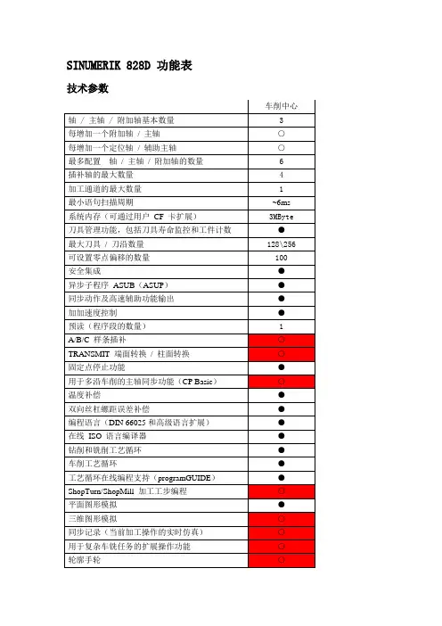
SINUMERIK 828D 功能表技术参数车削中心轴 / 主轴 / 附加轴基本数量 3每增加一个附加轴/ 主轴○每增加一个定位轴/ 辅助主轴○最多配置轴/ 主轴/ 附加轴的数量 6插补轴的最大数量 4加工通道的最大数量 1最小语句扫描周期~6ms 系统内存(可通过用户CF 卡扩展)3MByte 刀具管理功能,包括刀具寿命监控和工件计数●最大刀具/ 刀沿数量128\256 可设置零点偏移的数量100 安全集成●异步子程序ASUB(ASUP)●同步动作及高速辅助功能输出●加加速度控制●预读(程序段的数量) 1A/B/C 样条插补○TRANSMIT 端面转换/ 柱面转换○固定点停止功能●用于多沿车削的主轴同步功能(CP Basic)○温度补偿●双向丝杠螺距误差补偿●编程语言(DIN 66025和高级语言扩展)●在线ISO 语言编译器●钻削和铣削工艺循环●车削工艺循环●工艺循环在线编程支持(programGUIDE)●ShopTurn/ShopMill 加工工步编程○平面图形模拟●三维图形模拟○同步记录(当前加工操作的实时仿真)○用于复杂车铣任务的扩展操作功能○轮廓手轮○集成基于SIMATIC S7-200 的PLC●内置梯形图查看器和编辑器●每条PLC命令的处理时间6µsPLC梯形图的最大步数24,000伺服同步高速PLC任务●过程事件的响应时间(终端到终端)<6ms数字量输入/ 输出的最大数量288\192模拟量输入/ 输出的最大数量8\8调试和服务功能自定义用户画面(Easy Screen):轻松创建用户画○面(多于5幅需要授权)维护计划:用于编排维护工作计划●机床选项管理(Easy Extend):管理机床部件●备份管理(Easy Archive):数据归档●●标配(基本功能)○ CNC选项–不可用。
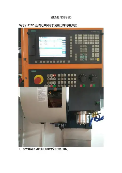
SIEMENS828D
西门子828D系统刀库回零及刷新刀库列表步骤:
1. 首先要到刀具列表卸载主轴上的刀具。
2. 选择< OFFSET >参数键。
3. 选择屏幕下方< > >扩展键。
4. 选择< Easy Extend > PLC开关。
5. 选择< 使能功能 >键。
6. 弹出输入密码对话窗,输入密码< 123456 >,并按< 确认 >键。
7. < 激活使能>。
8. 在手动方式选择< REF.POINT >回零方式、< 刀库使能 >按键,再按< 刀库回零 >键,这时刀库会正转直到当前刀号为1号刀套。
9. 再选择< OFFSET >参数键进去,选择< 取消激活 >。
10. 选择< PROGAM MANAGER >程序管理器,再找到< 子程序――MAG_CONT >文件并打开。
11. 选择屏幕下方的< 执行 >键。
12. 按< 循环启动 >执行程序,完成即可。
SINUMERIK 828D系列 DNC(网卡-逻辑驱动)操作指南1)术语:【IN】:“发件箱”,服务器中程序员编制及出库到服务器的程序目录。
【OUT】:“收件箱”,服务器中机床上传备份到服务器的程序目录。
【NC】:本机程序文件,包含工件程序、子程序、零件程序等。
“管理网络驱动器”:SINUMERIK 828D 网络共享功能授权项。
2)上传机床程序到服务器“收件箱”:【程序管理器】→【NC】→选择所需程序→【复制】→【OUT】→【粘贴】。
3)下载服务器“发件箱”程序:【程序管理器】→【IN】→选择所需的程序→【复制】→【NC】→确认目录→【粘贴】。
4)TCP/IP配置:光标移到【NCU 公司网络 X130】所在列:(X130表示西门子828D系统面板后部RJ45 X130接口。
)【平均可用性】:100%,显示绿色对勾,表示网络已经接通。
【地址类型】:手动。
【IP地址】(填写机床实际IP地址):【子网掩码】:255.255.255.0【网关】(填写机床所连交换机网关):【确认】。
5)注意事项:●【IN】、【OUT】显示灰色,表示逻辑驱动器未激活,请检查设置及网络。
●配置TCP/IP时,请确认更改的是公司网络,不要更改系统网络IP。
SINUMERIK 828D系统参数设置1.公司网络IP设置→【更改】光标移到【NCU 公司网络 X130】所在列:(X130表示西门子828D系统面板后部RJ45 X130接口。
)【平均可用性】:100%,显示绿色对勾,表示网络已经接通。
【地址类型】:手动。
【IP地址】(填写机床实际IP地址):【子网掩码】:255.255.255.0【网关】(填写机床所连交换机网关):【确认】。
2.逻辑驱动器设置【MENU/SELECT】→[调试]-[HMI]-[右扩展]-[授权]-[全部选件-[Page Down]*2“管理网络驱动器-6FC5800-0AM78-0YB0“(示例)【已设置】【已授权】。
SINUMERIK 828D 铣削编程简明教程51.钻削循环 (3)1.1钻中心孔(CYCLE81) (3)1.2浅孔钻削(CYCLE82) (5)1.3铰孔(CYCLE85) (6)1.4深孔钻削(CYCLE83) (7)1.5精镗孔(CYCLE86) (10)1.6攻丝(CYCLE84和CYCLE840) (11)2.作者信息 (13)1.1钻中心孔(CYCLE81)钻中心孔是在钻削加工中比较常见的加工工序。
为了保证在钻孔过程中孔的位置精度比较高,通常需要在钻孔之前安排一个钻削预定位孔的工序。
尤其在深孔钻削之前,为了防止钻头引偏尤为重要。
钻中心孔所用的刀具一般是钻尖角为90度的定心钻。
PL:选择加工平面。
通常这里都选择为G17(XY)。
在一般的立式或者卧式铣床上进行钻削加工都要选择G17平面。
即使是在车床的端面上进行钻孔,只要钻削加工的刀具轴线与机床的Z轴平行,就必须选择G17平面。
RP:钻孔完成之后刀具轴的定位高度。
SC:安全间隙。
相对于钻孔平面的距离。
Z0:孔上表面的绝对坐标。
这里的“单独位置”意味着当前的钻孔循环为非模态调用,即钻孔动作只在当前平面的当前位置上有效。
生成的代码形式为:CYCLE81(100,0,1,,25,0.6,0,1,11)。
如果将“单独位置”切换为“位置模式”,则在当前的位置上并不执行钻孔的动作,而是当刀具定位到后面——包含运动坐标的位置上,才会执行钻孔的动作。
同时,生成的代码格式为:MCALL CYCLE81(100,0,1,,25,0.6,0,1,11),在CYCLE81之前多出一个MCALL指令,这个“MCALL”代码表示钻孔循环进入模态调用的方式。
因此,只有在进入模态之后的坐标位置才可以成为钻孔的位置。
此时,如果没有在单独的程序行里写入不带任何参数的“MCALL”指令取消当前的模态,只要在后续的程序段中编写了坐标位置,那么机床运动到该位置后,仍然会继续执行当模式的钻孔动作。