自动化专业英语unit3
- 格式:ppt
- 大小:324.50 KB
- 文档页数:39
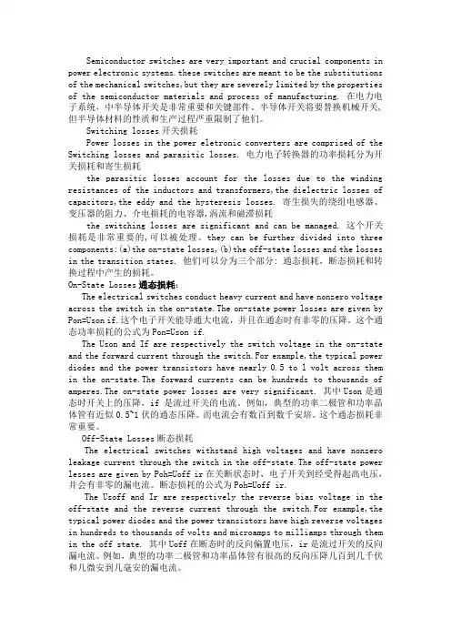
Semiconductor switches are very important and crucial components in power electronic systems.these switches are meant to be the substitutions of the mechanical switches,but they are severely limited by the properties of the semiconductor materials and process of manufacturing. 在电力电子系统,中半导体开关是非常重要和关键部件。
半导体开关将要替换机械开关,但半导体材料的性质和生产过程严重限制了他们。
Switching losses开关损耗Power losses in the power eletronic converters are comprised of the Switching losses and parasitic losses. 电力电子转换器的功率损耗分为开关损耗和寄生损耗the parasitic losses account for the losses due to the winding resistances of the inductors and transformers,the dielectric losses of capacitors,the eddy and the hysteresis losses. 寄生损失的绕组电感器、变压器的阻力、介电损耗的电容器,涡流和磁滞损耗the switching losses are significant and can be managed. 这个开关损耗是非常重要的,可以被处理。
they can be further divided into three components:(a)the on-state losses,(b)the off-state losses and the losses in the transition states. 他们可以分为三个部分: 通态损耗,断态损耗和转换过程中产生的损耗。
自动化专业常用英语词汇自动化是一门涉及机械、电子、计算机和控制系统等多个领域的学科,它致力于研究和开辟能够自动执行任务的系统和设备。
在自动化专业的学习和工作中,熟悉和掌握常用的英语词汇是非常重要的。
下面是自动化专业常用英语词汇的详细介绍。
1. Automation - 自动化Automation refers to the use of technology to control and operate a system or process without human intervention. It involves the use of various control systems, such as computers and robots, to perform tasks automatically.2. Control system - 控制系统A control system is a set of devices or software that manages and regulates the behavior of a system. It includes sensors, actuators, controllers, and communication networks that work together to maintain the desired performance of the system.3. Robotics - 机器人技术Robotics is the branch of technology that deals with the design, construction, and operation of robots. It involves the use of mechanical, electrical, and computer engineering principles to create machines that can perform tasks autonomously or with human assistance.4. Sensor - 传感器A sensor is a device that detects and responds to physical inputs, such as light, temperature, pressure, or motion. It converts these inputs into electrical signals that can be processed by a control system.5. Actuator - 执行器An actuator is a device that converts electrical, hydraulic, or pneumatic energy into mechanical motion. It is used to control or move a mechanism or system, such as opening or closing a valve or moving a robotic arm.6. Programmable Logic Controller (PLC) - 可编程逻辑控制器A programmable logic controller (PLC) is a specialized computer used to control and automate industrial processes. It is programmable and can be easily reconfigured to adapt to different tasks or requirements.7. Human-Machine Interface (HMI) - 人机界面The human-machine interface (HMI) is the user interface through which an operator interacts with a control system. It typically consists of a graphical display, buttons, and other input/output devices that allow the operator to monitor and control the system.8. Supervisory Control and Data Acquisition (SCADA) - 监控与数据采集系统Supervisory Control and Data Acquisition (SCADA) is a system used to monitor and control industrial processes. It collects real-time data from various sensors and devices and provides a graphical interface for operators to monitor and control the system.9. Industrial Internet of Things (IIoT) - 工业物联网The Industrial Internet of Things (IIoT) refers to the use of internet-connected devices and sensors in industrial settings to collect and exchange data. It enables real-time monitoring, analysis, and control of industrial processes, leading to improved efficiency and productivity.10. Machine Learning - 机器学习Machine learning is a subset of artificial intelligence that focuses on the development of algorithms and models that allow computers to learn and make predictions or decisions without being explicitly programmed. It is widely used in automation to improve system performance and decision-making.11. Control loop - 控制回路A control loop is a closed-loop system that continuously monitors and adjusts the output of a process to maintain a desired setpoint. It typically consists of a sensor, controller, and actuator that work together to regulate the system.12. Feedback - 反馈Feedback is the process of returning a portion of the output of a system back to the input for comparison and adjustment. It is used in control systems to continuously monitor and correct deviations from the desired performance.13. PID controller - 比例-积分-微分控制器A PID controller is a type of control algorithm that uses proportional, integral, and derivative actions to control a system. It is widely used in automation to achieve accurate and stable control of processes.14. Fault diagnosis - 故障诊断Fault diagnosis is the process of identifying and diagnosing faults or malfunctions in a system. It involves analyzing sensor data, system behavior, and performance to determine the cause of the problem and take appropriate corrective actions.15. Safety system - 安全系统A safety system is a set of measures and devices designed to prevent accidents and ensure the safety of personnel and equipment. It includes emergency stop buttons, safety interlocks, and protective barriers to minimize the risk of injury or damage.以上是自动化专业常用英语词汇的详细介绍。
可再生能源可再生能源的说明燃烧矿物质燃料提供能源是造成气候变化的主要的原因。
煤,油,天然气的燃烧产生的二氧化碳是其中主要的造成全球气候变暖的温室气体。
为了解决气候变化,找到一种将来使用的可持续的能源,我们急需采取更加有效的技术降低能源消耗,从能释放更少的甚至没有二氧化碳到大气中的可再生能源中获得能源。
可再生能源技术(像风,海浪,潮汐,水电,生物能——栽培和燃烧农作物所产生的能量)能提供清洁的无碳的能源作为矿物燃料(天然气,油,煤)的替代品。
他们通常用来加热和发电。
(生物能除外,尽管它释放二氧化碳,但它只是把植物一生光当中合作用所吸收的二氧化碳释放到空气中)。
与此相反,燃烧化石燃料会释放出地壳中锁藏了几十亿年的二氧化碳到大气中。
矿石能源的供给是有限的,也因此它们的持续利用是无法支撑到底的。
可再生技术是一种持可持续能源的产生办法,事实上,像风,海浪,太阳能等是不可能被耗尽的。
可再生能源可再生能源包括以下:太阳能太阳能给所有生命体提供最基本形式的能量。
太阳能是免费的,用之不竭的。
将太阳能转化成人类可以消耗的能源将产生成本。
几千年以来,太阳能一直被人们用来晒粮食或者为水,建筑物加热。
二十世纪采用的是将阳光直接转换为电能的光电技术。
风能空气的运动自古以来就被用作一种能源。
今天,先进的空气动力学研究已经研究出可以非常经济发电的风力涡轮机。
风力涡轮机常常被成组的放在位于乡间宽阔地带或沿海,山顶等常年有盛行风的农场。
地热能地壳下面的岩石包含了一直在衰减的放射性材料,像铀和钾。
这些材料持续不断的提高热能,在地球表面一万米以下的热能比世界上的所有的油气资源所含的能量多50000倍多。
地热能是发掘地壳下面的热量来加热水。
之后热水用来驱动电涡轮机加热建筑,具有最高地热的区域常位于活跃的或新形成的火山周围。
这些“热点”位于地壳构造边缘,这里的地壳很薄,足够热量通过。
许多这样的“热点”分布在太平洋沿岸。
水电在地球上,水既不能被创造,也不能被毁灭。
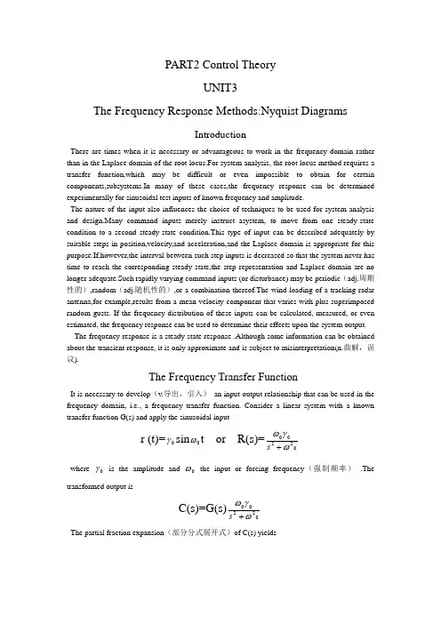
PART2 Control TheoryUNIT3The Frequency Response Methods:Nyquist DiagramsIntroductionThere are times when it is necessary or advantageous to work in the frequency domain rather than in the Laplace domain of the root locus.For system analysis, the root locus method requires a transfer function,which may be difficult or even impossible to obtain for certain components,subsystems.In many of these cases,the frequency response can be determined experimentally for sinusoidal test inputs of known frequency and amplitude.The nature of the input also influences the choice of techniques to be used for system analysis and design.Many command inputs merely instruct asystem, to move from one steady-state condition to a second steady-state condition.This type of input can be described adequately by suitable steps in position,velocity,and acceleration,and the Laplace domain is appropriate for this purpose.If,however,the interval between such step inputs is decreased so that the system never has time to reach the corresponding steady state,the step representation and Laplace domain are no longer adequate.Such rapidly varying command inputs (or disturbance) may be periodic (adj.周期性的),random (adj.随机性的),or a combination thereof.The wind loading of a tracking radar antenna,for example,results from a mean velocity component that varies with plus superimposed random gusts. If the frequency distribution of these inputs can be calculated, measured, or even estimated, the frequency response can be used to determine their effects upon the system output. The frequency response is a steady-state response .Although some information can be obtained about the transient response, it is only approximate and is subject to misinterpretation(n.曲解,误议).The Frequency Transfer FunctionIt is necessary to develop (v.导出,引入) an input-output relationship that can be used in the frequency domain, i.e., a frequency transfer function. Consider a linear system with a known transfer function G(s) and apply the sinusoidal inputr (t)=0γsin 0ωt or R(s)=02200ωγω+swhere 0γ is the amplitude and 0ω the input or forcing frequency (强制频率) .The transformed output is C(s)=G(s)02200ωγω+sThe partial fraction expansion (部分分式展开式)of C(s) yieldsC(s)=01ωj s C - +02ωj s C ++13γ+s C +243γ+s C +…Where -1γ,-2γ, … are the roots of the characteristic equation of the transfer function.The inverse transform isc(t)=t j e C 01ω+ t j e C 02ω-+t r e C 13-+t r e C 24-+...where the first two terms represent an undamped oscillation resulting from the sinusoidal input, and the transient response. If the system is stable, the transient response will disappear with time, leaving as the steady-state responset j ss e C c 01ω=+t j e C 02ω-The coefficients 1C and 2C are evaluated by the Heaviside expansion theorem asj j G s s G j s C j s 2)(])()([0002200010γωωγωωω=+-=+=; jj G s s G j s C j s 2)(])()([0020200020γωωγωωω--=+-=-= With these values for 1C and 2C ,Eq.(2-3B-1) becomest j t j ss e j G jr e j G j c 00)(2)(20000ωωωωγ---= Since they are complex functions,φωωj e j G G j G j G )(Im Re )(00=+=;φωωj e j G G j G j G -=-=-)(Im Re )(00Where the angle φ is the argument of )(0ωj G and is equal to arctg(ImG/ReG).Eq.(2-3B-2) can now be written as)2()(0000je e j G r c tj t j ss ωωω--= Since the bracketed (v.加括号) terms are equal to )sin(0φω+t ,the steady-state response can be written as)sin()(000φωω+=t c j c ss where 000)(r j G c ω=From these equations we see that sinusoidal input to a linear stable system produces a steady-state response that is also sinusoidal, having the same frequency as the inputbut displaced through a phase angle Φ and having an amplitude that may be different. This steady-state sinusoidal response is called the frequency response of the system. Since the phase angle is the angle associated with the complex function )(0ωj G and the amplitude ratio (c 0/r 0) is the magnitude of )(0ωj G , knowledge of )(0ωj G specifies the steady-state input-output relationship in the frequency domain. )(0ωj G is called the frequency transfer function and can be obtained from the transfer function G(s) by replacing the Laplace variable s by j ω0 . Consequently, if )(0ωj G can be determined from experimental data, G(s) can also be found by replacing j ω0 by s.For a given system, the frequency response is completely specified if the amplitude ratio and phase angle are known for the rage of input frequencies from 0 to +∞ radians per unit time. Consider the stable first-order system of Fig. 2-3B-1 with a transfer function G(s) =1/(τs+1), the frequency transfer function is )1/(1)(+=ωτωj j G , where ω can be arbitrary(n.任意的) frequency. The amplitude ratio is1)(1)()(200+===ωτωωj G r c j M and the phase angle is ωτωτωωφcot )1(1)()(-=+∠-∠=∠=j j G jAs input frequency ω is increased from 0to +∞, we can draw the plot of M and φ, and a polar plot (极坐标图) that traces the tip (n.顶端) of the vector representing the frequency transfer function. Polar plots and M and φ versus (prep …对...) ω plots are used to represent different types of complex functions in the frequency domain. Notice that the constant term in each factor is set equal to unity when working in the frequency domain for convenience, whereas in the Laplace domain the coefficient of the highest power of s is set equal to unity.The Nyquist Stability CriterionIn the frequency domain, the theory of residues (余数定理) can be used to detect any roots in the right half of a plane. As with the root locus method, the characteristic function in the form 1+ KZ(s)/P(s) is used, where again the function KZ (s)/P(s) may or may not be the open-loop transfer function. To develop the Nyquist criterion , the characteristic function itself is written as a ratio of polynomials so that D(s)=1+0)...)(()...)((')()()()()(2121=++++=+=p s p s r s r s K s P s KZ s P s P s Z K Comparing the identities (n.一致性,等式)of Eq.(2-3A-2), we see that 1r -,2r -,…are the rootsof the characteristic equation and that 1p -,2p -,…are the poles of both the characteristic function and KZ(s)/P(s).Poles and roots at the origin have been omitted (v.省略)in the interests of simplicity (n.简单). In many cases, however, it is difficult to factor the denominator polynomial of lose-loop transfer function D(s) to find the location of poles in the s-plane.To prove stability for D(s), it is necessary and sufficient to show that no zeros (for the closed-loop transfer function is poles) i r - are inside the right half of the s-plane. We introduce the Nyquist contour (n.轮廓,外形) D shown in Fig.2-3B-2, which encloses (v.围绕) the entire right half of the s-plane. D consists of the imaginary axis from ∞-j to ∞+j and a semicircle (n.半圆形)of radius (n.半径) R ∞→. In principle, stability analysis is based on plotting[1+KZ(s)/P(s)] in a complex plane as s travels once clockwise around the closed contour D. The factors (s+i r ) and (s+i p ) are vectors from i r - and i p - to s, and for any value of s the magnitude and phase of [1+KZ(s)/P(s)] can be determined graphically by measuring the vector lengths and angles in Fig.2-3B-2, if the i r were known.Note that on the imaginary axis ωj s =. The plot of [1+KZ(s)/P(s)] for s traveling up the imaginary axis from +=0ω to ∞→ω is effect just the polar plot of the frequency response function [1+KZ(ωj )/P(ωj )]. Hence frequency response function indicated in Fig.2-3B-3 by measurement from the pole-zero pattern.Fig.2-3B-2 shows that if s moves once clockwise around D, vectors (s+i r ) and (s+i p ) rotate 360。

自动化专业英语自动化专业英语是指在自动化领域中使用的英语专业术语和表达方式。
随着自动化技术的快速发展,自动化专业英语的学习和掌握对于从事自动化工作的专业人士来说至关重要。
本文将介绍自动化专业英语的标准格式,包括词汇、句型和常用表达。
一、自动化专业英语词汇1. Automation - 自动化2. Control system - 控制系统3. Programmable logic controller (PLC) - 可编程逻辑控制器4. Human-machine interface (HMI) - 人机界面5. Sensor - 传感器6. Actuator - 执行器7. Feedback - 反馈8. Process variable - 过程变量9. Supervisory control and data acquisition (SCADA) - 监控与数据采集系统10. Industrial Internet of Things (IIoT) - 工业物联网二、自动化专业英语句型1. The automation system consists of a control system, sensors, actuators, and a human-machine interface.自动化系统由控制系统、传感器、执行器和人机界面组成。
2. The programmable logic controller (PLC) is widely used in industrial automation.可编程逻辑控制器(PLC)广泛应用于工业自动化。
3. The human-machine interface (HMI) allows operators to monitor and control the automation process.人机界面(HMI)允许操作员监控和控制自动化过程。
《自动化专业英语教程》-王宏文主编-全文翻译PART 1Electrical and Electronic Engineering BasicsUNIT 1A Electrical Networks ————————————3B Three-phase CircuitsUNIT 2A The Operational Amplifier ———————————5B TransistorsUNIT 3A Logical Variables and Flip-flop ——————————8B Binary Number SystemUNIT 4A Power Semiconductor Devices ——————————11B Power Electronic ConvertersUNIT 5A Types of DC Motors —————————————15B Closed-loop Control of DC DriversUNIT 6A AC Machines ———————————————19B Induction Motor DriveUNIT 7A Electric Power System ————————————22B Power System AutomationPART 2Control TheoryUNIT 1A The World of Control ————————————27B The Transfer Function and the Laplace Transformation —————29 UNIT 2A Stability and the Time Response —————————30B Steady State—————————————————31 UNIT 3A The Root Locus —————————————32B The Frequency Response Methods: Nyquist Diagrams —————33 UNIT 4A The Frequency Response Methods: Bode Piots —————34B Nonlinear Control System 37UNIT 5 A Introduction to Modern Control Theory 38B State Equations 40UNIT 6 A Controllability, Observability, and StabilityB Optimum Control SystemsUNIT 7 A Conventional and Intelligent ControlB Artificial Neural NetworkPART 3 Computer Control TechnologyUNIT 1 A Computer Structure and Function 42B Fundamentals of Computer and Networks 43UNIT 2 A Interfaces to External Signals and Devices 44B The Applications of Computers 46UNIT 3 A PLC OverviewB PACs for Industrial Control, the Future of ControlUNIT 4 A Fundamentals of Single-chip Microcomputer 49B Understanding DSP and Its UsesUNIT 5 A A First Look at Embedded SystemsB Embedded Systems DesignPART 4 Process ControlUNIT 1 A A Process Control System 50B Fundamentals of Process Control 52UNIT 2 A Sensors and Transmitters 53B Final Control Elements and ControllersUNIT 3 A P Controllers and PI ControllersB PID Controllers and Other ControllersUNIT 4 A Indicating InstrumentsB Control PanelsPART 5 Control Based on Network and InformationUNIT 1 A Automation Networking Application AreasB Evolution of Control System ArchitectureUNIT 2 A Fundamental Issues in Networked Control SystemsB Stability of NCSs with Network-induced DelayUNIT 3 A Fundamentals of the Database SystemB Virtual Manufacturing—A Growing Trend in AutomationUNIT 4 A Concepts of Computer Integrated ManufacturingB Enterprise Resources Planning and BeyondPART 6 Synthetic Applications of Automatic TechnologyUNIT 1 A Recent Advances and Future Trends in Electrical Machine DriversB System Evolution in Intelligent BuildingsUNIT 2 A Industrial RobotB A General Introduction to Pattern RecognitionUNIT 3 A Renewable EnergyB Electric VehiclesUNIT 1A 电路电路或电网络由以某种方式连接的电阻器、电感器和电容器等元件组成。
自动化专业英语原文和翻译引言概述:自动化专业是现代工程技术领域中的重要学科,涵盖了自动控制系统、机器人技术、工业自动化等多个方面。
在学习和实践中,掌握和理解自动化专业的英文术语和翻译是非常重要的。
本文将从五个大点出发,详细阐述自动化专业英语原文和翻译的相关内容。
正文内容:1. 自动控制系统(Automatic Control System)1.1 控制器(Controller)1.2 传感器(Sensor)1.3 执行器(Actuator)1.4 反馈(Feedback)1.5 稳定性(Stability)2. 机器人技术(Robotics)2.1 机器人(Robot)2.2 机械臂(Manipulator)2.3 传感器(Sensor)2.4 视觉系统(Vision System)2.5 自主导航(Autonomous Navigation)3. 工业自动化(Industrial Automation)3.1 自动化生产线(Automated Production Line)3.2 人机界面(Human-Machine Interface)3.3 传感器网络(Sensor Network)3.4 电气控制(Electrical Control)3.5 数据采集(Data Acquisition)4. 自动化软件(Automation Software)4.1 PLC编程(PLC Programming)4.2 HMI设计(HMI Design)4.3 数据分析(Data Analysis)4.4 模拟仿真(Simulation)4.5 系统集成(System Integration)5. 自动化工程(Automation Engineering)5.1 项目管理(Project Management)5.2 自动化设计(Automation Design)5.3 系统调试(System Debugging)5.4 故障诊断(Fault Diagnosis)5.5 性能优化(Performance Optimization)总结:综上所述,自动化专业英语原文和翻译是自动化工程师必备的技能之一。
自动化专业常用英语词汇引言概述:自动化专业是现代工程技术领域中的重要学科,涵盖了自动控制、机器人技术、电气工程等多个方面。
在学习和工作中,掌握一些常用的英语词汇对于自动化专业的学生和从业人员来说非常重要。
本文将介绍自动化专业常用的英语词汇,并按照一、二、三、四、五五个部份进行详细阐述。
一、自动控制(Automatic Control)1.1 控制系统(Control System):用于监测、测量和调节工业过程的设备和技术。
1.2 反馈控制(Feedback Control):通过监测输出信号并与期望值进行比较,调整输入信号以实现稳定控制的方法。
1.3 开环控制(Open-loop Control):无需反馈信号,通过预设的输入信号来控制系统。
二、机器人技术(Robotics)2.1 机器人(Robot):一种能够自动执行任务的复杂机械设备。
2.2 传感器(Sensor):用于感知环境和获取信息的装置,如视觉传感器、力传感器等。
2.3 人机交互(Human-Machine Interaction):机器人与人类之间的信息交流和合作。
三、电气工程(Electrical Engineering)3.1 电路(Circuit):电气元件按照一定连接方式形成的路径,用于传输电流。
3.2 机电(Motor):将电能转换为机械能的装置,如直流机电、交流机电等。
3.3 电力系统(Power System):用于生成、传输和分配电能的设备和网络。
四、工业自动化(Industrial Automation)4.1 自动化生产线(Automated Production Line):利用计算机控制和机械设备实现产品自动创造的生产线。
4.2 传输系统(Conveyor System):用于自动输送物料和产品的系统,如传送带、输送机等。
4.3 过程控制(Process Control):对工业过程中的物理和化学变化进行监测和调节的技术。

电气自动化专业英语第三单元专业英语第三单元3 Analog Electronics3.1 INTRODUCTION3.1.1 The Contrast between Analog and Digital ElectronicsWe have already explored how transistors and diodes are used as switching devices to process information which is represented in digital form. Digital electronics uses transistors as electrically controlled switches: transistors are either saturated or cut off. The active region is used only in transition from one state to the other.By contrast, analog electronics depends on the active region of tran sistors and other types of amplifiers. The Greek roots of “analog” mean “in due ratio”, signifying in this usage that information is encoded into an electrical signal which is proportional to the quantity being represented.713宿舍In Fig.3.1 our information is some sort of music, originating physically in the excitation and resonance’s of a musical instrument. The radiated sound consists in the ordered movement of air molecules and is best understood ad acoustic waves. These produce motion in the diaphragm of a microphone, which in turn produces an electrical signal. The variation in the electrical signal are a proportional representation of the sound waves. The electrical signal is amplifiedelectronically, with an increase in signal power occurring at the expense of the input AC power to the amplifier. The amplifier output drives a recording head and produces a wavy groove on a disk. If the entire system is good, every acoustic variation of the air will be recorded on the disk and, when the record is playedback through a similar system and the signal reradiated ad sound energy be a loudspeaker, the resulting sound should faithfully reproduce the original music.Electronic systems based on analog principles form an important class of electronic devices. Radio and TV broadcasting are common examples of analog systems, as are many electrical instruments used in monitoring deflection(strain gages, for example), motion (tachometers), and temperature (thermocouples).Many electrical instruments-voltmeters, ohmmeters, ammeters, and oscilloscopes-utilize analog techniques, at least in part.Analog computers existed before digital computers were developed. In an analog computer, the unknowns in a differential equation are modeled with electrical signals. Such signals are integrated, scaled, and summed electrically to yield solutions with modes effort compared with analytical or numerical techniques.3.1.2 The Contents Of This ChapterAnalog techniques employ the frequency-domain viewpoint extensively. We begin by expanding our concept of the frequency domain to include periodic, nonperiodic, and random signals. We will see that most analog signals and processes can be represented in the frequency domain. We shall introduce the concept of a spectrum, that is, the representation of a signal as the simultaneous existence of many frequencies. Bandwidth (the width of a spectrum) in the frequency domain will be related to information rate in the time domain.714宿舍This expanded concept of the frequency domain also helps us distinguish the effects of linear and nonlinear analog devices. Linear circuits are shown to be capable of“filtering” out unwanted frequency components. By contrast, new frequencies can be created by nonlinear devices such as diodes and transistors. This property allows us to shift analog signals in the frequency domain through AM and FM modulation techniques, which are widely used in public and private communication systems. As an example we shall describe the operation of an AM radio.Next we study the concept of feedback, a technique by which gain in analog systems is exchanged for other desirable qualities such as audio amplifiers or TV receivers would at best offer poor performance. Understanding of the benefits of feedback provides the foundation for appreciating the many uses of operational amplifiers in analog electronics.Operational amplifiers (op amps, for short) provide basic building blocks for analog circuits in the same way that NOR and NAND gates are basic building blocks for digital circuits. We will present some of the more common applications of op amps, concluding with their use in analog computers.3.3.2 OPERATIONAL-AMPLIFIER CIRCUITS3.2.1 Introduction(1) The Importance of OP Amps. An operational amplifier isa high-gain electronic amplifier which is controlled by negative feedback to accomplish many functions or “operations” in analog circuits. Such amplifiers were developed originally to accomplish operations such as integration and summation in analog computers for the solving of differential equations. Applications of op amps have increased until, at the present time, most analog electronic circuits are based on op amp techniques. If, for example, you required an amplifier with of 10, convenience, reliability, and cost considerations would dictate the use of an opamp. Thus op amp from the basic building blocks of analog circuits much as NAND and NOR gates provide the basic building blocks of digital circuits.(2) An OP-Amp Model Typical Properties. The typical op amp is a sophisticated transistor amplifier utilizing a dozen or more transistors,several diodes, and many resistors. Such amplifiers are mass produced on semiconductor chips and sell for less than $1 each. These parts are reliable, rugged, and approach the ideal in their electronic properties.Fig.3.2 shows the symbol and the basic properties of op amp. The two input voltages, u+and u-, are subtracted and amplified with a large voltage gain, A, typically 105~106. The input resistance, Ri, is large, 100KΩ~100MΩ. The output resistance, Ro, is small, 10~100Ω. The amplifier is often supplied with DC power from positive (+Ucc)and negative(﹣Ucc) power supplies. For this case, the output voltage lies between the power supply voltages, ﹣Ucc﹤Uo﹤+Ucc. Sometimes one power connection is grounded (i.e., “﹣Ucc”=0). In this case the output lies in the range, 0﹤Uo﹤+Ucc. The power connections are seldom drawn in circuit diagrams; it is assumed that one connects the op amp to the appropriate power source. Thus the op amp approximates an ideal voltage amplifier, having high input resistance, low output resistance, and high gain.The high gain is converted to other useful features through the use of strong negative feedback.All the benefits of negative feedback are utilized by op-amp circuits. To those listed earlier in this chapter, we would for op-amp circuits add three more: low expanse, ease of design, and simple construction.(3)The Contents of This Section. We begin by analyzing twocommonop-amp applications, the inverting and uninverting amplifiers. We derive the gain of these amplifiers by a method that may be applied simple and effectively to any op-amp circuit. We then discuss active filters, which are op amp amplifiers with capacitors added to shape their frequency response. We then deal briefly with analog computers and conclude by discussing some nonlinear application of op-amp.3.2.2 Op-amp Amplifiers712宿舍(1) The Inverting Amplifier. The inverting amplifier, show in Fig.3.3, use an op-amp plus two resistors. The positive (+)input to the op-amp is grounded (zero signal); the negative (﹣)input is)and to the feedback signal from the connected to the input signal (via R1output (via R). One potential source of confusion in the followingFdiscussion is that we must speak of two amplifiers simultaneously. The op amp is an amplifier which forms the amplifying element in a feedback amplifier which contains the op amp plus associated resistors. To lessen confusion, we shall reserve the term “amplifier”to apply only to the overall, feedback amplifier. The op-amp will never be call ed an amplifier; it will be called the op-amp. For example, if we refer to the input current to the amplifier, we are referring to the current through Ri, not the current into the op-amp.We could solve for the gain of the inverting amplifier in Fig.3.3 either by solving the basic circuit laws (KCL and KVL) or byattempting to divide the circuit into main amplifier and feedback system blocks. We shall, however, present another approach based on the assumption that the op-amp gain is very high, effectively infinite. In the following, we shall give a general assumption, which may be applied to any op-amp circuit; then we will apply this assumption specifically to the present circuit. As a result, we will establish and input resistance of the inverting amplifier.We assume that the output is well behaved and does not try to go to infinity. Thus we assume that the negative feedback stabilizes the amplifier such that moderate input voltages produce moderate output voltages. If the power supplies are +10 and﹣10V, for example, the output would have to lie between these limits.Therefore, the input voltage to the op-amp is very small, essentially zero, because it is the output voltage divided by the large voltage gain of the op-ampu+﹣u_≈0?u+≈u_For example, if ∣Uo∣﹤10V and A=105, then ∣u+﹣u_∣﹤10\105=1+and u_ are equal with 100μV or less,for any op-amp circuit. For the inverting amplifier in Fig.3.3, u+is ground;therefore, u_≈0. Consequently, the current at the input to the amplifierwould bei 1= 1_R u Ui - ≈1R Ui (3.1) Because u +≈u_ and Ri is large, the current into the + and – op-ampinputs will be very small, essentially zero∣i +∣=∣i -∣=||RiU U +--≈0 (3.2) For example, for Ri =100KΩ, |i_|﹤104-/105=109-A.For the inverting amplifier, Eq. (3.2) implies that the current at the input, i i , flows through R f , as shown in Fig.3.4. This allows us to compute the output voltage. The voltage across R F would be i i R F and, because one end of R F is connected to u_≈0 Uo=-i i R F =-1R U i R F Thus the voltage gain would beA u =Ui Uo =1R R F - (3.3) The minus sign in the gain expression means that the output will be inverted relative to the input: a positive signal at the input: a positive signal at the input will produce a negative signal at the output, Eq. (3.3) shows the gain to depend o the ratio R F to R 1. This would imply that onlythe ratio and not the individual values of R F to R 1 matter. This would betrue if the input resistance to the amplifier were unimportant, but the input resistance to an amplifier is often critical. The input resistance to the inverting amplifier would follow from Eq. (3.1);R i =i i i U ≈R 1 (3.4)For a voltage amplifier, the input resistance is an importantfactor, for if R i were too low the signal source (of U i ) could be loaded down by R i . Thus in a design, R 1 must be sufficiently high to avoid his loadingproblem. Once R 1 is fixed, R F may be selected to achieve the requiredgain. Thus the values of individual resistors become important because they affect the input resistance to the amplifier.Let us design an inverting amplifier to have a gain of ﹣8. The input signal is to come from a voltage source having an output resistance of 100Ω. To reduce loading, the input resistor, R 1, must be much larger than100Ω. For a 5﹪loading reduction, we would set R 1=2000Ω. To achievea gain of -8(actually 95﹪of -8, considering loading ), we require that R F =8×2000=16KΩ.Feedback effects dominate the characteristics of the amplifier. When an input voltage is applied, the value of u_ will increase. This will cause U 0 to increase rapidly in the negative direction . This negative voltagewill increase to the value where the effect of U 0 on the –input via R F cancels the effect of U i through R 1. Put another way, the output willadjust itself to withdraw through R F any current that U i injects through R 1, since the input current to the op-amp is extremely small. In this waythe output depends only R F and R 1.711宿舍 The Noninverting Amplifier. For thenoninverting amplifier show in Fig.3.5 the input is connected to the +input. The feedback from the output connects still to the– op amp input, as required for negative feedback. T o determine the gain, we apply the assumptions outlined above.①Because u +≈u_, it follows thatu_ ≈U i (3.5)②Because i ≈0, R F and R 1 carry the same current. Hence U0 is related to u_ through a voltage-divider relationshipu i =U 0 FR R R +11(3.6) Combining Eqs. (3.5) and (3.6), we establish the gain to beU i =U 0F R R R +11=A u =+(1+1R R F ) (3.7) The + sign before the gain expression emphasize that the output of the amplifier has the same polarity as the input: a positive input signal produces a positive output signal. Again we see that the ratio of R F and R 1 determines the gain of the amplifier.When a voltage is applied to the amplifier, the output voltage increase rapidly and will continue to rise until the voltage across R 1 reaches theinput voltage. Thus little input current will flow into the amplifier, and the gain depends only on R F and R 1. The input resistance to the noninvertingamplifier will be very high because the input current to the amplifier is also the input current to the op-amp, i +, which must be extremely small.Input resistance values exceeding 1 000 MΩ are easily achieved with this circuit. This feature of high input resistance is an important virtue of the noninverting amplifier.3.2.3 Active Filters(1)What Are Active Filters? An active filter combines amplification with filtering. The RC filters we investigated earlierare called passive filters because they provide only filtering. An active filter uses an op-amp to furnish gain but has capacitors added to the input and feedback circuits to shape the filter characteristics.We derived earlier the gain characteristics of an inverting amplifier in the time domain. In Fig.3.6 we show the frequency-do-main version. We may easily translate the earlier derivation into the frequency domainU i ?U i (ω) U 0?U 0(ω)A u =﹣1R R F ?F u (ω)=﹣)()(1ωωZ Z F The filter function, F u (ω), is thus the ratio of the two impedances,and in general with give gain as well as filtering. We could have written the minus sign a s 180°, for in the frequency domain the inversion is equivalent to a phase shift of 180°.(2) Low-pass Filter. Placing a capacitor in parallel with R F (seeFig.3.7) will at high frequencies tend to lower Z and hence the gain of the amplifier; consequently, this capacitor an inverting amplifier into a low-pass filter with gain. We may writeF Z (ω)=R F ∣∣F C j ω1=F F C j R ω+)/1(1=FF F C R j R ω+1(3.8) Thus the gain would be)/(11111c u F F F u j A C R j R R F ωωω+=+-=(3.9) Where 1/R R Au F -=, the gain without the capacitor, andF C C R R /1=ωwould be the cutoff frequency. The gain of the amplifier isapproximately constant until the frequency exceeds C ω, after which thegain decreases with increasing ω. The Bode plot of this filter function is shown in Fig.3.8 for the case where R F =10K ωΩ, R1=1KΩ, and C F =1μF.(3) High-pass filter. The high-pass filter show in Fig.3.9 usesa capacitor in series with R 1 to reduce the gain at low frequencies. Thedetails of the analysis will be left to a problem. The gain of this filter isu c c F u A j j R R F =+-=)/(1)/()(1ωωωωω)/(1)/(c c j j ωωωω+ Where 1/R R Au F -= is the gain without the capacitor and 11/1C R c =ω is the cutoff frequency, below which the amplifier gain is reduced. The Bode plot of this filter characteristic is show in Fig.3.10.(4) Other Active Filter. By using more advanced techniques, one can simulate RLC narrowband filters and, by using additional op-amps, many sophisticated filter characteristics can be achieved. Discussion of such applications lies beyond the scope of this text, but there exist many handbooks showing circuits and giving design information about active filters.3. 2. 4 Analog ComputerOften a differential equation is Fig.3.10 solved by integration. The integration may be accomplished by analytical methods or by numerical methods on a digital computer. Integration may also be performed electronically with an op-amp circuit. Indeed, op-amps were developed initially for electronic integration of differential equations.⑴ An Integ rator . The op-amp circuit in Fig.3.11 uses negative feedback through a capacitor to perform integration.We have charge the capacitor in the feedback path to an initial value of U 1, and then removed this prebias(预偏置)voltage at t=0. Let usexamine the initial state of the circuit before investigatingwhat will happen after the switch is opened. Since +u is approximately zero, sowill be _u , and hence the output voltage is fixed at ﹣1U . The inputcurrent to amplifier, R U i /, will flow through the 1U voltage will remainat ﹣1U until the switch is opened.After the switch is opened at t=0, the input current will flow through the capacitor and hence the U C will be,0,0)()0()(dt RC t U U t Uc ti ?+= Thus the output voltage of the circuit is0)(1)()(,,010≥--=-=?t dt t U RC U t U t U ti c (3.10)Except for the minus sign, the output is the integral of U i scaled by1/RC, which may be made equal to any value we wish by proper choiceof R and C.⑵ Scaling and Summing . We need two other circuits to solve simple differential equations by analog computer methods. Scaling refers to multiplication by a constant, such as 12KU U ±=Where K is a constant. This is the equation of an amplifier, and hence we would use the inverting amplifier in Fig.3.5 for the – sign or the noninverting amplifier in Fig.3.5 for the + sign.A summer produces the weighted sum of two or more signals.Fig.3.12 shows a summer with two inputs. We may understand the operation of the circuit by applying the same reasoning we used earlier to understand the inverting amplifier. Since 0≈-u , the sum of the currents through 1R and 2R is22111R U R U i +=(3.11) The output voltage will adjust itself to draw this current through RF, and hence the output voltage will be)(221110R R U R R U R i U F F F ?+?-=-= The output will thus be sum of 1U and 2U , weighted by the gainfactors, 1/F R R and 2F R R , respectively. If the inversion produced by thesummer is unwanted, the summer can followed by an inverted, a scalier with a gain of -1. Clearly, we could add other inputs in parallel withR R and 21. In the example to follow, we shall sum three signals to solve a second order differential equation.(3) Solving a DE. Let us design an analog computer circuit tosolve the differential equation t u dt du dtu d 10cos 65222=++ t>0 U(0)=﹣2 and at dtdu 3+= t=0 (3.12) Moving everything except the highest-order derivative to the right side yields t u dt du dtu d 10cos 32222+--=(3.13)女生宿舍The circuit which solves Eq. (3.12) is shown in Fig.3.13. The circuit consists of two integrators to integrate the left side of Eq. (3.13), a summer to represent the right side, and two inverts to correct the signs. The noninverting inputs are grounded, and the inputs and feedback are connected to the inverting input of the op-amps. Hence we have shown only the inverting inputs. With 22/dt u d the input to the integrators, the output of the first integrator will be-du/dt [with the battery giving the initial condition of 3V , as in Eq. (3.13)], and hence the output of the second integrator will be +u (withan initial condition of -2 V ). This output is fed into the summer, along with du/dt after inversion, and the driving function cos10 t, which must also be inverted to cancel the inversion in the summer. The input resistors connecting the three signals into the summer produce the weighting factors in Eq. (3.13), and hence the output of the summer represents the right side of Eq. ( 3.13 ). Wetherefor e connect that output to our “input” of 22/dtd to satisfy Eq.u(3.12 ). To observe the solution to Eq. (3.12 ), we merely open the switches at t=0.Clearly, these techniques can be applied to higher-order equations. Sophisticated use of analog computer requires a variety of refinements. Often, the equations being solved are scaled in time (time is sped up or slowed down on the computer) to accommodate realistic resistor and capacitor values. Also, voltage and current values can be scaled to bring the unknowns within the allowable range of the computer. In the next section we show how nonlinear operations can be introduced to solve nonlinear differential equations by analog methods.3. 2. 5 Nonlinear Applications of Op-ampsOp-amps can be combined with nonlinear circuit elements such as diodes and transistors to produce a variety of useful circuits. Below we discuss a few such applications. Many more circuits are detailed in standard handbooks and manufacturers’ application literature for their products.An Improved Half-Wave Rectifier. The op-amp in Fig 3.14 drives a half-wave rectifier. When the input voltage is negativethe output of the op-amp will be OFF; hence the output will be zero. When the output is positive the diode will turn ON and the output will be identical to the input, because the circuit will perform as a non-inverting amplifier shownin Fig.3.5 with R F=0. Use of the op-amp effectively reduces the diode turn-on voltage. If the input voltage is greater than 0.7/A, where A is the voltage gain of the op-amp, the output voltage exceed 0.7V and turn on the diode. Hence the turn-on voltage is effectively reduced from 0.7~0.7/A.This circuit would not be used in a power supply circuit; rather, it would be used in a detector or other circuit processing small signals, where the turn-on voltage of the diode would be a problem.。
自动化专业英语词汇表自动化专业是应用一系列科学技术和方法,通过使用自动控制系统和自动装置,使生产过程自动进行的一门学科。
在这个专业中经常会遇到一些与自动化相关的英语词汇,下面是一个自动化专业英语词汇表,供大家参考。
一、控制系统相关词汇1.1 控制系统 - Control System1.2 自动控制 - Automatic Control1.3 反馈控制 - Feedback Control1.4 前馈控制 - Feedforward Control1.5 PID控制 - PID Control1.6 闭环控制 - Closed-loop Control1.7 开环控制 - Open-loop Control1.8 控制器 - Controller1.9 传感器 - Sensor1.10 执行器 - Actuator1.11 控制信号 - Control Signal1.12 输出信号 - Output Signal1.13 输入信号 - Input Signal1.14 控制策略 - Control Strategy1.15 控制精度 - Control Accuracy二、自动化设备相关词汇2.1 自动装置 - Automatic Device 2.2 自动机械 - Automated Machinery 2.3 机器人 - Robot2.4 运动控制 - Motion Control2.5 伺服系统 - Servo System2.6 步进电机 - Stepper Motor2.7 传动装置 - Transmission Device 2.8 传动比 - Gear Ratio2.9 电气驱动 - Electrical Drive2.10 液压驱动 - Hydraulic Drive2.11 气动驱动 - Pneumatic Drive 2.12 PLC程序 - PLC Program2.13 HMI界面 - HMI Interface2.14 人机交互 - Human-Machine Interaction2.15 自动化线 - Automation Line三、控制算法相关词汇3.1 模糊控制 - Fuzzy Control3.2 神经网络控制 - Neural Network Control 3.3 遗传算法 - Genetic Algorithm3.4 自适应控制 - Adaptive Control3.5 模型预测控制 - Model Predictive Control 3.6 最优控制 - Optimal Control3.7 鲁棒控制 - Robust Control3.8 软件开发 - Software Development3.9 编程语言 - Programming Language3.10 程序调试 - Program Debugging3.11 系统优化 - System Optimization3.12 数据采集 - Data Acquisition3.13 实时控制 - Real-time Control3.14 开发工具 - Development Tool3.15 算法设计 - Algorithm Design四、自动化监控相关词汇4.1 监控系统 - Monitoring System 4.2 故障诊断 - Fault Diagnosis4.3 警报系统 - Alarm System4.4 远程监控 - Remote Monitoring 4.5 数据分析 - Data Analysis4.6 数据可视化 - Data Visualization 4.7 运行状态 - Operating Status4.8 故障报警 - Fault Alarm4.9 监控设备 - Monitoring Equipment 4.10 实时监测 - Real-time Monitoring 4.11 数据记录 - Data Logging4.12 故障排除 - Trouble Shooting 4.13 监测指标 - Monitoring Index 4.14 运行参数 - Operating Parameters 4.15 监测报告 - Monitoring Report总结:以上是自动化专业英语词汇表,涵盖了控制系统、自动化设备、算法和监控等多个方面的词汇。
自动化专业英语教程Automatic Control Engineering English CourseUnit 1: Introduction to Automatic Control Engineering1.1 Introduction to Automatic Control EngineeringAutomatic Control Engineering is a branch of engineeringthat deals with the design, construction, and operation ofcontrol systems. These control systems are used to regulate and manipulate the behavior of dynamic systems. In this course, wewill learn about the fundamental principles and techniques usedin Automatic Control Engineering.1.2 Control Systems1.3 Feedback Control SystemsUnit 2: Modeling and Analysis of Control Systems2.1 System ModelingSystem modeling is the process of representing a physical system in terms of mathematical equations. It allows us to analyze and design control systems using mathematical techniques. This unit will cover various methods of system modeling.2.2 Transfer FunctionsTransfer functions are a mathematical representation of the relationship between the input and output of a system. They areused to analyze the stability, transient response, and frequency response of control systems. In this unit, we will learn how to derive and use transfer functions.2.3 Block DiagramsUnit 3: Control System Design3.1 Classical Control DesignClassical control design refers to the design of control systems using classical control theory. This theory is based on the principles of proportional, integral, and derivative (PID) control. It provides simple and intuitive methods for designing control systems.3.2 PID Control3.3 State-Space Control DesignState-space control design is a modern approach to control system design. It represents the system in terms of state variables and uses linear algebra and matrix theory to design controllers. State-space control design provides moreflexibility and control over the system's behavior.Unit 4: Digital Control Systems4.1 Introduction to Digital Control Systems4.2 Discrete-Time Systems4.3 Digital Controller DesignUnit 5: Advanced Topics in Automatic Control Engineering5.1 Robust ControlRobust control is a control design approach that takes into account uncertainties and variations in system parameters. It aims to design controllers that can maintain acceptable performance even in the presence of uncertainties. In this unit, we will learn about robust control techniques.5.2 Nonlinear ControlNonlinear control deals with the control of dynamic systems with nonlinear behavior. It requires advanced techniques such as Lyapunov stability analysis, sliding mode control, and adaptive control. This unit will provide an introduction to nonlinear control.5.3 Intelligent ControlConclusion。