GT系列位移传感器(选型手册)
- 格式:pdf
- 大小:1013.40 KB
- 文档页数:2

1GT101DC1GT101DCSensing and Productivity SolutionsSpeed Sensors1GT Series Gear Tooth SensorsDESCRIPTIONThe 1GT Series Gear Tooth Sensors use a magnetically biased Hall-effect integrated circuit (IC) to accurately sense movement of ferrous metal targets. This specially designed IC, with discrete capacitor and bias magnet, is sealed in a probe-type package for physical protection and cost-effective installation. Units will function from a 4.5 to 24 Vdc power supply. Output is digital, current sinking (open collector). Reverse polarity protection is standard. If power is inadvertently wiredbackwards, the sensor will not be damaged. Built-in protection against pulsed transients to +60 V, -40 V is also included. Optimum sensor performance is dependent on the following four variables which must be considered in combination:• Target material, geometry, and speed • Sensor/target sensing air gap distance • Ambient temperature• Magnetic material in close proximity VALUE TO CUSTOMERSThe 1GT Series electronically self adjusts to slight variations in runout and temperature, often simplifying installation and maintenance.32315204Issue AFEATURES• Senses ferrous metal targets• Digital current sinking output (open collector)• Better signal-to-noise ratio than variable reluctance sensors (VRS), excellent low speed performance, output amplitude not dependent on RPM• Sensor electronically self-adjusts to slight variations in runout and variations in temperature, simplifying installation and maintenance• Operating frequency range of 50 Hz to 10 kHz • EMI resistant• Reverse polarity protection and transient protection(integrated into Hall-effect IC)• Wide continuous operating temperature range of -40 °C to 150 °C [-40 °F to 302 °F ], short term to 160 °C [320 °F]POTENTIAL APPLICATIONS Transportation• Camshaft and crankshaft speed/position • Transmission speed • Tachometers• Anti-skid/traction control Industrial • Sprocket speed• Chain link conveyor speed and distance • Stop motion detector• High speed, low-cost proximity • Tachometers, countersPORTFOLIOHoneywell’s 1GT Series joins the SNG-Q Series, SNDH-T Series, SNDH-H Series, LCZ Series, and ZH10 Series Speed Sensors.2Sensing and Productivity SolutionsSpeed Sensors1GT Series Gear Tooth Sensors2Guaranteed with maximum external load capacitance of 550 pF.3Based on the target shown in Figure 3; will vary with target geometry.4Operate (degrees) is the angular distance from the leading edge of the tooth to the centerline of the sensor.5Release (degrees) is the angular distance from the trailing edge of the tooth to the centerline of the sensor.NOTICEAbsolute maximum ratings are the extreme limits that the device will withstand without damage to the device. However, theelectrical and mechanical characteristics are not guaranteed as the maximum limits (above recommended operating conditions) areapproached, nor will the device necessarily operate at absolute maximum ratings.3Sensing and Productivity SolutionsSpeed Sensors1GT Series Gear Tooth SensorsFigure 2. Block/Electrical DiagramVoltage regulator 0.22 uF4700 pFTrigger circuit and feedback amplifier circuitOutput (O) open collectorGround (-)Hall-effect sensor ICTarget GuidelinesTable 5 provides basic parameters to follow when an application is not restricted to a specific target. Any target that exceeds these dimensions may be sensed over the entire temperature range of -40 °C to 150 °C [-40 °F to 302 °F] with a sensing air gap up to 2,0 mm [0.080 in].Parameter10 RPM to 3600 RPM.Reference Target and Test Conditions (See Table 6)Parameters will vary due to target size, geometry, location, andmaterial.Table 6. Reference Target Configuration and Evaluation 1, 22Test conditions are:• Sensing air gap = 1,02 mm to 2,03 mm [0.040 in to 0.080 in] • Vsupply = 4.5 Vdc to 24 Vdc.• RPM = 10 RPM min. to 3600 RPM max.Figure 1. Sensor Output Diagram with Sensor Output Diagram (with Pull-up Resistor Added to Output Circuit)Tooth widthSensing air gapSlot widthTooth heightTarget thicknessToothSlotTargetMagnet fieldInductionVsupply 0.4 V max.Speed Sensors1GT Series Gear Tooth SensorsFigure 3. Mounting Dimensions (For reference only. mm/[in].)4Sensing and Productivity SolutionsFind out moreHoneywell serves its customers through a worldwide network of sales offices, representatives and distributors.For application assistance, current specifications, pricing or name of the nearest Authorized Distributor, contact your local sales office.To learn more about Honeywell Sensing and Productivity Solutions’ products, call +1-815-235-6847 or 1-800-537-6945, visit , or e-mail inquiries to *********************Sensing and Productivity Solutions Honeywell1985 Douglas Drive NorthGolden Valley, MN 55422 Warranty/RemedyHoneywell warrants goods of its manufacture as being freeof defective materials and faulty workmanship. Honeywell’sstandard product warranty applies unless agreed tootherwise by Honeywell in writing; please refer to your orderacknowledgement or consult your local sales office for specificwarranty details. If warranted goods are returned to Honeywellduring the period of coverage, Honeywell will repair or replace,at its option, without charge those items it finds defective.The foregoing is buyer’s sole remedy and is in lieu of allother warranties, expressed or implied, including those ofmerchantability and fitness for a particular purpose. In noevent shall Honeywell be liable for consequential, special, orindirect damages.While we provide application assistance personally, through ourliterature and the Honeywell web site, it is up to the customer todetermine the suitability of the product in the application.Specifications may change without notice. The information wesupply is believed to be accurate and reliable as of this printing.However, we assume no responsibility for its use.32315204-A-EN IL50January 2016© 2016 Honeywell International Inc. All rights reserved.ADDITIONAL INFORMATIONThe following associated literature is available on the Honeywell web site at :• Magnetic Sensors Line Guide• Position Sensors Range guide1GT101DC1GT101DC。
位移传感器的选型及常见故障排除方法位移传感器又称为线性传感器,是一种属于金属感应的线性器件,传感器的作用是把各种被测物理量转换为电量。
本文详解位移传感器的选型及常见故障排除方法。
位移传感器的选型位移传感器的选型,要满足下列指标的要求:1、灵敏度方面的技术指标对于一个仪器来说,一般都是灵敏度越高越好的,因为越灵敏,对周围环境发生的加速度的变化就越容易感受到,加速度变化大,很自然地,输出的电压的变化相应地也变大,这样测量就比较容易方便,而测量出来的数据也会比较精确的。
2、零点温度环境温度的变化引起的零点平衡变化。
一般以温度每变化10℃时,引起的零点平衡变化量对额定输出的百分比来表示,即传感器不受压时的输入由温度变更引起的漂移。
3、带宽方面的技术指标带宽指的的是传感器可以测量的有效的频带,比如,一个传感器有上百HZ带宽的就可以测量振动了,一个具有五十HZ带宽的传感器就可以有效测量倾角了。
4、输出方式的技术指标数字输出和模拟输出两种方式。
数字式传感器向仪表输入的是数字信号,如数量、重量等;模拟式传感器向仪表输入的是模拟量信号,如电压、电流等。
5、量程方面的技术指标测量不一样的事物的运动所需要的量程都是不一样的,要根据实际情况来衡量。
6、极限过载传感器能承受的不使其丧失工作能力的最大负荷。
意思是当工作超过此值时,传感器将会受到永久损坏。
7、传感器增益就是传感器的原始信号输出放大倍率。
常见故障及排障方法直线位移传感器的工作原理是跟滑动变阻器一样的,它作为分压器使用的,它是以相对的输出电压来呈现出所测量位置的实际上的位置。
1、如果电子尺已经使用很长时间了,而且密封已经老化,同时夹杂着很多杂质,而且水混合物和油会严重影响电刷的接触电阻的,这样会使显示的数字不停地跳动。
这个时候可以说直线位移传感器的电子尺已经损坏了,需要更换。
2、若电源的容量很小,就会出现很多情况的:熔胶的运动会使合模电子尺的显示变换,有波动,或者合模的运动会使射胶电子尺的显示波动,造成测量结果误差很大。

工控编程吧 HL-C2用户手册(专用操作盘编)前言非常感谢您下载本公司“超高速・高精度激光位移传感器 HL-C2系列专用 可编程显示器(GT系列)用画面数据”。
为了您在使用时充分体验本产品的优越性能,请仔细阅读本用户手册,并用正确、适当的方法进行操作。
关于本产品相关的最新信息及最新版用户手册,敬请浏览本公司互联网主页(/id/pidsx/global)。
■请注意1. 本用户手册的插图与实际产品可能稍有差异。
敬请谅解。
2. 将来本用户手册的内容可能修改,以臻完善,恕不另行通知。
3. 禁止擅自复印或者转载本用户手册及软件的部分或全部内容。
4. 本说明书制作过程中虽力求完美,但仍恐有疏漏,若您发现问题或者错误、错页、漏页等,敬请与最近的营业所联系。
5. 有关运用结果,与上述内容无关,恕不承担责任,请见谅。
■关于图标本书中,希望您在使用本产品时遵守如下事项。
除正文以外,请认真读阅这些内容。
工控编程吧 HL-C2用户手册(专用操作盘编)目录前言.....................................................................................................................0 目录 (1)1. 关于HL-C2专用操作盘的引进 (2)1-1 在HL-C2系列上使用GT系列的方法...............................................................................2 1-2 可编程显示器的适用机型............................................................................................3 1-3 引进专用操作盘的流程...............................................................................................4 2. 各部分的名称..................................................................................................5 3. 收集和写入画面数据. (6)3-1 使用条件....................................................................................................................6 3-2 下载专用软件.............................................................................................................8 3-3 安装USB 驱动程序......................................................................................................9 3-4 写入画面数据...........................................................................................................13 4. 与传感器的连接..............................................................................................14 4-1 安装操作盘..............................................................................................................14 4-2 专用操作盘与HL-C2的连接.. (15)工控编程吧 HL-C2用户手册(专用操作盘编)1.关于HL-C2专用操作盘的引进1-1 在HL-C2系列上使用GT系列的方法用户使用“超高速・高精度激光位移传感器HL-C2系列”时,对本公司可编程显示器“GT系列”写入专用画面数据,即可当作专用操作盘使用。
gt传感器设置说明书
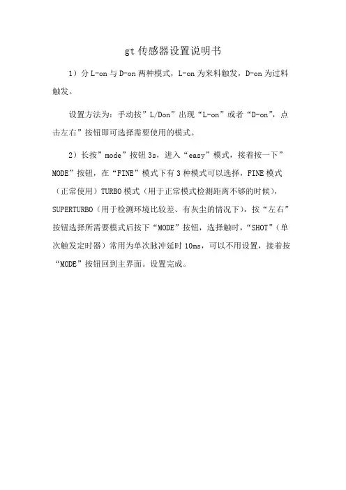
1)分L-on与D-on两种模式,L-on为来料触发,D-on为过料触发。
设置方法为:手动按”L/Don”出现“L-on”或者“D-on”,点击左右”按钮即可选择需要使用的模式。
2)长按”mode”按钮3s,进入“easy”模式,接着按一下”MODE”按钮,在“FINE”模式下有3种模式可以选择,FINE模式(正常使用)TURBO模式(用于正常模式检测距离不够的时候),SUPERTURBO(用于检测环境比较差、有灰尘的情况下),按“左右”按钮选择所需要模式后按下“MODE”按钮,选择触时,“SHOT”(单次触发定时器)常用为单次脉冲延时10ms,可以不用设置,接着按“MODE”按钮回到主界面。
设置完成。

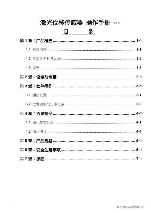
激光位移传感器操作手册V2.0目录第1章:产品概要......................................................................... 1-11.1 包装内容 ......................................................................................... 1-11.2 各部件名称及功能........................................................................... 1-21.3 安装................................................................................................. 1-3 第2章:设定与测量 ..................................................................... 2-1 第3章:软件操作......................................................................... 3-13.1 通信设置 ......................................................................................... 3-13.2 位置读取与归零设定 ....................................................................... 3-2 第4章:通讯指令......................................................................... 4-14.1 通讯参数列表 .................................................................................. 4-14.2 通讯协议 ......................................................................................... 4-4 第5章:产品规格......................................................................... 5-1 第6章:安全注意事项.................................................................. 6-1 第7章:保固 ................................................................................ 7-1版本更新历程激光位移计操作手册V2.0版本更新历程版本更新日期V1.0 第一版发行2018/09/03V2.0 新增「反应速度设定」与「中值滤波器设定」功能说明与通讯地址设定方式。

GUD1200矿用本安型位移传感器产品使用说明书2013年1月5日目录1. 概述 (3)1.1 主要用途及使用范围 (3)1.2 型号组成及代表意义 (3)1.3 使用环境条件 (3)2 结构特征与工作原理 (3)2.1 结构 (4)2.2 工作原理 (4)3 技术特性 (4)3.1 产品执行标准 (4)3.2 主要性能 (4)3.3 主要参数 (4)3.4尺寸重量 (4)3.4.1 尺寸 (4)3.4.2 重量 (4)4 安装、调试 (4)4.1 安装条件、技术要求 (4)5 使用、操作 (5)6 故障分析与排除 (5)7 注意事项 (5)8 运输、贮存 (6)9 开箱及检查 (6)10 订货 (6)使用本产品前,请详细阅读本说明书。
GUD1200矿用本安型位移传感器1.概述1.1主要用途及使用范围矿用本安型位移传感器主要用于煤矿采煤工作面液压支架位移量的测量,其工作简单可靠,能够直观显示位置信号,避免常规的电器产品中电气电路经常出现问题的弊端。
传感器内部为干簧管及电阻,属简单设备。
传感器防爆型式为矿用本安型,防爆标志:“Exib I”。
1.2型号组成及代表意义1.3使用环境条件——环境温度-5℃~40℃;——海拔高度不超过2000m;——空气相对湿度不大于95%(25℃时);——在有瓦斯、煤尘爆炸危险的场所;——在无破坏绝缘的腐蚀性气体或蒸汽的场所;——在无显著振动和冲击的场所;——污染等级为3级;——安装类别为Ⅲ类。
2结构特征与工作原理2.1结构图1 结构图2.2工作原理指示环固定在液压支架上,当液压支架位移发生变化时带动指示环前后动作,指示环上封装有磁铁,在传感器杆体每0.05m处分别装有干黄管,当磁铁接近干簧管时,导致干簧管接通。
3技术特性3.1产品执行标准本产品执行标准GB3836-2010、Q/0104ZMD047—2013。
3.2主要性能--输入电压:DC12V;3.3主要参数3.3.1 电压:DC12V;3.3.2 接点容量:12V/1A。
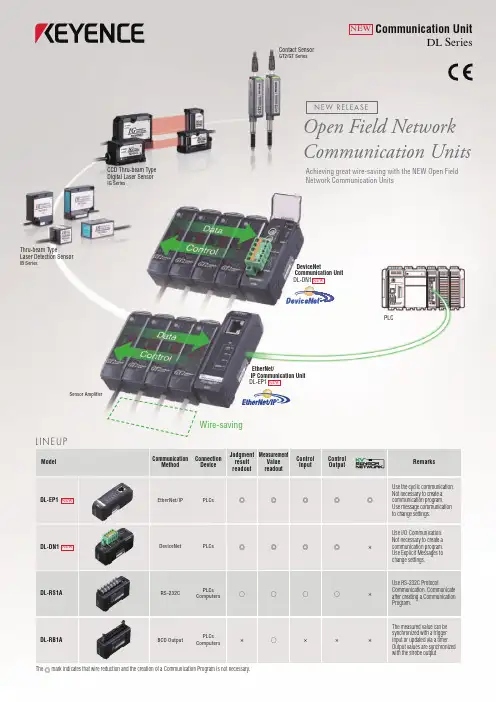
ModelCommunication Method ConnectionDeviceJudgment resultreadoutMeasurementValue readout ControlInputControl OutputRemarksDL-RS1A RS-232CPLCs Computers○○○○×Use RS-232C ProtocolCommunication. Communicate after creating a Communication Program.DL-RB1A BCD OutputPLCs Computers×○×××The measured value can be synchronized with a trigger input or updated via a timer. Output values are synchronized with the strobe output.The ◎ mark indicates that wire reduction and the creation of a Communication Program is not necessary.Wire-savingSensor AmplifierCCD Thru-beam Type Digital Laser SensorIG SeriesContact SensorGT2/GT SeriesPLCDL-DN1DeviceNet PLCs ◎◎◎◎×Use I/O Communication. Not necessary to create a communication program. Use Explicit Messages to change settings.NEWEtherNet/IP Communication Unit DL-EP1NEWDL-EP1EtherNet/IP PLCs ◎◎◎◎◎Use the cyclic communication. Not necessary to create a communication program. Use message communication to change settings.NEWNEWCommunication UnitDL SeriesOpen Field Network Communication UnitsAchieving great wire-saving with the NEW Open Field Network Communication UnitsThru-beam TypeLaser Detection SensorIB SeriesL I N E U PDeviceNetCommunication Unit DL-DN1NEWN E W R E L E A S EWW1-1031www.keyence .comPlease visit:SINGAPOREPhone: +65-6392-1011 Fax: +65-6392-5055SLOVAKIAPhone: +421 2 5939 6461 Fax: +421 2 5939 6200MEXICOPhone: +52-81-8220-7900 Fax: +52-81-8220-9097NETHERLANDSPhone: +31 40 20 66 100 Fax: +31 40 20 66 112POLANDPhone: +48 71 36861 60 Fax: +48 71 36861 62MALAYSIAPhone: +60-3-2092-2211 Fax: +60-3-2092-2131CZECH REPUBLICPhone: +420 222 191 483 Fax: +420 222 191 505AUSTRIAPhone: +43 22 36-3782 66-0 Fax: +43 22 36-3782 66-30BELGIUMPhone: +32 1 528 1222 Fax: +32 1 520 1623CHINAPhone: +86-21-68757500 Fax: +86-21-68757550CANADAPhone: +1-905-696-9970 Fax: +1-905-696-8340FRANCEPhone: +33 1 56 37 78 00 Fax: +33 1 56 37 78 01KOREAPhone: +82-31-642-1270 Fax: +82-31-642-1271GERMANYPhone: +49 61 02 36 89-0 Fax: +49 61 02 36 89-100HUNGARYPhone: +36 1 802 73 60 Fax: +36 1 802 73 61HONG KONGPhone: +852-3104-1010 Fax: +852-3104-1080ITALYPhone: +39-02-6688220 Fax: +39-02-66825099JAPANPhone: +81-6-6379-2211 Fax: +81-6-6379-2131SWITZERLANDPhone: +41 43-45577 30 Fax: +41 43-45577 40THAILANDPhone: +66-2-369-2777 Fax: +66-2-369-2775TAIWANPhone: +886-2-2718-8700 Fax: +886-2-2718-8711UK & IRELANDPhone: +44-1908-696900 Fax: +44-1908-696777USAPhone: +1-201-930-0100 Fax: +1-201-930-0099KEYENCE GLOBAL HEADQUARTERS1-3-14, Higashi-Nakajima, Higashi-Yodogawa-ku, Osaka, 533-8555, Japan Phone: +81-6-6379-2211Copyright (c) 2011 KEYENCE CORPORA TION. All rights reserved.DL-WW-L-E 1031-1 600956 Printed in JapanThe information in this publication is based on KEYENCE’s internal research/evaluation at the time of release and is subject to change without notice.*6956*Unit : mmSupported Sensor Amplifiers (as of March 1st, 2011)GT2 Series/GT-70A Series/IG Series*1/ IB Series*2/ IL Series*3*1 DL-RS1A units purchased on or before July 14th, 2009 cannot be used. *2 DL-DN1 units purchased on or before July 14th, 2010 cannot be used. *3 DL-EP1/DL-DN1 is not supported. Inquire separately concerning compatibility conditionsDL-DN1DL-RS1A DL-RB1ADL-EP1D I ME N S I O N S。
【松下】完整手册位移传感器选型指南位移传感器在现代工业控制领域扮演着至关重要的角色,它们精准地监测和测量设备运动中的微小变化,确保生产流程的稳定性和高效率。
松下作为传感器技术的领军品牌,提供了一系列高性能的位移传感器,以满足不同应用场景的需求。
本指南旨在帮助您了解松下位移传感器的各项特性,以便做出合适的选择。
位移传感器基础概念1. 磁电式位移传感器:通过检测磁场变化来确定位移量,适用于高精度测量环境。
2. 电位计式位移传感器:利用电阻变化与位移量成正比的原理,实现位移测量。
3. 光电式位移传感器:利用光电效应,通过测量光强度变化来检测位移。
选型要素1. 测量范围短行程(mm级):适用于小范围、高精度位移测量。
2. 精度和分辨率精度:指传感器测量结果的准确性。
分辨率:指传感器能检测到的最小位移变化。
3. 环境适应性温度:考虑传感器在特定温度范围内的稳定性和可靠性。
湿度:对于高湿环境,需选择具有相应防护等级的传感器。
抗干扰性:在电磁干扰较强的环境中,选择具有良好抗干扰性能的传感器。
4. 连接方式电气接口:根据控制系统选择合适的电气接口,如模拟输出、数字输出等。
机械接口:确保传感器与设备安装接口相匹配。
松下位移传感器系列概览1. MX系列特点:高精度,磁电式,适合各种工业应用。
应用:自动化设备、机床、半导体制造。
2. E6系列特点:高分辨率,电位计式,安装简便。
应用:精密仪器、汽车制造。
3. EX系列特点:长行程,光电式,适应性强。
应用:大型机械、物流设备。
结束语选择合适的位移传感器对于保障设备正常运行和生产效率至关重要。
希望本指南能够为您提供有价值的信息,帮助您在松下位移传感器中找到最适合您需求的型号。
如需更详细的选型建议和技术支持,请随时联系松下专业服务团队。
实际应用考量1. 耐用性使用寿命:根据传感器的工作环境和频率,选择耐用性强的产品,以确保长期稳定运行。
防护等级:对于暴露在尘埃、油污、水溅等环境中的传感器,应选择适当的防护等级(如IP65或更高)。
〖由于继续研究和生产的发展,深索公司保留在没有通知的情况下做修改的权力〗
〖由于继续研究和生产的发展,深索公司保留在没有通知的情况下做修改的权力〗
〖由于继续研究和生产的发展,深索公司保留在没有通知的情况下做修改的权力〗
〖由于继续研究和生产的发展,深索公司保留在没有通知的情况下做修改的权力〗
〖由于继续研究和生产的发展,深索公司保留在没有通知的情况下做修改的权力〗
〖由于继续研究和生产的发展,深索公司保留在没有通知的情况下做修改的权力〗
〖由于继续研究和生产的发展,深索公司保留在没有通知的情况下做修改的权力〗。
一文读懂位移传感器人们以经典电磁学为理论基础,把不便于定量检测和处理的位移、位置、液位、尺寸、流量、速度、振动等物理量转换为易于定量检测、便于作信息传输与处理的电学量。
这就是在生产生活中被广泛应用的位移传感器。
位移传感器位移传感器又称为线性传感器,是一种属于金属感应的线性器件,传感器的作用是把各种被测物理量转换为电量。
位移是和物体的位置在运动过程中移动有关的量,位移的测量方式所涉及的范围是相当广泛的。
小位移通常用应变式、电感式、差动变压器式、涡流式、霍尔传感器来检测,大的位移常用感应同步器、光栅、容栅、磁栅等传感技术来测量。
其中光栅传感器因具有易实现数字化、精度高(目前分辨率最高的可达到纳米级)、抗干扰能力强、没有人为读数误差、安装方便、使用可靠等优点,在机床加工、检测仪表等行业中得到日益广泛的应用。
位移传感器的分类及原理按工作原理分:电位器式位移传感器它通过电位器元件将机械位移转换成与之成线性或任意函数关系的电阻或电压输出。
普通直线电位器和圆形电位器都可分别用作直线位移和角位移传感器。
但是,为实现测量位移目的而设计的电位器,要求在位移变化和电阻变化之间有一个确定关系。
电位器式位移传感器的可动电刷与被测物体相连。
物体的位移引起电位器移动端的电阻变化。
阻值的变化量反映了位移的量值,阻值的增加还是减小则表明了位移的方向。
通常在电位器上通以电源电压,以把电阻变化转换为电压输出。
线绕式电位器由于其电刷移动时电阻以匝电阻为阶梯而变化,其输出特性亦呈阶梯形。
如果这种位移传感器在伺服系统中用作位移反馈元件,则过大的阶跃电压会引起系统振荡。
因此在电位器的制作中应尽量减小每匝的电阻值。
电位器式传感器的另一个主要缺点是易磨损。
它的优点是:结构简单,输出信号大,使用方便,价格低廉。
磁致伸缩位移传感器磁致伸缩位移传感器,通过内部非接触式的测控技术精确地检测活动磁环的绝对位置来测量被检测产品的实际位移值的。
是利用磁致伸缩原理、通过两个不同磁场相交产生一个应变脉冲信号来准确地测量位置的。
gt2-71n中文使用说明书
基恩士AUTOIDNAVIGATOR怎么使用
KEYENCE基恩士GT-H10位移传感器,配GT-71(GT-71A为NPN型)光纤放大器其输出工作原理图如下:输出开关量点PLC可以通过I/O 输入点接收,如果PLC需要采集其精确定位数据信号,则还需要配
DL-RS1A通讯模块,此模块与PLC之间用RS...
基恩士激光位移传感器怎样输出数据
——有0~20mA,0~5V模拟信号输出,配合通用的数采转换成数
字信号就可以了.
基恩士激光位移传感器LK - G5000与LK - G5001有什么区别除了精度外没有区别,LK-G5000是日本国内应用的,Lk-G5001是针对海外销售的.
位移传感器的作用是什么?都有哪些型号?
位移传感器又称为线性传感器,是一种属于金属感应的线性器件,传感器的作用是把各种被测物理量转换为电量.在生产过程中,位移
的测量一般分为测量实物尺寸和机械...
有激光类型的微米位移传感器吗? -
有的传感器(英文名称:transducer/sensor)是一种检测装置,
能感受到被测量的信息,并能将感受到的信息,按一定规律变换成为
电信号或其他所需形式的信息输出,以满足信息的传输、处理、存储、显示、记录和控制等要求.传感器的特点包括:微型化、数字化、智能化、多功能化、系统化、网络化.它是实现自动检测和自动控制的首
要环节.传感器的存在和发展,让物体有了触觉、味觉和嗅觉等感官,让物体慢慢变得活了起来.通常根据其基本感知功能分为热敏元件、光敏元件、气敏元件、力敏元件、磁敏元件、湿敏元件、声敏元件、放射线敏感元件、色敏元件和味敏元件等十大类.。
固高科技(深圳)有限公司 地 址:深圳市高新技术产业园南区深港产学研基地西座二层W211室 电 话:0755-******** 26970819 26970824 传 真:0755-******** 电子邮件:support@ 网 址: 固高科技(香港)有限公司地 址:香港九龙清水湾香港科技大学新翼楼3639室电 话:(852) 2358-1033传 真:(852) 2358-4931电子邮件:info@网 址:/GT 系列运动控制器用户手册务必将此手册交给用户z 非常感谢您选购GT 系列运动控制器z 在您使用之前,请仔细阅读此手册,确保正确使用。
z 请将此手册妥善保存,以备随时查阅。
版权声明目录第一章概述------------------------------------------------------------------------------------------------------------------1-11.1简介..........................................................................................................................................................1-11.2 GT系列运动控制器型号及含义...........................................................................................................1-11.3 GT系列控制器功能列表.......................................................................................................................1-21.4 电机控制系统的基本组成.....................................................................................................................1-3第二章快速使用 ------------------------------------------------------------------------------------------------------------2-12.1 开箱检查...............................................................................................................................................2-12.2 GT系列运动控制卡的外形结构........................................................................................................2-12.3 安装步骤.................................................................................................................................................2-22.3.1 步骤1:在运动控制卡上设置跳线(仅对ISA卡).............................................................2-22.3.2 步骤2:将运动控制卡插入计算机.........................................................................................2-52.3.3 步骤3:安装控制器通讯驱动(Windows操作系统).........................................................2-52.3.4 步骤4:建立主机与运动控制器的通讯(Windows操作系统).........................................2-62.3.5 步骤5:连接电机和驱动器.....................................................................................................2-62.3.6 步骤6:连接控制卡和端子板.................................................................................................2-72.3.7 步骤7:连接驱动器、系统输入/输出和端子板....................................................................2-7第三章系统调试------------------------------------------------------------------------------------------------------------3-13.1 系统初始化.............................................................................................................................................3-13.2 设置控制输出,驱动使能(轴开启).................................................................................................3-33.3 PID参数调节.......................................................................................................................................3-43.4 以梯形曲线运动模式实现单轴运动.....................................................................................................3-4附录A 技术参数-----------------------------------------------------------------------------------------------------------A-1附录B 位置、速度、加速度设置---------------------------------------------------------------------------------------B-1B.1 位置设置...............................................................................................................................................B-1B.2 速度设置...............................................................................................................................................B-1B.3 加速度设置...........................................................................................................................................B-2附录C 典型接线-----------------------------------------------------------------------------------------------------------C-1C.1 控制器与Panasonic驱动器速度控制方式接线.................................................................................C-1C.2 控制器与Panasonic驱动器位置控制方式接线.................................................................................C-2C.3 控制器与SANYO DENKI PV1系列驱动器速度控制方式接线......................................................C-3C.4 控制器与SANYO DENKI PV1系列驱动器位置控制方式接线......................................................C-4C.5 控制器与SANYO DENKI PY0/PY2系列驱动器速度控制方式接线........................................................C-5C.6 控制器与SANYO DENKI PY0/PY2系列驱动器位置控制方式接线........................................................C-6C.7 控制器与SANYO DENKI PU系列驱动器速度控制方式接线.................................................................C-7C.8 控制器与Y ASKA W A SER VOP ACK系列驱动器速度/力矩控制方式接线...............................................................C-8C.9 控制器与Y ASKA W A SER VOP ACK系列驱动器位置控制方式接线........................................................C-9C.10 控制器与YASKAWA SGDE系列驱动器位置控制方式接线.......................................................C-10C.11 控制器与YASKAWA SGDM系列驱动器速度控制方式接线.......................................................C-11C.12 控制器与YASKAWA SGDM系列驱动器位置控制方式接线......................................................C-12C.13 控制器与三菱MEL SERVO-J2-SUPER系列驱动器速度控制方式接线.....................................C-13C.14 控制器与三菱MEL SERVO-J2-SUPER系列驱动器位置控制方式接线.....................................C-14C.15 控制器与FALDIC-W系列驱动器速度控制方式接线..................................................................C-15C.16 控制器与FALDIC-W系列驱动器位置控制方式接线..................................................................C-16 附录D 故障处理-----------------------------------------------------------------------------------------------------------D-1附录E GT Commander使用说明----------------------------------------------------------------------------------------E-1E.1 GTCommander窗口介绍及基本操作..................................................................................................E-1E.1.1 菜单和工具栏............................................................................................................................E-9E.1.2 系统状态显示............................................................................................................................E-9E.1.3 基于轴的控制............................................................................................................................E-9E.1.4 基于坐标系的控制....................................................................................................................E-9E.1.5 输入输出控制..........................................................................................................................E-10E.1.6 GT命令编辑和运行.................................................................................................................E-10E.1.7 基本参数设置窗口..................................................................................................................E-10E.1.8 选项设置窗口..........................................................................................................................E-10E.1.9 状态栏......................................................................................................................................E-10E.1.10 XY(Z)平台控制窗口..............................................................................................................E-10E.1.11 XY(Z)平台基本参数设置窗口................................................................................................E-11E.2 操作示例..............................................................................................................................................E-11E.3 异常情况解决.....................................................................................................................................E-13E.4 初始化文件GTCmd.ini和XY(Z)Table.ini.......................................................................................E-13E.5 GT Commander文件列表...................................................................................................................E-141.4 电机控制系统的基本组成1.运动控制器及其端子板;2a. 对于ISA总线卡,具有ISA插槽的IBM-PC或其兼容机;——或——2b. 对于PCI总线卡,具有PCI插槽的IBM-PC或其兼容机;3.具有增量式编码器的伺服电机或步进电机;4.驱动器;5.驱动器电源;6.+12V~+24V直流电源(用于接口板电源);7.原点开关、正/负限位开关(根据系统需要可选)。
Model
Communication Method Connection
Device
Judgment result
readout
Measurement
Value readout Control
Input
Control Output
Remarks
DL-RS1A RS-232C
PLCs Computers
○○○○×
Use RS-232C Protocol
Communication. Communicate after creating a Communication Program.
DL-RB1A BCD Output
PLCs Computers
×○×××
The measured value can be synchronized with a trigger input or updated via a timer. Output values are synchronized with the strobe output.
The ◎ mark indicates that wire reduction and the creation of a Communication Program is not necessary.
Wire-saving
Sensor Amplifier
CCD Thru-beam Type Digital Laser Sensor
IG Series
Contact Sensor
GT2/GT Series
PLC
DL-DN1
DeviceNet PLCs ◎◎◎◎×
Use I/O Communication. Not necessary to create a communication program. Use Explicit Messages to change settings.
NEW
EtherNet/
IP Communication Unit DL-EP1NEW
DL-EP1
EtherNet/IP PLCs ◎◎◎◎◎
Use the cyclic communication. Not necessary to create a communication program. Use message communication to change settings.NEW
NEW
Communication Unit
DL Series
Open Field Network Communication Units
Achieving great wire-saving with the NEW Open Field Network Communication Units
Thru-beam Type
Laser Detection Sensor
IB Series
L I N E U P
DeviceNet
Communication Unit DL-DN1NEW
N E W R E L E A S E
WW1-1031
www.keyence .com
Please visit:
SINGAPORE
Phone: +65-6392-1011 Fax: +65-6392-5055SLOVAKIA
Phone: +421 2 5939 6461 Fax: +421 2 5939 6200
MEXICO
Phone: +52-81-8220-7900 Fax: +52-81-8220-9097NETHERLANDS
Phone: +31 40 20 66 100 Fax: +31 40 20 66 112POLAND
Phone: +48 71 36861 60 Fax: +48 71 36861 62MALAYSIA
Phone: +60-3-2092-2211 Fax: +60-3-2092-2131CZECH REPUBLIC
Phone: +420 222 191 483 Fax: +420 222 191 505AUSTRIA
Phone: +43 22 36-3782 66-0 Fax: +43 22 36-3782 66-30BELGIUM
Phone: +32 1 528 1222 Fax: +32 1 520 1623CHINA
Phone: +86-21-68757500 Fax: +86-21-68757550CANADA
Phone: +1-905-696-9970 Fax: +1-905-696-8340FRANCE
Phone: +33 1 56 37 78 00 Fax: +33 1 56 37 78 01
KOREA
Phone: +82-31-642-1270 Fax: +82-31-642-1271
GERMANY
Phone: +49 61 02 36 89-0 Fax: +49 61 02 36 89-100HUNGARY
Phone: +36 1 802 73 60 Fax: +36 1 802 73 61HONG KONG
Phone: +852-3104-1010 Fax: +852-3104-1080ITALY
Phone: +39-02-6688220 Fax: +39-02-66825099JAPAN
Phone: +81-6-6379-2211 Fax: +81-6-6379-2131SWITZERLAND
Phone: +41 43-45577 30 Fax: +41 43-45577 40THAILAND
Phone: +66-2-369-2777 Fax: +66-2-369-2775TAIWAN
Phone: +886-2-2718-8700 Fax: +886-2-2718-8711UK & IRELAND
Phone: +44-1908-696900 Fax: +44-1908-696777USA
Phone: +1-201-930-0100 Fax: +1-201-930-0099
KEYENCE GLOBAL HEADQUARTERS
1-3-14, Higashi-Nakajima, Higashi-Yodogawa-ku, Osaka, 533-8555, Japan Phone: +81-6-6379-2211
Copyright (c) 2011 KEYENCE CORPORA TION. All rights reserved.DL-WW-L-E 1031-1 600956 Printed in Japan
The information in this publication is based on KEYENCE’s internal research/evaluation at the time of release and is subject to change without notice.*
6
9
5
6
*
Unit : mm
Supported Sensor Amplifiers (as of March 1st, 2011)
GT2 Series/GT-70A Series/IG Series*1/ IB Series*2/ IL Series*3
*1 DL-RS1A units purchased on or before July 14th, 2009 cannot be used. *2 DL-DN1 units purchased on or before July 14th, 2010 cannot be used. *3 DL-EP1/DL-DN1 is not supported. Inquire separately concerning compatibility conditions
DL-DN1DL-RS1A DL-RB1A
DL-EP1
D I M
E N S I O N S。