以太网测试仪(ETS-1000)使用手册
- 格式:doc
- 大小:1.23 MB
- 文档页数:11

ETS-1000使用手册2011年1月28日EXFO的ETS-1000是一款经济高效的手持式以太网分析仪,服务提供商可使用该仪器进行下一代运营商以太网服务的开通和安装。
ETS-1000具有两个完全独立的测试端口,可支持以下接口:10/100/1000Base-T、1000Base-LX和1000Base-ZX。
下图为仪器外观:一、基本功能介绍:1、按F1进入“Setup”设置界面,如下图所示:A)进入网络设置界面,可以设置各端口的IP、掩码、网关及DNS。
如下图所示:B)进入接口设置界面,可以设置各端口的速率(10/100/100/Automatic)、Autoneg(自动协商On/Off)、MAC地址、VLAN及VLANID等参数。
如下图所示C)ETS-1000设置为仪器基本设置,按出厂默认设置即可。
2、按F2进入“Tools”设置界面。
此界面可以测试以太网功能。
A)PING测试:Setup可以设置要PING的IP地址。
B)路由跟踪:可以测试IP 数据报访问目标所采取的路径。
C)DNS查找:输入网址,可以查找DNSD)ARP监测:是否有ARP欺骗。
如下图:E)TCP客户端:可测试访问网页是否正常。
TCP客户端设置:F)电缆测试:可测试电缆是否正常。
G)环回:可以设置环回端口的参数(可选项为Off, 1层,2层,3层,4层环回)。
如下图所示:3、按F3进入“Tests”设置界面。
A)RFC-2544标准测试:定义了四个测试:吞吐量,延迟,帧丢失率,背靠背。
如下图所示:(背靠背性能测试通过以最大帧速率发送突发传输流并测量无包丢失时的最大突发(burst)长度(总包数量)来测试被测设备的缓冲区容量。
)进入设置界面如下图所示:Topology参数:可以设置收发端端口。
若双仪表测试,则收发端为本端;若单仪表测试,则收发端为不同端口。
如下图所示:Header参数:设置Src MAC和IP及Dst MAC和IP。

以太网测试仪使用方法以太网测试仪简介以太网测试仪,是网络管理和维护人员非常需要一款功能多、体积小、使用方便、价格合理的高性价比和手持式以太网络分析仪,以便迅速解决网络不通、网速慢、丢包、IP地址冲突、恶意攻击等网络常见故障并确保网络通畅。
采用彩色触摸屏界面,操作简单,手持式设计,机身小巧便携,双千兆测试端口,能够深入分析和发现网络出现的问题,是网络维护和管理人员的最佳帮手。
以太网测试仪主要功能数据包捕获和分析,通过用户自定义的过滤器,LE80可以任意筛选、捕获和存储数据包进行现场详细分析或下载到PC后使用随机配备的专用协议分析软件进行深入分析。
双千兆测试端口,不同于其他测试产品,LE80配备两个RJ-45千兆测试端口,两个端口可以完全独立工作,使用其中任一端口即可进行流量生成、抓包、Ping、链路测试、追踪路由、DHCP和设备查找等测试,这样,即使一个技术人员即可完成网络故障诊断的一切工作。
流量生成和带宽测试,LE80的流量生成功能可以调整数据包比例和大小,并产生高达100%流量负荷,用于评估不同网络吞吐量等级下网络的实际性能。
使用一台或两台LE80测试仪,即可完成网络可用带宽的测试,为网络性能评估和网络升级等业务提供有效的参考信息。
RFC2544测试,LE80也提供基于RFC2544,包含流量和测试性能指标的压力测试。
压力测试包含吞吐量、延迟、丢包、背靠背,这些测试既可以在同一台设备上的两个独立端口间进行,也可以使用两台位于不同网络中的两台设备之间进行。
网络带宽检测,LE80可以显示当前网络中每台设备的网络带宽占用情况以及设备的IP地址和Mac地址,可以迅速定位非正常占用带宽者,直观反映网络使用状态。
设备搜寻和查找,LE80可以自动搜寻并显示网络中接入的设备名称、IP地址、MAC地址以及各自占用的数据流量,为网络管理和故障诊断提供重要的参考信息网线测试,POE(以太网供电)测试可以测量电压和通电电流测量,以确定有源网络设备的实际功率。

以太网测试仪使用方法
以太网测试仪使用方法
以太网测试仪简介
以太网测试仪,是网络管理和维护人员非常需要一款功能多、体积小、使用方便、价格合理的高性价比和手持式以太网络分析仪,以便迅速解决网络不通、网速慢、丢包、IP地址冲突、恶意攻击等网络常见故障并确保网络通畅。
采用彩色触摸屏界面,操作简单,手持式设计,机身小巧便携,双千兆测试端口,能够深入分析和发现网络出现的问题,是网络维护和管理人员的最佳帮手。
以太网测试仪主要功能
数据包捕获和分析,通过用户自定义的过滤器,LE80可以任意筛选、捕获和存储数据包进行现场详细分析或下载到PC后使用随机配备的专用协议分析软件进行深入分析。
双千兆测试端口,不同于其他测试产品,LE80配备两个RJ-45千兆测试端口,两个端口可以完全独立工作,使用其中任一端口即可进行流量生成、抓包、Ping、链路测试、追踪路由、DHCP和设备查找等测试,这样,即使一个技术人员即可完成网络故障诊断的一切工作。
流量生成和带宽测试,LE80的流量生成功能可以调整数据包比例和大小,并产生高达100%流量负荷,用于评估不同网络吞吐量等级下网络的实际性能。
使用一台或两台LE80测试仪,即可完成网络可用带宽的测试,为网络性能评估和网络升级等业务提供有效的参考信息。
RFC2544测试,LE80
也提供基于RFC2544,包含流量和测试性能指标的压力测试。
SIGNAL TEK™Cable Performance T esterI Gigabit PerformanceQualification – Test toIEEE 802.3 standardsI Selectable PerformanceT esting – qualify performanceof Data, Voice over IP, andIP Video applicationsI Performs Gigabit Ethernetlink establishment test in10 secondsI Data Monitoring to detectintermittent network problemsI Smart Autotest Functiondetects the presence of theSIGNAL TEK remote, activenetwork device or open endedcable and automatically runsthe appropriate test suiteI Intuitive Graphical UserInterface for fast andeasy operationI Internal and USBData Storage –store 20,000 tests internallyor unlimited on USB driveI Prints Easy-to-Read Pass/Fail Qualification ReportsSIGNALTEK™– High-Performance Gigabit Ethernet TestingSIGNALTEK™is the most cost-effective Gigabit Ethernet cableAutotest key to initiate tests from the remote end for one personoperation2.8Љ(7.1cm) 1⁄4VGA Color Display with backlighting for use in low light conditionMulti-color LEDs indicate link status,loopback mode,10/100 and Gigabit device detection,Autotest pass/fail,and battery conditionEasy-to-navigate user interfaceCompact design and soft over-mold sides fit well into any sized handContext sensitive softkeysSingle button cable testingQuick navigation key returns to Job Manager screenSingle button push for active network testing and monitoring Port status function detects 10/100 or Gigabit Ethernet devicesDisplays result for last autotest via red or green LED indicationSIGNAL TEK ™Standard KitCatalog No. 33-974I1 SIGNALTEK ™Near-end and remote-end handset IDEAL INDUSTRIES, INC.03/06Printed in U.S.A.ISO 9001:2000 QMSNo. 33-974SIGNALTEK ™OptionalPower Adapter – 4010-00-0136DESCRIPTION CAT NUMBER SIGNALTEK™ Cable Performance Tester 33-974Replacement cable accessory kit –Contains all original cables in SIGNALTEK™ kit 1219-91-0003RJ45 to 8 head alligator clipK-7920OPTIONALUniversal (120-240V) AC-DC power adapter (1)4010-00-0136。
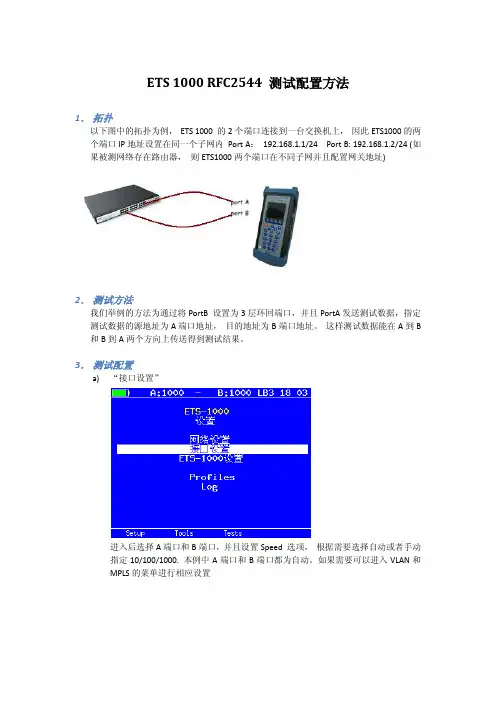
ETS 1000 RFC2544 测试配置方法1.拓扑以下图中的拓扑为例,ETS 1000 的2个端口连接到一台交换机上,因此ETS1000的两个端口IP地址设置在同一个子网内Port A:192.168.1.1/24 Port B: 192.168.1.2/24 (如果被测网络存在路由器,则ETS1000两个端口在不同子网并且配置网关地址)2.测试方法我们举例的方法为通过将PortB 设置为3层环回端口,并且PortA发送测试数据,指定测试数据的源地址为A端口地址,目的地址为B端口地址。
这样测试数据能在A到B 和B到A两个方向上传送得到测试结果。
3.测试配置a)“接口设置”进入后选择A端口和B端口,并且设置Speed 选项,根据需要选择自动或者手动指定10/100/1000. 本例中A端口和B端口都为自动。
如果需要可以进入VLAN和MPLS的菜单进行相应设置b)接口设置完成后进入“网络设置”菜单,如之前拓扑设置A 地址192.168.1.1 和B地址192.168.1.2 (如果被测网络中有路由器则地址应该在不同子网,并设置相应网关地址)c)进入“tools”菜单,设置环回端口,进入菜单选择端口B,设置Layer 为3。
此时,端口B将交换所受到数据包的源地址和目的地址,以便把测试数据发回到A 端口。
d)返回主界面进入“tests“菜单,进入RFC 2544 测试设置e)进入“设置“f)进入“topology“菜单,设置TX和RX port 都为Ag)返回上一级进入“Header“,设置Src MAC 和IP 为A,Dst MAC和IP 为Bh)返回上一级进入“Frames“并选择需要测试的帧大小i)返回上一级进入“Throughput“,设置传输的速率“Rate”,测试时间“Trial,S”RFC2544 推荐为60秒以上j)返回并进入“Latency”,设置测试时间“trial,s”并设置测试速率“Rates”为Throughput。
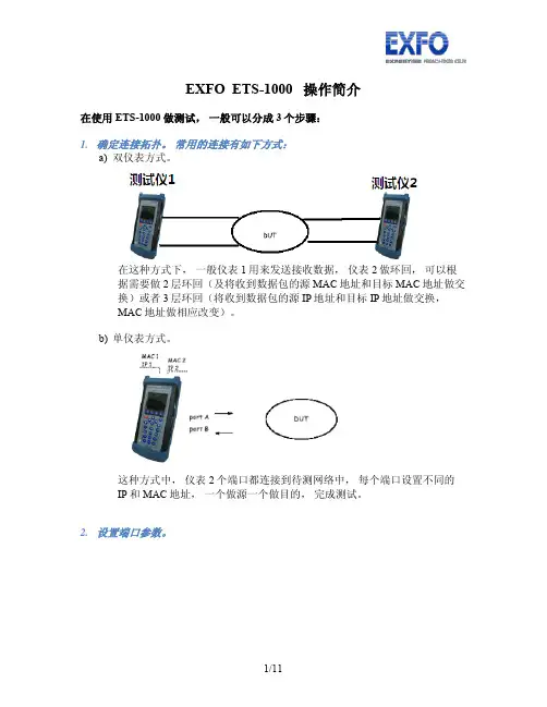
EXFO ETS-1000 操作简介在使用ETS-1000 做测试,一般可以分成3个步骤:1.确定连接拓扑。
常用的连接有如下方式:a)双仪表方式。
在这种方式下,一般仪表1用来发送接收数据,仪表2做环回,可以根据需要做2层环回(及将收到数据包的源MAC地址和目标MAC地址做交换)或者3层环回(将收到数据包的源IP地址和目标IP地址做交换,MAC地址做相应改变)。
b)单仪表方式。
这种方式中,仪表2个端口都连接到待测网络中,每个端口设置不同的IP和MAC地址,一个做源一个做目的,完成测试。
2.设置端口参数。
如图在设置界面设置网络参数和接口参数a)在网络设置中设置IP地址,子网掩码,网关地址参数b)在接口设置中设置MAC地址, 10, 100,1000M速率模式,以及是否要启用VLAN,以及VLAN ID3.设置测试类型a)RFC-2544 测试为业界衡量网络性能的主要标准,通过吞吐量,背对背,延迟和帧丢失等方面来衡量网络性能。
b)混合流量可以允许客户设置最多10条数据流,指定不同流的字节,速度等具体参数真实模拟网络流量,衡量网络性能。
i.在混合模式配置界面设置数据流的数量Stream 可选择1到10条数据流, Duration 设定数据流生成的时间ii.进入Topology 设定发送数据端口和接收数据端口,收发端口可以不同也可以相同iii.进入header 设置MAC地址和IP地址iv.进入Frame 设置每个数据流的大小v.最后在Rate 菜单中设置每个数据流的速率然后在混合流量->测试中开始测试,可以得到如下结果:c)BERT 误码率测试,允许发送特定的二进制码率,通过发送接收端的对比统计出误码的比特,比率等信息。
最后的测试实例有配置介绍。
d)数据包抖动,根据RFC4689的原理测试数据包在线路上的延迟差异,这种测试对延迟敏感的数据流如语音视频数据特别重要。
e)测试流量是用来生成流量拱数据包抖动测试使用,可以单端口发送接收或者从A端口发送的B端口两种模式。

ETS-1000使用手册2011年1月28日EXFO的ETS-1000是一款经济高效的手持式以太网分析仪,服务提供商可使用该仪器进行下一代运营商以太网服务的开通和安装。
ETS-1000具有两个完全独立的测试端口,可支持以下接口:10/100/1000Base-T、1000Base-LX和1000Base-ZX。
下图为仪器外观:一、基本功能介绍:1、按F1进入“Setup”设置界面,如下图所示:A)进入网络设置界面,可以设置各端口的IP、掩码、网关及DNS。
如下图所示:B)进入接口设置界面,可以设置各端口的速率(10/100/100/Automatic)、Autoneg(自动协商On/Off)、MAC地址、VLAN及VLANID等参数。
如下图所示C)ETS-1000设置为仪器基本设置,按出厂默认设置即可。
2、按F2进入“Tools”设置界面。
此界面可以测试以太网功能。
A)PING测试:Setup可以设置要PING的IP地址。
B)路由跟踪:可以测试IP 数据报访问目标所采取的路径。
C)DNS查找:输入网址,可以查找DNSD)ARP监测:是否有ARP欺骗。
如下图:E)TCP客户端:可测试访问网页是否正常。
TCP客户端设置:F)电缆测试:可测试电缆是否正常。
G)环回:可以设置环回端口的参数(可选项为Off, 1层,2层,3层,4层环回)。
如下图所示:3、按F3进入“Tests”设置界面。
A)RFC-2544标准测试:定义了四个测试:吞吐量,延迟,帧丢失率,背靠背。
如下图所示:(背靠背性能测试通过以最大帧速率发送突发传输流并测量无包丢失时的最大突发(burst)长度(总包数量)来测试被测设备的缓冲区容量。
)进入设置界面如下图所示:Topology参数:可以设置收发端端口。
若双仪表测试,则收发端为本端;若单仪表测试,则收发端为不同端口。
如下图所示:Header参数:设置Src MAC和IP及Dst MAC和IP。
/ARTEX-455-9100-406MHz-ELT-Test-set.aspxTo buy, sell, rent or trade-in this product please click on the link below:TABLE OF CONTENTS Introduction (1)Application (1)Features (3)ETS w/ Antenna (4)Hardware Operation (5)Meazura Operation (6)Controls (6)Palm™ Desktop Software (7)Sarcalc Desktop (7)Hot Sync (7)Maintaining your Battery Pack (9)Battery Usage (9)Battery Warnings (9)Battery Storage (9)Battery Charging (10)Recycle and Disposal Methods (11)Using the ELT Reader (12)ETS Main Screen View (13)Software Screen View (13)Waiting for Data” Screen View (14)Example of Standard Location Data View (14)Example of 24-Bit Address Data View (15)Reader Database (16)Deleting Database Screen Views (16)ELT Reader Preferences (17)Preferences Screen View (17)Printing Messages (18)ELT Test Set Unit (19)Meazura MEZ1000 Specifications: (20)ETS Module Specifications: (20)Calibration (20)System Component Part Numbers (21)Optional Equipment (21)Troubleshooting Guide (22)Technical Assistance (23)Warranty Information (23)Index (24)Page iiFeaturesAll 406 MHz aircraft protocols decodedReception of 406.025 MHz or 406.028 MHz frequenciesWaterproof to IP67 standardsRuggedized caseInternal database of received messages and programmingOptional printing of current or stored messages via IR or Serial linksDesktop application for database storage and reviewLong life rechargeable batteryBuilt-in RF attenuatorPage 3 of 24ETS w/ AntennaPage 4 of 24Hardware OperationPrior to use, install battery pack into test set. To close, place the battery pack with the top end in first. Now push down on the bottom end of the battery pack ensuring that it is firmly in place. Now push the clip firmly towards the bottom of the test set until it clicks into place. Charge the ETS battery using the supplied USB cable connection and wall charger, connect as shown below. Charge for 2 to 3 hours. Upon power-up, follow on screen directions for initialization and setting the time. The initialization routine is very important to ensure proper function of the stylus on the test set screen.Page 5 of 24Palm™ Desktop SoftwarePrior to use, the Palm™ Desktop Software as supplied on the CD-ROM disc (Artex P/N 510-1200) supplied must be installed on your Windows95/NT/98/2000/Me/XP PC that will be used to interface with the ETS. Follow the on-screen instructions for installation.Note: The Palm desktop software works most amiably if a single Meazura (Palm) device is associated with a single computer. It is possible to use more than one Meazura (or Palm) device with the same computer but attention must be given to the selection of appropriate user names when transferring data to and from different units. The Palm software identifies the User Name when the Palm Desktop application is installed on a PC. Only one User Name can be used with the Artex applications.Sarcalc DesktopThe Sarcalc Desktop application SarCalc Desktop V1.2 (or higher) may also be installed on a PC (available free for download at ). Once installed, the entire Sarcalc or Artex database can be reviewed. Note: The Meazura unit must be HotSync'd with the Palm Desktop software to load the database from the Meazura unit to the PC. Once sync'd, the database can be opened on the PC by starting the SarCalcDesk.exe application and opening the database from the file menu. The Palm HotSync will usually store the database file inC:\ProgramFiles\Palm\Artex\Backup\ (where Artex is the Meazura user name. Be sure to use the “Artex” user name whenever performing a “HotSync”. All Artex provided software is loaded to the Meazura using this user name.) The database will be named SarcalcDB.PDB. If the Meazura was set-up on the PC with a different User Name than “Artex”, check the folder for that User Name to locate the Backup file to find the Sarcalc and Artex database information.Hot SyncOnce installed and configured, the Palm™ Desktop Software will allow installation of additional software applications as well as performing the hot sync function to transfer data to and from the ETS (Meazura unit). Artex provides a USB cable (452-0103) to connect to a PC. The hot sync function is accessed by tapping thePage 7 of 24Maintaining your Battery PackBattery UsageThe Meazura™ MEZ1000 RDA comes with a custom rechargeable Lithium Ion battery pack that can only be purchased from Aceeca or Artex. The battery pack allows about 60 hours of continual use.Battery Warnings•D o not heat or throw the battery into a fire.•D o not use or store the battery close to fire or inside a car in which the temperature may be over 60°C.•D o not put the battery in your pocket or in a bag together with metal objects such as necklaces, hairpins, coins, or screws. Do not store the battery with such objects.•D o not short circuit the (+) and (-) terminals with a metal object such as a needle, necklace or hairpin.•D o not pierce the battery with a sharp object such as a nail.•D o not hit with a hammer, step on, throw, drop or allow the battery to undergo other such strong shock.•D o not disassemble or modify the battery.•D o not solder the battery directly.•D o not use a battery that is severely scarred or deformed.Battery StorageUnlike NiCad (Nickel Cadmium) batteries or NiMH (Nickel-metal Hydride) batteries, lithium-ion batteries should be charged early and often. Never use battery maintenance software to maintain your battery as this can reduce the life of your battery. Li-ion batteries should be kept cool. They should not be subjected to freezing temperatures. Aging will occur much faster at high temperatures (such as a hot car) and will reduce the life of your battery. Purchase a Li-Ion battery pack only when you need a replacement, ensuring you receive a fresh battery pack.•S top using the battery if it exhibits abnormal heat, odor, color, deformation or is in an abnormal condition.•K eep away from fire immediately when leakage or foul odor is detected.•I f liquid leaks onto your skin or clothes, wash well with fresh water immediately.•I f liquid leaking from the battery gets into your eyes, do not rub your eyes.Wash them well with clean water and consult a doctor immediately.•B efore using the battery, be sure to read the user's manual and cautions onPage 9 of 24Recycle and Disposal MethodsLithium ion batteries, like all rechargeable batteries are recyclable and should be recycled.CAUTIONIf your battery is damaged, or if it no longer holds a charge, dispose of it promptly and properly. Do not dispose of it along with general waste. Call your local waste disposal agency or environmental agency for advice on disposing of the battery.Page 11 of 24Waiting for Data” Screen ViewOnce a valid message is received, all encoded data is displayed on the screen as shown below. The first line contains the 15 digit Hex ELT ID. This ID is used to register the ELT with the national authorities (NOAA in USA). The second line indicates the message type: Test or Normal, and Short or Long. The third line displays the country of registry code and the country. The fourth line will contain the ELT identifying data. The ELT identifying data will consist of one of the following: serial number, aircraft 24 bit ICAO address, aircraft registration number. ELT type will be displayed (ELT) and also any auxiliary locating device (121.5 MHz ELT). If the ELT includes a navigation function, the position will be displayed in latitude/longitude. Note: The received 406 MHz frequency is not displayed. The message will be time stamped.Example of Standard Location Data ViewNote: A displayed message will remain on-screen until the “Clear” button is selected. Select “Done” to save message and proceed. A new message will not over-write the old message.Page 14 of 24If the ELT is encoded with the 24 bit ICAO address and country of registry is USA, then the ICAO address will also be decoded to an 'N' number registration as shown below.The message will be automatically saved to a database for later review. Press “clear” or right arrow key to clear screen for next message.Example of 24-Bit Address Data ViewPage 15 of 24Reader DatabaseAll recorded messages are automatically saved to a database (up to 1000 records). Select “Review” from the initial Sarcalc screen. The latest message will be displayed with the date and time the message was recorded. Navigate between older and newer saved messages by selecting “Prev” or “Next”. Any displayed message can also be printed (if optional printer software is installed). The number of records kept can be changed by selecting “Prefs” from the initial Sarcalc screen (see “Preferences”). The database can be erased by deleting the database “SarcalcDB” from the main Meazura screen as shown below. Tap the upper left-hand corner of the main screen to show the “App” pull-down screen, select “Delete” and then select “SarcalcDB” to delete. Individual records cannot be erased.Deleting Database Screen ViewsPage 16 of 24ELT Reader PreferencesIf “Prefs” is selected from the initial Sarcalc screen (see below), the following items may be selected:Readings to keep – 10, 20, 100, 1000Maximum number of readings to store in the database ICAO Format – Octal, Hex, DecimalFormat of ICAO Address displayDisplay Full Address – checked, uncheckedCheck for display of full ELT message, bits 9 –144 (30Hex digits) or leave unchecked to display only bits 26-85(15 Hex digits)Preferences Screen ViewPage 17 of 24ELT Test Set UnitThe base unit is an Aceeca Meazura MEZ1000 manufactured by Aceeca Ltd of Christchurch, NZ. The Meazura unit is ruggedized and waterproof to IP67 standards, is based on the Palm OS version 4.1.2, and features a long life battery. The ELT Test Set module plugs into the internal Aceeca MZIO slot and is secured with 2 screws – DO NOT REMOVE – DOING SO WILL VOID THE ARTEX WARRANTY.Additional operating information can be found in the Aceeca documentsMEZ1000 Quick Reference User Guide and MEZ1000 HotSync Configuration Guide located on the CD-ROM disc provided as Artex P/N 510-1200.Page 19 of 24System Component Part NumbersThe Artex ELT Test Set is being offered as a complete kit (455-9100) with the following parts:1 ea. 453-1000 ELT Test Set (ETS) Main Assembly1 ea. 110-418 Antenna, ¼ Wave Flexible Whip 418 MHz1 ea. 452-0100 Holster, Padded ELT Test Set1 ea. 452-0101 Stylus, ELT Test Set1 ea. 452-0102 Battery, ELT Test Set1 ea. 452-0103 USB Cable, ELT Test Set1 ea. 452-0104 Charger, ELT Test Set1 ea. 510-1200 Desktop Software for ELT Test Set (CD-ROM)1 ea. 570-1000 Manual, ELT Test Set OperationAny of the above part numbers may be ordered as a replacement or as a separate line item. Contact the Artex Sales department at 1-800-547-8901 for details.Optional EquipmentIf national or local regulations require that the ELT be attenuated and/or directly connected to the ETS, the following parts may be used:500-3000 Attenuator, 30 dB500-3200 Attenuator, 20 dB611-9010 Cable, Coax 6 ft.TPS to BNC (For Dual Output ELT)611-6013 Cable, Coax BNC to BNC (For Single Ouput ELT) Commercial equivalents of any of these parts may also be used.Page 21 of 24Index—A—Aceeca, 6, 20 Application, 1—B—Battery life, 20 Battery Pack, 9—C—Calibration, 20 Controls, 6—D—Database, Reader, 16—F—Features, 3—H—Hardware, 5Hot Sync, 7—I—Introduction, 1—M—Meazura, 1, 6—O—Optional Equipment, 21—P—Palm Desktop, 7Part Numbers, 21Preferences, Reader, 17Printing Messages, 18—R—Reset, hard, 22Reset, soft, 22—S—Sarcalc Desktop, 7Sarcalc software, 12Specifications, 20—T—Table of Contents, iiTechnical Assistance, 23Troubleshooting, 22—U—User name, 7Using Reader, 12—W—Warranty, 23Page 24 of 24。
以太网测试仪使用方法以太网测试仪(Ethernet tester)是一种专门用于测试以太网网络连接的仪器设备。
它可以帮助用户检测网络连接的质量、稳定性和速度,并提供有关网络故障的诊断信息。
下面将介绍如何正确使用以太网测试仪。
步骤一:设置测试仪1.将以太网测试仪的电源线插入电源插座,并确保仪器已开启。
2.连接测试仪的网线接口与要测试的以太网设备(如交换机、路由器或电脑)之间。
步骤二:选择测试模式1.在以太网测试仪上选择相应的测试模式。
常见的测试模式有连接测试、链路测试和速度测试等。
2. 根据需要选择测试的参数,如全双工或半双工、速率(10/100/1000 Mbps)等。
步骤三:进行测试1.进行连接测试:连接测试主要用于判断网络线缆的连通性。
在测试仪上选择连接测试模式,然后按下开始按钮。
测试仪会发送测试信号,如果连接是正常的,测试仪会显示连接成功。
2.进行链路测试:链路测试用于判断网络链路的质量和稳定性。
在测试仪上选择链路测试模式,然后按下开始按钮。
测试仪会发送测试信号,并检测链路中的错误、延迟和丢包等情况。
测试结束后,测试仪会显示详细的测试结果。
3.进行速度测试:速度测试用于测试网络传输速度。
在测试仪上选择速度测试模式,然后按下开始按钮。
测试仪会模拟网络传输,测量实际传输速度并显示在仪器屏幕上。
步骤四:分析测试结果1.根据测试仪显示的结果,分析网络连接的质量、稳定性和速度,判断是否存在问题。
2.如果测试结果显示错误、延迟或丢包等问题,可以尝试重新测试或检查网络设备和线缆是否连接正常。
3.如果测试结果显示传输速度低于预期,可能是网络带宽受限或其他因素导致。
可以进一步分析网络拓扑和设备配置,确定问题所在并进行解决。
步骤五:记录和报告1.记录测试仪显示的测试结果,包括测试日期、测试模式、参数设置和测试数据等。
2.如果需要,可以将测试结果生成报告,并保存供以后参考和分析。
总结:使用以太网测试仪可以帮助用户准确地测试和诊断以太网网络连接的问题。
以太网测试仪说明书
一、仪表按键说明
MENU 开关键
SET 设置、确认键
START 开始测试键
方向键
二、开机
长按MENU键开机,进入主界面。
三、以太网流量测试
进入主界面选择以太网测试,按SET键进入设置界面。
按设置键(F2),选择接口→一般→端口→通过按F3键选择端口A或端口B;通过方向键选择MAC或IPV4,设置源MAC地址或IP地址。
注意:目的MAC和目的IP为对端环回设备或仪表的MAC和IP地址。
按F1键返回→ F2设置→选择测试自动化器→ SET →添加新的测试→ SET →选择测试模式→ START。
四、RFC2544测试
RFC2544有两种测试方式:单端测试和端到端测试。
在测试自动化器添加新设备中选择RFC2544吞吐量测试,按SET键进入设置模式,通过方向键选择测试模式、持续时长、目的地址、帧长、线路负荷、高级、门限等设置项目。
测试模式→选择单端网络测试、端到端网络测试或交换机路由器测试;目的地址→设置MAC地址或IP地址。
注意:使用ARP可以解析MAC地址;使用DNS可以解析IP地址;目的地址很重要根据实际测试端口设备。
五、设置完毕,按Start键开始测试。
六、长按Menu可以选择测试报告、保存设置、打开、大容量存储、打印屏幕、
顶端菜单、关机等模式。
Automotive Ethernet 1000Base-T1 TC9 measurement using VNA Application NoteProducts:ı R&S ®ZNB4 ı R&S ®ZN-Z51 ı R&S ®ZV-Z135 ıR&S ®ZV-Z192This application note is a systematic guide to help test engineers configure the Vector Network Analyzer in order to perform compliance test on Automotive Ethernet cables according to the Open Alliance TC9 standard.Note:Please find the most up-to-date document on our homepage https:///appnote/GFM323A p p l i c a t i o n N o t ea h m u d N a s e e f , J ör n P f e i f e r , A n d r e a D 'A q u i n o 9.2019 – G F 323_2eTable of ContentsTable of Contents1Introduction (3)2Test Setup (4)3Calibrating and Configuring the VNA for Measurement (5)3.1Characterization of the Calibration Unit (5)3.2Optional de-embedding of fixture boards (7)3.3Verification of VNA Calibration Accuracy (9)4Measurement and Results (12)4.1Measurement of Mixed-Mode S-Parameters (12)4.2Measurement of TDR based CIDM (Characteristic Impedance Differential Mode) (13)5Reference (15)6Ordering Information (16)Introduction1IntroductionThe evolution towards higher connectivity & electrification in the automotive industry is faster than ever before. More and more sensors are added to vehicles as the future of transportation moves towards higher level of automation. Reliability and quality of time critical communications between different systems are nowadays under the spotlight, and Ethernet cables have become the industry standard to support the network within the car.The Open Alliance TC9 compliance specification is regarded as a qualificationbenchmark for unshielded twisted pair (UTP) cables for Automotive Ethernet [1].This document contain electrical requirements and measurement specifications on1000BASE-T1 channel and components link segment type A (UTP). It shall be used as a standardized common scale for the evaluation of the RF properties for physical layercommunication channels to enable 1000BASE-T1 technology.The focus of this application note is to describe the method of performing compliance tests according to the TC9 specification for Ethernet cable testing. Chapter 2 describes the test setup required to perform measurements on 1000BASE-T1 coaxial cablesusing the four-port ZNB4 Vector Network Analyzer (VNA) from Rohde & Schwarz.Chapter 3 explains the procedure of calibrating the VNA and checking the VNAcalibration accuracy. Finally, in chapter 4, measurement examples from the OpenAlliance TC9 compliance specification are shown.AbbreviationsThe following abbreviations are used in this application note for Rohde & Schwarzproducts:▪The R&S®ZNB4 Vector Network Analyzer is referred to as ZNB▪The R&S®ZN-Z51 Automatic Calibration Unit is referred to as ZN-Z51▪The R&S®ZV-Z135 Calibration Kit is referred to as ZV-Z135▪Device Under Test is referred to as DUTTest Setup 2Test SetupFig. 2-1: Test setup for performing TC9 measurementFig. 2-1 shows the measurement setup required to test 1000Base-T1 AutomotiveEthernet cables. The Ethernet cables are unshielded coaxial twisted pair cables and in order to perform measurements, a PCB based measurement fixture (adapter board) is used to adapt to the connectors of the Rohde & Schwarz ZNB4 Vector NetworkAnalyzer to the test cables.To start a measurement, the test setup needs to be calibrated. A full 4-port systemerror correction would ensure calibration up to the reference planes 1. A measurement between these two planes (marked in blue in Fig. 2-1) would include an undesired RF response of the adapter boards. The compensation of this effect is optional according to the Open Alliance specification. This application note shows a method to "de-embed" the adapter boards, in order to obtain a reference plane calibrated at theEthernet cable ends (marked in red in Fig. 2-1).The VNA configuration and measurement parameters are documented in the Open Alliance TC9 specification, while a systematic guide on how to calibrate and configure the ZNB4 is described in the next chapters of this document.3Calibrating and Configuring the VNA forMeasurementThe first step of any test performed with a VNA consists in calibrating the instrument.As a measure of good practice, let the VNA and the calibration unit warm up about one hour to gain stable characterization data. To obtain the required VNA calibrationaccuracy a manual calibration is usually performed but automatic calibration units can be used with the method described in the next paragraph as well. If a manualcalibration is preferred, you can ignore paragraph 3.1.The VNA needs to be configured to the settings defined in table: 4.2-2 of the OpenAlliance TC9 test specification [1].3.1 Characterization of the Calibration UnitIn order to obtain optimal calibration accuracy with an automatic calibration unit (e.g.ZN-Z51) the generation of specific characterization data of the unit is recommended. In order to do this, the user needs perform a calibration with a manual calibration kit (e.g.ZV-Z135) first. This will ensure a full system error corrected VNA and enable precisecharacterization of the calibration unit. Use the setting from [1] table 4.2-2.Fig. 3-1shows the port connections of ZNB4 with the automatic calibration unit ZN-Z51.Fig. 3-1: Setup for a Full 4-Port automatic system error calibration of the ZNB4 using ZN-Z51Then start the characterization step by disconnecting the manual calibration kit and connecting the automatic one as shown in Fig. 3-1ıTo start the characterization step, press▪CHANNEL > Calibration > Cal Devices > Characterize Cal Unit▪Select Start Characterization as shown in Fig. 3-2Fig. 3-2: Calibration unit Characterization configurationA list of all the saved characterization datasets can be found on the left of thewindow as shown aboveıPress Test Port Assignment > AutomaticıSelect Take all OSM and ThroughıSave the characterization data file on the unit▪In this example, the name "full log 2001 11.37" was usedıAfterwards, the ZN-Z51 can be used for future calibrations as follows: ▪Use the same settings as described in the standard▪Select Channel > Cal > Start (Cal Unit)▪Select all 4 ports P1, P2, P3 and P4 as shown in Fig. 3-3▪Use the characterization data generated and saved before (in this example "full log 2001 11.37")▪Select Next and follow the instructions on the screenFig. 3-3: Configuration for calibrating all four ports of the ZNB4At this point, the instrument is calibrated up to the calibration reference plane 1 in Fig.3-4. This step needs to be done only once for a calibration unit. For every newcalibration from this point onwards, the same characterization data can be used.3.2 Optional de-embedding of fixture boardsWhen the adapter boards are connected to the ZNB, the influence of the two microstrip lines up to calibration reference plane 2 can be eliminated, to obtain a measurement of the Ethernet cable only.In order to do that, connect the adapter board to the ZNB4 as shown in Fig. 3-4▪Connect P1 and P3 to adapter board 1▪Connect P2 and P4 to adapter board 2Fig. 3-4: Different calibration planes on the adapter boardTo compensate for the influence of the fixture on the measurement result, the de-embedding functionality of the ZNB can be used. The de-embedding is done in balanced mode.▪Select Measurement > Balanced Ports > (D) 2 x Balanced▪Trace > Measurement > Sdc11▪Trace Config > Add Trace▪Trace > Measurement > Sdc22▪Offset Embed > Offset > Fixture Compensation…▪Select all four ports▪Choose Offset correction: "Direct Compensation"▪Press Measurement Type: "Open"▪Press "Take" and close the dialog once the process ended"Direct Compensation" provides a frequency-dependent transmission factor. "Auto Length and Loss" uses a global electrical length and loss, so compensation is based on a transmission line model.Depending on the fixture itself, additional measures can be taken to improve the compensation result. See the R&S® ZNB/ZNBT Vector Network Analyzer User Manual for further information on the compensation approaches of the ZNB.Fig. 3-5: Mode Conversion Sdc11 and Sdc22 with open fixture after Fixture Compensation with"Direct Compensation"The microstrip lines on the adapter boards are now compensated and Fig. 3-5 shows the conversion loss values after the process. The calibration is now shifted up tocalibration reference plane 2.3.3 Verification of VNA Calibration AccuracyAfter the calibration procedure, the ZNB4 needs to be configured to balanced porttesting mode. The ZNB4 port P1 and port P3 are configured as logical port L1 and port P2 and port P4 are configured as logical port L2.▪Click Trace > Measure > Balanced Ports▪Select the configuration as shown in Fig. 3-6▪Choose reference impedance and change common mode impedance to 200Ohm as indicated in the Open Alliance specification, then hit okFig. 3-6: Balanced port configuration for the ZNB4Now the VNA calculates the mixed-mode S-parameters from the measured single-ended S-parameters and shows them in the diagram areas.At this point, a verification step needs to be performed to check the calibration accuracy of the VNA. The verification of VNA calibration accuracy is performed with two "THRU" connectors as per Open Alliance specification.Fig. 3-7 shows the calibration accuracy verification of the ZNB4 for return loss, longitudinal conversion loss and longitudinal conversion transfer loss. All values are within the limits defined in the specification.The option ZNB4-B54 "Extended Dynamic Range" improves the dynamic range of the instrument by circa 10 dB. The VNA accuracy verification test will show 5 dB lower conversion loss in this case. The result shown in Fig. 3-7 is measured without this option.Calibrating and Configuring the VNA for Measurement Fig. 3-7: Verification of calibration accuracy of return loss, longitudinal conversion loss and longitudinal conversion transfer loss4Measurement and ResultsAs an example of measurement, the return loss and insertion loss of an Ethernet cable are taken into consideration. The measurement of CIDM (Characteristic ImpedanceDifferential Mode) is also explained in the following paragraphs. The fixtures used inthe following example meet the requirements of [1].4.1 Measurement of Mixed-Mode S-ParametersIf all the steps in the previous chapters have been correctly performed, the setup isfully calibrated and configured to measure as described in Open Alliancespecifications.First, connect the Cable Under Test (CUT) as shown in Fig. 2-1.Fig. 4-1: Return loss measurement of 1000BASE-T1 according to TC9 specIn order to measure return loss or insertion loss,▪Select the corresponding S-parameter from Trace > Measurement> S-parameterFig. 4-2: Insertion loss measurement of a 1000BASE-T1 Automotive Ethernet cableFig. 4-1 and Fig. 4-2 show the return loss and insertion loss measurement of a1000BASE-T1 Automotive Ethernet cable using the ZNB4.4.2 Measurement of TDR based CIDM (CharacteristicImpedance Differential Mode)To carry out impedance measurements, the recommended VNA configurationaccording to [1] is different than the one used for the S-parameter measurements. One reason is that a linear frequency sweep is needed for converting the measurementresult from frequency domain into time domain with the Inverse Fourier Transform,while for the S-parameter measurement described above, a logarithmic sweep is used.Additionally, a higher stop frequency is advantageous for a higher resolution (shorter rise time) in the TDR.A second measurement channel can be calibrated and used to see TDR results on theVNA screen in parallel to the S-parameters. The second channel (Ch2) can beconfigured with different settings.To do thisıSelect Channel > Channel Config > Add Ch+Tr+Diag▪Ch2 is now indicated in the lower left corner of the diagram area▪Configure the VNA according to the specification of [1]▪Perform calibration (if an automatic cal unit is used, use "factory" from the characterization pool)The two channels will run sequentially.While using the active trace in Ch2 set up an impedance trace in time domain to perform the CIDM measurement by▪Meas > Z Sdd11, choose Sdd11 from the drop down menu▪Trace > Trace Config > Time Domain and check box "Time Domain"▪Choose Type "low pass step" from the drop down menu▪Press "Low Pass Settings…" and check box DC Value "Continuous extrapolation"▪Stimulus > Stop to adapt the stop time to the DUT. Electrically long DUTs need a longer analysis timeFig. 4-3: Typical CIDM measurement based on time domain measurement of an automotiveEthernet cableIn Fig. 4-3, a typical result of the impedance measurement of an automotive Ethernet cable is shown. The differential reference impedance of 100 Ω is seen up to0 ns. Then a segment with around 99 Ω corresponds to the left fixture. The cable impedance of around 96.5 Ω can be seen in the section between 2.5 ns to 3 ns followed by the right fixture with an impedance of about 100Ω.Reference5Reference[1] Link Segment Type A (UTP) 1000BASE-T1 Ethernet Channel and ComponentsSpecification - TC9, Open Alliance, Weblink: /tech-committees/tc9/Ordering Information 6Ordering InformationRohde & Schwarz The Rohde & Schwarz electronics group offersinnovative solutions in the following business fields: test and measurement, broadcast and media, secure communications, cybersecurity, radiomonitoring and radiolocation. Founded more than 80 years ago, this independent company has an extensive sales and service network and is present in more than 70 countries.The electronics group is among the world market leaders in its established business fields. Thecompany is headquartered in Munich, Germany. It also has regional headquarters in Singapore and Columbia, Maryland, USA, to manage its operations in these regions.Regional contactEurope, Africa, Middle East +49 89 4129 12345*********************************North America1888TESTRSA(188****8772)**********************************.comLatin America +1 410 910 79 88************************************Asia Pacific+65 65 13 04 88************************************** China+86 800 810 82 28 |+86 400 650 58 96***************************************Sustainable product designı Environmental compatibility and eco-footprint ı Energy efficiency and low emissionsıLongevity and optimized total cost of ownershipThis application note and the supplied programs may only be used subject to the conditions of use set forth in the download area of the Rohde & Schwarz website.Version GF323_2e | R&S ®Automotive Ethernet 1000Base-T1 TC9 measurement using VNAR&S ® is a registered trademark of Rohde & Schwarz GmbH & Co. KG; Trade names are trademarks of the owners.Rohde & Schwarz GmbH & Co. KGP A D -T -M : 3573.7380.02/03.00/E N。
ETS系列产品使用手册目录第一章产品简介1.1产品概述 (2)1.2产品尺寸图 (2)1.3产品示意图 (3)1.4产品参数 (5)1.5包装及配件 (6)第二章操作指引2.1扫描仪模式 (6)2.2台灯模式 (8)第三章常见故障对策3.1扫描仪 (9)3.2台灯 (10)第四章服务与声明4.1售后服务与保证 (11)4.2联系方式 (12)第一章产品简介1.1 产品概述ETS是CZUR新推出的一款智能扫描仪,也是一款智能台灯,ETS采用MIPS CPU、高清传感器、U形光学、智能声控等高端配置,ETS不仅为用户呈现高清、绚丽的图像质量,同时为用户提供无辐射、低频闪、均匀光、多场景的台灯功能。
适用于教育领域、企业用户、专业人士、家庭及个人等,可扫描学习资料、书籍、试卷、文件、档案、表单、票据等。
扫描仪核心算法曲面展平、清除手指、智能分页、智能纠偏裁边、多种色彩模式优化等为用户展示丰富多彩的扫描效果,彻底改变了传统扫描仪、复印机的工作理念,展示了现代扫描仪的智能新概念,为用户呈现了一款智能、高效、节能的办公设备。
台灯支持自带旋钮控制及移动端App智能控制,有自然光、阅读书写、看电脑、智能夜间场景切换功能。
1.2 产品尺寸图25 7310 9 8说明:42、3、4、5分别是支架,底座,头壳,LED 节能灯,辅助安全激光灯高清 CMOS 镜头旋钮开关长按1S,开/关机短按切换台灯/扫描仪模式旋转调整灯光强度,逆时针调暗,顺时针调亮扫描仪指示灯设备开机后,短按旋钮开关切换模式,“扫描仪指示灯”亮起代表进入“扫描仪”模式台灯指示灯设备开机后,“台灯指示灯”亮起代表进入“台灯”模式电源指示灯设备插入适配器并连接电源指示灯亮起“RESET”键当设备工作状态异常时,长按"RESET"键6S,设备强行断电关闭,进入待机A 型 USB 端口,连接“脚踏键” B 型 USB 端口,连接电脑DC 端口,连接电源适配器(9V 1.5A)扫描预览区域USB 连接成功图标X/Y 待传输数量 / 已传输数量 ( 传输至电脑 )脚踏键,脚后跟着地,脚尖轻踩 (扫描成册纸张时建议使用脚踏键,解放双手方便翻页)侧补光灯接口(选配)侧补光灯触摸按键(选配)1、6、7、8、9、10、11、12、13、14、15、16、17、18、19、20、扫描仪1.4 产品参数传感器 1800 万像素最高分辨率 4896*3672扫描幅面≤A3, 扫描速度≈1.5S 视频流格式 MJPG 图片格式:JPG 输出格式:PDF/ WORD/EXCEL/双层PDF/TIFF32位MIPS CPU、高清传感器、LCD 屏、脚踏键曲面展平,智能纠偏、裁边,清除按压手指,检测翻页自动扫描XP/Win7/Win8/Win10、32位/64位macOS 10.11及以上基本属性硬件配置特色功能系统支持台灯正白、暖白各16颗灯珠 自然光(140-600lx)、阅读书写(180-800lx)、看电脑(110-560lx)、智能夜间(15-60lx)自然光(4800K)、阅读书写(4000K)、看电脑(3000K)、智能夜间(3000K)自然光、阅读书写、看电脑、智能夜间数字声波,可通过小程序或App 控制(空旷安静环境的可控距离为5M)iOS/AndroidLED 灯规格光通量色温范围场景切换控制方式App 系统支持5第二章 操作指引2.1 扫描仪模式2.1.1 扫描前准备1.将“USB 数据线”一端与电脑连接,另一端与ETS 连接。
连通性检查以太网电路的连通性检查,采用环回测试法。
对于点到点透传型专线,在业务发起方一侧客户端挂表,仪表选择BERT/误码率测试项(如图,发送速率可设置为恒定速度,略小于专线带宽),另一端客户侧环回,环回可采用仪表配置环回、以太网环回头环回、网管软环三种方式,如图8所示。
若在测试时间内,误码率为0%,则说明连通性正常。
加拿大EXFO ETS-1000 BERT测试项1、仪表配置环回图8 以太网透传型电路连通性测试示意图对于多点到点汇聚型专线,应在中心节点客户侧挂表,分支节点客户侧环回,由于存在环回导致广播风暴的问题,只能采用以太网2层环回(如图9),一般采用同一型号的仪表配置2层环回或在MSTP网管上配置FE端口的MAC环回。
若在测试时间内,误码率为0%,则说明连通性正常。
图9以太网汇聚型电路连通性测试示意图【注】:仪表对测的情况下,环回端需要告知测试端环回仪表的MAC/IP地址。
性能测试及要求在确保专线连通性正常后,须立即进行以太网专线性能测试,采用环回测试法,两端挂表对测。
以太网专线性能测试一般包含基本性能测试和长期丢包率测试,基本性能测试要求所有省管省控专线项目均进行,长期丢包率测试仅在客户另行要求时进行。
基本性能测试一般采用RFC 2544标准测试模板,业务发起方一端仪表选择RFC2544项测试,另一端仪表配置为二层环回。
(胜利的仪表配置环回后会自动交换源和目的地址,EXFO 的仪表需另行开启源、目的地址交换功能)图12 以太网电路性能测试示意图【注】:仪表对测的情况下,环回端需要告知测试端环回仪表的MAC/IP 地址。
长期丢包率测试可参照连通性测试的方法,采用BERT/误码率进行测试。
1)仪表使用建议仪表在RFC2544性能测试时,具体配置如下:⏹ 测试帧长选择:64、128、256、512、1024、1280、1518均开启;⏹ Throughput 吞吐量/带宽:网络不丢帧情况下的最大帧转发速率。
ETS-1000使用手册
2011年1月28日
EXFO的ETS-1000是一款经济高效的手持式以太网分析仪,服务提供商可使用该仪器进行下一代运营商以太网服务的开通和安装。
ETS-1000具有两个完全独立的测试端口,可支持以下接口:10/100/1000Base-T、1000Base-LX和1000Base-ZX。
下图为仪器外观:
一、基本功能介绍:
1、按F1进入“Setup”设置界面,如下图所示:
A)进入网络设置界面,可以设置各端口的IP、掩码、网关及DNS。
如下图所示:
B)进入接口设置界面,可以设置各端口的速率(10/100/100/Automatic)、Autoneg(自动协商On/Off)、MAC地址、VLAN及VLANID等参数。
如下图所示
C)ETS-1000设置为仪器基本设置,按出厂默认设置即可。
2、按F2进入“Tools”设置界面。
此界面可以测试以太网功能。
A)PING测试:Setup可以设置要PING的IP地址。
B)路由跟踪:可以测试IP 数据报访问目标所采取的路径。
C)DNS查找:输入网址,可以查找DNS
D)ARP监测:是否有ARP欺骗。
如下图:E)TCP客户端:可测试访问网页是否正常。
TCP客户端设置:
F)电缆测试:可测试电缆是否正常。
G)环回:可以设置环回端口的参数(可选项为Off, 1层,2层,3层,4层环回)。
如下图所示:
3、按F3进入“Tests”设置界面。
A)RFC-2544标准测试:定义了四个测试:吞吐量,延迟,帧丢失率,背靠背。
如下图所示:(背靠背性能测试通过以最大帧速率发送突发传输流并测量无包丢失时的最大突发(burst)长度(总包数量)来测试被测设备的缓冲区容量。
)
进入设置界面如下图所示:
Topology参数:可以设置收发端端口。
若双仪表测试,则收发端为本端;若单仪表测试,则收发端为不同端口。
如下图所示:
Header参数:设置Src MAC和IP及Dst MAC和IP。
如下图所示:Frames参数:可以设置测试帧大小。
如图所示:
剩下的Thoughput、Latency、Frame loss、Back-to-back按默认设置。
二、应用案例:
国土局省级专线MSTP升级项目采用双仪表方法。
接入方式见下图:
通过省国土厅仪表发送和接受测试数据,惠州国土局仪表设置为2层环回。
如下图所示:
省国土厅仪表需在“Tests”—>“RFC-2544设置”菜单下的“Topology”设置发送和接受端口;在“Header”菜单下设置Src MAC及IP,Dst MAC及IP。
测试开始后,接受的仪表可以看到发送及接受数据包及测试项目。
如下图所示:
环回的仪表在“环回”菜单下可以看到发送和接受的数据包。
如下图所示:
测试完成后按F4进入“Results”界面的F2“Save”键,可以把测试结果储存到仪表中。
三、报告下载:
在仪表LAN口设置IP及掩码,连接的电脑设置成和仪表LAN同一网段的IP。
1、在IE输入LAN口的IP即可连接登记表。
如下图所示:
ETS-1000使用手册
如果有多条记录,则需在“Results”界面选择要查看的结果,按F3“Load ”,即可以IE查看结果。
如下所示:
11/ 11。