丹佛斯Danfoss动态压差平衡型电动调节阀ABQM参数表-水地暖
- 格式:pdf
- 大小:18.45 MB
- 文档页数:11
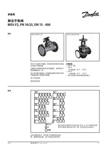
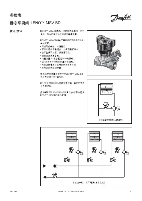
参数表静态平衡阀MSV-F2, PN 16/25, DN 15 - 400描述MSV-F2 为静态平衡阀。
它用在供热和制冷定流量水系统中平衡流量。
这种阀门标配阀位指示和行程限制。
阀杆罩与行程限制集成为一体。
阀门设定值可被锁定。
在测量仪器PFM3000/4000中建有该阀门流量特性数据。
阀门不含石棉。
具有关断功能主要数据:• DN 15- 400• PN 16: - 水流温度: –10 °C … 130 °C • PN 25:- 水流温度: –10 °C … 150 °C• 阀门可安装与供水管或回水管上。
MSV-F2 DN 15-150应用MSV-F2 DN 200-400在定流量系统中,MSV 阀门可保持恒定的压降。
根据预设定值,阀门可设定多种压降。
订货附件型号产品编号Rectus型快速测量接头003Z0108针式测量接头,2 件003Z0104加长型针式测量接头45 mm,2 件003Z0103针式测量接头连接件,2 件003Z0107 PFM4000测量仪器参见相关参数表型号产品编号手轮DN 15- 50003Z0179DN 65- 150003Z0180DN 200003Z0181DN 250- 300003Z0182DN 350- 400003Z0183MSV-F2 阀门 - PN 16公称直径DN 1520253240506580100125150200250300350400k vs (m 3/h ) 3.16.39.015.532.353.893.4122.3200.0304.4400.8685.6952.31380.22046.12584.6公称压力(Bar)16最大压降(Bar)1.5泄漏率 A 级:依照 ISO5208,表 5(无可见渗漏)流体介质水以及水与辅助冷却剂(如乙二醇)的混合物* ,用于闭式供暖和制冷系统流体最高温度(°C) 130连接符合 EN 1092-2 标准的法兰重量(闭式) 2.32.93.85.67.29.41721324356231354497747890阀体材料铸铁 EN-GJL 250 (GG 25)阀座密封EPDM圆锥材料CW602NCuSn5Zn5Pb5铸造不锈钢* 请向供应商确认材料与辅助冷却剂的相容性。
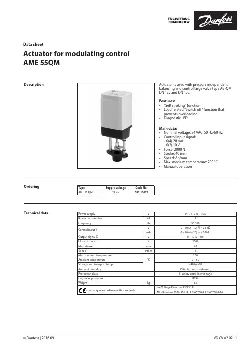
© Danfoss | 2016.09VD.CV.A2.02 | 1Actuator for modulating control AME 55QMData sheetActuator is used with pressure independent balancing and control large valve type AB-QM DN 125 and DN 150.Features:• “Self stroking” function• Load related “Switch off“ function that prevents overloading • Diagnostic LEDMain data:• Nominal voltage: 24 VAC, 50 Hz/60 Hz • Control input signal: - 0(4)-20 mA - 0(2)-10 V • Force: 2000 N • Stroke: 40 mm • Speed: 8 s/mm• Max. medium temperature: 200 °C • Manual operationDescriptionOrderingType Supply voltageCode No.AME 55 QM24 V~082H3078Technical dataPower supply V 24~; +10 to – 15%Power consumption VA 9Frequency Hz 50 / 60Control input Y V 0 – 10 (2 – 10) Ri = 24 kΩmA 0 – 20 (4 – 20) Ri = 500 ΩOutput signal X V 0 – 10 (2 – 10)Close of force N 2000Max. stroke mm 40Speeds/mm 8Max. medium temperature °C200Ambient temperature 0 – 55Storage and transport temp. –40 to +70Ambient humidity 95% r.h., non-condensing Protection class III safety extra-low voltageDegree of protection IP 54Weight kg 3.8- marking in accordance with standardsLow Voltage Directive 73/23/EECEMC-Directive 2006/95/EEC, EN 60730-1, EN 60730-2-14Data sheet Actuator for modulating control AME 55 QM2 | © Danfoss | 2016.09VD.CV.A2.02Installation MechanicalThe actuator should be mounted with the valvestem in either horizontal position or pointingupwards. Use a 4 mm Allen key (not supplied) tofit the actuator to the valve body.Allow for necessary clearance for maintenancepurposes.The valve has position indication ringswhich should be pushed together beforecommissioning; after stroking they indicate theends of the stroke.ElectricalElectrical connections can be accessed byremoving the cover. Two M16 × 1.5 cable entriesare provided. Both entries are provided with arubber grommet for use with flexible cable. Notethat in order to maintain the enclosure IP rating,appropriate cable glands must be used.Wiring The actuator must be dismantled and the elements sorted into various material groups before disposal.Disposal 24 Vac only.Wiring length Recommendedsquare of the wiring0-50 m0.75 mm2> 50 m 1.5 mm2Automatic self stroking featureWhen power is first applied, the actuator willautomatically adjust to the length of the valvestroke. Subsequently, the self stroking featurecan be re-initialised by changing position of SW9.Diagnostic LEDThe red diagnostic LED is located on the pcbunder the cover. It provides indication of threeoperational states:• Actuator Healthy (Permanently ON),• Self Stroking (Flashes once per second),• Error (Flashes 3 times per second - seektechnical assistance).Data sheetActuator for modulating control AME 55 QM© Danfoss | 2016.09 | 3VD.CV.A2.02DIP switch settingThe actuator has a function selection DIP switch under the removable cover. In particular, if SW6 is set to ON, the actuator will perform as 3-point actuator.The switch provides the following functions:• SW1: U/I - Input signal type selector:If set to OFF position, voltage input is selected. If set to ON position, current input is selected.• SW2: 0/2 - Input signal range selector:If set to OFF position, the input signal is in the range from 2 V to 10 V (voltage input)or from 4 mA to 20 mA (current input). If set to ON position, the input signal is in the range from 0 V to 10 V (voltage input) or from 0 mA to 20 mA (current input).• SW3: D/I - Direct or inverse acting selector:If set to OFF position, the actuator is direct acting (stem contracts as voltage increases). If actuator is set to ON position the actuator is inverse acting (stem extracts as voltage increases).• SW4: —/Seq - Normal or sequential modeselector:If set to OFF position, the actuator is working in range 0(2)..10V or 0(4)..20mA. If set to ON position, the actuator is working in sequential range; 0(2)..5 (6)V or (0(4)..10 (12)mA) or (5(6)..10V) or (10(12)..20mA).• SW5: 0..5V/5...10V - Input signal range insequential mode:If set to OFF position, the actuator is working in sequential range 0(2)..5 (6)V or 0(4)..10 (12)mA. If set to ON position, the actuator is working in sequential range; 5(6)..10V or 10(12)..20mA.• SW6: Prop./3-pnt - Modulating or 3-point modeselector:If set to OFF position, the actuator is working normally according to control signal. If set to ON position, the actuator is working as 3-point actuator.For this operation please refer to page 2(wiring 3-point control).When DIP switch SW6 is set to ON than allfunctions from other DIP switch become inactive.• SW7: LOG/LIN - Equal percentage or linear flowthrough valve selector:If set to OFF position, the flow through valve is equal percentage. If set to ON position, the flow through valve is linear according to control signal.• SW8: 100% K VS/Reduced K VS :To be set to OFF position (no sense in combination with AB-QM).• SW9: Reset:Changing this switch position will cause the actuator to go through a self stroking cycle.Complete the mechanical and electricalinstallation and perform the necessary checks and tests:• Isolate control medium. (e.g. self stroking in a steam application without suitable mechanical isolation could cause a hazard).• Apply the power. Note that the actuator will now perform the self stroking function.• Apply the appropriate control signal and check the valve stem direction is correct for the application.• Ensure that the actuator drives the valve over its full stroke, by applying the appropriate control signal. This action will set the valve stroke length.The unit is now fully commissioned.CommissioningCommissioning / testing featureThe actuator can be driven to the fully open or closed positions (depending on valve type) by connecting SN to terminals 1 or 3.VD.CV.A2.024 | © Danfoss | DHS-SRMT/SI | 2016.09Data sheetActuator for modulating control AME 55 QMActuator - valve combinationsThe manual override is applied by rotating the 4 mm Allen key (not supplied) to the required position. Observe the direction of the rotation symbol.• Disconnect power supply• Adjust valve position using an Allen key • Set valve to closed position •Restore power supplyIf manual override has been used then X and Y signal are not correct until the actuator reaches its end position. If this is not accepted reset the actuator, or apply accessory active return signal kit.DimensionsManual override。
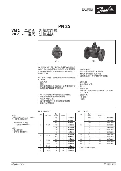
© Danfoss | 2016.02ED.LH.M2.41 | 1压力平衡型调节阀体(PN 25)VM 2 – 二通阀,外螺纹连接VB 2 – 二通阀,法兰连接技术手册VM 2 VB 2VM 2 型和 VB 2 型二通阀与丹佛斯电动驱动器 AMV(E) 10、AMV(E) 20 和 AMV(E) 30;或者带弹簧复位功能的丹佛斯电动驱动器 AMV(E) 13、AMV(E) 23 和 AMV(E) 33。
VM 2 型和 VB 2 型二通阀能够在要求苛刻的系统使用,例如:- 区域供热- 供热- 采用换热器的热水供应系统,或需要确保性能长期稳定的罐式蓄热换热系统。
特点:• 专门针对苛刻应用的分段线型控制特性• 小型驱动器能够达到高关闭压差• 可提供多种 k VS 值 • 采用推拉式连接,便于驱动器机械连接• 最低控制范围50:1优势:• 调节快速稳定• 生活热水温度稳定,更加舒适• 稳定的控制性能,更加节能 • 温度波动更小,零部件使用寿命更长主要数据:• DN 15-50• k VS 0,25-40 m 3/h • PN 25• 介质温度: - 循环水 / 浓度不超过 30 % 的乙二醇溶液: 2 … 150 °C • 连接方式: - 外螺纹 - 法兰订货例如:二通阀门 VM 2; DN 15; k VS 1,6; PN 25; T max 150 °C; 外螺纹连接- 1× VM 2 DN 15 阀门 订货号:065B2014选配:- 1× 连接尾件 订货号:003H6908VM 2 (外螺纹)DN外螺纹k VS 行程订货号ISO 228/1(m 3/h)(mm)15G ¾ A0,255065B20100,45065B20110,635065B20121,05065B20131,65065B20142,55065B20154,05065B202620G 1 A 4,05065B20166,37065B202725G 1¼ A 6,35065B20178,05065B202832G 1½ A 107065B2018G 1¾ A 107065B202940G 2 A 1610065B201950G 2½ A2510065B2020VB 2 (法兰)DNk VS 1)行程订货号(m 3/h)(mm)150,255065B20500,45065B20510,635065B20521,05065B20531,65065B20542,55065B20554,05065B2056206,35065B205725107065B2058321610065B2059402510065B2060504010065B20611)k VS 符合 VDI/VDE 2173 标准说明技术手册压力平衡型阀体 VM 2 和 VB 22 | © Danfoss | 2016.02ED.LH.M2.41VM 2 备件阀芯组件阀门口径订货号DN 15/1,0065B2033DN 15/1,6065B2034DN 15/2,5065B2035DN 15/4,0065B2036DN 20/4,0065B2036DN 20/6,3065B2037DN 25/6,3065B2037DN 25/8,0065B2041DN 32/10065B2038DN 40/16065B2039DN 50/25065B2040VB 2 备件填料盒阀门口径订货号DN 15-50065B2070VM 2 配件(两套连接尾件)DN 外螺纹ISO 228/1焊接尾管1)外螺纹连接尾管1)订货号订货号15G ¾ A 003H6908003H690220G 1 A 003H6909003H690325G 1¼ A 003H6910003H690432G 1¾ A 003H69112)003H69052)32G 1½ A 003H69143)003H69063)40G 2 A 065B2006065B200450G 2½ A065B2007065B20051)焊接尾件(钢),外螺纹尾件G转R (黄铜)2) 适用阀门型号 065B2029 (G 1¾ A)3)适用阀门型号 065B2018 (G 1½ A)订购(续)技术参数公称直径DN 152025324050k VS 值 VM 2m 3/h 0,250,400,631,01,62,54,04,06,36,38,0101625VB 26,310162540行程 VM 2mm55755710VB 25710控制精度> 50:1控制特性折线型控制特性气蚀系数 z≥ 0,5泄漏率(按照 IEC 534 标准)最高为Kvs 值的 0,05%公称压力PN 25介质循环水 / 浓度不超过 30 % 的乙二醇溶液介质 pH 最小7,最大10介质温度 °C 2 (150)连接方式VM 2外螺纹连接符合 EN 228-1 标准VB 2PN 25 法兰连接符合 EN 1092-2 标准材料VM2VB2阀体红铜(Rg 5)球墨铸铁EN-GJS-400-18-LT (GGG 40.3)阀盖-阀锥、阀座和阀杆不锈钢填料盒密封EPDM O 型圈VM 2 关闭压差 Δp型号DN k VSAMV(E) 10/13AMV(E) 20/23, 30/33(mm)(米3/小时)(bar )(bar )VM 2150,25/-4,0.1616204,02525206,3-25256,31625258,016253210-254016-165025-16VB 2 关闭压差 Δp类型DN k VSAMV(E) 10/13AMV(E) 20/23, 30/33(mm)(米3/小时)(bar)(bar)VB 215/-20.0,25/-6,3.161625/-50.10/-40.-16技术手册压力平衡型阀体 VM 2 和 VB 2© Danfoss | 2016.02 | 3ED.LH.M2.41压力-温度线废弃处理阀门废弃之前需先拆卸解体,并将其元件分类处理。